

Page 1
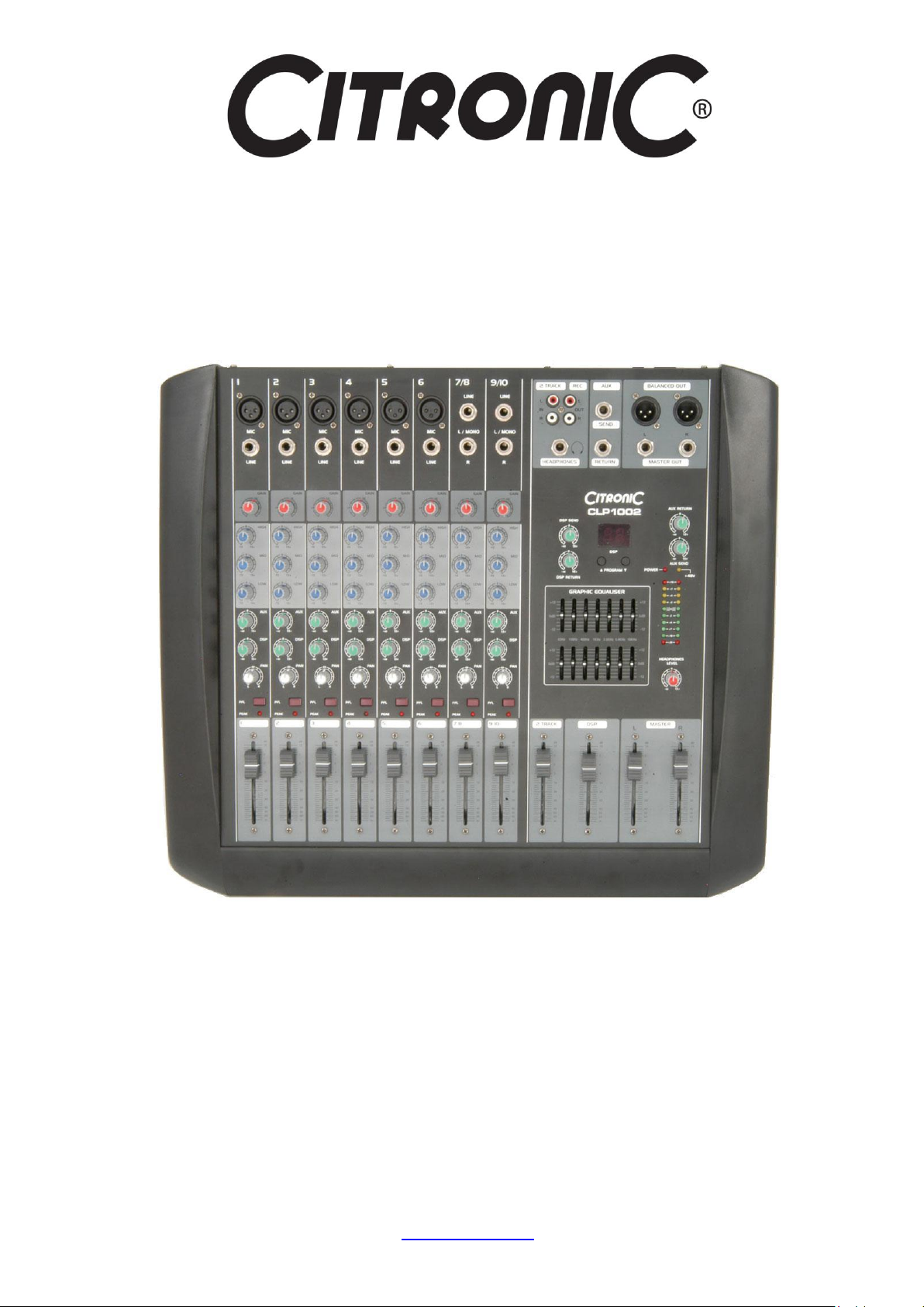
CL1002 mixer 170.860
CLP1002 powered mixer 170.870
User Manual
Features:
Internal 16 program DSP effects
6 Mic/Line + 2 Stereo Line channels
3-band EQ per channel
+48V phantom power
19” rack-mounting kit included
2 x 7-band master graphic EQ
AUX Send and Return
CLP models with internal stereo power amp
www.citronic.com
Page 2
Introduction:
SPECIFICATIONS
CL1002
CLP1002
Power supply
220-250Vac, 50Hz
Inputs : Mic/Line
6 x balanced XLR/6.3mm jack
Phantom power
+48V to XLR inputs (switchable)
Inputs : Line
2 x stereo L+R 6.3mm jack, 2-track in (L+R RCA)
Input sensitivity
Mic -60dB, Line -45dB
THD
≤0.05%
S/N ratio
≥95dB
Frequency response
20Hz - 20kHz
Effect presets
16 x DSP reverb/delay algorithms
Output : Mix
2 x balanced XLR/6.3mm jack + Rec. out (L+R RCA)
Auxillary output
Aux send and return (6.3mm jack)
EQ controls
Channel High, Mid, Low + master 7-band graphic
Power rms : 4 Ohms
N/A
2 x 350W
Power rms : 8 Ohms
N/A
2 x 250W
Speaker outputs
N/A
2 x SPK connectors
Dimensions
510 x 100 x 455mm
510 x 150 x 480mm
Weight
6.37kg
12.38kg
Thank you for choosing this Citronic CL/CLP series mixer. This product has been designed to offer reliable, high quality mixing
for stage and/or studio applications with unfailing consistency. In order to gain the best results from this equipment and avoid
damage through misuse, please read and follow these instructions and retain for future reference.
Warning:
To prevent the risk of fire or electric shock, do not expose any of the components to rain or moisture.
If liquids are spilled on the surface, stop using immediately, allow unit to dry out and have checked by qualified personnel before
further use.
Avoid impact, extreme pressure or heavy vibration to the unit.
There are no user serviceable parts inside the mixer – refer all servicing to qualified service personnel.
Safety
Check that the supplied mains lead is in good condition and the mains supply voltage is correct.
Ensure signal and speaker leads are of good condition – ensure that there are no shorted connections
For CLP models, ensure that the minimum combined speaker load for each channel is 4Ω
Do not allow any foreign particles to enter the console through connectors, control apertures or vents
Do not cover or obstruct cooling vents
Placement
Keep out of direct sunlight and away from heat sources.
Keep away from damp or dusty environments.
When rack-mounting, use rack ears supplied, securing firmly.
Ensure adequate access to controls and connections
Ensure adequate air-flow for cooling
Cleaning
Use a soft cloth with a neutral detergent to clean the casing as required
Use a soft brush to clear debris from the control surface and vents
Do not use strong solvents for cleaning the unit.
Page 3

Channel Strip Master Section
1. XLR microphone or low impedance line input
2. Stereo line inputs 6.3mm jack unbalanced
3. Mono line input 6.3mm jack unbalanced
4. Channel GAIN control
5. 3-band EQ (HIGH/MID/LOW) controls
6. Channel AUX SEND level
7. DSP rotary adjusts level sent to onboard DSP effects
8. PAN control for stereo position (Left – Centre – Right)
9. PFL (Pre-Fade Listen) for monitoring and gain setting
10. PEAK LED illuminates when channel is clipping
11. Channel fader
12. REC output L+R RCA connectors
13. 2-TRACK input L+R RCA connectors
14. HEADPHONES output 6.3mm stereo jack
15. DSP PROGRAM up/down buttons & LED display
16. DSP SEND controls overall level sent to internal DSP
17. DSP PARAMETER adjusts character of selected effect
18. Dual 7-band MASTER graphic EQ
19. DSP level fader
20. 2-TRACK fader
21. Master output L+R balanced XLR
22. Master output L+R balanced 6.3mm jack
23. AUX SEND + RETURN 6.3mm mono jacks
24. AUX RETURN level control
25. AUX SEND level control
26. POWER and +48V LED indicators
27. VU meter LEDs
28. HEADPHONES LEVEL control
29. L+R MASTER faders
Page 4

Rear Panel
30. IEC mains inlet & fuse
31. POWER switch
32. PHANTOM power switch
33. Speaker outputs (CLP1002 only)
34. Cooling vents
Connection
Before connecting to amplifier, speakers or other equipment, turn down all volume controls to avoid loud noises which may
cause damage to other equipment. Always switch amplifier power on last in line with volume levels down.
Using good quality 6.3mm jack or XLR leads (balanced or unbalanced), connect L + R MASTER outputs from the mixer to the
amplifier, recorder or whichever equipment is to receive the main mix output.
If phantom power is to be used, switch in the PHANTOM on the rear panel
Connect microphones, DI boxes and other balanced low impedance audio inputs to the mono channels using a quality XLR lead.
Connect high impedance and line level signals to the mono inputs using a 6.3mm jack lead.
For stereo channels, connect left and right line level signals via 6.3mm jack – use left only for mono signals.
An additional 2 TRACK input is provided for playback devices on stereo RCA connectors and recording equipment can be
connected via the “REC” outputs using a twin RCA lead
The 6.3mm jack AUX SEND can be connected to monitoring or external processing equipment if required and the output of
external processing equipment can be brought back into the mix by connecting it to AUX RETURN.
For monitoring, headphones can be connected to the 6.3mm stereo HEADPHONES jack.
For CLP models, connect speakers via the LEFT and RIGHT Speaker Outputs on the rear panel, ensuring that the combined
load on each channel is no lower than 4Ω and the speakers are capable of the amplifier’s rated output.
With all faders down, connect the supplied mains lead to the mains supply and IEC inlet (ensure correct supply voltage). Switch
POWER on and the power LED will illuminate (if phantom power is selected, this LED should light also)
Page 5

Checking
Program
Effect Type
Parameter
Program
Effect Type
Parameter
1
Chorus
Depth
9
Reverb: Bright Room
Reverb time
2
Reverb: Dark Room
Reverb time
10
Delay + Reverb 1
Delay time
3
Delay
Delay time
11
Reverb: Cavern
Reverb time
4
Flanger
Rate
12
Reverb: Concert
Reverb time
5
Detune
Rate
13
Reverb: Dark Hall
Reverb time
6
Phaser
Rate
14
Reverb: Bright Hall
Reverb time
7
Rotary
Rate
15
Reverb: Cathedral
Reverb time
8
Reverb: Tunnel
Rate
16
Delay + Reverb 2
Delay time
Set all HIGH, MID, LOW and PAN controls to the mid position (12o’clock) and AUX/DSP controls fully left (-∞)
Test each channel’s gain level by pressing in the PFL (Pre-Fade Listen) switch. If any PFL switches are on, the VU meters will
display the output of the PFL channel(s) instead of the overall output.
Make the loudest expected sound through that channel and increase the GAIN control until the signal reaches the 0dB mark.
Dynamic attacks, like the strike of a drum or pluck of a string, may be allowed to go into the amber coloured LEDs (up to +7dB)
but the red LEDs (+10dB) represent clipping, which should be avoided.
Once the GAIN is set, switch off the PFL for that channel and repeat the process for all other input channels.
Test the main mix output by gradually increasing the MASTER faders and selected channel faders whilst making sound through
the channel(s) – the L + R output LED ladders should begin to show the output as it varies up and down. Output will be heard
through any connected headphones or speakers.
Operation
Each channel has a 3-band EQ (LOW/MID/HIGH), which can be used to balance the mix of frequencies and emphasise certain
aural characteristics in the signal. Adjust these as required, noting that and overall increase may require an equivalent reduction
of the GAIN control to compensate (otherwise clipping may occur from EQ boost).
An individual PEAK LED on each channel helps to show if any channel input is clipping.
Use the PAN control to position the channel input either to the left or right side of the stereo field. This can be useful to help
separate and define sounds within a mix but be aware that extreme settings can be counter-productive by removing the channel
from certain listening positions.
Use the AUX control to feed the correct amount of the channel signal to the AUX SEND. The combined AUX SEND level from all
channels is governed by the AUX SEND rotary control. Likewise, the AUX RETURN rotary control determines the level fed back
into the mixer via the AUX RETURN jack. Adjust AUX SEND so that its output does not overload connected equipment and
match the level brought back with the AUX RETURN control.
Each channel has a DSP control which feeds a portion of the signal to the internal DSP (Digital Signal Processor)
The internal DSP section can provide one of 16 internal effect types, as listed below…
Each effect has a particular adjustable setting which can be altered, changing the nature of the chosen effect program. These
are listed in the table above and the best setting can be found for each by experimentation with the DSP PARAMETER control.
Overall DSP effect level fed to the mix is controlled via the DSP fader.
There is also a 2-TRACK fader to adjust the level of the signal fed in via the 2-TRACK RCA inputs.
Channel faders should be used to adjust the individual levels in the mix and the MAIN fader is for overall level.
Turn down MASTER levels when changing any connections or powering down the mixer to avoid speaker damage
Page 6

Troubleshooting
No power LED on control panel
Ensure power lead is in good condition and connected properly
Ensure mains outlet voltage is as stated on adapter
Check internal fuse – if blowing fuses, refer to service personnel
Power LED is on but no other LEDs and no output
Check input signals and condition of connection leads
Check GAIN is not too low on channel input
Check channel fader, GAIN and EQ controls are not turned fully down
Check MASTER faders are not fully down
For condenser mics, turn down MASTER faders and check phantom is on
Check that PFL buttons are all switched out
Check that all Graphic EQ sliders are not fully down
Power light and VU LEDs lighting but no output
Check output connections to amplifier, recorder or speakers
Check amplifier or recorder levels are not turned fully down
Check that PFL buttons are all switched out
No output from stereo channels
Check that mono input is connected to L/MONO jack
VU LEDs do not show MASTER output level
Check that PFL buttons are all switched out
Output is very loud or distorted
Check level of input signal is not too high
Reduce channel GAIN and EQ settings
Reduce channel and MAIN faders levels
Ensure Hi-Z line level input(s) not connected via XLR
Check output levels of equipment connected via channel inserts
Check AUX and DSP level controls and reduce if necessary
Check input gain level on recorder or recording software
Output is working but at very low level
Check input audio source level is not too low
Ensure low impedance line or mic signal is not connected via jack
Increase channel GAIN control and EQ settings if turned down
Increase channel and MAIN faders levels
Check input gain level on recorder or recording software
Feedback (loud squealing or howling from mics)
Face microphone away from speakers and monitors
Reduce channel GAIN level and EQ level(s)
Reduce AUX and/or EFFECT levels
Reduce channel and/or MAIN fader levels
Note: for further troubleshooting, refer equipment to qualified service personnel for testing
© Citronic 2011
 Loading...