

Page 1
Technology Corporation
®
Expert Solutions for the LAN Environment
SwitchView
Installer/User Guide
™
®
Page 2

©2000 Avocent Corporation. All rights reserved.
Avocent and the Avocent logo are trademarks or registered trademarks of Avocent Corporation. SwitchView is a registered
trademark of Cybex Computer Products Corporation. All other marks are the property of their respective owners.
Page 3

Product Overview
Feature Overview
The SwitchView allows you to control multiple PCs,
easily and affordably, with just one keyboard, monitor
and mouse. There is no software to install or boards
to configure, so installation is simple. SwitchView works
with IBM PC/AT and PS/2 systems with support for
VGA and SVGA video. PS/2 keyboard and PS/2 mouse
peripherals are supported through the rear of the unit.
When you turn on your PCs, the SwitchView will boot
up each one without interruption by sending out the
proper signal to eliminate keyboard errors. PCs may be
powered-up one-at-a-time or all at once. The first available channel is automatically selected upon power-up.
You can switch computer channels two ways: via the
Select button on the SwitchView front panel, or through a
short keyboard sequence if the SwitchView is out of reach.
The SwitchView supports the following additional features:
• PS/2 mouse translation - your PS/2 mouse will
• Extensive Mouse Support - The SwitchView
• Standard cables - use either Avocent-supplied or
• Built-in scanning feature - scan through all of
work with any attached PC, regardless of whether
the computer is serial or PS/2 mouse compatible!
offers full support for the Logitech MouseMan
Wheel, Logitech Trackman Marble Wheel, Logitech
Trackman Marble FX, Microsoft Explorer mouse and
the Microsoft IntelliMouse family.
standard straight-through cables to attach computers to the SwitchView unit.
your attached PCs automatically. Scan every PC for
2 to 60 seconds each.
1
Page 4

SwitchView User Manual
• Hot-pluggable - new PCs can be added or
removed without powering down the SwitchView
unit or other attached PCs.
• Status LEDs - two LEDs per computer give you
constant readings on the status of your SwitchView unit.
Specifications
Mechanical
2-Port 4-Port
Height:1.9" (4.83 cm) Height:1.9" (4.83 cm)
Width: 8.1" (20.57 cm) Width: 8.1" (20.57 cm)
Depth: 5.0" (12.7 cm) Depth: 5.0" (12.7 cm)
Environmental/Power
Operating Temperature: 41° (5°C) to 104° (40°C)
Storage Temperature: -4° (-20°C) to 122° (50°C)
Optional Power Supply: 6VDC @ 700 mA
Supported Hardware
Computer: IBM PC/AT, PS/2 and 100% compatibles
Video Modes: VGA and SVGA
Maximum Resolution: 1600 x 1200 @ 75 Hz
Peripherals: PS/2 keyboard, PS/2 mouse
Regulatory Compliance Standards
UL 1950, CSA C22.2 No. 950, EN60950
FCC part 15B, EN55022, EN50082, CISPR22, ICES-003
Under certain circumstances it may be necessary to
power the SwitchView with an external power supply. If
this is necessary, the power supply should be a Listed
Direct Plug-In Transformer unit marked “Class 2” or
“L.P.S.” and rated at 6 VDC, 700 mA.
2
Page 5
Installation
Basic Install
Before you install
In order to connect your PCs to the SwitchView, you will
need the appropriate connecting cables. We recommend
these Avocent cable kits:
For PS/2 PSs: CPS2-6A For AT/serial PCs: CSER-6A
The SwitchView also accepts standard straight-through
cables for these connections.
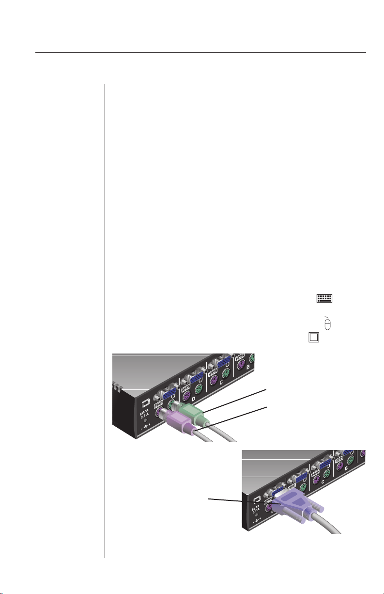
Connecting your peripherals
1. Your VGA monitor, keyboard and mouse connect to
the SwitchView unit instead of your computer. Plug
your PS/2 keyboard cable into the purple port
on the back of your unit in the User Console section.
Plug your PS/2 mouse cable into the green port
and your VGA video cable into the blue port.
VGA VIDEO CABLE
PS/2 MOUSE CABLE
PS/2 KEYBOARD CABLE
3
Page 6

SwitchView User Manual
Connecting your Computers
2. Power down all computers that will be part of your
SwitchView system.
3. Locate the appropriate cable kit to attach your first
computer to the SwitchView. Now, plug the keyboard cable from the kit into the purple connector of any available port on your SwitchView.
Ports are labeled A-B on the 2-Port and A-D on
the 4-Port.
Next, plug your mouse cable into the green con-
nector of the same port.
Plug the video cable into the blue monitor connector.
Plug the remaining cable ends into the matching
ports on your computer. For serial computers,
use only Avocent provided adaptors. Tighten all
thumbscrews.
4. Repeat step 3 for each additional computer to be
attached and then power-up all attached computers.
4
Page 7

Basic Operations
PCs may be powered-up one-at-a-time or all at once.
The green LEDs over each channel will light, indicating
that the attached computer is powered on. After
power-up, a lit amber LED indicates the selected computer. Other PCs may now be selected for operation.
Selecting a PC
There are two ways to select a PC. One way is via
the Select push-button. This selects the next computer
in sequence. Holding the push-button down will enable
scanning of all available channels until the button is
released. The second way is by entering a short sequence
of keystrokes on the keyboard. This is called keyboard, or
hot-key, switching.
Press the Control key twice within one second to place
your SwitchView in Command Mode. Your keyboard
LEDs will flash to verify that you are operating in Command Mode. Now, whatever you type will be interpreted as
SwitchView system commands until Enter is pressed to
accept the command or Escape is pressed to cancel.
In Command Mode, type the letter for the PC you wish
to select. Press Enter to accept the new address (Addr).
See below.
Key Sequence Action
<CTRL><CTRL>Addr<Enter> Selects an active channel via keyboard.
EXAMPLE
Key Sequence Action
1. <CTRL><CTRL>B<Enter> Selects Channel B.
2. <CTRL><CTRL>C<Enter> Selects Channel C.
5
Page 8

SwitchView User Manual
Scanning PCs
The scanning feature allows you to automatically monitor, or scan, each PC in your SwitchView system. If you
use the keyboard during scanning, the scan will pause
until you finish, then resume with the next PC. The
length of time each PC’s video remains on the screen, or
dwell time, can be changed at any time. Scanning will
be halted if the Halt command is entered or if another
PC is selected.
The following key sequences control scanning:
Key Sequence Action
<CTRL><CTRL>Dnn<Enter> Congures the dwell time. Substitute nn
<CTRL><CTRL>SG<Enter> Enables the scan Go command.
<CTRL><CTRL>SH<Enter> Enables the scan Halt command.
with a value from 2 to 60 seconds. The
default value is 5 seconds.
If you would like mouse and keyboard activity to suspend scanning, see the commands below.
Key Sequence Action
<CTRL><CTRL>M+<Enter> Mouse will suspend scanning.
<CTRL><CTRL>M-<Enter> Mouse will not suspend scanning. (default)
EXAMPLE
Key Sequence Action
1. <CTRL><CTRL>D10<Enter> Each PC’s video will remain on the
2. <CTRL><CTRL>SG<Enter> Scanning begins with the current
3. <CTRL><CTRL>SH<Enter> Scanning is halted until the Go
6
screen for 10 seconds before the
next channel is displayed.
computer, then continues to the
next PC in sequence.
command is issued again.
Page 9

Troubleshooting
Unit
Green channel LED not lit
Verify that the computer is powered on. Check the
cabling between your computer and the SwitchView.
Verify that a keyboard works when plugged directly into
your PC. If the connection is to a laptop mouse, the
green LED will not light but the port can still be selected.
Unable to switch channels
Verify that all attached PCs are powered and correctly
connected to the unit.
Unable to hot-key
After a power loss, the unit will default to the <CTRL>
<CTRL> key sequence. Try using <CTRL> <CTRL> to hotkey switch.
Video
No video
Verify that the video cable between the computer and
the SwitchView is connected to the selected port. Verify
that the monitor cable is correctly connected to the
SwitchView.
Power down the computer. Connect the monitor directly
to the computer and power up again. If the monitor does
not operate correctly direct to the computer, try another
monitor.
Verify that the cables from the computer to the SwitchView are connected properly.
7
Page 10

SwitchView User Manual
Mouse
Mouse jumps or “hugs” screen
If the mouse has been hot-plugged while running in
Windows, you may need to close and restart Windows.
If the mouse still does not function, try the mouse resynchronization command: <CTRL><CTRL>ZM<Enter>.
Mouse is inoperable on one or more channels
Try the mouse reset command: <CTRL><CTRL>MR<Enter>
or <CTRL><CTRL>MW<Enter> depending on the type of
mouse you have. Check the table below for the appropriate
keyboard sequence. If your mouse type is not listed, use the
MR keyboard sequence.
Verify that the mouse is plugged into the mouse port in
the User Console area on the rear panel of the unit.
Verify that the computer works properly with a mouse
connected directly to it. If not, try another mouse.
If you are using a serial mouse, verify that you are using
an Avocent Serial Mouse adaptor.
Microsoft
Peripheral Mouse
Intellipoint
Driver
Logitech MouseMan Wheel MW MR
Logitech Trackman Marble Wheel MW MR
Logitech Wheel Mouse MW MR
Logitech Trackman Marble FX MR MR
Logitech Marble Mouse MR MR
Three Button MR MR
Microsoft IntelliMouse MW MW
Microsoft Explorer MW MW
8
Logitech
MouseWare
Driver
Page 11

Keyboard
Keyboard is inoperable on one or more channels
Verify that the cables from the PC to the SwitchView are
connected properly.
Verify that the keyboard is plugged into the keyboard
port in the User Console area on the rear panel of the
unit.
Verify that the keyboard works properly connected
directly to the computer. If not, try a different keyboard.
If the keyboard still does not function, cycle power on all
attached computers and try again.
Keyboard is inoperable after switching channels or
characters on screen do not match keyboard input
Try changing the keyboard scan set by using the keyboard command sequence: <CTRL><CTRL>Kn<Enter>,
where n is a scan set number 1-3.
If you require any further assistance, please contact
Avocent Customer Support.
9
Page 12

SwitchView User Manual
Appendix
The following is a summary of all operational commands.
Key Sequence Action
<CTRL><CTRL>Addr<Enter> Selects an active channel via keyboard.
<CTRL><CTRL>Dnn<Enter> Congures the dwell time. Substitute nn with
<CTRL><CTRL>SG<Enter> Enables the scan Go command.
<CTRL><CTRL>SH<Enter> Enables the scan Halt command.
<CTRL><CTRL>M+<Enter> Mouse will suspend scanning.
<CTRL><CTRL>M-<Enter> Mouse will not suspend scanning. (default)
<CTRL><CTRL>MR<Enter> If you hot-plug the SwitchView to a PC con-
a value from 2 to 60 seconds.
nection you may experience a loss of mouse
signal. Use this command to restore the signal
if you’re using a PC with a standard PS/2
mouse driver. (See page 8)
<CTRL><CTRL>MW<Enter> Use this command to restore the mouse signal
<CTRL><CTRL>Kn<Enter> Sets keyboard scan set; n is a number 1 - 3.
<CTRL><CTRL>AV<Enter> Displays the current rmware version of the
<CTRL><CTRL>H1<Enter> Default Command Mode Activation
<CTRL><CTRL>H2<Enter> Changes the Command mode activation
<CTRL><CTRL>H3<Enter> Changes the Command mode activation
<CTRL><CTRL>H4<Enter> Changes the Command mode activation
<CTRL><CTRL>ZM<Enter> Used to resynchronize the mouse after a hot-
NOTE: Using this command while the mouse
if you’re using a PC with a Microsoft IntelliMouse driver. (See page 8)
SwitchView processors. You must be at a DOS
prompt or in a text editor/word processor to
view this information.
sequence to <ALT> <ALT>
sequence to <Shift> <Shift>
sequence to <NUMLOCK> <->
plug. Repeat, if necessary, until synchroniza-
tion is re-established.
is operating correctly will cause the mouse
to lose sync.
10
Page 13

U.S.A.
Federal Communications Commission (FCC)
Warning: Changes or modifications to this unit not expressly approved
by the party responsible for compliance could void the user's authority
to operate the equipment.
Note: This equipment has been tested and found to comply with
the limits for a Class B digital device, pursuant to Part 15 of the
FCC Rules. These limits are designed to provide reasonable protection
against harmful interference in a residential installation. This equipment generates, uses and can radiate radio frequency energy and, if
not installed and used in accordance with the instructions, may cause
harmful interference to radio communications. However, there is no
guarantee that interference will not occur in a particular installation. If
this equipment does cause harmful interference to radio or television
reception, which can be determined by turning the equipment off and
on, the user is encouraged to try to correct the interference by one or
more of the following measures:
- Reorient or relocate the receiving antenna.
- Increase the separation between the equipment and the receiver.
- Connect the equipment into an outlet on a circuit
different from that to which the receiver is connected.
- Consult the dealer or an experienced radio/TV technician for help.
Canada
Industry Canada (IC)
This digital apparatus does not exceed the Class B limits for radio
noise emissions from digital apparatus set out in the Radio Interference Regulations of the Canadian Department of Communications.
Le présent appareil numérique n’émet pas de bruits radioélectriques
dépassant les limites applicables aux appareils numériques de la classe
B prescrites dans le Règlement sur le brouillage radioélectrique édicté
par le Ministère des Communications du Canada.
Japan
Voluntary Control Council for Interference (VCCI)
Standards
Page 14

Page 15

Warranty
Avocent Corporation warrants to the original retail purchaser that this product is and will be free from
defects in materials and workmanship for a period of 12 months from the date of purchase.
Additionally, all Avocent products carry an unconditional thirty-day satisfaction guarantee. If, for any
reason, you are dissatised with the performance of this product, you may return it to the point of purchase
for a refund of the purchase price (excluding shipping charges). This guarantee does not apply to special
order products, and may not be available through all resellers. During the warranty period, purchaser must
promptly call Avocent for a RETURN MATERIALS AUTHORIZATION (RMA) number. Make sure that the
RMA number appears on the packing slip, proof of purchase, AND ON THE OUTSIDE OF EACH SHIPPING
CARTON. Unauthorized returns or collect shipments will be refused.
Ship prepaid to: Avocent Corporation
4991 Corporate Drive
Huntsville, AL 35805 U.S.A.
Telephone: (256) 430-4000
The above limited warranty is voided by occurrence of any of the following events, upon which the product
is provided as is, with all faults, and with all disclaimers of warranty identied below:
1. If non-Avocent approved cabling is attached to the SwitchView. Poorly constructed and miswired
cabling can diminish video quality and damage equipment. Avocent manufactured cabling is built to
high quality standards utilizing overall braided shield to comply with FCC emission standards, and
each cable is individually tested under load.
2. If defect or malfunction was caused by abuse, mishandling, unauthorized repair, or use other
than intended.
3. If unauthorized modications were made to product.
4. If unreported damages occurred in any shipment of the product.
5. If damages were due to or caused by equipment or software not provided by Avocent.
6. If the SwitchView is used with non-grounded or incorrectly polarized AC power.
7. If the product is used in contradiction to any instruction provided by any User Guide or Instruction
Sheet provided to you or with the product.
EXCEPT AS SPECIFICALLY PROVIDED ABOVE AND TO THE MAXIMUM EXTENT ALLOWED BY LAW,
AVOCENT CORPORATION DISCL AIMS ALL WARRANTIES AND CONDITIONS WHETHER EXPRESS,
IMPLIED, OR STATUTORY AS TO ANY MATTER WHATSOEVER INCLUDING, WITHOUT LIMITATION,
TITLE, NON-INFINGEMENT, CONDITION, MERCHANTABILITY OR FITNESS FOR ANY PARTICULAR OR
INTENDED PURPOSE.
EXCEPT AS EXPRESSLY PROVIDED ABOVE AND TO THE MAXIMUM EXTENT ALLOWED BY LAW, AVOCENT
CORPORATION SHALL NOT BE LIABLE FOR ANY SPECIAL, INDIRECT OR CONSEQUENTIAL DAMAGES
(INCLUDING WITHOUT LIMITATION, LOSS OF PROFIT, LOSS OF BUSINESS, LOSS OF INFORMATION,
FINANCIAL LOSS, PERSONAL INJURY, LOSS OF PRIVACY OR NEGLIGENCE) WHICH MAY BE CAUSED BY OR
RELATED TO, DIRECTLY OR INDIRECTLY, THE USE OF A PRODUCT OR SERVICE, THE INABILITY TO USE A
PRODUCT OR SERVICE, INADEQUACY OF A PRODUCT OR SERVICE FOR ANY PURPOSE OR USE THEREOF OR
BY ANY DEFECT OR DEFICIENCY THEREIN EVEN IF AVOCENT CORPORATION OR AN AUTHORIZED AVOCENT
DEALER HAS BEEN ADVISED OF THE POSSIBILITY OF SUCH DAMAGES OR LOSSES.
©2000 Avocent Corporation. All rights reserved.
Page 16

Avocent Corporation
590-115-001 REV. B
4991 Corporate Drive
Huntsville, Alabama 35805-6201
USA
Tel: +1 800 932 9239
Fax: +1 256 430 4031
E-mail: techsupport@avocent.com
Avocent International Ltd.
Avocent House
Shannon Free Zone
Shannon, Co. Clare
Ireland
Tel: +353 61 471 877
Fax: +353 61 471 871
E-mail: techsupp_eur@avocent. ie
Avocent Germany
Dachauerstasse 44a
80335 Munchen
Germany
Tel: +49 89 599 0830
Fax: +49 89 599 08350
E-mail: techsupp_eur@avocent.ie
Avocent Canada
20 Mural Street, Unit #5
Richmond Hill
Ontario, L4B 1K3
Canada
Tel: +1 877 992 9239
Fax: +1 877 524 2985
E-mail: mail@avocentcanada.com
®
T
echnology Corporation
Expert Solutions for the LAN Environment
™
Avocent Asia Pacic
100 Tras Street, #15-01
Amara Corporate Tower
Singapore 079027
Tel: +65 227-3773
Fax: +65 223-9155
E-mail: info.asiapac@avocent.com
Rackit® Technology Corporation
274 Madison Avenue, New York, NY 10016
Tel: (212) 679-0050 • Fax: (212) 679-0040
1.800.636.3434
www.RackitTechnology.com
 Loading...