

Page 1

DSVIEW®3
Installer/User Guide
Page 2

Page 3

DSView® 3
Management Software
Version 3.7
Installer/User Guide
Avocent, the Avocent logo, The Power of Being There, DSView, DSR,
MergePoint, AlterPath, AutoView, OutLook, OSCAR, AVWorks,
LANDesk, Dambrackas Video Compression and Cyclades are registered
trademarks of Avocent Corporation or its affiliates. All other marks are
the property of their respective owners.
© 2008 Avocent Corporation. 590-395-501M
Page 4

Page 5

TABLE OF CONTENTS
Table of Contents
List of Figures ............................................................................................................... xiii
List of Tables..................................................................................................................xv
Chapter 1: Product Overview.......................................................................................... 1
Features and Benefits.................................................................................................................1
System Components....................................................................................................................2
Third party products............................................................................................................3
Partner products..................................................................................................................3
Supported Units................................................................... .......................................................4
Target devices......................................................................................................................7
Power devices....................................................................... ...............................................7
System Configuration .................................................................................................................7
Chapter 2: Installation ..................................................................................................... 9
About Installation .......................................................................................................................9
Installing the DSView 3 Software.............................................................................................10
Upgrading the DSView 3 Software...........................................................................................13
Recommended upgrade process........................................................................................14
Configuring the DSView 3 Software.........................................................................................14
Running the DSView 3 Software . ..............................................................................................16
Uninstalling the DSView 3 Software ........................................................................................18
Closing a DSView 3 Software Session......................................................................................19
Java Installation .......................................................................................................................19
Avocent Viewer Plug-in Installation.........................................................................................20
Installing the DSR Remote Operations Software......................................................................21
iii
Chapter 3: DSView 3 Explorer Windows...................................................................... 23
Accessing Target Devices.........................................................................................................24
Using the Side Navigation Bar.................................................................................................24
Using Windows.........................................................................................................................26
Sorting information in a window.......................................................................................26
Filtering information in a window ....................................................................................26
Saving information in a window........................................................................................27
Using the Customize link in windows........................................................................... .....28
Page 6

iv DSView 3 Software Installer/User Guide
Displaying pages ...............................................................................................................29
Bookmarking a window.....................................................................................................30
Printing a window .............................................................................................................30
Refreshing a window ........................................... ..............................................................30
Using keyboard commands.......................................................................................................31
Chapter 4: Basic Operations......................................................................................... 33
DSView 3 Help.............................................. .................................. ..........................................33
Configuring the DSView 3 help location...........................................................................33
Installing DSView 3 help on a local server....................................................................... 34
Global System Properties.......................... .................................................................... ...........34
Legal Notice..............................................................................................................................35
PCI Compliance Configuration................................................................................................35
Profiles...................................................................................................................................... 36
Changing user options.......................................................................................................36
Changing the color scheme...............................................................................................37
Changing your password...................................................................................................37
Choosing the serial session application............................................................................38
Specifying a user certificate ................................................................................... ...........38
Specifying an SSH key........................................................................ ...............................39
Enabling user credential caching......................................................................................40
Built-in User Groups ................................................................................................................40
Preemption Levels ....................................................................................................................41
Internet Explorer Considerations.............................................................................................42
Certificates................................................................................................................................46
Integrated Windows Authentication .........................................................................................49
Firewalls...................................................................................................................................50
VPNs.........................................................................................................................................51
NAT Devices .............................................................................................................................53
Licenses.....................................................................................................................................54
Adding a new license key...................................................................................................56
System Information...................................................................................................................56
ISV Partners..............................................................................................................................57
Chapter 5: DSView 3 Servers........................................................................................ 59
Server Properties.................................................................................. ....................................59
Page 7

v
Server certificates....................................................................... .......................................61
Avocent proxy server.........................................................................................................65
Server trap destinations............................................................................... ......................66
Client session information.................................................................................................66
DSView 3 software modem sessions.................................................................................. 67
Email..................................................................................................................................68
Unit status polling .............................................................................................................69
Backing up and Restoring Hub Servers Manually ...................................................................69
Spoke Servers...................................................... ......................................................................72
Replication................................................................................................................................75
Chapter 6: Authentication Services ............................................................................. 79
Supported Authentication Services...........................................................................................79
DSView 3 software internal authentication service ..........................................................80
Active Directory external authentication service..............................................................82
Windows NT external authentication service....................................................................87
LDAP external authentication service...............................................................................88
RADIUS external authentication service...........................................................................93
TACACS+ external authentication service .......................................................................95
RSA SecurID external authentication service...........................................................................98
User Authentication Services Window....................................................................................100
Chapter 7: Units View Windows ................................................................................. 103
Showing and hiding units ................................................................................. ...............107
Units View windows fields............................................................................................ ...107
Multiple unit operations from a Units View window.......................................................111
Unit Overview Windows.........................................................................................................112
Unit Status Window ................................................................................................................113
Chapter 8: Adding and Deleting Units ....................................................................... 115
Adding Units...........................................................................................................................115
Deleting Units...................................................................... ...................................................123
Automatically deleting attached units.............................................................................123
Chapter 9: Synchronizing the DSView 3 Software Database................................... 125
Name Synchronization............................................................................................................125
Topology Synchronization......................................................................................................130
Page 8

vi DSView 3 Software Installer/User Guide
Automatic Discovery............................................. ..................................................................135
Automatic Inheritance for Group Memberships and Properties............................................135
Chapter 10: Managing Units........................................................................................ 137
Appliance Configuration Templates.......................................................................................137
Saving appliance configuration templates ......................................................................137
Modifying appliance configuration template properties.................................................138
Applying appliance configuration templates...................................................................138
Unit Properties .......................................................................................................................139
About Access Rights................................................................................................................144
Unit Access Rights..................................................................................................................146
Managed Appliance Status .....................................................................................................147
Managed Appliance Settings ..................................................................................................147
Managed Appliance SNMP Settings.......................................................................................149
Target Device Settings............................................................................................................150
Target Device Services...........................................................................................................151
Target Device Naming............................................................................................................152
IQ Module Settings................................................................... ..............................................153
KVM Switch and Cascade Switch Settings.............................................................................154
OSCAR interface settings................................................................................................156
Local Account Settings ...........................................................................................................157
Embedded Units......................................................................................................................160
Asset and Usage Reports........................................................................................................162
Asset.................................................................................................................................162
Usage...............................................................................................................................163
Chapter 11: Power Devices and Power Device Sockets ................................... ... .... 165
Power Devices.................................................................. ......................................................165
Power Device Input Feed ................................................. .................................. ....................167
Power Device Sockets.............................................................................................................168
Power Control of Devices Attached to Power Devices ..........................................................169
Chapter 12: Unit Sessions and Connections ............................................................ 171
Managed Appliance Session Settings .....................................................................................171
Active Sessions................................................................................................................
Active ses
sions on a target device...................................................................................178
........176
Page 9

vii
Active modem sessions ....................................................................................................179
Connections to Units ..............................................................................................................181
Merging virtual and physical target device connections ................................................183
Chapter 13: Data Logging ............................................. .... ... ... ... .... ... ...... ... .... ... ... ... .... 185
Configuring Data Logging .....................................................................................................186
Enabling the SSH server..................................................................................................187
Enabling the Syslog server..............................................................................................187
Enabling and disabling data logging on units ................................................................188
Verifying the data logging settings for each connection.................................................188
Viewing and customizing the SSH server settings...........................................................189
Configuring the buffer warnings events as SNMP..........................................................190
Specifying where data log files will be stored.................................................................190
Archiving and deleting data log files................................................................... ............191
Viewing Data Log Files................................................................................... .......................193
Chapter 14: SSH Passthrough Sessions................................................................... 195
Configuring SSH Passthrough................................................................................................195
Enabling SSH Passthrough .............................................................................................195
SSH port sharing ................................................................................... ..........................196
SSH Passthrough Sessions....................................... ...............................................................197
Establishing an SSH Passthrough connection to a unit..................................................198
Escape key sequence........................................................................................................200
Break sequences ............................................ ..................................................................200
Transferring read/write access........................................................................................202
Disconnecting a session ..................................................................................................202
Displaying session output................................................................................................202
Supported service processor commands .........................................................................203
Chapter 15: Grouping Units ........................................................................................ 205
Site, Department and Location Groups..................................................................................205
Custom Fields.........................................................................................................................207
Unit Groups............................................................................................................................210
Unit group hierarchy.......................................................................................................212
Adding or deleting a unit group ......................................................................................214
Changing the unit group properties................................................................................215
Page 10

viii DSView 3 Software Installer/User Guide
Chapter 16: DS Zones.................................................................................................. 219
Managing and Accessing Zones .............................................................................................219
Enabling DS Zones..........................................................................................................219
Creating zones.................................................................................................................219
Accessing zones...............................................................................................................220
Transferring units to a zone ............................................................................................221
Managing zone properties...............................................................................................221
Using Zones................................................................ ............................................................ 223
Units actions in a zone ................................ ................................................................... .223
Chapter 17: Managing User Accounts....................................................................... 229
User Accounts Windows.................................................................... .....................................229
Adding User Accounts ............................................................................................................231
Deleting User Accounts...................................................................................... ....................233
Unlocking User Accounts................................ .................................................................... ...233
Resetting a User Account Password.......................................................................................233
Changing User Account Properties........................................................................................234
Username.........................................................................................................................234
User certificates.................................................................... ...........................................235
User SSH key.......................................................... .........................................................235
User password................................................................................................................ .236
User account restrictions and expiration settings...........................................................236
User group membership................................................................................................. .237
Preemption level..............................................................................................................237
Address............................................................................................................................237
Phone contact..................................................................................................................
Email contact
................................................................ ...................................................238
User notes....................................................................... .................................................238
Custom field properties ...................................................................................................239
User Access Rights ............................................................................................. ....................239
238
Chapter 18: User Groups............................................................................................. 241
Adding User-defined User Groups.........................................................................................242
Deleting User-defined User Groups.......................................................................................244
User Group Properties.............................. .................................................................... .........245
Changing User Group Members ............................................................................................245
Page 11

ix
User Group Access Rights......................................................................................................246
Chapter 19: Using the Video Viewer....................................... ... .... ... ... ... ... .... ... ... ... .... 249
About the Video Viewer..........................................................................................................249
Window Features....................................................................................................................250
Opening a KVM Session.........................................................................................................251
Closing a Video Viewer Session............................................................................................. 254
KVM Session Profiles.............................................................................................................254
Using Menu Commands to Manage Session Settings.............................................................263
Manual Video Adjustment.......................................................................................................267
Saving the View.......................................................................................................................270
Displaying Video Viewer Users..............................................................................................270
Scan Mode ............................................................................................ ..................................271
Macros....................................................................................................................................274
Power Control of Devices Attached to Power Devices ..........................................................279
Using Virtual Media.................................. .................................................................... .........279
Using Smart Cards ............................................................................................. ....................283
Video Viewer Troubleshooting............................................................................................... 284
Chapter 20: Using the Telnet Viewer... ... ... ... ... .... ... ... ... .... ... ...... .... ... ... ... ... .... ... ... ... .... 287
About the Telnet Viewer..........................................................................................................287
Telnet Viewer Window Features.............................................................................................287
Telnet Viewer window toolbar.........................................................................................289
Security Property............................................. .................................. .....................................290
Opening a Session.................................................................. .................................................290
Customizing the Telnet Viewer...............................................................................................291
Customizing Session Properties .............................................................................................292
Login scripts................................................................................................ ....................294
Reviewing Session Data........................................... .................................. .............................295
Macros....................................................................................................................................296
Logging...................................................................................................................................299
Copying, Pasting and Printing Session Data.........................................................................302
Power Control of Devices Attached to Power Devices ..........................................................303
Closing a Telnet Viewer Session ............................................................................................ 304
Chapter 21: Using Tools ... ... .... ... ... ... ........................................................................... 305
Page 12

x DSView 3 Software Ins taller/User Guide
Using Unit Tools........................................................................................ .............................305
Exporting units ................................................................................................................ 305
Exporting access rights ...................................................................................................307
Merging target devices....................................................................................................307
Merging target device endpoints.....................................................................................308
Importing DSView 2.x software databases......................................................................309
Importing data.................................................................................................................312
Using the Managed Appliance Tools................................................................................... ...313
Rebooting.........................................................................................................................313
Upgrading firmware........................................................................................................314
Resynchronizing units......................................................................................................315
Saving a managed appliance configuration....................................................................316
Restoring a managed appliance configuration ...............................................................316
Saving a managed appliance user database ...................................................................317
Restoring a managed appliance user database...............................................................317
Chapter 22: Using Tasks............................................................................................. 319
Using the Tasks Window.........................................................................................................319
Adding tasks.....................................................................................................................320
Specifying when to run tasks ...........................................................................................320
Adding tasks using the Add Task Wizard ................................... .....................................322
Task: Backup DSView 3 software database and system files..........................................323
Task: Configure SNMP trap settings on a managed appliance ......................................324
Task: Power control a target device ...............................................................................324
Task: Exporting an event log .csv file .............................................................................325
Task: Migrating units......................................................................................................326
Task: Sending an IPMI chassis control command to target devices...............................328
Task: Test modem connections to selected units .............................................................329
Task: Updating the firmware of an appliance type.........................................................329
Task: Validating user accounts on an external authentication server............................ 330
Task: Pull names from selected units..............................................................................330
Task: Update topology for selected units........................................................................331
Task: Backup Power Manager database.........................................................................332
Task: Restore Power Manager database ........................................................................333
Running tasks manually...................................................................................................334
Page 13

xi
Displaying task results ....................................................................................................334
Deleting tasks ................................................................................ ..................................335
Changing tasks ................................................................................................................3 35
Firmware Management ..........................................................................................................336
Chapter 23: Events and Event Logs........................................................................... 339
Event Severity and Categories................................................................................................339
Email Notifications............................................................................................. ....................340
Enabling and Disabling Event Logging .................................................................................343
Displaying the Event Log........................................................................................................343
Event states......................................................................................................................345
Using the date filter....................................................................................... ..................346
Changing the Event Log Retention Period.............................................................................346
Creating an Event Log .csv File............................................................................................. 347
Chapter 24: Plug-ins.................................................................................................... 349
Recommended Sequence for Adding/Upgrading Plug-ins .....................................................349
Adding Plug-ins......................................................................................................................350
Displaying Plug-in Information..............................................................................................350
Managing Plug-ins .................................................................................................................352
Appendix A: Technical Support.....................................................................................................355
Appendix B: TCP and UDP Ports .................................................................................................356
Appendix C: DSR Remote Operations Software............................................................................364
Appendix D: Terminal Emulation..................................................................................................373
Appendix E: Regaining Access to the DSView 3 Software............................................................389
Appendix F: Glossary....................................................................................................................390
Index.............................................................................................................................. 401
Page 14

xii DSView 3 Software Installer/User Guide
Page 15

LIST OF FIGURES
List of Figures
Figure 1.1: Example System Configuration ......................................................................................8
Figure 3.1: Example Avocent DSView 3 Explorer Window Areas..................................................23
Figure 3.2: Example Side Navigation Bar.......................................................................................25
Figure 4.1: Typical DSView 3 Software System Firewall Configuration........................................51
Figure 4.2: DSView 3 Software System on a VPN ..........................................................................52
Figure 4.3: Single NAT Configuration (Client Only).............................................................. ........53
Figure 4.4: Double-NAT Configuration (Client and Corporate)....................................................54
Figure 7.1: Alternate Actions Arrow in a Units View Window .....................................................109
Figure 15.1: Custom Fields Example: Side Navigation Bar .........................................................210
Figure 15.2: Unit Groups Structure..............................................................................................211
Figure 15.3: Unit Group Hierarchy Example...............................................................................212
Figure 19.1: Video Viewer Window (Normal Windows Mode) (Windows OS Shown).................250
Figure 19.2: Manual Video Adjust Dialog Box.............................................................................268
Figure 19.3: Thumbnail Viewer.....................................................................................................272
Figure 20.1: Telnet Viewer Window ..............................................................................................288
Figure B.1: Ports Used with a KVM Switch Connection Without Proxy ...................................... 357
Figure B.2: Ports Used with a KVM Switch Proxy Server Connection (KVM)............................358
Figure B.3: Ports Used with a Serial Console Appliance Connection (Serial) Without Proxy .... 359
Figure B.4: Ports Used with a Serial Console Appliance Proxy Server Connection (Serial) ......360
Figure B.5: Generic Appliance Session Ports...............................................................................361
Figure B.6: External Authentication Server Ports ........................................................................362
Figure B.7: Ports Used by SNMP (No External SNMP Manager) ...............................................362
Figure B.8: Ports Used by SNMP (with External SNMP Manager).............................................363
Figure C.1: Using the DSR Remote Operations Software with a DSR Switch..............................365
Figure C.2: DSR Remote Operations Window ..............................................................................369
xiii
Page 16

xiv DSView 3 Software Installer/User Guide
Page 17

LIST OF TABLES
List of Tables
Table 1.1: DSView 3 Software System Configuration Descriptions..................................................8
Table 3.1: DSView 3 Explorer Window Area Descriptions.............................................................24
Table 3.2: Side Navigation Bar Descriptions..................................................................................25
Table 3.3: Filter Text Strings............................................................................................. ..............27
Table 3.4: DSView 3 Explorer Page Navigation Buttons................................................................29
Table 3.5: General Keyboard Commands.......................................................................................31
Table 3.6: Calendar Keyboard Commands.................................................................... .................31
Table 3.7: Spinner Keyboard Commands........................................................................................31
Table 4.1: Built-In User Group Allowed Operations ......................................................................40
Table 4.2: User and User Group Preemption Levels......................................................................42
Table 4.3: System Certificate Policy................................................................................................48
Table 4.4: Typical DSView 3 Software System Firewall Configuration Descriptions....................51
xv
Table 4.5: DSView 3 Software System on a VPN Descriptions.......................................................52
Table 4.6: Single NAT Configuration (Client Only) Descriptions ..................................................53
Table 4.7: Double-NAT Configuration (Client and Corporate) Descriptions ................................54
Table 4.8: License Summary Fields.................................................................................................55
Table 5.1: Server Properties............................................................................................................59
Table 5.2: DSView 3 Software Spoke Server Status........................................................................72
Table 7.1: Unit Status Values........................................................................................................108
Table 7.2: Action Links..................................................................................................................109
Table 9.1: Automatic Name Push Operation Effects.....................................................................126
Table 9.2: Automatic Name Pull Operation Effects ......................................................................127
Table 9.3: Manual Name Pull Operation Effects ..........................................................................129
Table 14.1: DSView 3 Software - Supported SSH Passthrough Session Escape Keys..................200
Table 14.2: DSView 3 Software - Supported SSH Passthrough Session Break Keys....................201
Table 15.1: Links for Managing Sites, Departments or Location Associations............................207
Page 18

xvi DSView 3 Software Installer/User Guide
Table 15.2: Custom Fields Example: Side Navigation Bar Descriptions .....................................210
Table 15.3: Unit Groups Features.................................................................................................211
Table 15.4: Unit Group Hierarchy Example Descriptions............................................................212
Table 16.1: Unit Actions in a Zone................................................................................................223
Table 16.2: User Actions in a Zone...............................................................................................225
Table 16.3: Reports, Events and Data Logging Actions in a Zone ...............................................226
Table 16.4: Modifying System Settings in a Zone..........................................................................227
Table 17.1: User Status Icons........................................................................................................229
Table 19.1: Video Viewer Window Descriptions...........................................................................250
Table 19.2: Macintosh Keys and Keystrokes Not Supported in Keyboard Pass Through ............256
Table 19.3: Manual Video Adjust Dialog Box Descriptions .........................................................268
Table 19.4: Thumbnail Viewer Descriptions.................................................................................272
Table 19.5: Virtual Media Session Settings................................................................................... 281
Table 19.6: Smart Card Icons........................................................................................................283
Table 20.1: Telnet Viewer Window Descriptions ..........................................................................288
Table 20.2: Telnet Viewer Window Toolbar Icons........................................................................289
Table 20.3: Arrow Key Sequences.................................................................................................292
Table 20.4: Terminal Emulation and Type....................................................................................293
Table 22.1: Task Status Icons........................................................................................................319
Table 23.1: Event Severity Levels..................................................................................................339
Table 24.1: Plug-ins Display Information.....................................................................................351
Table C.1: System Configuration Descriptions .............................................................................365
Table C.2: DSR Remote Operations Descriptions.........................................................................369
Table C.3: DSR Remote Operations Content Area Icons (Servers View) .....................................370
Table C.4: DSR Remote Operations Content Area Icons (Power View).......................................370
Table D.1: VT Key and Keypad Numeric Codes ...........................................................................373
Table D.2: VT100+ Function Key Support ...................................................................................374
Table D.3: VT102 Receive Codes..................................................................................................374
Page 19

List of Tables xvii
Table D.4: VT100 Special Keys and Control Keys........................................................................375
Table D.5: VT100 ANSI Set and Reset Mode Cursor Keys ...........................................................376
Table D.6: VT100 PF1-PF4 Key Definitions ................................................................................ 377
Table D.7: VT100 ANSI Mode Control Sequences........................................................................377
Table D.8: VT220 Encoding................................... .......................................................................380
Table D.9: VT220 Decoding................................................. .................................. .......................382
Table D.10: VT52 Encoding..........................................................................................................384
Table D.11: VT52 Decoding..........................................................................................................384
Table D.12: VT52 ANSI Mode Auxiliary Keypad Definitions.......................................................385
Table D.13: VT320 Encoding........................................................................................................385
Table D.14: VT320 Decoding........................................................................................................386
Page 20

xviii DSView 3 Software Installer/User Guide
Page 21

CHAPTER
Product Overview
1
The DSView® 3 management software version 3.7 is a secure, web browser-based, centralized
enterprise management solution that allows users to remotely access, manage, monitor and control
target devices through Avocent managed appliances. A session may be launched to a target device
with a single point of access.
Features and Benefits
Network rebooting and troubleshooting
The DSView 3 software uses industry standard IP connections so that you can easily troubleshoot a
server, or even reboot it, from the Network Operations Center (NOC), from your desk or from any
location in the world. With the DSView 3 software, you can access all of your data center devices
from a single screen - making complex network access and control remarkably easy. Using out-ofband management, the software can be used to reach and restart servers or other devices that are not
functioning or responding to in-band commands, regardle ss of the state of the equ ipm ent’s
operating system.
1
Web-based access and control
The DSView 3 management software provides secure “point-and-click” browser-based access to
control virtually any data center device using managed appliances from DSView 3 software clients
located anywhere in the world.
Secure authentication and communication
Secure Socket Layer (SSL) encryption may be used to encrypt data traveling within the DSView 3
software system. Users may be authenticated through internal or external services such as LDAP,
Active Directory, NT Domain, TACACS+, RADIUS and RSA SecurID.
Unit and user management
The DSView 3 management software provides centralized network access, control and security for
managed appliances. A DSView 3 software administrator may add, remove, delete and change
settings for managed appliances and target devices, including assigning permissions and per-device
contact information, which are stored on the DSView 3 server. A DSView 3 software administrator
Page 22

2 DSView 3 Software Ins taller/User Guide
may also assign unique permissions which allow individual users or a group of users access to units
or groups of units.
Proxy server access
The proxy server feature allows keyboard, video and mouse (KVM) and serial sessions to be
proxied through the DSView 3 server. When a session is initiat ed with a target device, the viewer
communicates using the Avocent Proxy Protocol (APP) and the DSView 3 server makes a direct
connection to the appliance.
Virtual media
On supported KVM switches, a virtual media capable IQ module and the virtual media feature
allow the client workstation user to load files onto USB2-compatible target devices when the usual
network resources are unavailable.
Mapping physical drives or image files on the client system as virtual drives on the target device
can accommodate critical tasks required on the target device, such as operating system installation
or recovery, BIOS updating and configuration backups.
Dual stack support for IPv4 and IPv6
The DSView 3 server is a dual stack host for IPv4 and IPv6 network protocols. Several Avocent
appliances support IPv6, including DSR
service processor (SP) managers and OnBoard SP managers.
®
switches, ACS advanced console servers, MergePoint®
Virtual segregation of resources with DS Zones
DS Zones provide virtual segregation of data center resources, including appliances, target devices
and virtual machines. You can manage the users, licenses and authentication services assigned to
each zone, and transfer units among zones.
System Components
The DSView 3 software system contains the following components.
DSView 3 management software
The DSView 3 software resides on the DSView 3 server (host or hub computer) and provides a web
gateway and services for managing units (appliances and target devices) using a web browser. The
gateway allows for IP-based video, serial management, Telnet Viewer, third party Telnet viewer,
web browser and other supported session types.
Users may connect to the DSView 3 server from DSView 3 software clients and use the DSView 3
Explorer windows to communicate with the system.
DSView 3 server
The DSView 3 server contains the DSView 3 management software. The server provides a
centralized database for storing configuration, user, unit and system information. It also provides
services for authentication, access control, logging events, monitoring and license management.
Page 23

You may configure one or more spoke (backup) servers in addition to the hub server. The hub
server is responsible for maintaining the master copy of the database in a DSView 3 software
system. Only one server in a DSView 3 software system may be configured as the hub server.
Spoke servers perform database replication with the hub server. The hub server acts as the
coordinator for database replication between itself and all of the other spoke servers in a DSView 3
software system. A hub server and a spoke server both offer the same DSView 3 software
functionality to a user. The distinction of hub or spoke refers only to the database replication role
that the server plays and not with the functionality that the server provides. Adding one or more
spoke servers to a DSView 3 software system provides redundancy and the ability to distribute
DSView 3 software functionality across multiple sites.
After the hub server and optional spoke server(s) are configured, you may create and configure the
type of access levels for users within your network environment. You may also set up event logs to
record full details of user access and other events.
DSView 3 software client
A DSView 3 software client is a computer with a web browser that can access the DSView 3
management software installed on the DSView 3 server.
Third party products
Third party products are not a part of the DSView 3 software, but are supported for use with it.
External authentication servers - An external authentication server enables the DSView 3 server to
broker authentication requests from users requesting access to the DSView 3 software system.
SNMP managers - The SNMP (Simple Network Management Protocol) manager monitors th e
managed appliances and receives SNMP traps from the DSView 3 software on the server. An
example of an SNMP manager is the HP OpenView product.
Third party Telnet viewers - A third party Telnet viewer may be used for serial sessions instead of
the DSView 3 software Telnet Viewer.
Third party session software - Third party software such as RDP or VNC, when properly installed
and configured on the target device, may be enabled for use within the DSView 3 software for
initiating sessions with the target device. At the beginning of a session, the RDP viewer allows
users to map local resources for use with virtual media.
Chapter 1: Product Overview 3
NOTE: RDP is only available on supported Windows system clients.
Partner products
Environmental monitoring with Uptime Devices
DSView 3 software can help you access Uptime Devices SensorHub environmental monitoring
equipment so you can quickly detect environmental conditions (equipment to track temperature,
humidity, airflow, water, voltage and contact closures) that could adversely affect operation of
servers and other network devices. Visit www.uptimedevices.com for ordering information.
Page 24

4 DSView 3 Software Ins taller/User Guide
Proactive Network Security with NetClarity Auditor Enterprise
Integrate NetClarity Auditor Enterprise with the DSView 3 software and manage one or more
Auditor appliances to alert, block and correct critical IT security and compliance problems in your
data center and entire enterprise network. Visit www.netclarity.net for ordering information.
Avocent DSView 3 Connector for HP
The DSView 3 Connector for HP Software extends the capabilities of HP Software Network Node
Manager (NNM) and Operations for Windows (OVOW). Seamless access and control allows
critical management functions for dispersed IT environments. Out of band connectivity offers
solutions for lights out data centers and ensures quick and efficient troubleshooting and repair from
the HP console.
Supported Units
For management functions, the DSView 3 software clien t uses HTTPS (Hypertext Transfer
Protocol with SSL encryption) to send a request to the DSView 3 server, which then sends a
command to the managed appliance. The appliance then performs the requested function.
The DSView 3 software supports the managed appliances listed in this section. Other appliances
may be supported by plug-ins; see the Avocent web site, www.avocent.com, for a list of plug-ins
that may currently ship with the DSView 3 software and/or that can be added to the DSView 3
software. See Plug-ins on page 349 for information about adding and managing plug-ins in the
DSView 3 software system.
®
Cyclades
ACS advanced console server
®
Software
ACS advanced console servers allow users to access serially attached devices over a standard TCP/
IP connection using the Avocent Telnet Viewer, a third party Telnet viewer or a Secure Shell (SSH)
client. These serial sessions can be shared among multiple users across multiple DSView 3 servers.
For more information, see the ACS console server plug-in documentation.
DSView 3 Mobile software
DSView 3 Mobile software plug-in extends DSView 3 data center solutions to enable management
of Windows servers from a handheld device. Licenses may be required; see your Avocent
representative or www.avocent.com for more information.
®
LANDesk
Server Manager
The DSView 3 management software plug-in for LANDesk Server Manager allows you to access
the LANDesk Server Manager and its target devices from within the DSView 3 software. This
integrated system provides complete life cycle and systems management for multiplatform server
infrastructures. Use the browser-based software to manage server performance and availability, and
launch sessions to target devices from a single point of access.
LANDesk Server Manager supports rack-mounted and blade servers with low-impact services that
let users choose the level of management coverage – from device discovery to extended
Page 25

Chapter 1: Product Overview 5
performance analysis, security and configuration control. It enables enterprises to tak e invent ory,
provision, patch, monitor and instantly assess server health and ensure optimum availability.
®
switches
DSR
DSR switches allow KVM signals to be transmitted over a standard TCP/IP network connection.
Some DSR switches may be connected using a modem, which provides benefits for branch offices
such as low cost and dial-up performance.
The DSView 3 software supports the following DSR switch models:
800, 1010, 1020*, 1021*, 1022*, 1024*, 1030*, 1031*, 1161, 2010 , 2020*, 2030*, 2035*,
2161, 4010, 4020*, 4030*, 4160, 8020*, 8030*, 8035*
*These models contain a dedicated serial port for connecting an external modem for use with
the DSR Remote Operations software.
For DSR switches, a target device is first attached to an IQ module, which is then attached to a DSR
switch. DSView 3 software clients communicate with target device ports using a Video Viewer
connection between the client and the managed appliance.
The DSR switches allow the cascading of legacy analog KVM switches from DSR switch ports,
which may be managed in a DSView 3 software system. Certain DSR switch models also allow the
cascading of another switch. For more information, see the DSR Switch Installer/User Guide.
NOTE: PEM cascade devices are not supported.
MergePoint® 52xx service processor (SP) manager
The MergePoint 52xx service processor manager is a secure, centralized enterprise management
solution for target devices equipped with IPMI, HP iLO and Dell DRAC service processors. You
can use the DSView 3 software to access, monitor and control the MergePoint 52xx SP manager
and attached target devices.
The MergePoint 52xx SP manager provides a standardized interface independent of the
management protocols used to manage each target device. Management operations can be
performed either by using commands or scripts over a Telnet or SSH version 2 session or by using
the appliance’s web interface from a standard web browser.
For more information, see the MergePoint 52xx appliance plug-in documentation.
Cyclades OnSite branch office appl ian c e
OnSite branch office appliances may be used to access multiple traditional or headless servers,
networking devices, infrastructure components or any other device with a serial console or KVM
port. You can use the DSView 3 software to access, monitor and control the OnSite appliance and
attached target devices. For more information, see the OnSite appliance plug-in documentation.
Virtual environments
The DSView 3 management software plug-in for Virtualization allows you to access and control
virtual machines from the DSView 3 software. Supported unit types include VMware
®
Page 26

6 DSView 3 Software Ins taller/User Guide
VirtualCenters, ESX Servers and virtual machines, as well as Citrix® XenServersTM and virtual
machines. You can launch a Virtual Network Computing (VNC), Remote Desktop (RDP), Secure
Shell 2 (SSH) or VMware viewer session to supported virtual machines from a single point of
access. For more information, see the Virtualization plug-in documentation. Licenses may be
required; see your Avocent representative or www.avocent.com for more information.
Blade chassis
The DSView 3 software plug-in for Blade Chassis allows you to access multi-vendor blade chassis
and blades from the DSView 3 software. You can launch a KVM session to any managed blade
from a single point of access. For a list of supported blade chassis and other information, see the
Blade Chassis plug-in documentation.
Generic appliances
Generic appliances manage data center devices such as routers. These devices may be managed
within a DSView 3 software system by launching a standard web browser to the device URL or by
opening a Telnet session.
Embedded units
Using the DSView 3 software, you may add/delete, configure/display properties, and launch video
sessions to the following versions of third party embedded units:
•IBM
®
ASM (Advanced System Management) RSA II (Remote Supervisor Adapter II) -
Version 5, Build GRE132AUS
• DRAC 4 (Dell™ Remote Access Controller) - Version 1.0, Build 06.14
• HP iLO (Integrated Lights-Out) - Version 1.20
• NEC IPF (Itanium Processor Family) - Version 0.5.1.20
For management functions (other than launching video sessions) that are not perform ed by the
DSView 3 software, see the documentation for the unit.
Legacy units
The following legacy units are supported in the DSView 3 software.
• DSI5100 IPMI proxy appliances
• EVR1500 environmental monitors
• DS1800 digital switches
• AutoView
®
200-4, 200-8, 400-4, 400-8, 416, 424 and 2000-AM switches (these switches must
be Flash upgraded to be added to a DSView 3 software system)
• OutLook
®
140ES, 180ES, 280ES, 1160ES, 2160ES and 4160ES switches
• Cyclades KVM/net KVM over IP switches
• Cyclades KVM/net Plus KVM over IP switches
• Cyclades TS appliances
Page 27

• CCM console management appliances
• CPS810 and 1610 serial over IP network appliances
Target devices
Target devices encompass a wide range of data center components such as servers and routers that
a DSView 3 software administrator may manage virtually through the DSView 3 software system.
A target device is added automatically to your DSView 3 software system when the su pported
managed appliance is added. A target device may also be added individually.
Power devices
A power device is a type of target device that can be cascaded from a managed appliance.
When a DSView 3 software client sends a power control request to a target device, an HTTPS
request is sent to the DSView 3 server, which then sends a command to the managed appliance.
The command is converted and serially sent to the power device. The power device then performs
the requested action (for example, turning a power outlet on or off).
The DSView 3 software supports the following power devices:
• Avocent SPC power control devices
• Server Technologies Sentry Switched CDU CW-8H1, CW-8H2, CW-16V1, CW-16V2, CW-
24V2, CW-24V3, CW-32VD1 and CW-32VD2 (supported models may change; contact
Avocent Technical Support for current information)
• Cyclades
All of the above power devices are supported on DSR switches that contain one or more SPC ports.
Avocent and Server Technologies power devices are also supported on CCM and CPS appliances.
®
Power Distribution Units (AlterPath® PM devices)
Chapter 1: Product Overview 7
System Configuration
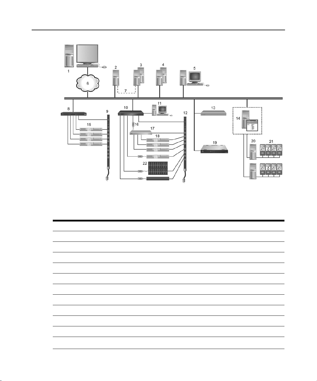
Figure 1.1 illustrates an example system configuration using the DSView 3 management software.
For information about the TCP ports that the DSView 3 software uses, see TCP and UDP Ports on
page 356.
Page 28
8 DSView 3 Software Ins taller/User Guide
Figure 1.1: Example System Configuration
Table 1.1: DSView 3 Software System Configuration Descriptions
Number Description Number Description
1 DSView 3 Software Client 12 Power Device
2 Hub DSView 3 Software Server 13 Generic Appliance
3 Spoke DSView 3 Software Servers (Optional) 14 Hypervisor Manager
4 External Authentication Servers (Optional) 15 Target Device
5 SNMP Manager (Optional) 16 IQ Module
6 TCP/IP 17 Cascade Switch
7 Replication 18 Target Devices
8 ACS Advanced Console Server 19 MergePoint SP Manager
9 Power Device 20 Hypervisor Server
10 DSR Switch 21 Virtual Machines
11
OSCAR® Interface
22 Blade Chassis
Page 29

CHAPTER
Installation
2
This chapter describes the following installation sequence:
• What you should do before installing the DSView 3 software
• Installing the DSView 3 software
• Configuring the DSView 3 software, plus considerations when upgrading
• Running the DSView 3 software, that is, start a client session
Final sections describe how to change your password, uninstall the software, end a DSView 3
software session and install Java.
About Installation
9
When the DSView 3 management software is installed, the DSView 3 software database and a hub
server are also installed on the dedicated server.
The DSView 3 software may be installed on a computer containing an existing DSView 2.x
software authentication server without causing any interference with the operation of the DSView
2.x software system. The DSView 2.x software authentication server and the DSView 3 software
may run on the same dedicated server at the same time.
Rebooting the dedicated server is not required prior to using the DSView 3 software.
Once the DSView 3 software is installed and you have configured the hub server, users may log in
at another computer as a DSView 3 software client, using a supported web browser.
You may also install the DSView 3 software on additional computers and configure them as spoke
servers. See Spoke Servers on page 72 and Installing the DSR Remote Operatio ns Soft w are on
page 21.
NOTE: A license key permits the operation of the DSView 3 software on the dedicated server. The license key
also specifies the number of clients that may use the software and the number of spoke servers allowed on a
system. See Licenses on page 54.
Minimum requirements for the DSView 3 software
The following are the minimum requirements for installing the DSView 3 software on a dedicated
hub server or a computer that will function as a DSView 3 software spoke server:
Page 30

10 DSView 3 Software Installer/User Guide
• For supported Windows and Linux systems: 2 GHz Pentium or equivalent processor
• For supported Solaris systems: 1 GHz UltraSparc III processor
• 4 GB of RAM - additional memory may be needed, depending on the number of plug-ins
installed and appliances supported
• 100BaseT NIC (1GByte LAN recommended)
• 10 GB of free disk space - additional disk space may be required for data logging and plug-ins
• One of the following operating systems:
• Windows
• Windows Server
®
2000 Server or Advanced Server with the latest service package
®
2003 Standard, Enterprise and Web Edition
• Windows Server 2008 Standard, Enterprise and Datacenter Edition
• Windows Web Server 2008
•Red Hat
®
Enterprise Linux, Version 4 (AS, ES and WS products)
• Red Hat Enterprise Linux, Version 5
•Sun
• Novell
NOTE: The DSView 3 software is also supported on any of these operating systems running as a guest OS in a
virtual environment. However, while the DSView 3 software is expected to function properly on a guest OS in the
virtual environment, there may be unknown performance implications.
®
Solaris™ SPARC 9 and 10
®
SUSE® Linux (x86) Enterprise Server 9 or 10
Before installing and configuring the DSView 3 software
Before installing the DSView 3 management software, install the managed appliance hardware.
If the computer will be a hub server, you will need the license key obtained from Avocent and
provide a username and password to use for initial log in.
If the computer will be a spoke server, you will need to identify the associated hub server and
provide the name/password of the hub server’s DSView 3 software administrator.
To prevent potential mouse conflicts, you may configure certain settings on each server connected
to a KVM switch or serial console appliance. For details, see the Mouse and Pointer Settings
Technical Brief, which is available on the DSView 3 software DVD and on the Avocent web site.
Installing the DSView 3 Software
The DSView 3 management software may be installed using the DSView 3 software DVD or by
downloading the software in a self-extracting .zip file from the Avocent web site.
Page 31

Chapter 2: Installation 11
NOTE: If you are upgrading the DSView 3 software from a previous version, it is strongly recommended that you
perform a database synchronization between the hub and spoke servers; see Replication on page 75. You
should also back up the hub server prior to upgrading the DSView 3 software; see Backing up and Restoring Hub
Servers Manually on page 69. Failure to perform synchronization and backup may have detrimental effects. A
backup should be performed both before the upgrade and immediately following the upgrade.
To install the DSView 3 software on a supported Windows system:
1. Log on to the dedicated server as Administrator.
2. To install from a DVD:
a. Insert the DSView 3 software DVD. An autorun file opens a menu of installation options.
b. Click Install DSView 3 Software.
-orIf autorun is not enabled, type
<drive:>\DSView\win32\setup.exe, where <drive:> is the
letter of your DVD drive.
A dialog box will indicate that the server will be verified to ensure it meets the minimum
requirements for installing the DSView 3 software.
To install from a downloaded file:
a. Using your web browser, download the DSView 3 so ftware from the Avocent web site.
Go to www.avocent.com and click the Support link. On the Technical Support page, click
the Product Upgrades link, then select DS Software Upgrades.
b. Double-click on the downloaded installation package (setup.exe). A dialog box will
indicate that the server will be verified to ensure it meets the minimum requirements for
installing the DSView 3 management software.
3. If the current or an earlier version of the DSView 3 software is already installed, the Installed
Product Found: Same Version message box will appear. Click OK to reinstall the DSView 3
software or Cancel to exit setup.
4. The Check for an UPDATED version window will open. (If the DSView 3 software is already
installed on the dedicated server, a message box will display. Click OK to close the box.)
a. Click Next to reinstall the software, or click Cancel to stop the reinstallation.
b. Click Check for UPDATES and then click Next to check the Avocent web site for the most
recent DSView 3 software installation package. Go to step 5.
-orClick Next to install the DVD or downloaded version of the DSView 3 software. Go to
step 6.
5. If a newer version of the DSView 3 software is found, an Update Available message appears.
a. Click OK to download the latest DSView 3 software installation package. The installation
will be cancelled and the server’s default web browser will launch and open in the Product
Upgrades and Options page of the Avocent web site.
-or-
Page 32

12 DSView 3 Software Installer/User Guide
Click Cancel to resume installation of the older version of the DSView 3 software. Go to
step 6.
b. Type your email address and password, and then click Submit to log in to the web site.
c. Download the DSView 3 software installation package, log out and close the web
browser. Return to step 2.
6. The Introduction window will open. Click Next.
7. The License Agreement window will open.
• If you accept the terms, click I accept the terms of the License Agreement and then click
Next. Go to step 8.
• If you do not accept the terms, click I do NOT accept the terms of the License Agreement.
A License Agreement Warning message box will appear.
• If you click Quit, the installation will exit without installing the DSView 3 software.
• If you click Resume, you will be returned to the License Agreement window.
The DSView 3 software license agreement may also be viewed from the User Login window
by clicking the Avocent DSView 3 End User License Agreement link. The agreement will
appear in a separate web browser window.
8. If the default TCP port used by the dedicated server hosting the DSView 3 software (TCP port
443) is not available, the Define Web Application Server TCP port window will open. Type the
port you want to use in the TCP port # field, then click Next. (Clicking Cancel exits the
Checking for an Updated version installation program.)
9. If the default TCP port used by the Avocent proxy server (TCP port 1078) is not available, the
Define TD (target device) Session Viewer Proxy TCP port window will open. Type the port
you want to use in the TCP port # field, then click Next.
10. If the default ports used by the SSH server and the Syslog server for data logging are not
available, appropriate windows will open. Type the port you want to use, then click Next.
11. The Choose Destination Location window will open.
a. Click Choose and use the Browse for Folder dialog box to select a directory in which to
install the DSView 3 software.
-orClick Restore Default Folder to restore the installation directory to the default
(C:\Program Files\Avocent DSView 3).
b. Click Install.
The Installing... window will open and display the progress of the installation. The software
will be installed in the specified folder, a Start - Programs - DSView 3 shortcut menu will be
generated and the DSView 3 software service startup will be verified.
If a previous version of the DSView 3 software already exists on the dedicated server, message
boxes may appear, prompting you to confirm overwriting existing file s. Click Yes to All.
Page 33

Chapter 2: Installation 13
12. When the software has finished installing, the Successful Service Startup message box will
appear. Click Continue.
13. The Installation Complete window will open.
• To begin configuration of the DSView 3 software, click Done; see Configuring the
DSV i ew 3 Software on page 14. A Security Alert dialog box will appear containing certificate information and a warning that the generator of the certificate is not trusted. This
occurs because the DSView 3 server certificate created when the server is installed is a
self-signed certificate. You may either import the certificate into the DSView 3 software
client web browser (choosing to trust the certificate) or obtain a server certificate from a
Certificate Authority (CA) trusted by the web browser.
• T o configure the DSV iew 3 software at a later time, cli ck X (Cancel) in the top right corner
of the window.
To install the DSView 3 software on a supported Linux or Solaris syste m:
1. Log in to the server as root.
2. Insert the DSView 3 software DVD into your DVD drive. If AutoMount is supported and
enabled, open a command window and continue with step 3.
If your system does not support AutoMount, issue the following command to mount the DVD
volume:
mount <device> <mount point>, where <device> and <mount point> are the names
of your server’s DVD Linux or Solaris device and mount point directory, respectively.
For example, to mount the first IDE cdrom on /media/cdrom, enter the command:
mount /dev/cdrom /media/cdrom
3. Enter the following command to access the readme file:
less /<mount point>/DSView/readme
For example, the following command accesses the readme file on the /media/cdrom mount
point.
less /media/cdrom/DSView/readme
4. Follow the instructions in the readme file.
Upgrading the DSView 3 Software
When upgrading to a newer version of the DSView 3 software, all DSView 3 servers should be
upgraded at the same time. The DSView 3 hub server should be upgraded first, followed by each
spoke server.
Before upgrading, a replication should be performed (see Replication on page 75), then a backup
immediately before and after upgrading the DSView 3 software (see Backing up and Restoring Hub
Servers Manually on page 69).
The firmware for the appliances may also need to be upgraded in order to support new functionality
in the DSView 3 software. The DSView 3 software should work with the existing firmware
Page 34

14 DSView 3 Software Installer/User Guide
revisions, but in cases where new functionality is not supported until the firmware is upgraded, the
DSView 3 software will indicate this in the GUI.
Recommended upgrade process
NOTE: In order to safely upgrade the DSView 3 software, and to provide for a roll-back path in case of upgrade
failures, perform each of the following steps. If your DSView 3 configuration does not include spoke servers, skip
steps that refer to spokes.
To upgrade the DSView 3 software:
1. Ensure that you are able to upgrade the hub server and any spoke servers during the same
upgrade time. The expected time to perform this procedure is 30 minutes. However, due to
differences in DSView 3 configurations and amounts of data, your time may vary.
2. Verify that the installer files for both the new and old versions (in case recovery is needed) are
available to you.
3. Perform a replication of all spoke servers. See Replication on page 75.
4. Backup all hub and spoke servers. See Backing up and Restoring Hub Servers Manually on
page 69. It is advised that all DSView 3 backup files be stored on an external device or network
drive.
5. Verify basic functionality by navigating to a few DSView 3 windows and launching sessions to
a few target devices.
6. Run the DSView 3 installer for the new version on the hub server.
7. Run the DSView 3 installer on all spoke servers.
NOTE: The hub server must be upgraded prior to the upgrading the spoke servers.
8. Verify basic functio nali ty again by navigating to a few DSView 3 windows and launching
sessions to a few target devices.
9. Perform another backup of the hub and spoke servers to have a baseline database of the
upgraded environment. See Backing up and Restoring Hub Servers Manually on page 69.
10. Run replication to validate that there are no errors. Errors will either be displayed in the status
panel for the replication task or in the Events Log. See Replication on page 75.
11. The firmware for the appliances may also need to be upgraded in order to support new
functionality in the DSView 3 software. See Upgrading fi rm ware on page 314.
12. Verify basic functionality one last time by navigating to a few DSView 3 window and
launching sessions to a few target devices.
Configuring the DSView 3 Software
After the DSView 3 software has been installed, it must be configured using a web browser.
Page 35

Chapter 2: Installation 15
During configuration, you specify whether the computer will be a hub server or a spoke server. If
this is your first DSView 3 server installation, hub should be selected in the Select DSView Server
Role window. The hub server should be installed before any spoke servers are added.
What you will need
If the computer will be a hub server, you will need the license key obtained from Avocent and
provide a username and password to use for initial log in.
If the computer will be a spoke server, you will need to identify the associated hub server and
provide the name/password of the hub server’s DSView 3 software administrator.
To configure the DSView 3 software:
1. If you are configuring the DSView 3 software during the installation process, you have already
clicked Done in the Launch Default Browser window.
If you quit after installing the DSView 3 software installation process (by closing the window),
select Start - Programs - Avocent DSView 3 - DSView Software.
2. A security alert box will appear containing certificate information. See Certificates on page 46.
3. The Select DSView Server Role window opens.
•Click Hub to assign the dedicated server as the hub server, then click Next. Go to step 3.
•Click Spoke to assign the dedicated server as a spoke server, then click Next. Go to step 8.
4. The Type in Master License Key window opens. Type the Avocent-provided license key for
the DSView 3 software hub server, then click Next. (DSView 3 software license keys prior to
version 3.0 are not valid.)
If you did not receive a license key, click the http://www.avocent.com/activation link to obtain
a license key.
If the entered license is already in use on another server, a license violation will occur when
you log in, and you must configure the server as a spoke server.
5. The Type in Initial Administrator Account window opens. Type a username, a password and
confirm the password of the user to whom you wish to give administrator privileges.
Usernames are case sensitive and may contain up to 64 characters. Click Next.
6. A Request in Progress message will appear. The license key will be installed and a DSView 3
software administrator account will be created. The built-in user groups will also be created.
7. The Completed Successful window will open when configuration is completed. Click Finish.
8. The User Login window will open in the DSView 3 Explorer.
You may now log in using the username and password specified during configuration.
If you chose to configure the server as a spoke server in the Select DSView Server Role window or
if you entered a duplicate software license key in the Type in Master License Key window,
continue with the following steps.
Page 36

16 DSView 3 Software Installer/User Guide
NOTE: The DSView 3 software versions of the spoke server and the hub server must match in order to register
the spoke server. For example, you may not register a spoke server running DSView 3 software version 3.0 with
a hub server running DSView 3 software version 3.2.
9. The Type in Hub Server Address and Port window will open. Type the address of the DSView
3 software hub server using standard dot notation (xxx.xxx.xxx.xxx) or type the DNS name in
the Address field. Click Next.
10. The Accept DSView Server Certificate window will open. Click Next to accept the certificate.
11. The Type in Hub Administrator Credentials window will open. Type a valid username and
password for a user with DSView 3 software administrator privileges on the DSView 3
software hub server. Click Next.
12. The Registering Spoke Server window will open with the message Request In Progr ess Please
Wait The configuratio n of the spoke server will be saved to the database of the hub server and
the spoke server’s certificates will be installed on the hub server.
13. The Completed Successful window will open when the spoke server has been added. Click
Finish.
Running the DSView 3 Software
DSView 3 software clients access the DSView 3 management software host using a supported web
browser. Any software required by the client, such as applets and the Java Runtime Environment
(JRE), will be automatically installed by the DSView 3 server host.
The DSView 3 software uses Secure Sockets Layers (SSL) encryption to send data between the
DSView 3 software host and the web browser on the client to ensure data integrity and privacy.
When a user attempts to log in to a DSView 3 software client session, the authentication service
configured in the DSView 3 software by the DSView 3 software administrator verifies the
credentials of the user. Security alerts related to the certificates on the DSView 3 software host may
appear. See Certificates on page 46.
Minimum client requirements
The following are the minimum requirements for a DSView 3 software client:
• 1 GHz Pentium or equivalent processor
• 512 MB of RAM
• 10 or 100BaseT NIC (100 recommended)
• XGA video with graphics accelerator
• Desktop size setting of at least 800 x 600
• Color palette of at least 256 colors
• One of the following operating systems:
• Windows 2000 Workstation, Server or Advanced Server with the latest service package
• Windows XP Home Edition or Professional
Page 37

• Windows 2003 Server Standard, Enterprise or Web Edition
• Windows Vista Ultimate or Business
• Red Hat Enterprise Linux, Ve rsion 4 (AS, ES and WS products)
• Red Hat Enterprise Linux, Version 5
• Sun Solaris SPARC 9 and 10
• Novell
SUSE Linux (x86) Enterprise Server 9 or 10
• Macintosh OS X version 10.4 and later
• Adobe
®
Flash Player version 9.0 or later
• One of the following browsers:
• Microsoft
•Firefox
®
Internet Explorer 6 or 7
®
2 or 3
Install the latest updates and service packs available for your browser.
If you are using Firefox, the Video Viewer and the Telnet Viewer clients require Java; see Java
Installation on page 19.
Opening a client session
Before opening a client session
Chapter 2: Installation 17
• Enable cookies and JavaScript on the client’s web browser.
• Configure the web browser. If you are using Internet Explorer, see Internet Explorer Consider-
ations on page 42.
To open a client session:
NOTE: If DSView 3 Software Client Certificate Authentication or DSView 3 Software Client Integrated Windows
Authentication is being used, the user will not be required to log in. See Certificates on page 46.
1. From the DSView 3 software client web browser, enter the URL of the server host in the
address bar in the format:
https://<servername>/dsview
In this case, <servername> is the DNS name of the host system, or the IP address in standard
dot notation (xxx.xxx.xxx.xxx).
NOTE: To avoid multiple security warnings, enter the DNS name.
-orIf you are opening the session on the DSView 3 server, you may select Start - Programs -
Avocent DSView 3 - DSView Software.
2. Accept all security alerts that may appear as the client computer connects to the DSView 3
server. The DSView 3 Explorer User Login window will open.
Page 38

18 DSView 3 Software Installer/User Guide
If an RSA SecurID external authentication service has been added to the DSView 3 software,
see RSA SecurID login below for the login procedure.
3. Type a valid username and password in the fields provided.
Depending on the settings specified by the administrator, you may be required to change your
password before being allowed to complete the login process. See Adding User Accounts on
page 231.
4. Click Login. The window that appears depends on the rights assigned to the DSView 3 user
that is logging in.
If the client machine uses an onboard video controller and experiences video problems, be sure the
BIOS is updated to the latest version.
RSA SecurID login
When an RSA SecurID external authentication service has been added to the DSView 3 software,
the login credentials include a username and a passcode. The passcode includes a PIN and an RSA
SecurID tokencode. The login request is sent to the RSA Authentication Manager. Depending on
the user configuration and state on the RSA Authentication Manager, the user may be prompted for
a second successive tokencode.
The user configuration also specifies how the 4-6 digit PIN will be generated:
• User defined - the user must enter a PIN
• System generated - the user cannot enter a PIN; it must be generated by the RSA server
• User selectable - the user may choose to enter a PIN or allow the RSA server to generate it
If a PIN has not yet been assigned to the user or if security policy requires a PIN change, the user
will be prompted accordingly. If the RSA server generates the PIN, the user will be given a brief
interval to memorize it.
Regaining access
If access to a DSView 3 software system is lost, see Regaining Access to the DSView 3 Software on
page 389.
Uninstalling the DSView 3 Software
To uninstall the DSView 3 software on a supported Win dows system:
1. Select Start - Settings - Control Panel. The Control Panel will appear.
2. From the Control Panel, click Add/Remove Programs. The Add/Remove Programs dialog box
will appear.
3. Select Avocent DSView 3 and then click Change/Remove. The Uninstall Avocent DSView
window will open.
4. Click Uninstall.
Page 39

To uninstall the DSView 3 software on a supported Linux or Solaris system:
1. Log in to the server as root.
2. Insert the DSView 3 software DVD into your DVD drive. If AutoMount is supported and
enabled, open a command window and continue with step 3.
-orIf your system does not support AutoMount, issue the following command to mount the DVD
volume:
of your server’s DVD Linux or Solaris device and mount point directory, respectively.
For example, to mount a DVD which is the second IDE unit on /media/cdrom, enter the
command:
mount /dev/cdrom /media/cdrom
3. Enter the following command to access the readme file.
less /media/cdrom/DSView/readme
Follow the instructions in the readme file.
mount <device> <mount point>, where <device> and <mount point> are the names
Closing a DSView 3 Software Session
Files are copied to DSView 3 software clients when you log in to the DSView 3 software. When
using Internet Explorer, temporary files may be removed by selecting the Delete Temporary
Internet Files command and active web components may be uninstalled by selecting the Remove
Objects command. See the Internet Explorer documentation for more information.
Chapter 2: Installation 19
To close a DSView 3 software session:
From the DSView 3 Explorer, click LOGOUT or the logout icon.
Java Installation
On non-Windows clients, the Video Viewer, Telnet and VNC Viewers require Java version 1.5.
The Telnet/SSH applet may work with other versions; the Video Viewer requires that version.
On Windows clients, Java is required to run the Avocent Telnet/SSH Viewer. If the Win32 PuTTY
Telnet/SSH Viewer is selected in the user’s profile, then Java is not required on the client. On a
Windows client, it is recommended that the JRE (Java Runtime Environment) be installed in the
C:\Program Files\ location. If your system automatically installs programs in another location, you
may not be able to launch the Video Viewer. In this case, you can configure Java to find the JRE.
To configure Java to find the JRE:
1. Access the Java Control Panel.
2. Select the Java tab.
3. In the Java Application Runtime Settings panel, click View.
4. Change the path to the installed JRE.
Page 40

20 DSView 3 Software Installer/User Guide
5. Click OK.
For Windows, Linux and Solaris operating systems, the DSView 3 software client automatically
downloads and installs the JRE the first time it is needed. For Macintosh operating systems, you
must update Java and install the JRE using the Macintosh software updates. Refer to the Macintosh
operating system documentation for more information.
To install the JRE on a Windows client:
1. In a DSV iew 3 software Units V iew window (see Accessing Units View windows on page 106),
click an Action link.
2. A window will open, containing a link for downloading the JRE installer. Download the JRE
installer, then close all browser windows.
3. Click on the JRE icon to launch the installer.
4. Restart the browser, and click an Action link.
To install the JRE on a Linux or Solaris client:
NOTE: Only one version of the JRE can be installed in the browser for DSView 3 software support. Depending
on your system’s configuration, you may have to log in as the root user to install the JRE. Contact your system
administrator if you need help with installing software as the root user.
1. In a DSV iew 3 software Units V iew window (see Accessing Units View windows on page 106),
click an Action link.
2. A window will open, containing a link for downloading the JRE installer. Download the JRE
installer, then close all browser windows.
3. Run the installer.
4. Restart the browser, and click an Action link.
Avocent Viewer Plug-in Installation
On Windows clients, the Video Viewer, Telnet and VNC Viewers require the Avocent Viewer
Plug-in. If you are using Firefox 2 or Internet Explorer, the plug-in downloads automatically from
the browser window. If you are using Firefox 3, additional set up is required.
To install the Avocent Viewer Plug-in when using Firefox 3 on a Windows client:
1. In a Units View window containing the target device you want to access (see Accessing Units
View windows on page 106), click an Action link.
2. The Installing Avocent Viewer Plug-in pop-up window opens. Click Download Avocent
Viewer Plug-in.
3. Click Save, then open the saved file. The Firefox downloads window opens.
4. Click OK, the follow the instructions in the installer wizard to install the file.
Once the installation is complete, the viewer session starts automatically.
Page 41

Installing the DSR Remote Operations Software
NOTE: Installing and using the DSR Remote Operations software is optional.
If your DSView 3 software system includes DSR1021, 1022, 1024, 1020, 1030, 1031, 2020, 2030,
2035, 4020, 4030, 8020, 8030 or 8035 switches, you may use the DSR Remote Operations software
for switch access using a dial-up point to point protocol (PPP) modem connection when an Ethernet
connection is unavailable.
See DSR Remote Operations Software on page 364 for information about installing and using the
DSR Remote Operations software.
Chapter 2: Installation 21
Page 42

22 DSView 3 Software Installer/User Guide
Page 43

CHAPTER
3
When a user has been logged in and authenticated, the Avocent DSView 3 Explorer window opens.
From the DSView 3 Explorer window, you may view, access and manage units.
23
DSV iew 3 Explorer Windows
Figure 3.1: Example Avocent DSView 3 Explorer Window Areas
Page 44

24 DSView 3 Software Installer/User Guide
Table 3.1: DSView 3 Explorer Window Area Descriptions
Number Description
1
2
3
4
5
Top option bar - Use the top option bar to bookmark a DSView 3 software window, refresh a
window display, print a page, log out of a software session or access online help. The name of the
logged in user appears on the left side of the top option bar.
Tab bar - Use the tab bar to display and manage units, user accounts, reports, system settings and
session profiles.
Top navigation bar - The selections in the top navigation bar vary, depending on the active tab in
the tab bar. Topics relevant to each selection display in the side navigation bar.
Side navigation bar - Use the side navigation bar to select system information to display or edit in
the content area. The side navigation bar contains arrows that affect its display.
Content area - The information specified by the tab bar, top navigation bar and side navigation bar
selections is displayed and changed in the content area.
Accessing Target Devices
Target devices (TDs) that may be accessed system-wide are displayed in a Units View window.
You may initiate a session with a target device from a Units View window by clicking the link in
the Action column. See Units View Windows on page 103.
You may also initiate a session with a target device from a Unit Overview window. See Unit
Overview Windows on page 112.
For information about controlling the power of target devices attached to power devices, see Power
Control of Devices Attached to Power Devices on page 169.
Using the Side Navigation Bar
The side navigation bar is used to display windows that specify settings or perform operations. The
contents of the side navigation bar varies, depending on the tab and top navigation bar selections
and the window that is displayed.
Page 45

Figure 3.2: Example Side Navigation Bar
Unit Views
Target Devices
Appliances
All
ACS48
DSR1031
DSR8035
Recently Accessed
Active Sessions
.
.
.
3
4
1
2
Table 3.2: Side Navigation Bar Descriptions
Number Arrow Description
Chapter 3: DSView 3 Explorer Windows 25
1
2
3 Collapse Node - Click this arrow to collapse an opened tree branch and its links.
4 Expand Node - Click this arrow to expand a closed tree branch and display its links.
Expand All Nodes - Click this arrow in the upper right corner to expand all nodes and
display additional links.
Collapse All Nodes - Click this arrow in the upper right corner to collapse all nodes
and their links.
You may choose whether an expanded node will collapse when another Expand Node arrow is
selected. See Changing user options on page 36.
Clicking on a link that does not contain an arrow will display its corresponding window. So me
windows contain additional links, which may display another window and a side navigati on bar
with different content.
Page 46

26 DSView 3 Software Installer/User Guide
Using Windows
Sorting information in a window
The order of rows in a list may be changed by clicking the heading of one of the displayed columns.
When you click a column heading, the order of the list rows will change to alphabetically
ascending, based on that column. If you click the column heading a second time, the order will
change to an alphabetically descending order. An up arrow indicates ascending order and a down
arrow indicates descending order.
If you are using the topology feature in a Units View window, see Topology view on page 104 for
sorting criteria.
Filtering information in a window
Some DSView 3 software windows allow you to filter list information by providing a text string
that will be used to retrieve matching items. Filtering is useful if you have many target devices or
other items that extend over many pages. Windows that allow filtering contain a text field and a
Filter button in the content area, as shown in Figure 3.1 on page 23.
Filtering is performed either over the entire list of items or of specified columns, and can provide a
shorter, more exact list of items. When filtering is performed, each row and column is searched for
the specified text string. For example, you may wish to perform filtering to list only DSR1031
switches in the Name column, target devices with KVM connections in the Action column, idle
ACS console servers in the Status column and so on. Additionally, from a Units View window, you
can use the Custom Fields and Filter link to exclude columns from the filter and provide a more
exact list of filtered items. See Using the Customize link in windows on page 28.
When the topology feature is enabled in a Units View window, both parent and child units will
display in the filtered view. For example, if you filter for a child named target device 1 that is
attached to a DSR1031 switch, target device 1 will appear below the DSR1031 switch in the
filtered view.
When filtering, you may use an asterisk (*) before and/or after text strings as a wildcard. For
example, typing
beginning (such as emailserver, emailserverbackup). Typing
display items containing emailserver in any part of the name (such as emailserver,
emailserverstore, tdemailserver, tdemailserver1).
Table 3.3 lists the ways you may specify text strings for filtering.
emailserver* and clicking Filter will display items with emailserver at the
*emailserver* and clicking Filter will
Page 47

Table 3.3: Filter Text Strings
Typed in the Filter Field Results
Entering a string displays a filtered list of items that contain the ‘word’ (that is, it
will find matching strings that are followed by anything other than a letter or
<String>
“<String>”
<String1> AND <String2>
<String1> OR <String2>
(<String>)
number). For example, typing email will list any items that contain the string
email, followed by a space or punctuation mark.
If you enter multiple words separated by spaces but without logical operators,
OR is assumed, and each word is treated separately . For example, typing email
server will display items containing email or server.
Surrounding the string with quotation marks displays a filtered list of items
containing the exact string, including spacing and punctuation. For example,
typing “email server” will display items that contain email server. The DSView
3 software will provide a closing quotation mark if it is omitted.
Using the AND logical operator displays the items that contain both strings. For
example, typing email and server will display items named email-server-3,
email-server-2, server email and so on.
Using the OR logical operator displays the items that contain at least one of the
strings. For example, typing email or server will find any items that contain the
string email or the string server.
Parentheses may be used to override the default (left to right) order of
precedence during evaluation of a filter string.
For example, searching for email and server or service would be the
equivalent of ((email and server) or service), which may not be the intended
search. The user may choose instead to change the order of precedence by
grouping the search terms with parentheses, such as (email) and (server or
service).
Chapter 3: DSView 3 Explorer Windows 27
Preceding the string with NOT displays all items that do not contain the string.
NOT <String>
For example, typing not email will display all items except those containing
email (email, email server, email-server-1 and so on will not display).
To filter the list in a window:
1. In a window containing a Filter field, type a text string in the field. Searches are not case
sensitive.
2. Click Filter. A filtered list of the information in the window will be displayed.
3. Click Clear to return to a non-filtered list.
Saving information in a window
When you change information in a window, you must click Save in order to apply the changes. By
default, a message box will appear if you click Close or try to exit the window by clicking a link in
the top bar, top navigation bar or side navigation bar without first clicking Save.
Page 48

28 DSView 3 Software Installer/User Guide
Clicking OK in the message box will exit the current window without saving the changes. If you
want to save the changes you have made, click Cancel in the message box, then click Save in the
window.
You may choose whether you will be reminded to save changes made in windows before exiting
them. See Changing user options on page 36.
Using the Customize link in windows
Windows that contain a Customize or Customize Fields and Filter link allow you to change the
following information:
• The number of items displayed per page in the window
• Which columns of information are displayed in Units View windows
• Which columns are included in a filter from a Units View window (available from the
Customize Fields and Filter link only)
By clicking the Customize link, you can also show units that have been hidden in a Units View
window.
NOTE: If you are in a Units View window, the link is displayed as “Custom Fields and Filter” and this window
contains additional filtering options. On any other window, the link is displayed as “Customize”. The term
“Customize link” is used throughout this document to refer to both links.
The items available for customizing and methods for changing them will vary, depending on the
window being customized. Although the items that appear in windows may vary, the items th at do
appear are modified identically regardless of the window in which you clicked the Customize link.
DSView 3 software administrators may also configure the default display for custom izable
windows, that is, which columns will be displayed and how many items will be displayed per page
by default. The default values will be used by all new users and by existing users who have not
already customized their views.
To customize a window using the Customize link:
1. In a window containing a Customize link in the upper right corner, click the link. A View
Customization window will open.
2. Add, remove or move fields in the window display:
• To add one or more fields to the window display, select the fields in the Available Fields
list, then click Add. The fields will be moved to the Fields to Show list.
• To remove one or more fields from the window display, select the fields in the Fields to
Show list, then click Remove. The fields will be moved to the Available Fields list.
• T o change the order that fields display from left to right in the window, select one or more
fields in the Fields to Show list. Use the up or down arrow to change its order in the list.
3. To specify the number of items that appear in a window, use the arrow keys in the Items per
Page field to select a number or type a number (1-2000). In Units View windows that have the
Page 49

topology view enabled, the number of items per page includes children, even if the display is
collapsed and the children are not visible.
4. To show hidden items in a Units View window (see Showing and hiding units on page 107).
a. Check the Show hidden items checkbox.
b. Select Visibility from the Available Fields column, and then click Add. Visibility will
move to the Fields to Show list.
5. To show group descendants in windows that display unit groups (see Unit group hierarchy on
page 212), click the Show group descendants checkbox.
6. To expand a topology view automatically in a Units View window (see Topology view on
page 104), click the Expand view automatically checkbox.
7. (Units View windows only) To specify which fields are included in a filter, select the field(s)
from the A vailable Fields list and click the Add button. T o remove fi elds from a filter , select the
fields from the Filter on these fields list and click Remove.
8. To set the Fields to Show and List Items as the default, click Set as Default. This button will
appear only if you are a DSView 3 software administrator. Yo u will be prompted to confirm
setting these values as the default. Confirm or cancel.
9. Click Save and then click Finish. The window being customized will open with the changes.
Displaying pages
Chapter 3: DSView 3 Explorer Windows 29
Multiple page windows contain navigation buttons which may be used to quickly mo ve among
pages.
Table 3.4: DSView 3 Explorer Page Navigation Buttons
Button Description
|< First Page - Navigates to the beginning of a list displayed in a window.
<< Previous Page - Navigates to the previous page of a list displayed in a window.
>> Next Page - Navigates to the next page of a list displayed in a window.
>| Last Page - Navigates to the end of a list displayed in a window.
The page navigation buttons are enabled only if there are enough pages available to make them
necessary.
The number of items that display in a window page is specified by using the Customize link (see
Using the Customize link in windows on page 28). If a page’s content cannot fit vertically and/or
horizontally in the window, scroll bars will appear. The current page and total number of pages
appear in the top left corner of the window.
Many operations allow you to select all items on a page by enabling a checkbox located to the left
of the column headings in the window. Enabling this checkbox selects all the items listed on a page
Page 50

30 DSView 3 Software Installer/User Guide
(whether or not the entire page is visible). However, for multi-page displays, items listed on other
pages will not be included in the selection.
The only time you can select all items on all pages of a multipage display in one step is when you
are setting access rights from a Units View windows. For this operation, if you click Rights in a
Units View window with no units selected, all units on all pages will be affected by the operation.
Bookmarking a window
Many windows contain a bookmark icon and text in the top option bar. Bookmarking a window
will add a link to the window in the Favorites menu. You may select the link at any time to quickly
access the bookmarked window.
If you bookmark a window and information related to the window changes, this new informati on
will appear in the window when you next display the bookmarked window. For example, if you
bookmark the Recently Accessed window and then access other units, the bookmarked window
will contain these other units the next time you display the bookmarked page.
If you click BOOKMARK or the bookmark icon after the DSView 3 server session has timed out,
the User Login window will open and you must log in again. After you log in, you will be
redirected to the bookmarked page.
To bookmark a window:
1. In the top option bar, click BOOKMARK or the bookmark icon. The Add Favorite dialog box
will appear.
2. Optionally, type a name for the window. You may also click Create in to create or specify a
folder in which to place the window.
3. Click OK to close the Add Favorite dialog box.
Printing a window
All windows contain a print icon and text in the top option bar. When you print a window, all the
information on the page is printed, not just the visible portion.
To print a window:
1. In the top option bar, click PRINT or the print icon. The Print dialog box will appear.
2. Specify options to use, then click Print to print the window and close the Print dialog box.
Refreshing a window
A window may be refreshed at any time by clicking REFRESH or the refresh icon in the top option
bar.
By default, status information automatically refreshes every 30 seconds. This interval may be
changed or disabled. See Changing user options on page 36.
Page 51

Using keyboard commands
In addition to using a mouse, certain keyboard commands may be used to select and change items
in windows.
Table 3.5: General Keyboard Commands
Key Description
Tab Transfers focus to the next control in the window, including the calendar
Shift-Tab Transfers focus to the previous HTML control
Table 3.6 lists the keyboard commands that may be used when a calendar is enabled and has focus.
Table 3.6: Calendar Keyboard Commands
Key Description
Enter or Space Displays or closes the calendar.
Esc Closes the calendar.
Page Up Decrements the month by one month and selects the first day of the month.
Chapter 3: DSView 3 Explorer Windows 31
Page Down Increases the month by one month and selects the first day of the month.
Right Arrow
Left Arrow
Up Arrow
Down Arrow
Increments the day by one day. If the last day of the month is selected and the Right
Arrow key is pressed, the month is incremented to the next month.
Decrements the day by one day. If the first day of the month is selected and the Left
Arrow key is pressed, the month is decremented to the previous month.
Decrements the weekday by one week. If the first weekday type of the month is selected
and the Up Arrow key is pressed, the month is decremented to the previous month.
Increments the weekday by one week. If the last weekday type of the month is selected
and the Down Arrow key is pressed, the month is incremented to the next month.
Table 3.7 lists the keyboard commands that may be used when a spinner is enabled and has focus.
Table 3.7: Spinner Keyboard Commands
Key Description
Up Arrow Increments the spinner number by one
Down Arrow Decrements the spinner number by one
Page 52

32 DSView 3 Software Installer/User Guide
Page 53

CHAPTER
4
This chapter describes basic operations and settings, including global system properties, profiles,
built-in user groups and preemption levels.
DSView 3 Help
NOTE: The DSView 3 Help section only applies to DSView 3 software versions 3.5 or later.
The DSView 3 help is hosted on the Avocent web site. If you do not have continuous access to the
Internet, you may wish to install the help on the local DSView 3 server.
NOTE: Help for DSView 3 software plug-ins is automatically installed on your local server and is not available
from the Avocent web site.
33
Basic Operations
Configuring the DSView 3 help location
DSView 3 administrators can change the DSView 3 help location at any time. Help is configured
independently for each DSView 3 hub and spoke server.
To configure the DSView 3 help location:
1. Click the System tab, then click DSView 3 Server.
2. Click Properties - Help Configuration in the side navigation bar.
3. Specify the location of the help that will be accessed each time Help - DSView 3 Management
Software Help is clicked.
Select View help from the Avocent web site to access the latest help for your DSView 3
software version from the Avocent web site (Internet connection required).
-orSelect View help from this DSView 3 server help location to access the downloaded help from
your local server. Complete the following procedure for Installing DSView 3 help on a local
server.
4. Click Save.
Page 54

34 DSView 3 Software Installer/User Guide
NOTE: If your DSView 3 software version is several versions prior to the current version, the help may not be
available on the Avocent web site. In this case, when you access the help from the web, you are prompted to
save a .zip file of the help to the local device. Complete the Installing DSView 3 help on a local server procedure.
Installing DSView 3 help on a local server
You can automatically download the help from the Avocent web site using the DSView 3 software,
or you can visit www.avocent.com/dsview3help to browse for the appropriate version and save a
.zip file of the help to local media.
To download or update DSView 3 help on the local server:
1. Click the System tab, then click DSView 3 Server.
2. Click Properties - Help Configuration in the side navigation bar.
3. Click the Download Latest Help button. The DSView 3 Help Download Wizard opens.
4. Select From the Avocent web site to download the latest help for your DSView 3 software
version from the Avocent web site.
-orSelect From a local device to retrieve the help from local media. To specify the location, click
Browse or type the path in the field.
5. Click Next.
6. The Completed Successful window opens. Click Finish.
NOTE: If you reinstall or upgrade the DSView 3 software, the DSView 3 help location is reset to From the
Avocent web site. Complete the Installing DSView 3 help on a local server procedure if you want to access the
help from the local server.
Global System Properties
Global system properties affect all DSView 3 servers in the system. That is, when global system
properties are changed on a DSView 3 server, the next replication operation will apply those
changes to all other DSView 3 servers in the system; see Replication on page 75.
Global system properties include:
• Video session properties - see Video Viewer session properties on page 253
• User credential properties - see Specifying a user certificate on page 38 and Specifying an SSH
key on page 39
• Legal notice - see Legal Notice on page 35
• Target device naming - see Target Device Naming on page 152
• Automatic inheritance - see Automatic Inheritance for Group Memberships and Properties on
page 135
Page 55

Legal Notice
You may enable or disable the display of a legal caption and disclaimer prior to users logging in to
the DSView 3 software. When enabled, the legal disclaimer is displayed every time a user logs in.
The legal notice feature affects all DSView 3 servers in the system after replication; see Replication
on page 75.
Only DSView 3 software administrators may configure the legal notice.
To enable or disable and configure the legal notice:
1. Click the System tab.
2. Click Global Properties in the top navigation bar.
3. Click Legal Notice in the side navigation bar. The DSView 3 System Logon Legal Notice
window will open.
4. To enable the legal notice display:
a. Check the Enable Legal Notice checkbox.
b. Enter up to 80 characters in the Caption field. This is a required field.
c. Enter up to 512 characters in the Text field. Carriage returns may be used to separate lines.
This is a required field.
d. Click Save.
5. To disable the legal notice display, uncheck the Enable Legal Notice checkbox and then click
Save.
Chapter 4: Basic Operations 35
PCI Compliance Configuration
The DSView 3 software may be configured as Payment Card Industry (PCI) compliant. When PCI
compliance is enabled, three settings are affected:
• Browser caching of secure web pages is disabled. This setting prevents the potential loss of
confidential client data; however, this setting may not work effectively if olde r browsers are
used.
• The browser prompt to save passwords is disabled. This setting prevents the potential loss of
confidential client data.
• Weak SSL ciphers are disabled. This setting prevents th e potential loss of data integrity.
These three settings may be enabled at once on the Global Properties page, or may be enabled/
disabled individually.
Page 56

36 DSView 3 Software Installer/User Guide
NOTE: When PCI compliance is enabled, the exporting of the DSView 3 server CSR files, PEM certificates and
SSH keys does not submit the request to the client's browser; instead the files are saved in the DSView 3 server
user's home directory. The CSR filename is the name of the DSView server with extension .p10, the PEM
certificate filename is DSView System Certificate.pem, and the SSH key filename is DSView System
Certificate.pub. For example, if the server is running on Windows XP and the name of the server is WinXPServer ,
the files are saved to [rootdrive]\Documents and Settings\[username]\ and the names are:
- CSR file = WinXPServer.p10
- PEM certificate = DSView System Certificate.pem
- SSH key = DSView System Certificate.pub
To enable PCI compliance:
1. Click the System tab.
2. Click Global Properties in the top navigation bar.
3. Click PCI Compliance in the side navigation bar. The PCI Compliance Properties window will
open.
4. To enable PCI compliance, select Make DSView Server PCI Compliant. Click Save.
5. Restart the DSView 3 server.
6. Run the MSI installer to push the Video Viewer files to the Internet Explorer clients accessing
the DSView 3 software; follow the procedure in Managing ActiveX
NOTE: The PCI compliance setting is not replicated to other DSView 3 servers. You must configure PCI
compliance settings individually for each server that you wish to be PCI compliant.
®
controls on page 43.
Profiles
Profile information contains features and tasks that may affect actions when using the DSView 3
software. These include:
• User options
• Color scheme
• Changing a password
• Choice of serial session application
• Specifying a user certificate
• Specifying a user SSH key
NOTE: You may also set up KVM session profiles for use with the Video Viewer; see KVM Session Profiles on
page 254.
Changing user options
To change user options:
1. Click the Profile tab. The Options window will open.
2. In the Navigation Tree Behavior area, select one option:
Page 57

• If you select Automatically collapse navigation tree nodes, a currently-expanded tree node
will be collapsed when you select another tree node.
• If you select Preserve navigation tree state, a currently-expanded tree node will remain
expanded when you select another tree node.
• If you select Automatically fully expand navigation tree nodes, all tree nodes will be
expanded. This is equivalent to clicking the Expand All Nodes arrow in the side navigation
bar; see Using the Side Navigation Bar on page 24.
3. Enable or disable prompts when leaving pages with unsaved changes:
• Check Skip prompt when leaving pages with unsaved changes, if you do not want a
message box to prompt you to save modified information when you leave a window.
• Uncheck Skip prompt when leaving pages with unsaved changes if you want a message
box to prompt you to save modified information when you leave a window.
4. Select a refresh rate or Never. By default, windows automatically refresh every 30 seconds. If
you select Never, windows will only be refreshed when you click the REFRESH icon or text in
the top option bar.
5. Click Save.
Changing the color scheme
When the color scheme is changed, it is changed only for the logged in user.
Chapter 4: Basic Operations 37
To change the color scheme:
1. Click the Profile tab.
2. Click Preferences in the top navigation bar.
3. Click Color Scheme in the side navigation bar. The Color Scheme window will open.
4. Click a color scheme to use. If the System Colors scheme is selected, the DSView 3 Explorer
window will match the user’s desktop color scheme.
5. Click Save. The color scheme will be applied to the DSView 3 Explorer window.
Changing your password
When the DSView 3 software internal authentication service is used, user accounts will indicate if
users are allowed to change their password; see User account restrictions and expiration settings
on page 236.
By default, passwords must contain at least three characters and will never expire. A different
minimum character length and an expiration date may be configured; see DSView 3 software
internal authentication service on page 80.
To change your password:
1. Click the Profile tab.
2. Click Preferences in the top navigation bar.
Page 58

38 DSView 3 Software Installer/User Guide
3. Click Change Password in the side navigation bar. The Change Password window will open.
4. Type your current password.
5. Type and confirm the new password.
6. Click Save.
Choosing the serial session application
You may specify the application to be used for serial sessions to target devices.
• DSView 3 software Telnet Viewer (Avocent Session Viewer)
• Win32 PuTTY Telnet/SSH application
• Third party application
NOTE: If you use a third party Telnet application, the first time you attempt to launch a session, you will be
prompted to confirm the use of that application. If you do not confirm the use of that application, the session will
not be launched.
NOTE: Only the DSView 3 software Telnet Viewer is supported on Macintosh system clients.
To specify the serial session application:
1. Click the Profile tab.
2. Click Applications in the side navigation bar.
3. Check the checkbox for the application you want to use for serial sessions.
4. If you check 3rd Party Application, enter the path and executable name of the application
(maximum 256 characters) in the Serial Application field.
Specify any of the following parameters (up to 128 characters) in the Command Line
Arguments field. When the serial session is launched, the actual values will be substituted.
%ADDRESS% - The IP address will be substituted.
%PORT% - The port number will be substituted.
%TNAME% - The target name will be substituted.
If the third party application does not automatically launch a command window, check the
Launch in Command Window checkbox.
5. Click Save.
Specifying a user certificate
This property may be changed only for internal authentication users. See DSView 3 software
internal authentication service on page 80.
A user may specify a certificate if the administrator has allowed it; see the procedure below. If the
system certificate policy is enabled for user certificates (see System certificate policy and trust
store on page 47), the user certificate used at login must meet the policy requirements.
Page 59

As an alternative, the administrator may specify the certificate in the user account properties. See
User certificates on page 235.
To enable user settable certificates:
NOTE: Only DSView 3 software administrators may access this procedure.
1. Check the Allow user to set own certificate checkbox.
2. Click Save.
To specify a user certificate:
NOTE: A user may access this procedure only if a DSView 3 software administrator has allowed it.
1. Click the Profile tab. Preferences will automatically be selected in the top navigation bar.
2. Click Credentials in the side navigation bar, then click Certificate.
3. Type the path and name of the certificate or browse to the certificate location.
4. Click Save. An updated Certificate window will open.
Specifying an SSH key
A user may specify an SSH key if the administrator has allowed it.
As an alternative to this method, the administrator may specify the SSH key in the user account
properties. See User SSH key on page 235.
Chapter 4: Basic Operations 39
To enable user settable SSH keys:
NOTE: Only DSView 3 software administrators may access this procedure.
1. Click the System tab.
2. Click User Credential Properties in the side navigation bar.
3. Check the Allow user to set own SSH key checkbox.
4. Click Save.
To specify an SSH key:
NOTE: A user may access this procedure only if a DSView 3 software administrator has enabled it.
1. Click the Profile tab. Preferences will automatically be selected in the top navigation bar.
2. Click Credentials in the side navigation bar, then select SSH Key.
3. T y pe the 1-256 character name of the file containing the public SSH key that was generated by
a third party key generator or browse to the file location.
4. Click Save. An updated SSH Key window will open. The SSH key file will be uploaded to the
DSView 3 server for use in authenticating the user.
Page 60

40 DSView 3 Software Installer/User Guide
Software
Administrator
User
Administrator
Appliance
Administrator
Auditors
Users
Enabling user credential caching
User credential caching provides a single sign-on method for accessing units supported by certain
plug-ins. If enabled, the credentials used to log in to the DSView 3 software are maintained in a
secure internal cache. A supported plug-in, such as the Virtualization plug-in, can retrieve these
credentials to log in to connected units.
To enable user credential caching:
NOTE: Only DSView 3 software administrators may access this procedure.
1. Click the System tab.
2. Click User Credential Properties in the side navigation bar.
3. Check the Enable credential caching checkbox.
4. Click Save.
Any currently logged in users must log out and log in again for their credentials to be cached.
Built-in User Groups
When a user account is added to the DSView 3 software system, the user may be assigned to any of
the following built-in user groups:
• DSView 3 software administrators
• Appliance administrators
• User administrators
• Auditors
•Users
Table 4.1 lists the operations allowed for the built-in user groups.
Table 4.1: Built-In User Group Allowed Operations
Built-In User Group
Operation
Configure DSView 3 software system-level settings Yes No No No No
Add, change, import and delete DSView 3 software Yes Yes No No No
Backup and restore the DSView 3 software database Yes No No No No
Register a spoke server Yes No No No No
Page 61

Chapter 4: Basic Operations 41
Software
Administrator
User
Administrator
Appliance
Administrator
Auditors
Users
Table 4.1: Built-In User Group Allowed Operations (Continued)
Built-In User Group
Operation
Add, change and delete units Yes No Yes No No
Add, change and delete unit groups Yes Yes Yes No No
Configure access rights Yes Yes No No No
Add, change and delete sites, departments and locations Yes No Yes No No
Add, change and delete external authentication services Yes Yes No No No
Add, change, delete user accounts and user-defined user
groups
All event-related operation Yes No No Yes No
Change your own password Yes Yes Yes Yes Yes
In addition to the built-in user groups, the DSView 3 software supports user-defined user groups;
see Grouping Units on page 205.
Preemption Levels
The preemption level of users determines whether they may interrupt or disconnect another user’s
serial or video (KVM) session with a target device. This also applies to virtual media sessions,
which are initiated from the Video Viewer.
DSView 3 software administrators and user administrators may specify the preemption level for
user accounts or user-defined user groups when an account or group is created. The preemption
level may be changed later. See Preemption level on page 237 or User Group Properties on
page 245.
By default, the preemption level used by the DSView 3 management software (the effective user
preemption level) is the highest level of all of the user groups to which the user belongs.
Preemption levels range from 1-4, with 4 being the highest level. For example, a user or a user
Yes Yes No No No
Page 62

42 DSView 3 Software Installer/User Guide
group with a preemption level of 4 may preempt other level 4 users or user groups, as well as those
with a level 1, 2 or 3 setting.
Table 4.2: User and User Group Preemption Levels
Preemption Level Description
4
3
2 The default preemption level for the user administrator user group.
1 The default preemption level for the users and auditors groups.
The default preemption level for a new local user of a KVM switch or serial console
appliance.
The default preemption level for the DSView 3 software administrator and appliance
administrator user groups.
The preemption levels may be used in the following ways:
• User preemption level - This is the preemption level assigned to a user by a DSView 3 software
administrator or user administrator. If this value is larger than the highest preemption level of
the user group to which the user belongs, the value will be used as the effective user
preemption level.
• Group preemption level - This is the preemption level assigned to user groups to which the
user belongs. If the user is assigned to multiple user groups with different preemption levels,
this will be the preemption level of the user group with the highest level. For example, if a user
belongs to the administrators (level 3) and auditors (level 1) user groups, this value will be
defined as 3. If this value is larger than the highest preemption level of the user, the value will
be used as the effective user preemption level.
• Effective user preemption level - This is the largest value between the user and group
preemption level, and is the actual preemption level that will be recognized by the DSView 3
software when the user attempts to preempt another user’s session. For example, if user
belongs to the auditors group (level 1) but is assigned a user preemption level of 4, the user
will have an effective user preemption level of 4. Although a member of the auditors group,
this user would also be able to preempt the session of a user belonging to the administrators or
appliance administrators user groups.
An administrator or user administrator may also specify an OSCAR graphical user interface
preemption level that is applied to users accessing target devices through the OSCAR interface. See
KVM Switch and Cascade Switch Settings on page 154.
Internet Explorer Considerations
When the Internet Explorer web browser is used, specific settings are required to enable the
DSView 3 software to operate correctly.
• SSL (Secure Sockets Layer) certificates - Used for secure authentication between the DSView
3 software client and DSView 3 software hub server; see Certificates on page 46.
Page 63

• ActiveX controls - Used to display Telnet application, serial and KVM sessions.
• Security Zones - Used to control the actions that may be performed within Internet Explorer.
For example, the operation of JavaScript, which is used by the DSView 3 software, is
dependent on security zone settings.
• Advanced Internet options - Used for miscellaneous settings that enhance the use of the
DSView 3 software.
Managing ActiveX® controls
The DSView 3 software uses ActiveX controls to provide interactive content for viewers. (The
Avocent Telnet Viewer uses Java; see Java Installation on page 19 for information.)
The functionality of the ActiveX controls is determined by the settings for the security zone being
used by the DSView 3 software. See Security zones on page 44.
Administrators may prevent users from installing software on their computers. In this case, the
Windows domain administrators may choose to “push” an MSI installer using a Group Policy. This
will silently install the Avocent Session Viewers without requiring the user to install the software
themselves. This will install only the viewers for Internet Explorer. The MSI file is located on the
DSView 3 software DVD and in the webapp/applets directory on the DSView 3 server.
Use the following procedures if you are permitted to install software.
T o download an ActiveX control on a DSV iew 3 software hub server using Windows
(all operating systems except Windows XP with Service Pack 2):
Chapter 4: Basic Operations 43
1. In a Units View window that contains target devices (see Accessing Units View windows on
page 106), click the link in the Action field or select an alternate action, if available.
You can also access a Unit Overview window for a target device and click the icon or link for
the session type.
If this is the first time the ActiveX control has been requested by the DSView 3 software, an
Avocent Session Viewer message box will appear, followed by a Security Warning dialog box.
2. Select Always trust content from Avocent Huntsville Corporation.
3. Click Yes to download the ActiveX control. When the control has been downloaded, a KVM
session will start in a Video Viewer window or a serial session will start in a Telnet Viewer
window, depending on the supported action for the managed appliance.
If the required ActiveX control could not be loaded, a red X will appear in the Avocent Session
Viewer message box. The ActiveX control may fail to load for one of the following reasons:
• The user did not select Always trust content from Avocent Huntsville Corporation.
• The DSView 3 software client security zone settings are not correct.
• The ActiveX control failed to properly install.
Page 64

44 DSView 3 Software Installer/User Guide
T o download an ActiveX control on a DSV iew 3 software hub server using Windows
XP with Service Pack 2:
1. In a Units View window that contains target devices (see Accessing Units View windows on
page 106), click the link in the Action field or select an alternate action, if available.
You can also access a Unit Overview window for a target device and click the icon or link for
the session type (see Unit Overview Windows on page 112).
If this is the first time the ActiveX control has been requested by the DSView 3 software, an
Avocent Session Viewer message box will appear.
2. Click in the top yellow bar. A pop-up menu will appear. Click Install. A Security Warning
dialog box will appear.
3. Click Install to install the ActiveX control.
Security zones
Internet Explorer restricts actions performed by the web browser, based on the security zone
membership of the web site being accessed. Each security zone typically has its own security
restrictions. The following four security zones are available in Internet Explorer:
• Trusted Sites - Web sites contained in the list of trusted sites.
• Restricted Sites - Web sites contained in the list of restricted sites.
• Local Intranet - Web sites accessed using a host name (for example, https://sun-e2-callisto).
• Internet - All other web sites, including those accessed using standard dot notation (for
example, https://10.0.0.1).
By default, the DSView 3 software operates correctly in the Internet, Local Intranet and Trusted
Sites security zones when accessing a hub server.
NOTE: A DSView 3 software hub server installed on a PC running the Windows 2003 Server will not operate
correctly in the Internet security zone.
The current security zone appears in the lower right corner of the DSView 3 Explorer window.
To ensure that the DSView 3 software works correctly in security zones:
Specify settings for the Local Intranet and Internet security zones. When a DSView 3 software
client accesses a hub server using a host name (for example, https://avocent), the Local Intranet
security zone will be used. When a client accesses a hub server using a web address with periods
(for example, https://www.avocent.com), the Internet security zone will be used.
-or-
Add the DSView 3 software hub server to the Trusted Sites list. The DSView 3 software client will
always connect to the hub server using the Trusted Sites security zone. The Trusted Sites zone
contains very low security settings and ensures successful communication between the client and
the hub server.
Page 65

Chapter 4: Basic Operations 45
To display or change the restrictions of a security zone:
1. In Internet Explorer, select Tools - Internet Options. The Internet Options dialog box appears.
2. Click the Security tab.
3. Select the security zone you wish to view.
4. Click Custom Level. The Security Settings dialog box appears.
5. Ensure that the following security settings are set to Enabled or Prompt. The Active Scripting
setting should be set to Enabled.
• Download Signed ActiveX Controls
• Run ActiveX Controls and Plug-Ins
• Launching Programs and Files in an IFRAME
• Active Scripting
6. Click OK to save the settings and close the Security Settings dialog box.
7. Click OK to close the Internet Options dialog box.
To add a hub server to the Trusted Sites list:
NOTE: If Trusted Sites security zone settings have been modified from their defaults, ensure that the correct
settings required for the DSView 3 software are specified, as indicated above.
1. In Internet Explorer, select Tools - Internet Options. The Internet Options dialog box appears.
2. Click the Security tab.
3. Click Trusted Sites, then click Sites. The Trusted Sites dialog box appears.
4. Type the web site address, in standard dot notation (xxx.xxx.xxx.xxx), for the DSView 3
software hub server (for example, https://10.0.0.1).
5. Click Add. The web site address will appear in the web sites list box.
6. Ensure that Require server verification (https:) for all sites in this zone is selected.
7. Click OK to save the settings and close the Trusted Sites dialog box.
8. Click OK to close the Internet Options dialog box.
Advanced Internet options
Internet Explorer contains advanced settings that may be specified to enhance use of the DSView 3
software. Changing these settings is not required, but is recommended for optimum results.
To specify advanced Internet options for the DSView 3 software:
1. In Internet Explorer, select Tools - Internet Options. The Internet Options dialog box appears.
2. Click the Advanced tab.
3. Select the following settings:
• Always send URLs as UTF-8
Page 66

46 DSView 3 Software Installer/User Guide
• Disable script debugging
• Play animations in web pages
• Show pictures
• Print background colors and images
• Use SSL 2.0
• Use SSL 3.0
4. Select Enable Integrated Windows Authentication if the DSV iew 3 software is using Integrated
Windows Authentication. See Integrated Windows Authentication on page 49.
5. Uncheck the following settings:
• Always expand ALT text for images
• Display a notification about every script error
6. Click OK to save the settings and close the dialog box.
Certificates
The DSView 3 software system uses certificates to provide secure transactions between
components and to uniquely identify components in the system.
System certificate and SSH key
The DSView 3 software system generates and manages a system certificate and SSH key. The
system certificate or SSH key may be exported to a local directory - the certificate’s public key may
then be used to validate the signature of data log files. See Verifying data log file digital signatures
on page 194.
To view or export the system certificate or SSH key:
1. Click the System tab.
2. Click Global Properties in the top navigation bar.
3. In the side navigation bar, click X.509 Certificates, and then click System Certificate. The
System Certificate window will open.
4. To export the system certificate in PEM format to a local directory, click Export Certificate. A
pop-up window will open. The content of this window is browser-dependent, but it will usually
prompt you to confirm the export operation. Confirm or cancel.
-orTo export the SSH key in PUB format to a local directory, click Export SSH Key. A pop-up
window will open. The content of this window is browser-dependent, but it will usually
prompt you to confirm the export operation. Confirm or cancel.
Server certificates
A DSView 3 server certificate:
Page 67

Chapter 4: Basic Operations 47
• Uniquely identifies the DSV iew 3 server to DSV iew 3 software clients connecting to the server
using web browsers
• Uniquely identifies the DSView 3 server to other DSView 3 servers in the system and provides
for secure transactions between them
• Provides for secure transactions between DSView 3 software clients and the DSView 3
software server
A Security Alert dialog box may appear if there are server certificate issues. See Server certificates
on page 61 for information about certificate alerts and updating server certificates.
Client certificates
DSView 3 software client certificates (also known as user certificates) are used to authenticate
client users during login when the DSView 3 software internal authentication service is configured
in their user accounts. See Adding User Accounts on page 231.
To use DSView 3 software client certificates for authentication, a DSView 3 software administrator
must first enable certificate authentication; see Client session information on page 66. Once this is
enabled, the DSView 3 server will prompt the client web browser to send its user certificates.
The DSView 3 software client certificate must first be loaded into the client web browser and be
associated with a user account. There are two ways to do this:
• The certificate location can be specified in a user account - see User certificates on page 235
• The DSView 3 software administrator may enable user-settable certificates, then the user may
specify the certificate location - see Specifying a user certificate on page 38
If the system certificate policy (see below) is enabled for user certificates, the certificate used at
login must meet the policy requirements.
Managed appliance certificates
Certificates are also used for authenticating and authorizing managed appliance sessions when a
managed appliance is added in secure mode. See Adding Units on page 115.
System certificate policy and trust store
DSView 3 software administrators may configure the certificate policy by enabling/disabling
settings. The trust store contains a list of all trusted certificate authorities known to the DSView 3
software. You may add, remove or modify the location of trust store entries.
To configure certificate policy settings:
1. Click the System tab.
2. Click Global Properties in the top navigation bar.
3. Click X.509 Certificates in the side navigation bar. The System Certificate Policy window will
open.
Page 68

48 DSView 3 Software Installer/User Guide
4. Enable/disable checkboxes or select values as indicated for each setting.
Table 4.3: System Certificate Policy
Feature Value when enabled
Chain Building
Authority Info Access (AIA)
Max chain length
Chain Validation
Partial chains
Usage flags
Validity period
Verify signatures The signatures within the certificate chain are checked for validity.
Certificate Revocation Lists (CRL)
CRL checks
Distribution points CRLs may be located using the distribution point certificate extension.
Reject on error
Secure Sockets Layer (SSL)
Permits the DSView 3 software to use the AIA certificate extension to
locate a certificate’s issuer.
Maximum allowable number of certificates (inclusive) between the leaf
certificate and a trusted certificate. Valid range is 1-16.
Allows partial chains. (If disabled, partial chains will be considered
invalid, even if the chain contains a trusted certificate.)
A certificate may be used only for the reasons dictated in the
certificate. For example, a certificate must be flagged as CA
(Certificate Authority) to be considered a valid certificate issuer.
The current date and time on the server must be within the window on
each certificate in the chain.
If CRLs are available, they are checked to determine a certificate’s
revocation status.
The DSView 3 software will reject a certificate chain if a CRL is
specified (either in the certificate or the DSView 3 trust store) and it
cannot be read or is invalid.
Name verification Outbound SSL connections will verify server names.
Subject alternative names
User Certificates
Verify using trust store
The server names may match the certificate common name or one of
the subject alternative names.
User certificates presented to the DSView 3 software are verified using
the System Trust Store.
5. Click Save.
Page 69

Chapter 4: Basic Operations 49
To display and manage the trust store:
1. Click the System tab.
2. Click Global Properties in the top navigation bar.
3. In the side navigation bar, click X.509 Certificates, and then click Trust S tore. The System
Trust Store window will open, listing all trusted certificate authorities known to the DSView 3
software. By default, the list contains the standard CAs from Java.
4. To view or change information about a certificate, click on its name. The System Trust Store
Entry window will open. You may change the CRL Location, which indicates where the CRL
should be obtained for that CA. If you change the location, click Save. Then click Close.
5. To delete one or more certificates:
a. Click the checkbox to the left of the certificate name. To delete all certificates on the page,
click the checkbox to the left of Name at the top of the list.
b. Click Delete.
c. You are prompted to confirm the deletion. Confirm or cancel the deletion.
6. To add a certificate:
a. Click Add. The New System Trust Store Entry window will open.
b. In the Certificate File field, enter the name of the file containing the X.509 certificate to
upload into the trust store. The file may be binary or Base64 encoded.
c. In the CRL Location field, you may enter the location of the CRL for the uploaded
certificate (maximum 256 characters). The supported protocols are http://and ldap://.
d. Click Add.
Integrated Windows Authentication
The DSView 3 management software allows DSView 3 software clients to authenticate against
Microsoft Windows NT domain and Microsoft Active Directory external authentication servers
using Integrated Windows Authentication. This feature allows Single Sign-On (SSO) and is
disabled by default. When running Windows Server 2003 or 2008 with Kerberos and NTLM
authentication protocols, SSO is supported but it must first be configured in the web browser and
AD server; see the documentation included with your browser and AD server or contact an
Avocent technical support representative for assistance.
NOTE: When accessing the DSView 3 client using Integrated Windows Authentication, the browser URL must
include the DSView 3 intranet name.
To use Integrated Windows Authentication for authentication, a DSView 3 software administrator
must first enable it. See Client session information on page 66.
Page 70

50 DSView 3 Software Installer/User Guide
Firewalls
In a typical network configuration, as shown in Figure 4.1, the DSView 3 software client is located
outside of the firewall and the DSView 3 server and managed appliances reside inside the firewall.
In this case, the firewall must be configured to allow two TCP/IP ports inside the firewall.
One TCP port (default=443) is used for the HTTPS web browser connection between the DSView
3 software client and the DSView 3 server. The other TCP port (default=1078) is used for the
Avocent Proxy Protocol to tunnel video and Telnet traffic. Both ports are configurable.
If you are using the DSView 3 management software through a firewall, we recommend the
following:
• Place the DSView 3 server and all managed appliances within the same firewall Demilitarized
Zone (DMZ). If the managed appliances are not in the same DMZ with the DSView 3 server,
you must configure the firewall so all data may pass between the zones using TCP/IP ports 22
(SSH), 3211, 2068, 8192 and 3871. You mu st also configure the User Datagram Protocol
(UDP) port 3211 so it may pass through the firewall for initial network discovery of appliances
that do not have an IP address.
Page 71

Chapter 4: Basic Operations 51
VPNs
Figure 4.1: Typical DSView 3 Software System Firewall Configuration
Table 4.4: Typical DSView 3 Software System Firewall Configuration Descriptions
Number Description Number Description
1 DSView 3 Software Client 5 DSView 3 Server
2 HTTPS 6 Proxy
3 Proxy 7 KVM Switch or Serial Console Appliance
4 Firewall 8 Target Devices
A Virtual Private Network (VPN) is a secure network that uses public infrastructure and typically
includes several Wide Area Network (WAN) components that may impact performance of the
VPN.
Typically, two sites are connected in a VPN network using WANs and a router. This setup provides
a secure network between the two sites, but processing is slow.
Several factors related to the network setup, including the DSView 3 software database replication
schedule and methods of device access, can affect the speed of a multi-site VPN network. The
trade-off must be made based on the network setup.
Page 72

52 DSView 3 Software Installer/User Guide
Frequent replication of the DSView 3 software database will increase WAN/VPN traffic but
provide steady data reception at the local sites. Infrequent database replication made at the various
sites decreases the WAN/VPN traffic but delays the reception of changes at the local site.
In addition, the methods used to access devices affects network speed. VPN access of a managed
appliance is always slower than local access.
The DSView 3 management software supports VPNs that provide full transparency for IP
addresses, as well as ports between sites and many VPNs that perform network address translation
(NAT) between sites. For example, the VPN in Figure 4.2 could use NAT if Site A and Site B are
separate companies that merged but have not resolved their IP addresses. See NAT Devices on
page 53.
Figure 4.2: DSView 3 Software System on a VPN
Table 4.5: DSView 3 Software System on a VPN Descriptions
Number Description Number Description
1 DSView 3 Software Client 7 Replication
2 Firewall 8 VPN
3 Site A 9 DSView 3 Software Client
4 Target Devices 10 Site B
5 Hub Server 11 Target Devices
6 Spoke Server
Page 73

NAT Devices
NAT devices enable a company to use more internal IP addresses than they have assigned to
managed appliances. The IP addresses are not exposed outside of the NAT device.
NAT devices are typically used with a DSL broadband router. A DSV iew 3 software client is
connected to the NAT device, as shown in Figure 1.6, which then connects to the corporate network
using a VPN.
Figure 4.3: Single NAT Configuration (Client Only)
Table 4.6: Single NAT Configuration (Client Only) Descriptions
Number Description Number Description
Chapter 4: Basic Operations 53
1 DSView 3 Software Client 7 Firewall
2 Private 8 Private
3 NAT Device 9 DSView 3 Server
4 Client 10 Managed Appliance
5 Public 11 Corporate
6 VPN
Another scenario, shown in Figure 4.4 on page 54, is when the corporate site also uses a NAT
device to save IP addresses (double-NAT). Since the DSView 3 software client is trying to access a
private resource inside the corporate site, the TCP/IP ports used for HTTPS and the proxy server
must be configured to be exposed on the corporate NAT device.
Page 74

54 DSView 3 Software Installer/User Guide
Figure 4.4: Double-NAT Configuration (Client and Corporate)
Table 4.7: Double-NAT Configuration (Client and Corporate) Descriptions
Number Description Number Description
1 DSView 3 Software Client 7 NAT Device
2 Private 8 Private
3 NAT Device 9 DSView 3 Software Server
4 Client 10 Managed Appliance
5 Public 11 Corporate
6 VPN
NOTE: NAT devices may not be connected between the DSView 3 server and any managed appliances.
Licenses
License keys permit the operation of the DSView 3 management software on the hub server. They
also specify the number of managed devices that may be controlled by the software and spoke
servers allowed on a system. Managed devices include physical servers, routers, switches,
firewalls, blade chassis, hypervisor managers, hypervisor servers, virtual machines and any other
target device that can be managed by the DSView 3 software. If a managed device is availa ble
through multiple connection methods, the managed device requires only one license as long as it is
merged into a single connection in the DSView 3 software.
Licenses may also be required to enable additional features. See Table 4.8 on page 55 for more
information.
A demonstration (demo) license key may also be used for a trial period. When the trial elapses,
login attempts will fail. A demo license key may be replaced with another demo license key or a
permanent license. If additional license keys are added during the trial and the demo key expires,
the add-on keys will have to be re-entered when a new license key is installed.
Contact Avocent for information about obtaining licenses.
Page 75

Chapter 4: Basic Operations 55
To display license information:
1. Click the System tab.
2. Click Licenses in the top navigation bar.
3. Click Summary in the side navigation bar. The License Summary window will open. Table 4.8
describes the window fields.
Table 4.8: License Summary Fields
Section Field Description
Installation Key or
Demo Install Key
Managed Devices Currently in Use
Spoke Servers
Third Party Power
Devices
Plug-ins
Auditor Appliances
Web Services API Licensed
Child Zones Licensed Total number of zones that can be created.
AVR Appliances Licensed
Serial Number
Licensed Total number of licenses for spoke DSView 3 servers.
Currently in Use Number of licenses for spoke DSView 3 servers currently in use.
Licensed
Currently In Use Number of licenses for third party power devices currently in use.
Licensed Total number of license IDs for plug-ins.
Currently In Use Number of license IDs for plug-ins currently in use.
Licensed
Currently in Use Number of Auditor appliance licenses currently enabled.
Serial number encoded in the license key for the DSView 3
software hub.
The total number of licenses for managed devices that can be
added to and managed by the DSView 3 system.
Total number of licenses for third party power devices. Unlimited
indicates there are no restrictions on the number of power devices
that can be added.
Total number of Auditor appliances licensed to be added as
managed appliances.
Status of the Web Services API licensing; may be enabled or
disabled. For more information, see the DSView 3 SDK GUI
Access API and Web Services API Installer/User Guide.
T ot al number of non-Avocent KVM switches that can be managed.
These switches are supported by plug-ins; see the corresponding
plug-in documentation for specific requirements.
To display license keys:
1. Click the System tab.
2. Click Licenses in the top navigation bar.
Page 76

56 DSView 3 Software Installer/User Guide
3. Click License Keys in the side navigation bar. The License Keys window will open and list
each installed license key and a description of the key. One of the following descriptions will
display beside each key:
• Adds <number> Backup Server(s) - Adds <N> backup (spoke) DSView 3 servers.
• Adds <number> Backup Server(s) and Unlimited Client Sessions - Combines the keys for
Adds <N> Backup Server(s) and Client Session Site License.
• Installation Key - Enables first use of the DSView 3 software and sets the initial number of
backup DSView 3 servers.
• Demo License Key - Enables first use of the DSView 3 software for a certain period of
time.
• Third Party Power Devices Site License - Increases the number of third party power
devices that can be added to unlimited.
• Add <number> Third Party Power Devices - Increases the number of third party power
devices.
• Add <number> Managed Devices - Increases the number of licensed managed devices.
• Plug-in Id <number> License Key - Enables use of a plug-in for a specific appliance type.
Adding a new license key
To add a new license key:
1. Click the System tab.
2. Click Licenses in the top navigation bar.
3. Click License Keys in the side navigation bar. The License Keys window will open.
4. Click Add. The Add License Key window will open.
5. If you did not receive a license key, click the http://www.avocent.com/activation link to obtain
a license key.
6. Type a valid new add-on license key in the License Key field. (License keys from a DSView
software release prior to version 3.0 are not valid.)
7. Click Save. The License Keys window opens, containing a new row with the new license key.
System Information
The System Information window displays the total number of client sessions in use and the
DSView 3 software version currently installed.
To view system information:
1. Click the System tab.
2. Click Global Properties in the top navigation bar.
3. Click System Information in the side navigation bar. The System Information window opens.
Page 77

ISV Partners
The Avocent Independent Software Vendors (ISV) partners program supports configuring and
launching a browser from within the DSView 3 software to the console of the Ipswitch WhatsUp
Professional.
Only members of the DSView 3 administrators user group may configure ISV partner URLs.
See the Avocent web site for more information about the ISV partners program.
To add or change the partner URLs:
1. Click the Units tab.
2. Click Partners in the top navigation bar.
3. If partner URLs have not already been configured, click Properties in the side navigation bar.
4. The Partner Properties window will open. Enter the URLs for launching a browser to the
partner product. Separate multiple URLs with a line break. The maximum length in each field
is 512 characters.
5. Click Save. A button icon and link will appear for each configured URL on the Partner Tools
page.
To launch a browser session to a partner URL:
1. Click the Units tab.
2. Click Partners in the top navigation bar.
3. The Partner Tools window will open. (This window exists only if at least one URL has been
defined in the Partner Properties window.)
4. Click on the button or link to launch the browser window to the specified URL.
Chapter 4: Basic Operations 57
Page 78

58 DSView 3 Software Installer/User Guide
Page 79

CHAPTER
DSV iew 3 Servers
5
This chapter describes how to configure DSView 3 server properties, backup and restore hub
servers and manage spoke servers.
Server Properties
Table 5.1 lists the DSView 3 server properties.
Table 5.1: Server Properties
Property Description
Identity Name of the DSView 3 server and the server’s role (hub or spoke).
59
IP address (*) and port used by clients to access the server using the HTTPS (SSL)
protocol. You may change the port number used for the HTTPS connection.
NOTE: When the DSView 3 server is running on a Linux system, the IP address field may
contain the loopback address. If this is not desired, edit the /etc/hosts file on the Linux
Network
Certificate DSView 3 server certificate presented to DSView 3 software client web browsers.
Proxy Server
SSH Server Enables/disables the SSH server and specifies the port it uses.
system. Add a new line above the line that defines the loopback address. The new line
should contain the IP address, followed by the host name. For example, the following new
line adds the IP address 172.30.20.206 for the host name sun-jcv-fc3.avocent.com, above
the existing line that defines the loopback address (127.0.0.1).
172.30.20.206 sun-jcv-fc3.avocent.com
127.0.0.1 localhost.localdomain sun-jcv-fc3.avocent.com localhost sun-jcv-fc3
When the Avocent proxy server is used, DSView 3 software client KVM and serial session
requests are sent through the DSView 3 server rather than directly to the KVM switch or
serial console appliance, which prevents the exposure of the internal address of the
managed appliance. You may change the proxy server configuration.
NOTE: EVR1500 environmental monitor, DSI5100 IPMI and generic appliance sessions
are not sent through the DSView 3 server, even when the proxy is enabled.
Page 80

60 DSView 3 Software Installer/User Guide
Table 5.1: Server Properties (Continued)
Property Description
The DSView 3 server polls KVM switches or serial console appliances to determine if they
are responding. If the managed appliance does not respond, the DSView 3 server sends an
SNMP Loss Of Communication (LCM) trap or alert to the external SNMP manager. When
the DSView 3 server detects that the appliance is once again communicating, a Regained
Trap
Destinations
Communication (RCM) trap is sent from the DSView 3 software server.
When a response change occurs during communication between the DSView 3 server and
a managed appliance, the DSView 3 software writes the event to the event log and sends
an SNMP trap to the configured trap destinations.
Trap destinations may also be specified by clicking on a managed appliance and changing
the SNMP appliance settings.
DSView Client
Sessions
DSView Modem
Session
Email
Unit Status
Polling
Spoke Servers Enables you to manage the DSView 3 software spoke servers in your system.
Data Logging Settings for data log file location, archiving and Syslog server.
Settings for inactivity time-out, authentication policy, Single Sign-On (SSO) for the session
or restrictions to use specific IP addresses to start the sessions. Also displayed the number
of client sessions currently in use.
Settings for dial-up sessions, including inactivity time-out, time to wait for a connection and
dial-back number.
IP address of the SMTP (Simple Mail Transfer Protocol) server that is used by the DSView
3 software to send email notifications.
Enables/disables unit status polling for the DSView 3 server, and specifies the delay
between polling cycles and the number of managed appliances that will be concurrently
polled.
To display server properties:
Click the System tab. DSView Server will automatically be selected in the top navigation bar and
Identity will automatically be selected in the side navigation bar. The DSView Server Identity
Properties window will open. The top of the side navigation bar will indicate the name of the
DSView 3 software server.
To change server network properties:
1. Click the System tab.
2. Click Network in the side navigation bar . The DSView Server Network Properties window will
open.
3. Type a new DSView 3 server port number in the HTTPS Port field.
If the default value (443) is modified, the port number in the URL must be specified when
accessing the DSView 3 software. For example, if the IP address of the hub server is 10.0.0.1
and the port number is changed to 444,
https://10.0.0.1:444/dsview must be typed in the
Address field of the web browser to access the DSView 3 software.
Page 81

The selected port must be available on the DSView 3 server. If DSView 3 software clients are
located on an external connection, the specified port must be open on the firewall.
4. Click Save. A confirmation dialog bo x wil l app ear.
A web browser error message will appear when Save is clicked. This error message is a normal
occurrence. To reestablish connection to the DSView 3 software, you must reconnect to the
hub server by typing the URL with the new port number. For example, if you changed the port
number to 334 for a hub server with an IP address of 10.0.0.1, type
dsview
to access the DSView 3 management software.
5. Confirm or cancel the change.
Server certificates
DSView 3 software administrators manage server certificates. See Certificates on page 46 for a
description of certificate types and procedures to manage certificate policy and the system trust
store.
Security alerts
The DSView 3 software uses SSL (Secure Sockets Layer) to securely communicate between the
DSView 3 software hub server and DSView 3 software clients. SSL provides secure authentication
using certificates, which is data that identifies the PC with which communication will occur. A
certificate is typically verified by another certificate from a trusted certificate authority.
When the DSView 3 software is initially installed, it generates a self-signed certificate for use with
DSView 3 software clients. To replace this, a DSView 3 software administrator may create a
Certificate Signing Request (CSR) to submit to a trusted third party Certificate Authority (CA) for
signature. The administrator may then replace the generated certificate with the new one. If the
generated certificate is not replaced, the web browser will prompt a user whether to trust the
generated certificate when a DSView 3 software client session is started.
Three tests are performed on a certificate each time a DSView 3 software client connects to the
DSView 3 software hub server:
• Does the client web browser trust the certificate issuer?
• Has the certificate expired?
• Does the name on the DSView 3 server certificate match the name the DSView 3 software
client used to access the DSView 3 server?
A Security Alert dialog box will appear if the answer to any of the three questions is No. To prevent
the Security Alert message box from appearing when you connect to a the DSView 3 software hub
server, all three questions must be answered Yes. When a Security Alert dialog box appears, you
have the following choices:
• If you click Yes, a connection will be made with the DSView 3 software hub server and the
DSView 3 software login window will appear, but the Security Alert dialog box will continue
to appear each time you connect to the hub server.
• If you click No, a connection will not be made with the DSView 3 software hub server.
Chapter 5: DSView 3 Servers 61
https://10.0.0.1:334/
Page 82

62 DSView 3 Software Installer/User Guide
• If you click View Certificate, you may install the certificate; see below.
To correct certificate security alerts for client and hub server connections:
1. From the DSView 3 software client, open a client session; see Opening a client session on
page 17. The Security Alert dialog box will appear.
2. Click View Certificate. The Certificate dialog box will appear.
3. Click Install Certificate. See the Internet Explorer documentation for more information.
4. Once the certificate is installed, ensure that the time setting on the DSView 3 software client
PC is within the Valid from...to... dates and that the Issued to and Issued by fields exactly
match.
Invalid to...from dates typically occur when the DSView 3 software is installed on a server that
is set to an invalid time. When a DSView 3 software client that is set to a valid time connects to
the DSView 3 server that is set to an invalid time, the following warning will appear in the
Security Alert dialog box: “The security certificate date is invalid.”
Serial session security alerts
The Serial Session Viewer, which is used during a serial session, is a Java-based applet. Three
certificate tests are performed by Java when the DSView 3 software connects to a serial device:
• Does the serial device trust the certificate issuer?
• Has the certificate expired?
• Does the name on the serial device certificate match the name of the DSView 3 software hub
server certificate?
A warning dialog box will appear if the answer to all three questions is No. To prevent this warning
dialog box from appearing when you connect to a serial device, all three questions must be
answered Yes.
To correct certificate security alerts when connecting to a serial session:
1. In a Units View window that contains serial console appliance target devices (see Accessing
Units V i ew windows on page 106), click the Serial Session link in the Action field.
You can also access a Unit Overview window for a target device and click the Serial Session
icon or link for the session type (see Unit Overview Windows on page 112).
2. If the certificate is trusted and has not expired, but there is a mismatch of the name on the
DSView 3 software client certificate and the name on the DSView 3 software hub server
certificate, a Warning - HTTPS dialog box will appear. Contact the issuer of your certificate.
3. When a Warning - Security dialog box appears, you have the following choices:
• If you click Yes, a connection will be made with the appliance and the viewer will open,
but the warning dialog box will continue to appear each time you connect to the serial
console appliance.
• If you click No, a connection will not be made with the serial console appliance.
• If you click Always, the certificate will be added to the Java certificate store.
Page 83

Chapter 5: DSView 3 Servers 63
To create a CSR:
1. Click the System tab.
2. Click Certificate in the side navigation bar. The DSView Server Certificate Properties window
will open.
3. Click Get CSR. A File Download dialog box will appear.
4. Click Open. The CSR is downloaded and displays in the configured text editor.
-orClick Save. The Save As dialog box will appear. Select a directory and filename and click Save
to save the CSR.
5. Submit the CSR generated request to a CA to obtain a signed server certificate.
6. Update the DSView 3 server to use the certificate created by the CA.
To update certificate in formation on the DSView 3 server:
NOTE: You may also update a spoke server certificate on a hub server and update a hub server certificate on a
spoke server; see Managing hub and spoke server certificates on page 64.
1. Click the System tab.
2. Click Certificate in the side navigation bar. The DSView Server Certificate Properties window
will appear.
3. Click Update. The Update DSView Server Certificate Wizard will appear.
4. The Select Operation to Perform window will open.
• Select Create a new self-signed SSL server certificate to create a minimal security SSL
certificate without incurring the costs and overhead involved with a Certificate Authority
(CA). Click Next, then go to step 5.
• Select Import a signed SSL server certificate to import a more secure SSL certificate that
has been approved (perhaps by a CA). The public key of the imported certificate must
match the public key in the certificate that the DSView 3 server is currently using. This
requires that both certificates be made on the same DSView 3 server. Click Next, then go
to step 6.
5. The Type in Certificate Information window will open.
a. Type the name of the computer that will serve as the DSView 3 server on your intranet in
the Common Name field. If the DSView 3 server is outside the intranet, type the server’s
full domain name in dot notation format (xxx.xxx.xxx.xxx).
b. Type the name of the organization (or country).
c. Type the name of the organizational division or name under which the organization is
doing business.
d. Type the complete city or location name. The City or Location field is required for
organizations registered only at the local level.
Page 84

64 DSView 3 Software Installer/User Guide
e. Type the complete name of the state or province where the organization is located.
f. Type the two-character ISO country code for the country where the organization is
located.
g. Click Next. Go to step 7.
6. The Select Certificate to Import window will open.
Type the full directory and filename for the SSL certificate file you wish to import to the
DSView 3 server or browse to the file location.
The name of the SSL certificate file must be entered in case sensitive text if your operating
system supports case sensitive filenames.
Imported certificates must have been generated from a CSR created on the same DSView 3
server to which you are importing the certificate.
h. Click Next.
7. The Completed Successful window will open.
8. Click Finish. The DSView Server Certificate Properties window will open, containing updated
certificate information.
Managing hub and spoke server certificates
When a spoke server is registered with a hub server, a certificate trust relationship is established
between the two servers. Certificate information must match on the hub server and the spoke
servers for communication to take place between the servers. If the spoke server certificate is
subsequently changed, a certificate mismatch will occur.
To update the certificate of a spoke server on the hub server:
NOTE: Certificates may only be viewed by DSView 3 software administrators and user administrators.
1. On the hub server, click the System tab. DSV iew Server will automatically be selected in the top
navigation bar and the name of the DSView 3 software hub server will appear at the top of the
side navigation bar.
2. Click Spoke Servers in the side navigation bar. The Spoke Servers window will open.
3. In the Spoke Servers window, click Certificate. The Spoke Server Certificate window will
open including information about the spoke server certificate (Actual Certificate) and the
certificate registered for this spoke server on the hub server (Registered Certificate).
4. The window displays the certificate on the spoke server and the certificate registered on the
hub server.
If the DSView 3 management software cannot obtain the certificate information from the
spoke server, a message will appear at the bottom of the DSView Server Certificate - Spoke
Server window. The message states: Remote server is not responding. Information displayed
may not match remote side.
• If the certificate information does not match, go to step 5.
Page 85

• If the certificate information matches, go to step 6.
5. Click Update. The spoke server certificate information will be updated on the hub server.
6. Click Close. The Spoke Servers window will open.
To update the certificate of a hub server on a spoke server:
1. On the spoke server, click the System tab. DSView Server will automatically be selected in the
top navigation bar and the name of the spoke server will appear at the top of the side
navigation bar.
2. Click Hub Server in the side navigation bar. The Hub Server window will open.
3. In the Hub Server window, click Certificate. The Hub Server Certificate window will open
including information about the spoke server certificate (Actual Certificate) and the certificate
registered for this spoke server on the hub server (Registered Certificate).
If the DSView 3 software cannot obtain the certificate information from the hub server, a
message will appear at the bottom of the DSView Server Certificate - Hub Server window. The
message states: Remote server is not responding. Information displayed may not match remote
side.
If the certificate information does not match, go to step 4.
4. Click Update. The hub server certificate information will be updated on the spoke server.
Avocent proxy server
Chapter 5: DSView 3 Servers 65
The Avocent proxy server is valid on supported KVM switches or serial console appliances.
NOTE: The Avocent proxy server is not supported when using the IPv6 network protocol on Windows platforms.
To specify the Avocent proxy server:
1. Click the System tab.
2. Click Proxy Server in the side navigation bar. The DSView Server Proxy Properties window
will open.
a. The preset port 1078 is used for DSView 3 software client communication with the
Avocent proxy to the logged in DSView 3 server. If you wish to change the port, enter a
port value in the range 1-65535 in the Port field.
If DSView 3 software clients are located on an external connection, the specified TCP/IP
proxy port must be opened on your firewall.
b. Select the type of Proxy Invocation:
•Click Disable the proxy server to allow all internal and external DSView 3 software
clients to communicate directly with the managed appliances. (This is the default.)
•Click Use the proxy server for all KVM, serial and virtual media sessions to enable all
DSView 3 clients to communicate with the managed appliances using the DSView 3
software proxy server.
Page 86

66 DSView 3 Software Installer/User Guide
•Click Use the proxy server only for clients not on the same network as this DSView
Server to enable all external and internal clients on a different network than the
current DSView 3 server to communicate with the managed appliances using the
DSView 3 proxy server. All ot her ext e rnal and internal clients will communicate
directly with the managed appliances.
•Click Use the proxy server only for clients connecting with the following addresses to
enable only DSView 3 software clients with IP addresses entered in the Address List
to communicate with the managed appliances using the DSView 3 proxy server. All
other clients communicate directly with the managed appliances.
NOTE: Changing the Proxy Port or Proxy Invocation setting will disconnect active DSView 3 client sessions.
3. Click Save. A confirmation dialog bo x wil l app ear.
4. Confirm or cancel the action.
Server trap destinations
To specify trap destinations:
1. Click the System tab.
2. Click Trap Destinations in the side navigation bar. The DSView Server Trap Destinations
window will open.
3. In each address field, type the IP addresses in standard dot notation (xxx.xxx.xxx.xxx) or the
domain name for the computer that handles traps. Up to four computers may be specified.
4. Click Save to store the trap information in the DSView 3 software database on the host.
Client session information
To specify client session information:
1. Click the System tab.
2. Click DSView Client Sessions in the side navigation bar. The DSView Server Client Session
Properties window opens. The number of client sessions currently in use is displayed.
3. Use the arrows to specify a time-out value (from 5-60 minutes) for inactivity of a DSView 3
user client session. The default is 15 minutes. When the time-out value has been exceeded, the
session will end and the user must log in again.
4. Check the Enable certificate authentication checkbox to allow the DSView 3 software to
automatically log in internal users if the user certificate (X.509 digital ID) installed in the
DSView 3 software client web browser matches the certificate configured for the user.
Certificates for users may be modified. See User certificates on page 235.
Web browser settings may need to be modified to allow users to automatically log in using
certificates; see your web browser documentation.
-or-
Page 87

Chapter 5: DSView 3 Servers 67
Check the Enable Integrated Windows® Authentication checkbox to automatically log a user
into the DSView 3 software using the Windows user’s computer credentials.
Web browser settings may need to be modified to allow users to automatically log in using
Integrated Windows Authentication; see your web browser documentation.
5. To enable only DSView 3 software clients with IP addresses entered in the Address List to
communicate with managed appliances, check the Restrict by address range checkbox. T o
disable address restrictions for logging into the DSView 3 software, uncheck this checkbox.
6. Enable or disable Allow login when user is a member of more than one authentication service
as desired. The preset value is disabled. When enabled, if a user belongs to multiple
authentication services, the DSView 3 server uses the first authentication service found to log
the user in. When disabled, if a user belongs to multiple authentication services, the attempt to
log in to the DSView 3 software fails.
When enabled, if a user has different access rights within each authentication service he
belongs to, the user is granted access rights based on the first authentication service found by
the DSView 3 server. In this case, a user may be granted different access rights at different
login times.
NOTE: The Allow login when user is a member of more than one authentication service setting does not replicate
to spoke servers. It is recommended that you uniformly enable or disable this setting on each DSView 3 hub and
spoke server.
7. Click Save to store client session information in the DSView 3 software database on the host.
DSView 3 software modem sessions
For more information about modem sessions, see Active modem sessions on page 179.
NOTE: Modem sessions are available on supported ACS console servers.
To specify modem session properties:
1. Click the System tab.
2. Click DSView Modem Sessions in the side navigation bar. The DSView Server Modem Session
Properties window will open.
3. Specify the following Session Timeout properties:
a. Inactive dial-up session timeout - in the drop-down menu, specify the number of seconds
in the range of 60-3600 after which the session will be terminated. The default value is
120 seconds.
b. Dial-up connection attempt timeout - in the drop-down menu, specify the number of
seconds in the range of 60-600 after which the attempt will be terminated. The default
value is 120 seconds.
c. Dial-back connection attempt timeout - in the drop-down menu, specify the num ber of
seconds in the range of 60-600 after which the modem will be removed from listening
mode. The default value is 120 seconds.
Page 88

68 DSView 3 Software Installer/User Guide
4. Specify the following Dial Up settings:
a. In the Server Prefix field, type the dial-u p prefix for the DSView 3 server to obtain an
outside line. This prefix will be added to the unit phone number.
b. Enter the IP address range to be used in dial-up connections in the From address and To
address fields.
5. Specify the following Dial Back Settings:
a. In the Analog phone number field, type the analog phone number for the appliance to dial-
back to the DSView 3 server. This number will be stored in the DSView 3 software
database and automatically updated on the ACS console server.
b. In the Analog on hook time field, specify the on hook interval in the range of 0-25
seconds. The default value is 4 seconds. The on hook interval is the amount of time after
the initial dial-up connection is dropped before the modems on the DSView 3 server will
receive incoming calls.
c. Use the ISDN controller map field to define the map of Multiple Subscriber Numbers
(MSNs) to ISDN channels. Enter the controller map definition for each port sequentially
on a separate row in the text field. Use the following format:
<port number>:<MSN1>,<MSN2>
For example, if an Eicon card has one port, and MSN 21 is assigned to ISDN channel 1 on
port 1, and MSN 22 is assigned to ISDN channel 2 on port 1, the text in the ISDN
controller map field would be:
1:21,22
A controller map definition must be provided for each ISDN dial-back phone number.
d. In the ISDN phone number field, enter the Integrated Services Digital Network (ISDN)
phone number for the appliance to dial-back to the DSView 3 server. You may enter
multiple dial-back phone numbers each separated by a comma. The number(s) will be
stored in the DSView 3 software database and automatically updated on the ACS console
server.
e. In the ISDN on hook time field, specify the on hook interval in the range of 2-10 seconds.
The default value is 2 seconds. The on hook interval is the amount of time after the initial
dial-up connection is dropped before the modems on the DSView 3 server will receive
incoming calls.
NOTE: If your DSView 3 server is on Windows, the ACS console server username and password must be
configured as a user in Windows before a dial-back connection can be established.
6. Click Save.
To specify email properties:
1. Click the System tab.
Page 89

2. Click Email in the side navigation bar. The DSView Server Email Server Properties window
will open.
3. Type a new address for the SMTP server that sends email notifications as a domain name or an
IP address in standard dot notation (xxx.xxx.xxx.xxx).
4. If your SMTP server requires login credentials, select Login required to access SMTP server
and type a username and password, then confirm the password.
5. Click Save to store DSView 3 software email property information in the DSView 3 software
database on the host.
Unit status polling
To use unit status polling:
1. Click the System tab.
2. Click Unit Status Polling in the side navigation bar. The DSView Server Unit Status Polling
Properties window will open.
3. Select Enable unit status polling.
4. T ype the number of seconds to wait between polling cycles (from 30-999 seconds). The default
is 900 seconds (15 minutes). A smaller value results in greater accuracy.
5. Type the number of managed appliances that may simultaneously be polled to obtain status
information (from 1-25 units). The default is 5. A larger number results in faster speed.
6. Click Save to store unit status information in the DSView 3 software database on the host.
Chapter 5: DSView 3 Servers 69
Backing up and Restoring Hub Servers Manually
You may manually create a backup of your hub server. Two methods are available:
• From a command line in an MS-DOS window. This method may be used for DSView 3
software hub servers on supported Windows or Linux systems.
• Using the Backup and Restore Utility delivered with the DSView 3 software. The backup is
saved as a .zip file containing the files needed to restore the DSView 3 management software.
This method may be used for DSView 3 software hub servers on supported Windows systems
only.
Client sessions will be temporarily disconnected during a manual backup. The sessions will be
automatically reconnected when the backup is completed.
Hub server backups may also be automatically created as a task within the DSView 3 software. If
you use the Backup DSView database and system files task, client sessions will not be temporarily
disconnected. See Task: Backup DSView 3 software database and system files on page 323.
Manual backup and restore procedures require DSView 3 software administrator privileges.
Page 90

70 DSView 3 Software Installer/User Guide
To manually backup or restore a hub server using a command line on a supported
Windows system:
1. In the Start menu on your desktop, select Start - Programs - Accessories - Command Prompt.
A command prompt window will open.
2. Change directories to the directory in which the DSView 3 software is installed (typically
C:\Program Files\Avocent DSView 3\bin).
3. Enter
DSViewBackupRestore to display the DSView 3 Backup/Restore Utility dialog box.
Follow the directions in To manually back up a hub server using the Backup and Restore
Utility dialog box to back up the hub server using the dialog box or To manually restore a hub
server using the Backup and Restore Utility dialog box to restore the hub server using the
dialog box. (These procedures are described later in this section.)
-orTo backup the DSView 3 software hub server, enter
archive “<archive name>” -passwd <password>
-orT o restore the DSView 3 software hub server , enter
“<archive name>” -passwd <password>
“<archive name>” - Name of the archive, which must be enclosed by quotation marks (for
example, “myarchive”). The -archive option and an archive name are required.
<password> - A password that encrypts the archive. The password is optional when
creating a backup. If a password is specified when creating the backup, it will be required
when restoring the backup.
To display help information, type
help
.
For example, entering the following in a command prompt window will create a backup named
db.zip with the password test.
DSViewBackupRestore.exe -backup -archive “db.zip” -passwd test
Entering the following in a command prompt window will restore a backup named db.zip with the
password test.
DSViewBackupRestore.exe -restore -archive “db.zip” -passwd test
DSViewBackupRestore -backup -
.
DSViewBackupRestore -restore -archive
.
DSViewBackupRestore -h or DSViewBackupRestore -
To manually backup or restore a hub server using a command line on a supported
Linux or Solaris system:
1. Access the command prompt on your system.
2. Change directories to the directory where the DSView 3 software is installed, which is
typically /usr/local/dsviewserver/bin.
3. To backup the DSView 3 software hub server, enter
archive <archive name> -passwd <password> -overwrite
DSViewBackupRestore.sh -backup -
.
Page 91

Chapter 5: DSView 3 Servers 71
4. To restore the DSView 3 software hub server, enter DSViewBackupRestore.sh -restore -
archive <archive name> -passwd <password>
.
<archive name> - Name of the archive. The -archive option and an archive name are
required.
<password> - A password that encrypts the archive. The password is optional when
creating a backup. If a password is specified when creating the backup, it will be required
when restoring the backup.
-overwrite - Enables overwriting of an existing archive during backup. If this parameter is
omitted, no overwriting will occur.
To display help information, type
DSViewBackupRestore.sh -help.
For example, entering the following in a command prompt window will create a backup named
dbasebackup.zip with the password test1.
DSViewBackupRestore.sh backup -archive dbasebackup.zip -passwd test1
Entering the following in a command prompt window will restore a backup named
dbasebackup.zip with the password test1.
DSViewBackupRestore.sh restore -archive dbasebackup.zip -passwd test1
To manually back up a hub server using the Backup and Restore Utility dialog box
on a supported Windows system:
1. In the Start menu on your desktop, select Start - Pr ograms - Avocent DSView 3 - Backup and
Restore Utility. The DSView 3 Backup/Restore Utility dialog box will appear.
2. Click Backup Database to a file.
3. To password-protect the backup file, click Enabled and type a password in the Password field.
4. Click Browse and use the Save As dialog box to specify a directory an d na me for the backup
file. Click Save when you are finished.
5. Click Backup. The DSView 3 software system backup files are saved.
6. Click Close to close the DSView 3 Backup/Restore Utility dialog box.
To manually restore a hub server using the Backup and Restore Utility on a
supported Windows system:
1. In the Start menu on your desktop, select Start - Pr ograms - Avocent DSView 3 - Backup and
Restore Utility. The DSView 3 Backup/Restore Utility dialog box will appear.
2. From the DSView 3 Backup/Restore Utility dialog box, click Restore the database from a file.
3. If the backup file is password-protected, click Enabled and type its password in the Password
field.
4. Click Browse and use the Save As dialog box to find the backup file.
5. Click Restore. The DSView 3 software system is restored from the backup files.
6. Click Close to close the DSView 3 Backup/Restore Utility dialog box.
Page 92

72 DSView 3 Software Installer/User Guide
Spoke Servers
Information on the hub server is replicated on one or more spoke servers. Information about each
spoke server, such as IP address, port number and certificate, is stored in the hub server’s database.
You may specify up to 15 computers as spoke servers. Contact Avocent for information about
spoke server licenses. To install licenses, see Licenses on page 54.
NOTE: The DSView 3 management software versions of the spoke server and hub server must match in order to
register a spoke server. For example, you may not register a spoke server running DSView 3 software version
3.1 with a hub server running DSView 3 software version 3.2.
A spoke server may be created by:
• Specifying a spoke server when installing the DSView 3 software.
• Converting a hub server to a spoke server by registering it as a spoke to another DSView 3
software hub server. The DSView 3 software system data on the hub server being converted
will be lost and the converted hub server will replicate the data of the new specified hub server.
You may also change the properties of a spoke server or remove spoke servers from your system.
To display a list of spoke servers:
NOTE: The Spoke Servers window is only available on the hub server.
1. Click the System tab.
2. Click DSView Server in the top navigation bar. The side navigation bar will include the name
of the server to which you are logged in.
3. Click Properties in the side navigation bar, and then click Spoke Servers. The Spoke Servers
window will open.
You may change the fields that display by using the Customize link. See Using the Customize
link in windows on page 28.
Each spoke server in the list includes status.
Table 5.2: DSView 3 Software Spoke Server Status
Status Cause
Responding
Not responding
Hub/Spoke Versions
Not Compatible
Normal operation. The hub and spoke servers are communicating with each other
using HTTPS.
The hub and spoke servers cannot communicate with each other using HTTPS. This
typically indicates a network communication error. Ensure that network connectivity is
occurring between the two servers.
The versions of DSView 3 software on the hub and spoke servers are not compatible.
Page 93

Table 5.2: DSView 3 Software Spoke Server Status (Continued)
Status Cause
Chapter 5: DSView 3 Servers 73
Certificates Do Not
Match
Invalid Server or
Versions Not
Compatible
Certificates on the hub server and spoke servers do not match. See Managing hub and
spoke server certificates on page 64 for information about updating the server
certificates so that they will match.
A server responded, but it is not compatible with the DSView 3 software. This typically
occurs when communication is attempted with a server that does not contain the
software, or if either server contains an older version of the software. Ensure that both
servers are running the same DSView 3 software version.
To add a spoke server:
1. Install the DSView 3 software on the computer that will be used as a spoke server. See
Installing the DSView 3 Software on page 10.
2. Configure the computer as a spoke server. See Configuring the DSView 3 Software on page 14.
To register a hub server as a spoke server:
Only DSView 3 software administrators may access this procedure.
NOTE: When registering a hub server as a spoke server on another DSView 3 software system, the information
on the hub server being registered will be lost. Its database will be updated to match the new hub server to which
it is being registered.
1. Click the System tab.
2. Click DSView Server in the top navigation bar. The side navigation bar will include the name
of the server to which you are logged in.
3. Select Tools in the side navigation bar. The DSView Server Tools window will open.
4. Click the Register as Spoke Server icon or text. The Register Spoke Server Wizard will appear.
5. The Type in Hub DSView Server Address window will open.
a. Type the IP address of the hub server in standard dot notation (xxx.x xx.xxx.xxx) or the
domain name of the hub server.
b. Type the port number for the hub server.
If the default hub server port value (443) is modified, you must specify it when registering
a spoke server so that register requests will be sent to the correct port on the hub server.
For example, if the IP address of the hub server is 10.0.0.1 and the port number is changed
to 444, type
https://10.0.0.1:444/dsview in the Address field of the Register Spoke Server
Wizard.
c. Click Next.
6. The Operation in Progress window will open briefly, followed by the Accept Hub DSView
Server Certificate window. Click Next.
7. The Type in Hub DSView Server Administrator Credentials window will open. Click Next.
Page 94

74 DSView 3 Software Installer/User Guide
8. Type the name of a user with DSView 3 software administrator privileges on the hub server.
Type a password for the user. Click Next.
9. The Operation In Progress window will open. The configuration of the spoke server will be
saved to the database of the hub server and the spoke server’s certificates will be installed on
the hub server.
10. The Completed Successful window will open when the spoke server has been added.
11. Click Finish.
To change spoke server network properties:
NOTE: Spoke server network settings may need to be changed by DSView 3 software administrators when
network settings are changed and the hub server did not automatically detect the changes. When changing the
network settings, ensure that a port mismatch does not occur between the hub server and the spoke server.
1. On the hub server, click the System tab.
2. Click DSView Server in the top navigation bar. The side navigation bar will include the name
of the server to which you are logged in.
3. Click Properties in the side navigation bar, and then click Spoke Servers. The Spoke Servers
window will open.
4. Click on the name of the spoke server whose network properties you wish to change. The
Spoke Server Network Properties window will open.
5. Change any of the following network settings:
• Type a new computer name to use as the spoke server.
• T ype a new address in standard dot notation (xxx.xxx.xxx.xxx) for the spoke server.
• Type a new port number for the spoke server.
6. Click Save and then click Close. The Spoke Servers window will open.
To delete a spoke server:
1. On the hub server, click the System tab.
2. Click DSView Server in the top navigation bar. The side navigation bar will include the name
of the server to which you are logged in.
3. Click Properties in the side navigation bar, and then click Spoke Servers. The Spoke Servers
window will open.
4. Click the checkbox to the left of the spoke servers you wish to delete. To delete all spoke
servers, click the checkbox to the left of Name at the top of the list.
5. Click Delete. A confirmation dialog box will appear.
6. Confirm or cancel the deletion.
NOTE: When a spoke server is deleted, it is no longer allowed to communicate with the hub server. Only spoke
servers that are no longer active should be deleted. If a spoke server is still active, it may be re-registered using
the Register Spoke Server wizard.
Page 95

Promoting spoke servers
Promoting a spoke server to be a hub server is usually done only if the current hub server is no
longer operational and will not be brought back into service. (For less severe problems with a hub
server, the backup and restore operations can be used.)
If a spoke server must be promoted, be sure to run the replication task, if possible (see Replication
on page 75) on all other spoke servers, then on the spoke server being promoted, immediately
before the promotion. This will prevent loss of data from the other spoke servers.
(After the promotion of a spoke server to a hub, if the server that was originally the hub becomes
operational again, it will have to register as a spoke server, since a system can have only one hub
server.)
To promote a spoke server to be a hub server:
1. On the spoke server, click the System tab.
2. Click Tools in the side navigation bar.
3. Click Promote to hub server. The Promote Hub Server Wizard will appear.
4. Follow the prompts and heed the cautionary warnings in the wizard. The spoke server on
which the wizard is running will become the hub server, and the other spoke servers will be
advised of the changed configuration.
Replication
Chapter 5: DSView 3 Servers 75
Replication is a task that synchronizes the hub and spoke server databases. By default, replication
runs every 12 hours on each spoke server. A spoke server’s first replication occurs automatically
when the spoke server is added to the DSView 3 software system. You may change the interval that
the replication task runs on each spoke server, or you may initiate an immediate replication.
During replication, the spoke server sends all of its database changes since the last replication to the
hub server. The hub server then incorporates those changes and sends all of its database changes
since the last replication to the spoke server (excluding the changes that spoke server just sent to the
hub server).
If an item is added on a spoke server, and another item with the same name (but perhaps with
different configuration parameters) is added on the hub server, then after replication, both items
will appear on both the hub and spoke servers, with a tilde (~) and a number added to one of the
names. The administrator should handle the issue appropriately - in some cases, the duplicate item
may need to be renamed; in others, the duplicate item should be deleted.
When different changes are made to one existing item, two outcomes are possible. For example,
assume an item is added and configured on the hub server and is then replicated to the spoke server.
Later, an administrator changes something about the item on the spoke server. Another
administrator then changes something about the item on the hub server. When the replication task
runs, two things may happen.
In a few instances where no conflict occurs, both changes will be incorporated and replicated. For
example, if the hub server’s administrator adds username JaneDoe to the existing user-defined user
Page 96

76 DSView 3 Software Installer/User Guide
group Accounting and the spoke server’s administrator adds username JohnDoe to the Accounting
user group, both names will be added and replicated.
In most other instances where the changes are mutually exclusive or some other conflict occurs, the
most recent change will be the only change accepted and replicated. For example, if the hub
server’s administrator associates a unit with the Miami site, and the spoke server’s administrator
associates the same unit with the Chicago site, the change that was made closest to the time of
replication (that is, the most recent change) will be accepted and replicated.
This emphasizes the importance of ensuring the hub and spoke servers’ clocks are synchronized.
The exception to the last-change rule is when one of the actions deletes an item - in that case, the
deletion is accepted and replicated, regardless of timing. For example, if a unit was deleted on the
hub server, and then the contact information for the same unit was changed on the spoke server a
minute later, the unit will be deleted when the replication task is run.
On a spoke server, you may enable a replication task property that forces the spoke server to
retrieve a snapshot of the hub database rather than synchronizing changes back and forth. The
snapshot is a copy of the hub at the time of the operation. This feature is not normally used; it is
intended to help recover a system when replication has failed.
To display replication result s and/or change the replication schedule for a spoke
server:
1. On the spoke server, click the System tab.
2. Click Tasks in the top navigation bar. The Tasks window will open.
3. Select the Database Replication task. The Task Results - Database Replication window will
open. This window contains the results of the most recent replication.
4. To display or change the replication schedule, click Schedule in the side navigation bar. The
Task Schedule - Database Replication window will open.
By default, the replication task runs every 12 hours. You may change the schedule type, start
time, date and interval.
5. To force the spoke server to retrieve a snapshot of the hub database rather than synchronizing
changes, click Properties in the side navigation bar and then click the Perform a hub database
snapshot the next time this task executes checkbox. This setting will be reset to unchecked after
the operation completes.
6. If you made any changes, click Save and then Close.
You may also display the replication schedule from the hub server, but you cannot change it.
To initiate an immediate replication on a spoke server:
1. On the spoke server, click the System tab.
2. Click Tasks in the top navigation bar. The Tasks window will open.
3. Check the checkbox to the left of the Database Replication task and then click Run Now.
Page 97

Chapter 5: DSView 3 Servers 77
To display the replication schedule for a spoke server from the hub server:
1. On the hub server, click the System tab.
2. Click Tasks in the top navigation bar.
3. Select the Database Replication task for the spoke server you wish to view. The T ask Schedule
- Database Replication window will open.
Page 98

78 DSView 3 Software Installer/User Guide
Page 99

CHAPTER
Authentication Services
6
Users must be authenticated before they may access or perform any tasks in the DSView 3
management software system.
When users log in, they will be prompted for a username and password. The DSView 3 software
will look up the login, determine the authentication service to use and forward the login credentials
to the appropriate authentication service for verification. All authentication is performed over an
HTTPS (SSL) encrypted link.
Some web browsers may store password information; see your web browser documentation.
Supported Authentication Services
The DSView 3 software is delivered with the DSView internal authentication service, which
verifies a log in and password against user account information stored in the database on the
DSView 3 software server.
The DSView 3 software also supports the following external authentication services:
• Microsoft Active Directory
•IBM
• Novell
• Sun Solaris R9 LDAP Directory Server *
• Sun ONE™ LDAP Directory Server *
• Microsoft Windows NT domain
•Cisco
• Microsoft IAS for Windows 2000/2003 server
• FreeRADIUS for Red Hat RHL3
• Cisco Secure ACS 3.3 for Windows 2000/2003 server
• RSA SecurID
* Uses LDAP V3
If the DSView 3 server is configured for external authentication, login requests are re-directed to
the configured external authentication server.
®
SecureWay® Directory Server *
®
LDAP Services *
®
Secure ACS 3.3 for Windows 2000/2003 server
®
®
*
79
Page 100

80 DSView 3 Software Installer/User Guide
The DSView 3 software obtains external group membership and external user information when a
user logs in. If a user’s group membership changes or the user is deleted externally, the DSView 3
software will not see these changes until the next time the user logs in.
You may schedule a task that will automatically verify LDAP, Active Directory and NT external
authentication servers to ensure that accounts are still valid; see Task: Validating user accounts on
an external authentication server on page 330.
Authentication services may be managed only by DSView 3 software administ rato rs and user
administrators.
To display configured authentication services:
1. Click the Users tab.
2. Click Authentication Services in the top navigation bar. The User Authentication Services
window will open.
The User Authentication Services window may be customized by using the Customize link. See
Using the Customize link in windows on page 28.
To remove authentication services:
NOTE: The internal authentication service cannot be removed.
1. Click the Users tab.
2. Click Authentication Services in the top navigation bar. The User Authentication Services
window will open.
3. Check the checkbox to the left of the authentication service(s) to delete. To delete all external
authentication services on the page, check the checkbox to the left of Name at the top of the
list.
4. Click Delete. A confirmation dialog box will appear.
5. Confirm or cancel the deletion.
DSView 3 software internal authentication service
To change the DSView 3 internal authentication service account policies:
1. Click the Users tab.
2. Click Authentication Services in the top navigation bar. The User Authentication Services
window will open.
3. Click DSView Internal. The side navigation bar will change to include DSView Internal at the
top and, below the name, the information you may define.
4. Click Account Policies. The Authentication Service User Account Policies - DSView Internal
window will open.
5. Specify the password policies for the authentication service:
 Loading...