

Page 1

Cyclades-PR4000
Installation Manual
Mid-range, Multi-protocol, Expandable Remote Access Server
Cyclades Corporation
Page 2

Cyclades-PR4000 Installation Manual
Version 2.2 – May 2002
Copyright (C) Cyclades Corporation, 1998 - 2002
We believe the information in this manual is accurate and reliable. However, we assume no responsibility , financial
or otherwise, for any consequences of the use of this Installation Manual.
This manual is published by Cyclades Corporation, which reserves the right to make improvements or changes in
the products described in this manual as well as to revise this publication at any time and without notice to any
person of such revision or change. The menu options described in this manual correspond to version 1.8.x of the
CyROS operating system. This manual is printed horizontally in order to match the electronic (PDF) format of the
Installation Manual, page per page.
All brand and product names mentioned in this publication are trademarks or registered trademarks of their
respective holders.
FCC Warning Statement:
The Cyclades-PR4000 has been tested and found to comply with the limits for Class A digital devices, pursuant to
Part 15 of the FCC rules. These limits are designed to provide reasonable protection against harmful interference
when the equipment is operated in a commercial environment. This equipment generates, uses and can radiate
radio frequency energy and, if not installed and used in accordance with the Installation Manual, may cause
harmful interference to radio communications. Operation of this equipment in a residential area is likely to cause
harmful interference in which case the user is required to correct the problem at his or her own expense.
Canadian DOC Notice:
The Cyclades-PR4000 does not exceed the Class A limits for radio noise emissions from digital apparatus set out
in the Radio Interference Regulations of the Canadian Department of Communications.
Le Cyclades-PR4000 n’émet pas de bruits radioélectriques dépassant les limites applicables aux appareils
numériques de la classe A prescrites dans le règlement sur le brouillage radioélectrique edicté par le Ministère
des Communications du Canada.
Page 3

Cyclades-PR4000
Table of Contents
CHAPTER 1 HOW TO USE THIS MANUAL ........................................................................................................ 8
Installation Assumptions .................................................................................................................................... 9
Text Conventions .............................................................................................................................................. 10
Icons................................................................................................................................................................. 10
Cyclades Technical Support and Contact Information..................................................................................... 11
CHAPTER 2 WHAT IS IN THE BOX .................................................................................................................. 13
SWAN Expansion Card.................................................................................................................................... 14
CHAPTER 3 USING CYROS MENUS ................................................................................................... ............ 18
Connection Using the Console Cable and a Computer or Terminal................................................................ 18
Special Keys................................................................................................................................................. 20
The CyROS Management Utility .................................................................................................................. 21
Operating the Front-Panel Display...................................................................................................................25
Modem Overview .......................................................................................................................................... 26
Interface Overview ........................................................................................................................................ 28
IP Traffic........................................................................................................................................................29
Syslog Messages ......................................................................................................................................... 29
System Info................................................................................................................................................... 29
CHAPTER 4 STEP-BY-STEP INSTRUCTIONS FOR COMMON APPLICATIONS...........................................30
Example 1 Using the PR4000 as a Remote Access Server...........................................................................30
3Table of Contents
Page 4

Cyclades-PR4000
Example 2 Connection to an Internet Access Provider via Modem................................................................ 37
CHAPTER 5 CONFIGURATION OF THE ETHERNET INTERFACE ................................................................ 45
The IP Network Protocol .................................................................................................................................. 45
IP Bridge....................................................................................................................................................... 47
Other Parameters ............................................................................................................................................. 48
CHAPTER 6 THE SWAN INTERFACE .............................................................................................................. 49
CHAPTER 7 THE E1 AND T1 INTERFACES, WITHOUT SIGNALING............................................................. 52
CHAPTER 8 THE E1 AND T1 INTERFACES, WITH SIGNALING .................................................................... 57
The CCS Signaling Mode (ISDN-PRI) ............................................................................................................. 59
The CAS Signaling Mode................................................................................................................................. 62
Parameters Independent of Signaling Mode ................................................................................................... 63
Multilink Options ........................................................................................................................................... 64
CHAPTER 9 NETWORK PROTOCOLS............................................................................................................. 75
The IP Protocol................................................................................................................................................. 76
The Transparent Bridge Protocol..................................................................................................................... 78
CHAPTER 10 DATA-LINK PROTOCOLS (ENCAPSULATION)......................................................................... 79
PPP (The Point-to-Point Protocol) ................................................................................................................... 79
CHAR ............................................................................................................................................................... 81
PPPCHAR ........................................................................................................................................................ 82
HDLC................................................................................................................................................................ 82
4Table of Contents
Page 5

Cyclades-PR4000
Frame Relay..................................................................................................................................................... 82
X.25 .................................................................................................................................................................. 87
X.25 with PAD (Packet Assembler/Disassembler)........................................................................................... 90
CHAPTER 11 ROUTING PROTOCOLS............................................................................................................. 91
Routing Strategies............................................................................................................................................ 91
Static Routing ............................................................................................................................................... 91
Dynamic Routing .......................................................................................................................................... 91
Static Routes.................................................................................................................................................... 92
RIP Configuration............................................................................................................................................. 95
OSPF................................................................................................................................................................ 96
OSPF Configuration on the Interface ........................................................................................................... 97
OSPF Global Configurations ........................................................................................................................ 99
BGP-4 Configuration ...................................................................................................................................... 103
CHAPTER 12 CYROS, THE OPERATING SYSTEM....................................................................................... 114
Creation of the host table ............................................................................................................................... 114
Creation of user accounts and passwords..................................................................................................... 114
IP Accounting ................................................................................................................................................. 116
CHAPTER 13 NAT (NETWORK ADDRESS TRANSLATION)........................................................................ 117
Types of Address Translation..................................................................................................................... 119
5Table of Contents
Page 6

Cyclades-PR4000
CHAPTER 14 RULES AND FILTERS .............................................................................................................. 123
Configuration of IP Filters............................................................................................................................... 123
Traffic Rule Lists ............................................................................................................................................. 132
CHAPTER 15 IPX (INTERNETWORK PACKET EXCHANGE) ...................................................................... 138
Enabling IPX ................................................................................................................................................... 139
Configuring the Ethernet Interface ................................................................................................................. 139
Configuring Other Interfaces.......................................................................................................................... 139
PPP............................................................................................................................................................. 139
Frame Relay ...............................................................................................................................................140
X.25 ............................................................................................................................................................ 140
Routing ...........................................................................................................................................................140
The SAP (Service Advertisement Protocol) Table ......................................................................................... 141
CHAPTER 16 VIRTUAL PRIVATE NETWORK CONFIGURATION................................................................. 142
APPENDIX A TROUBLESHOOTING................................................................................................................ 147
What to Do if the Login Screen Does Not Appear When Using a Console. .................................................. 147
What to Do if the Router Does Not Work or Stops Working. .........................................................................148
Testing the Ethernet Interface........................................................................................................................ 149
Testing the WAN Interface ............................................................................................................................. 150
How to Test the Modems................................................................................................................................ 152
APPENDIX B. HARDWARE SPECIFICATIONS ............................................................................................... 155
6Table of Contents
Page 7

Cyclades-PR4000
General Specifications ................................................................................................................................... 155
External Interfaces ......................................................................................................................................... 156
Console Port............................................................................................................................................... 156
Ethernet Port .............................................................................................................................................. 157
T1 and E1 ................................................................................................................................................... 158
Cables ............................................................................................................................................................ 159
Straight-Through Cable .............................................................................................................................. 159
Cross Cable................................................................................................................................................ 160
Router-MD / V.35 Cable ............................................................................................................................. 161
DB-25 to M.34 Adapter............................................................................................................................... 162
.................................................................................................................................................................... 162
Cross Cable for Testing the T1/E1 Ports.................................................................................................... 163
ISO 2110 Standard Cable........................................................................................................................... 164
E1 / DB-15 Cable........................................................................................................................................ 165
APPENDIX C CONFIGURATION WITHOUT A CONSOLE ............................................................................. 166
Requirements................................................................................................................................................. 166
Procedure....................................................................................................................................................... 166
APPENDIX D INSTALLATION OF ADDITIONAL DIGITAL MODEMS............................................................. 167
INDEX ................................................................................................................................................................ 172
7Table of Contents
Page 8

Cyclades-PR4000
CHAPTER 1 HOW TO USE THIS MANUAL
Three Cyclades manuals are related to the PR4000.
1 The Quick Installation Manual -- provided with the router,
2 The Installation Manual -- available electronically on the Cyclades web site,
3 The CyROS Reference Guide -- also available electronically on the Cyclades web site.
CyROS stands for the Cyclades Routing Operating System. It is the operating system for all Cyclades Power
Routers (PR1000, PR2000, PR3000, and PR4000). The CyROS Reference Guide contains complete information
about the features and configuration of all products in the PR line.
CyROS is constantly evolving, and the menus in this manual might be slightly different from the menus in the
router. The latest version of all three manuals (and the latest version of CyROS) can be downloaded from Cyclades’
web site. All manuals indicate on the second page the manual version and the corresponding version of CyROS.
The first three chapters of this manual should be read in the order written, with exceptions given in the text. The
most appropriate example in Chapter 4 should then be read, with chapters 5 through 14 providing complementary
information.
-
Chapter 2 - What is in the Box
Chapter 3 -Using Menus
-
explains how the router should be connected.
describes CyROS menu navigation.
Chapter 4 -Step-by-Step Instructions for Common Applications - guide to configuration with detailed examples.
Chapters 5 to 11- Basic router configuration information for applications that do not fit any of the examples in
chapter 4.
Chapter 12 - CyROS - shows how to set router specific parameters and create lists of hosts and users.
Chapter 13 - Network Address Translation - describes CyROS’ NAT implementation.
Chapter 1 - How To Use This Manual
8
Page 9

Cyclades-PR4000
Chapter 14- Filters and Rules - demonstrates how to protect your router from undesired traffic.
Chapter 15 - IPX - presents the hidden menus available only in routers with IPX activated.
Chapter 16 - Virtual Private Network - describes CyROS’ VPN implementation.
Appendix A - Troubleshooting - provides solutions and tests for typical problems.
Appendix B - Hardware Specifications.
Appendix C - Configuration Without a Console.
Appendix D - Modem Installation and Configuration
Installation Assumptions
This Installation Manual assumes that the reader understands networking basics and is familiar with the terms
and concepts used in Local Area and Wide Area Networking.
Chapter 1 - How To Use This Manual
9
Page 10

Cyclades-PR4000
Text Conventions
Common text conventions are used. A summary is presented below:
Convention Description
CONFIG=>INTERFACE=>L A combination of menu items, with the last being either a menu item, a
parameter, or a command. In this example, L lists the interface configuration.
<INTERFACE>
A variable menu item that depends on hardware options or a choice of
hardware or software options.
IP Address
Screen Text
A parameter or menu item referenced in text, without path prepended.
Screen Text
<ESC>, <Enter> Simbols representing special keyboard keys.
Icons
Icons are used to draw attention to important text.
Icon Meaning Why
What is Wrong? When an error is common, text with this icon will mention the symptoms and
how to resolve the problem.
Where Can I Find
More Information?
Caution! Not following instructions can result in damage to the hardware. Text with
Reminder. Certain instructions must be followed in order. Text with this icon will explain
Chapter 1 - How To Use This Manual
CyROS contains many features, and sometimes related material must be
broken up into digestible pieces. Text with this icon will indicate the relevant
section.
this icon will warn when damage is possible.
the proper steps.
10
Page 11
Cyclades-PR4000
Cyclades Technical Support and Contact Information
All Cyclades products include limited free technical support, software upgrades and manual updates.
These updates and the latest product information are available at:
http://www.cyclades.com
ftp://ftp.cyclades.com/pub/cyclades
Before contacting us for technical support on a configuration problem, please collect the information
listed be low.
• The Cyclades product name and model.
• Applicable hardware and software options and versions.
• Information about the environment (network, carrier, etc).
• The product configuration. Print out a copy of the listing obtained by selecting INFO=>SHOW
CONFIGURATION=>ALL.
• A detailed description of the problem.
• The exact error or log messages printed by the router or by any other system.
• The Installation Guide for your product.
• Contact information in case we need to contact you at a later time.
In the United States and Canada, contact technical support by phone or e-mail:
Phone: (510) 770-9727 (9:00AM to 5:00PM PST)
Fax: (510) 770-0355
E-mail: support@cyclades.com
Outside North America, please contact us through e-mail or contact your local Cyclades distributor or representative.
11Chapter 1 - How to Use This Manual
Page 12

Cyclades-PR4000
The mailing address and general phone numbers for Cyclades Corporation are:
Cyclades Corporation
Phone: + 01 (510) 770-9727
Fax: + 01 (510) 770-0355
41829 Albrae Street
Fremont, CA 94538
USA
12Chapter 1 - How to Use This Manual
Page 13

Cyclades-PR4000
CHAPTER 2 WHAT IS IN THE BOX
The following are included with the PR4000:
• PR4000 Main Unit • Quick Installation Manual and Documentation CD
• Power Cord • Mounting Kit with Handles
• Console Cable
Port 1
T1/E1
10 BaseT
100 BaseT
Power
230
Cyclades - PR4000
Interface Cable Slot
Expansion
Slot
Port 2
T1/E1
10 BaseT
1
0
Console
Port
Power Cable
//////////
Console Cable
Labeled “Console”
CD-Rom Containing
Documentation
Cyclades-PR4000
Quick Installation Manual
Mounting Kit
FIGURE 2.1 ITEMS INCLUDED WITH ALL PR4000 MODELS
Chapter 2 - What is in the Box 13
Page 14
Cyclades-PR4000
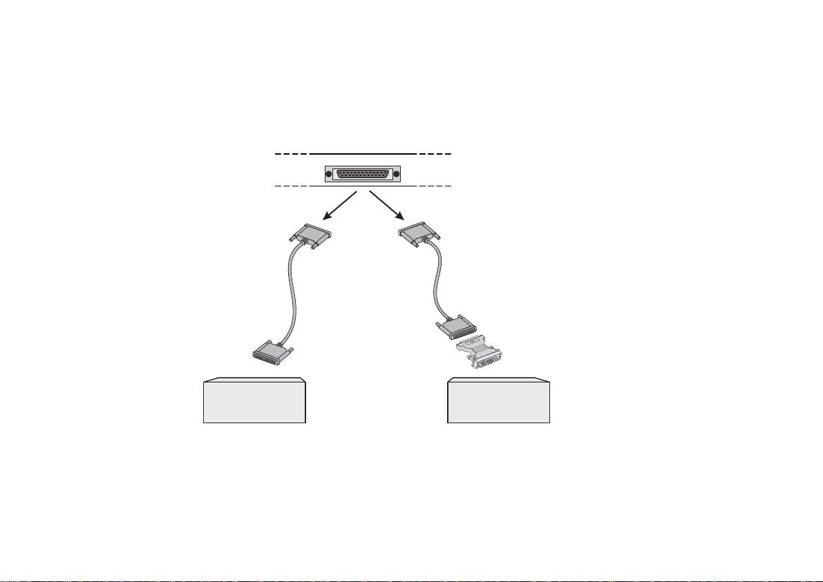
SWAN Expansion Card
The PR4000 is often sold with a SWAN card in the expansion slot. The SWAN can be connected to a modem or
DSU/CSU as shown in Figure 2.3. Cables are not included with the product.
Back Panel of PR4000
Slot with
SWAN RSV Card
or
DB-25
Male
Straight Cable
DB-25
Male
V.35 Cable Set
DB-25 Male
DB-25
Male
RS-232 Modem
with DB-25
Interface
V.35
DB-25 Female/ M.34
Male Converter
DSU/CSU
with M.34
Interface
FIGURE 2.3 SWAN EXPANSION CARD SHOWING CABLE CONNECTIONS
Chapter 2 - What is in the Box 14
Page 15

Cyclades-PR4000
Provisioning the T1/E1 Dialup Lines
This section provides information useful when provisioning the T1 or E1 dialup trunk lines for use with the CycladesPR4000 Remote Access Server. Line provisioning parameters vary widely depending on the switch being used at
the central office and the service options offered by the carrier. In North America and Japan, a digital trunk uses
a T1 speed of 1.5Mbps. In Europe and most other countries, a digital trunk runs at E1 speeds of 2Mbps. A digital
trunk is a Time Division Multiplexed (TDM) line that carries information from several channels in digital form. In a
given country, only E1 or T1 is offered.
Signaling: ISDN-PRI (CCS) or CAS
Phone lines carry signaling information used to establish and maintain connections. In a regular phone this
information translates into dialing, ring, busy signal, dial tone, caller ID, etc. In an analog phone line, the signaling
information shares the channel used to carry voice. In a T1 or E1 trunk, the signaling information for the trunk can
be carried by a separate channel or can share the same channel used to carry data. There are three basic
signaling protocols: ISDN-PRI (T1 or E1), CAS-BR (T1), or R2D/MFR2 (E1).
Newer systems use the ISDN-PRI signaling protocol, with channels dedicated to control. With this protocol, a T1
line carries 23 phone connections and an E1 line carries 30 phone connections.
In North America, older T1 systems use CAS (Channel Associated Signaling) protocols. These protocols “steal”
some of the bandwidth from the data channels using a scheme called “bit robbing” (BR) and allow a T1 line to
carry 24 phone connections. In other countries, older E1 systems use R2D/MFR2 signaling with a dedicated
channel, leaving 30 phone connections. Lines with CAS or R2D/MFR2 signaling are sometimes referred as
“Channelized T1/E1” or “DS-1”.
ISDN-PRI provides more control over connections than the older CAS or R2Ds. Given a choice between ISDNPRI and CAS/R2D, select ISDN-PRI.
Number of Phone Lines
In most applications, the maximum number of phone lines (for the protocol used) are purchased. However, it is
also possible to request fewer lines. When using fewer lines, make sure to disable the remaining channels using
the menu CONFIG =>INTERFACE =>E1/T1 =><CHANNEL> =>ENCAPSULATION =>INACTIVATE.
Chapter 2 - What is in the Box 15
Page 16

Cyclades-PR4000
ISDN Switch Type (ISDN-PRI only)
Different switch vendors have different signaling protocol implementations. If you are in the US and are given a
choice of ISDN switch types, select National ISDN 2, which is intended to be the US standard switch type. Other
common and acceptable options are Custom AT&T 5ESS and Northern Telecom DMS-100. In Europe, Euro
ISDN (ETSI) is the standard ISDN switch type, but there are still some variations in use. Examples are TR6 in
Germany and VN6 in France. Australia, Japan and Korea each have their own standard switch type. Other
countries usually adopt the European standards.
Data/Voice Support
From the phone system standpoint, analog modem connections (V.34, V.90, K56 flex) are “voice” while “data”
refers to digital connections using ISDN-BRI or V.110. Lines with CAS signaling support only voice calls. Most
ISDN-PRI lines support both data and voice channels, but some lines are configured to support only voice or only
data. If given a choice, both voice and data support is preferable. If only one may be chosen, voice should be
chosen to support modem (V.34, V.90) clients and data should be chosen to support clients using ISDN-BRI or
V.110. The Cyclades-PR4000 supports both digital and analog calls and can terminate both at the same time in
the same trunk.
Phone Numbers, Hunting Groups, and Hunting Sequence
Each T1/E1 channel can have a different phone number or be organized into hunting groups with the same phone
number. In the second case, the client gets the first available line within the hunting group. The line allocation can
be done in a linear (the first available line gets a new call, from the first line to the last or vice-versa) or round-robin
fashion. ISPs usually group all lines into one hunting group so that all customers call the same phone number.
Breaking the trunk into more than one hunting group can be used to reserve a certain number of lines for different
classes of customers.
One-Way or Two-Way Service
A line can only receive calls (dial-in) or receive and generate calls (dial-out). An ISP usually only needs to receive
calls and one-way service is the recommended configuration unless you plan to support services that require dialout (fax servers, call back, etc.).
Chapter 2 - What is in the Box 16
Page 17

Cyclades-PR4000
Signaling Method and Dialing Method (T1 CAS-BR only)
T1 with CAS signaling may require additional parameters. For Signaling Method, the selection may be MFR1,
DTMF or no signaling. For Dialing Method, the selection may be wink-start or loop-start. The suggested choice
is wink-start.
Line Coding
This refers to the way the digital data is encoded in the line. For T1 lines, the options are usually Bipolar with 8
Zeroes Substitution (B8ZS) or Alternate Mark Inversion (AMI). B8ZS is better suited to digital transmissions, so it
should be the choice if available. For E1 lines, the options are usually High Density Bipolar of Order 3 (HDB3) and
Alternate Mark Inversion (AMI). HDB3 is the more modern of the two and better suited to digital transmissions.
Framing
This refers to how the data bits are framed in the TDM bus. For T1 lines, the possibilities are D4 Super Frame
(D4) or Extended Super Frame (ESF). ESF provides error checking and should be the choice if available. For E1
lines, the choices are usually Frame Alignment Signal with or without CRC4 (4-bit Cyclic Redundancy Check). If
given a choice, select a line with CRC4, which will provide error checking.
Termination at the Customer Premises
The Cyclades-PR4000 supports T1 on a standard 100-Ohm RJ-48C connector and E1 on a standard 120-Ohm
RJ-48C connector. In some countries, especially those using E1 lines, the termination may be provided on a
Coax G703 connector (75 Ohms). An external interface converter (balum) is necessary in this case.
Chapter 2 - What is in the Box 17
Page 18

Cyclades-PR4000
Chapter 3 Using CyROS Menus
This chapter explains CyROS menu navigation and special keys. There are four ways to interact with CyROS:
• Traditional menu interface using a console or Telnet session,
• CyROS Management Utility based on interactive HTML pages,
• Front-panel display,
• SNMP (explained in the CyROS Reference Manual).
Connection Using the Console Cable and a Computer or Terminal
The first step is to connect a computer or terminal to the router using the console cable. If using a computer,
HyperTerminal can be used in the Windows operating system or kermit in the Unix operating system. The terminal parameters should be set as follows:
• Serial Speed: 9600 bps
• Data Length: 8 bits
• Parity: None
• Stop Bits: 1 stop bit
or
• Flow Control: Hardware flow control
none
Once the console connection is correctly established, a Cyclades banner and login prompt should appear on the
terminal screen. If nothing appears, see the first section of the troubleshooting appendix for help. The second
step is to log in. The preset super-user user ID is “super” and the corresponding preset password is “surt”. The
password should be changed as soon as possible, as described in chapter 13 of the installation manual and at the
end of every example in chapter 4. The login prompt and main menu are shown in Figure 3.1.
Chapter 3 - Using CyROS Menus 18
Page 19

Cyclades-PR4000
[PR4000] login : super
[PR4000] Password : ****
Cyclades Router (Router Name) – Main Menu
1 – Config 2 – Applications 3 – Logout
4 – Debug 5 – Info 6 – Admin
Select Option ==>
FIGURE 3.1 LOGIN PROMPT AND MAIN MENU
All menus have the following elements:
• Title – In the example in Figure 3.1: “Main Menu”.
• Prompt – The text: “Select Option ==>” (this text can be changed by the super user.)
• Options –The menu options, which are selected by number.
• Router Name – The default is the name of the product. Each router can be renamed by the super user for
easier identification.
Menus can also be navigated using a short-cut method. This method must be activated first by choosing a
shortcut chraacter (“+” in the example that follows) in the CONFIG =>SYSTEM =>ROUTER DESCRIPTION menu.
Typing 4+1+1 at the main-menu prompt, for example, is equivalent to choosing option 4 in the main menu (Debug),
then choosing option 1 in the debug menu (Trace), then choosing option 1 in the trace menu (Driver Trace). In
addition to menus, some screens have questions with letter choices. In the line below, several elements may be
identified:
lmi-type((A)NSI, (G)roup of four, (N)one )[A]:
• Parameter description – The name of the parameter to be configured, in this case “lmi-type”.
• Options – Legal choices. The letter in parentheses is the letter that selects the corresponding option.
• Current value – The option in square brackets is the current value.
Chapter 3 - Using CyROS Menus 19
Page 20

Cyclades-PR4000
Pressing <Enter> without typing a new value leaves the item unchanged.
Special Keys
<Enter> or <Ctrl+M> These keys are used to end the input of a value.
<ESC> or <Ctrl+I> These keys are used to cancel a selection or return to the previous menu. In
some isolated cases, this key jumps to the next menu in a series of menus at the
same level.
<Backspace> or <Ctrl+H>These keys have the expected effect of erasing previously typed characters.
L When available, this option displays the current configuration. For example, in
the Ethernet Interface Menu, “L” displays the Ethernet configuration.
<Ctrl+L
>
This key combination works like a toggle switch to allow display of one page of
information at a time or display the entire configuration without page breaks.
<Ctrl+C
>
This key combination disables any traces activated in the Debug Menu.
On leaving a menu where a change in configuration was made, CyROS will ask whether or not the change is to be
saved:
(D)iscard, save to (F)lash, or save to (R)un configuration:
Selecting
Discard
will eliminate all changes made since the last time the question was asked. Saving to
Flash
memory makes all changes permanent. The changes are immediately effective and are saved to the configuration
vector in flash memory . In this case, the configuration is maintained even after a router reboot. Saving only to the
Run
configuration makes all changes effective immediately , but nothing is saved permanently until explicitly saved
to flash (which can be done with the option ADMIN =>WRITE CONFIGURATION=>TO FLASH).
The menus and parameter lists are represented in this manual by tables. The first column contains the menu item
or the parameter, and the second column contains its description.
This menu interface is also available via Telnet if one of the interfaces has been connected and configured. The
Chapter 3 - Using CyROS Menus 20
Page 21

Cyclades-PR4000
menu interface is the same as that described earlier in this section. Using T elnet instead of a console for the initial
Ethernet configuration is discussed in Appendix C of the Installation Manual.
The CyROS Management Utility
After one of the interfaces has been connected and configured, there is another way to interact with CyROS. Type
the IP address in the location field in an HTML browser of a PC connected locally or remotely through the configured
interface. A super-user ID and password will be requested (these are the same ID and password used with the
line-terminal interface). A clickable image of the router back panel will apear, as shown in Figure 3.2.
Cyros Management Utility
Firmware version: Cyclades-PR4000: Cyros V_1.9.0i (Mar/28/00) #2
Configuration Menu Interface (Text Mode)
Global Ras Table
End HTTP session
FIGURE 3.2 CYROS MANAGEMENT UTILITY HOME PAGE
The link
Clicking on an interface will show its current status and some additional information. The link
will show a table similar to that shown in Figure 3.3. Clicking on
Chapter 3 - Using CyROS Menus 21
Configuration Menu Interface
will present an HTML version of the CyROS Main Menu, described previously .
Global RAS Table
End HTTP Session
will terminate the connection.
Page 22

Cyclades-PR4000
Seq#
1
2
3
4
5
6
7
8
Slot #2 Port#1
Slot #2 Port#3
Slot #2 Port#6
Slot #2 Port#7
Slot #2 Port#10
Slot #2 Port#11
Slot #2 Port#15
Slot #2 Port#17
Slot #2 Port#
CyROS Management Utility
Global Remote Access Table Port Status
User Name
Arlt
Marquez
Neruda
Cervantes
Casares
Allende
Skarmeta
Rozenmacher
Start Session
Time
Apr/18 18:11
Apr/18 18:05
Apr/18 18:31
Apr/18 16:05
Apr/18 18:08
Apr/18 17:41
Apr/18 18:10
Apr/18 18:09
Elapsed Time
0:04:46
0:10:46
0:05:09
2:10:56
0:07:47
0:35:27
0:05:58
0:06:34
Connect String
Md=23 V34 28800 26400
LAPM/V42Bis
Md=12 V90 28800 42666
LAPM/V42Bis
Md=21 V34 28800 24000
LAPM/V42Bis
Md=13 V34 28800 16800
LAPM/V42Bis
Md=17 V90 24000 28000
LAPM/V42Bis
Md=19 V34 31200 33600
LAPM/V42Bis
Md=20 V34 28800 31200
LAPM/V42Bis
Md=18 V32 1440
Caller ID
1115553000
1115551268
1115554811
1115550000
1115559743
1115557553
1115551174
1115559800
FIGURE 3.3 GLOBAL RAS TABLE
Chapter 3 - Using CyROS Menus 22
Page 23

Cyclades-PR4000
Clicking on one of the links in the Global RAS Table will provide more detailed information about the connection
and the user. An example is shown in Figure 3.4. The user can be disconnected with the hangup button and the
interface can be temporarily disabled by clicking on the administrative down button.
Slot #2 Port #26 Status
Username: cas
Start Session Time: Apr/18/00 18:01:29
Elapsed Time: 0:11:01
Inactivity Timeout: None
Caller ID: 5554321
modem Id 9 V32B Initial Rate 14400/14400 Current Rate 14400/14400 LAPM/V42Bis
Number of transmitted Frames: 237670
Number of transmitted bytes: 106541777
Number of transmission errors: 2368
Number of received frames: 245235
Number of received bytes: 34399893
Number of reception errors: 96
PPP LCP state = OPENED
PPP PAP state = OPENED
PPP NCP (IPCP) state = OPENED Local IPaddr (200.200.200.200) Remote IPaddr (200.200.200.100)
Hangup Connection
Current Administrative Status is . Change it toUP
Admin. DOWN
Go Back
FIGURE 3.4 CHANNEL DETAILS
Chapter 3 - Using CyROS Menus 23
Page 24

Cyclades-PR4000
Returning to the CyROS Management Utility Home Page, clicking on a T1 or E1 port on the figure will display the
channel details. There is a toggle button in the upper-right-hand corner which toggles between name and speed.
When set to name, as shown in Figure 3.5, passing the mouse over a channel displays the username. When set
to speed, it displays the carrier and speed of the connection. The ports are color-coded with the current status.
CyROS Management Utility
E1 Line - Signalling Type [CAS BR]
Inactive Port
Hardware Error
Waiting Connection
Connecting
Port In Test
Administrative Down
Connection OK
FIGURE 3.5 CHANNEL SUMMARY WITH TOGGLE SET TO NAME
Chapter 3 - Using CyROS Menus 24
Page 25

Cyclades-PR4000
Operating the Front-Panel Display
The Cyclades logo appears on the front-panel display (shown in Figure 3.6) after a sucessful boot.
Cyclades - PR4000
LCD
Ethernet 1
10Base-T
100Base-T
RX
TX
Link
Collision
Ethernet 2
10Base-T/ 100Base-T
LAN Connection
Menu
Select
WAN Connection
Port 1
Port 2
FIGURE 3.6 FRONT-PANEL DISPLAY
There are 5 push buttons: 4 arrows and one menu selection button. Pressing the menu selection button displays
the main menu, which contains the following options:
• Modem Overview
• Interface Overview
• IP Traffic
• Syslog Messages
• System Info
• Reboot (If configured to appear using the menu item CONFIG =>SYSTEM =>HARDWARE)
• Quit
Chapter 3 - Using CyROS Menus 25
Page 26

Cyclades-PR4000
Modem Overview
The status of each connection can be displayed by modem or by interface.
Modem Order
This menu item presents a screen with one box for each modem. Each row corresponds to a Modem board.
When 64 modems are present, the screen will appear as in Figure 3.7. The box on the upper left is the first
modem, the upper right is the eight modem, and so forth for as many modems as are installed.
Modem Idle
Modem Connecting
Modem Connected
Modem Transmitting and Receiving
TR
T
Modem Transmitting
R
Modem Receiving
AD
Modem Administrative Down
ND
Modem Not Detected
NO
Modem Not Operational
RE
Modem Reserved
IN
Modem Initializing
TR
ND
T
AD
R
R
AD
NO
NONDNO
FIGURE 3.7 MODEM ORDER SCREEN
Chapter 3 - Using CyROS Menus 26
Page 27

Cyclades-PR4000
Slot/Link Order
This menu item presents a screen with one box per T1/E1 channel. Figure 3.8 shows two lines with 30 channels
each. The box on the upper left is the first channel, the upper right is the eighth channel, and so forth for as many
channels as are configured.
R
Slot/Link Not Configured
Slot/Link Idle
AD
TR
ND
NO
Modem Connecting
Modem Connected
Modem Transmitting and Receiving
TR
T
Modem Transmitting
R
Modem Receiving
FIGURE 3.8 SLOT/LINK ORDER SCREEN
Chapter 3 - Using CyROS Menus 27
Page 28

Cyclades-PR4000
Interface Overview
This screen presents the status of each E1/T1 interface and indicates which modem has been allocated to each
channel. The ordering of the channels is the same as for the previous screen
AD
AD
40
09
21
Not Configured
Not Connected
Connected (PRI)
01
39
25
AD
Admin Down
AD
01
Connected to a modem
(Number of The Modem Allocated)
FIGURE 3.9 INTERFACE OVERVIEW SCREEN
Chapter 3 - Using CyROS Menus 28
Page 29

Cyclades-PR4000
IP Traffic
After choosing the interface desired, a bar graph showing bytes per second or packets per second is displayed. It
is a snapshot of the last 10 minutes of IP traffic through the interface (TX for transmitted and RX for received), with
a refresh every minute. The arrow keys toggle the display between bytes and packets per second. Pressing
<menu select> returns to the main menu.
Syslog Messages
Selecting this menu item leads to another menu that allows changes in the display of syslog messages. Syslog
messages are administrative and debug events. The following options are available:
• Display - Exibits the last syslog message generated by CyROS. Arrow keys may be used to see the syslog
history.
• Stop - New syslog messages are discarded. The syslog history remains unchanged.
• Start - New syslog messages are stored in the syslog history and are displayed.
• Clear - Clears the syslog history.
• Quit - Returns to the main menu.
System Info
This menu item presents a sequence of four screens: Hardware Information, Board Information, Modem Information,
and Boot Information. Any arrow key switches between screens. The menu select key returns to the main menu.
Chapter 3 - Using CyROS Menus 29
Page 30

Cyclades-PR4000
CHAPTER 4 STEP-BY-STEP INSTRUCTIONS FOR COMMON APPLICATIONS
This chapter provides detailed examples that can be used as models for similar applications. Turn to the example
that is closest to your application, read the explanations, and fill in the blank spaces with parameters appropriate
to your system. At the end of the section, you should have listed all the parameters needed to configure the
router. At that point, read chapter 3 if you have not already, and configure your router with help from later chapters
of the Installation Guide, when needed.
Please read the entire example and follow the instructions before turning the router on. The router is
programmed to log the super user off after 10 minutes of inactivity. All data not explicitly saved to
memory is then lost. Collecting the data
configuring the router will likely cause delays and
while
frustration.
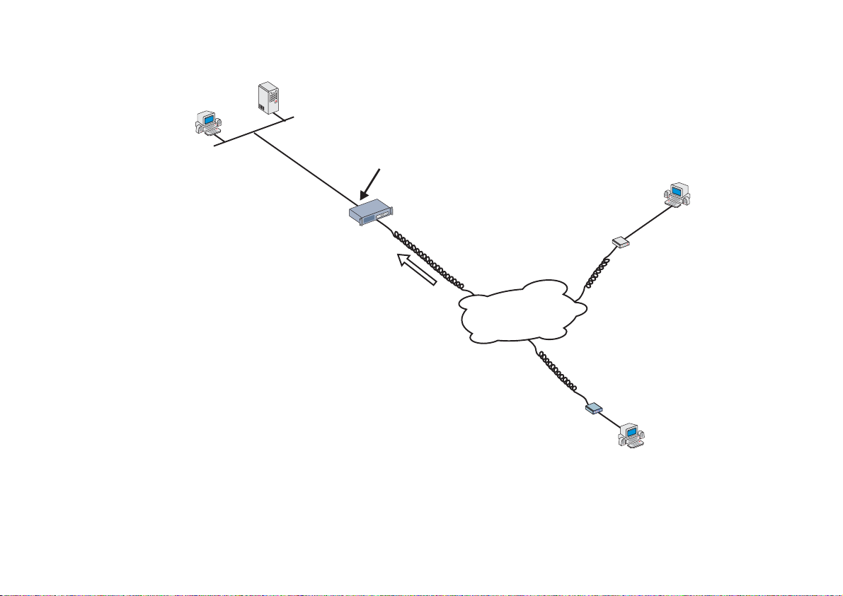
Example 1 Using the PR4000 as a Remote Access Server
This example explains the configuration of an E1 or T1 line with signaling, the most common option when the
PR4000 is used as a RAS. When the incoming call is made by a computer using a modem, the internal digital
modems are used to convert analog signals to digital signals. Either CAS or CCS signaling can be used in this
case. When the incoming call is made by an ISDN-BRI line subscriber (and the E1/T1 line is configured for CCS),
the digital modems are bypassed.
This section will guide you through a complete RAS configuration. Figure 4.1 shows the example system used in
this section. Spaces have been provided next to the parameters needed for the configuration so you can fill in the
parameters for your system. Do this now before continuing.
Chapter 4 - Step-By-Step Instructions for Common Applications 30
Page 31
Cyclades-PR4000
LAN
Radius
Server
IP Address: 100.130.130.200
PC
Network: 100.130.130.0
__________
Mask: 255.255.255.0
_________
IP Addresses: 100.130.130.11
FIGURE 4.1 RAS EXAMPLE SHOWING DIAL-IN USERS
__________
Key: Pinocchio
_______
IP Address: 100.130.130.1
PR4000
Multiple Calls
_________
100.130.130.12 …
__________
Telephone Number:
5533-3333_______
T1/E1
Telephone/ISDN
Network
Modem
PC
Network
Terminator
ISDN-BRI
Line
Remote
IP Address
Assigned on
Connection
PC
Chapter 4 - Step-By-Step Instructions for Common Applications 31
Page 32

Cyclades-PR4000
STEP ONE
The first step is to determine the parameters needed to configure the Fast Ethernet interface (ETH0). The parameters
in the Network Protocol Menu (IP) are shown in Figure 4.2. Fill in the blanks for your application in the right-most
column. These parameters will be entered into the PR4000 later, after all parameters have been determined.
Each parameter in this menu is explained in more detail in chapter 5 of the Installation Guide.
CONFIG=>INTERFACE=>FAST ETHERNET=>NETWORK PROTOCOL=>IP
Menu
Parameter Example Your Application
Active or Inactive Active enables IP communication (IPX and Transparent
Bridge are not used in this example).
Interface Unnumbered Numbered
Primary IP Address 100.130.130.1
Subnet Mask 255.255.255.0
Secondary IP Address 0.0.0.0 for none.
Enable Dynamic Local
No
IP Address
IP MTU Use the preset value, 1500. This determines whether
or not a given IP datagram is fragmented.
NAT Global, because NAT is not being used in this example.
ICMP Port Inactive
Incoming Rule List None, filters and traffic control are not included in this
example.
Outgoing Rule List
Name
None, filters and traffic control are not included in this
example.
Proxy ARP Inactive
IP Bridge Inactive
FIGURE 4.2 ETHERNET NETWORK PROTOCOL MENU PARAMETERS
STEP TWO
No more parameters are necessary for the Ethernet interface. The next step is the configuration of the E1 or T1
Chapter 4 - Step-By-Step Instructions for Common Applications 32
Page 33

Cyclades-PR4000
line using the controller. Both CAS and CCS signaling are explained. Which one is used will depend on the
services offered by the telephone system.
CONFIG=>CONTROLLER=>T1/E1
Menu
Parameter Example Your Application
Frame Mode This value is provided by the T1/E1 line provider.
For T1,
and
D4
common) and
Line Code This value is provided by the T1/E1 line provider. For T1,
B8ZS
(Alternate Mark Inversion) are used. For E1, the
AMI
choices are
Signaling Mode
Clock Mo de ( C A S o nly) Slave
Line Build Out Applies only to T1. The T1 service provider should supply
Receiver Sensitivity Short Haul
Compan ding Mode This value is provided by the T1/E1 line provider.
for ISDN-PRI (digital or analog remote access).
CCS
for analog, modem-based remote access (usually
CAS
used with telephone networks that do not support ISDN).
this parameter.
A-law
used for T1 lines.
Signaling Type
(CAS only)
Tone Signaling CAS Only. This value is provided by the T1/E1 line
Country Signaling Type ? to the options available for each country. This
Wink Start or Loop Start for T1 and R2 Digital ITU-T for
E1 are the options
provider. DTMF is the most common for T1 and MFR2
Compelled is the most common for E1.
value is provided by the T1/E1 line provider.
(Extended Super Frame, the most common)
ESF
are the options. For E1,
Non-CRC4
(Bipolar 8 Zero Substitution, the most common) and
(High-Density Bipolar) and
HDB3
is usually used for E1 lines and
are the options.
CRC4
(the most
is usually
u-law
AMI
.
FIGURE 4.3 E1/T1 CONTROLLER MENU PARAMETERS
Chapter 4 - Step-By-Step Instructions for Common Applications 33
Page 34

Cyclades-PR4000
STEP THREE
It is likely that not just anyone should have access to your LAN. A Radius or Tacacs server can be used to
authenticate the username and password of the incoming connection request. A Radius server is used in this
example. More than one Radius server can be configured. Fill in the data for your Radius Server in the table
below.
Menu CONFIG=>SECURITY=>RADIUS=>RADIUS STATUS=>ADD
Parameter Example Your Application
Radius Server IP Address 100.130.130.200
Radius Server Type
Authentication and Accounting.
Both
Radius Server Retries 5
Radius Server Timeout 5
Radius Server Encryption
pinocchio
Key
Radius Server
1812. Older standards used 1645.
Authentication Port
Radius Server Send Start
Yes
accounting
FIGURE 4.4 RADIUS SERVER PARAMETERS
Chapter 4 - Step-By-Step Instructions for Common Applications 34
Page 35

Cyclades-PR4000
STEP FOUR
The RAS Wizard can be used to set up a PPP Remote Access Server using modems or DSU/CSUs and dial-up
lines. The wizard can be used for one port or a range of ports. If the Wizard is used for a range or all ports, the
ports will be numbered consecutively.
Menu CONFIG=>INTERFACE=>T1/E1(ISDN-PRI)=><CHANNEL>=>WIZARDS=>RAS PROFILE
Parameter Example Your Application
Remote IP Address 100.130.130.11
Phone Number (CAS Only) This number is only used for callback (in the
outgoing connection request).
Digital Modem Profile ID
1
(CAS Only)
FIGURE 4.5 RAS WIZARD PARAMETERS
STEP FIVE
Now that the parameters have been defined, enter into each menu described above, in the order presented (read
chapter 3, Using Menus, if you have not done so already). Set the parameters in each menu according to the
values you wrote in the figures above. Save the configuration to flash memory at each step when requested —
configurations saved in run memory are erased when the router is turned off. If you saved part of the configuration
to run memory for some reason, save to flash memory now using the menu option ADMIN =>WRITE
CONFIGURATION =>TO FLASH. Be sure to change the superuser password using the menu option CONFIG
=>SECURITY =>USERS =>MODIFY. The user ID, super, can remain the same, but the password must be
changed to avoid unauthorized access.
If the Radius Server does not appear to be working, try switching the UDP port setting. This often resolves Radius
problems. The menu item INFO =>AUTH. SERVERS STATUS =>RADIUS SERVERS STATUS also provides
information about the status of the Radius Server. Any status other than OK means that either the RAS configuration
is incorrect or the Radius Server configuration is incorrect. It may be necessary to reboot the router after performing
the configuration described in step three, for the changes to take effect.
Chapter 4 - Step-By-Step Instructions for Common Applications 35
Page 36

Cyclades-PR4000
At this point, you should create a back-up of the configuration file (in binary) and print out a listing of the configuration.
Instructions for creating a back-up of the configuration file:
Use the menu option ADMIN =>WRITE CONFIGURATION =>TO FTP SERVER. Fill in the IP address of the
computer where the configuration file should be saved, the file name, the directory name, and the user account
information. This configuration file can later be downloaded with the ADMIN =>LOAD CONFIGURA TION =>FTP
SERVER option.
Instructions for listing the configuration:
The menu option INFO =>SHOW CONFIGURA TION =>ALL will list to the terminal screen the configuration of the
router. This can be saved as a text file and/or printed on a printer.
Chapter 4 - Step-By-Step Instructions for Common Applications 36
Page 37

Cyclades-PR4000
Example 2 Connection to an Internet Access Provider via Modem
This section will guide you through a complete router installation for the connection of a LAN to an Internet access
provider via PPP. The configuration of NAT (Network Address T ranslation) will also be shown. Figure 4.6 shows
the example system used in this section. Spaces have been provided next to the parameters needed for the
configuration where you can fill in the parameters for your system. Do this now before continuing.
RS-232___
DSU/CSU
PC
Network
192.168.0.0
Host
PR4000
IP Address
Assigned
Dynamically
Host
192.168.0.11
192.168.0.10 _________
192.168.0.1_________
192.168.0.30_________
FIGURE 4.6 CONNECTION TO ACCESS PROVIDER USING A SWAN INTERFACE AND A MODEM
Please read the entire example and follow the instructions before turning the router on. The router is
programmed to log the super user off after 10 minutes of inactivity. All data not explicitly saved to
memory is then lost. Collecting the data
while
configuring the router will likely cause delays and
frustration.
37Chapter 4 - Step-by-Step Instructions
Page 38

Cyclades-PR4000
STEP ONE
The first step is to determine the parameters needed to configure the Ethernet interface (ETH0). The parameters
in the Network Protocol Menu (IP) are shown in Figure 4.7. Fill in the blanks for your application in the right-most
column. These parameters will be entered into the router later, after all parameters have been chosen. Each
parameter in this menu is explained in more detail in chapter 5 of the Installation Guide.
CONFIG=>INTERFACE=>ETHERNET=>NETWORK PROTOCOL=>IP
Menu
Parameter Example Your Application
Active or Inactive Active enables IP communication (IPX
and Transparent Bridge are not used in
this example).
Interface Numbered
Numbered
/Unnumbered
Primary IP Address 192.168.0.1
Subnet Mask 255.255.255.0
Secondary IP
0.0.0.0 for none
Address
IP MTU Use the preset value, 1500. This
determines whether or not a given IP
datagram is fragmented.
NAT Local
ICMP Port Inactive
Incoming Rule List None, filters and traffic control are not
included in this example.
Outgoing Rule List
Name
None, filters and traffic control are not
included in this example.
Proxy ARP Inactive
IP Bridge Inactive
FIGURE 4.7 ETHERNET NETWORK PROTOCOL MENU PARAMETERS
38Chapter 4 - Step-by-Step Instructions
Page 39

Cyclades-PR4000
STEP TWO
No more parameters are necessary for the Ethernet interface. The other interface to be configured is the SWAN
in slot 1. The SWAN physical media parameters are shown in Figure 4.8. Fill in the values for your application.
The SWAN configuration is described in more detail in chapter 6 of the Installation Guide.
CONFIG=>INTERFACE=>SWAN=>PHYSICAL
Menu
Parameter Example Your Application
Mode Asynchronous
Speed 115.2k
FIGURE 4.8 SWAN PHYSICAL MENU PARAMETERS
STEP THREE
The network protocol parameters, shown in Figure 4.9, are similar to those for the Ethernet interface. Fill in the
parameters for your network in the right-most column. For an example using NAT where the Primary IP Address
is not dynamically assigned, see the chapter dedicated to NAT in the Installation Manual.
CONFIG=>INTERFACE=>SWAN=>NETWORK PROTOCOL=>IP
Menu
Parameter Example Your Application
Active or Inactive Active enables IP communication (IPX
and Transparent Bridge are not used in
this example).
Interface
Numbered
Unnumbered/
Numbered
Primary IP Address 0.0.0.0 (This number will be assigned
by the Access Provider dynamically.)
Subnet Mask 255.0.0.0
FIGURE 4.9 SWAN NETWORK PROTOCOL (IP) MENU PARAMETERS
39Chapter 4 - Step-by-Step Instructions
Page 40

Cyclades-PR4000
Parameter Example Your Application
Secondary IP
0.0.0.0 for none
Address
Enable Dynamic
Local IP Address
Yes, because the IP address of the
SWAN interface will be assigned
dynamically.
Remote IP Address
Any
Type
Remote IP Address 0.0.0.0
IP MTU Use the preset value, 1500. This
determines whether or not a given IP
datagram is fragmented.
NAT
Global Assigned
because the IP
address of the SWAN interface will be
assigned dynamically.
ICMP Port Inactive
Incoming Rule List None, filters and traffic control are not
included in this example.
Outgoing Rule List
Name
Routing of Broadcast
None, filters and traffic control are not
included in this example.
Inactive
Messages
FIGURE 4.9 CONTINUED -- SWAN NETWORK PROTOCOL (IP) MENU PARAMETERS
40Chapter 4 - Step-by-Step Instructions
Page 41

Cyclades-PR4000
STEP FOUR
The Encapsulation parameters for PPP are less straight-forward. Many of them are based on decisions that
cannot be shown in a diagram. Fortunately , the choices made here will mostly af fect the performance of the link,
rather than whether it works or not. Fill in the parameters appropriate for your system, consulting chapter 1 1 of the
Installation Guide for more information if necessary.
CONFIG=>INTERFACE=>SWAN=>ENCAPSULATION=>PPP
Menu
Parameter Example Your Application
MLPPP
PPP Inactivity
Timeout
Enable Van Jacobson
No
None
so that the connection is never
broken.
No
IP Header
Compression
Disable LCP Echo
No
Requests
Edit ACCM No Value. This will depend on the
modem used.
Time Interval to Send
Use the preset value, one.
Config Requests
Enable Predictor
No
Compression
FIGURE 4.10 PPP ENCAPSULATION MENU PARAMETERS
41Chapter 4 - Step-by-Step Instructions
Page 42

Cyclades-PR4000
STEP FIVE
A static route must be added to tell the router that all traffic not intended for the local LAN should be sent to the
Access Provider. Chapter 12 of the Installation Guide explains static routes and other routing methods available
in CyROS. Fill in the spaces in Figure 4.11 with the values for your application.
CONFIG=>STATIC ROUTES=>IP=>ADD ROUTE
Menu
Parameter Example Your Application
Destination IP
Type in the word "DEFAULT".
Address
Gateway or
Interface
Interface
Is This a Backup
Interface
, because the IP addresses
are not known at configuration time.
Link 1
in the example.
No
Route?
OSPF Advertises
No
This Static Route
FIGURE 4.11 STATIC ROUTE MENU PARAMETERS
STEP SIX
NAT must now be activated. There are two varieties of NAT: Normal and Expanded. This example uses the
Normal NAT Mode. The other mode is explained in the chapter on NAT in the Installation Manual.
Menu CONFIG =>SECURITY =>NAT =>GENERAL
Parameter Example Your Application
Nat Status Enabled
Nat Mode Normal
Disable Port Translation No
FIGURE 4.12 GENERAL NAT PARAMETERS
42Chapter 4 - Step-by-Step Instructions
Page 43

Cyclades-PR4000
STEP SEVEN
NAT parameters will now be determined for routing outside of the local LAN. Network Address Translation maps
the local IP addresses, registered in the local address range menu below, to the one global IP address assigned
by the access provider. Local IP addresses not indicated in this menu will not be translated.
Menu CONFIG =>SECURITY =>NAT =>LOCAL ADDRESS =>ADD RANGE
Parameter Example Your Application
First IP Address of
192.168.0.10
New Range
Number of IP
21
Addresses in the
Range
FIGURE 4.13 NAT LOCAL ADDRESS RANGE MENU PARAMETERS
The factory preset values for all other NAT parameters are appropriate for this example.
STEP EIGHT
Now that the parameters have been defined, enter into each menu described above, in the order presented (read
chapter 3, Using Menus, if you have not done so already). Set the parameters in each menu according to the
values you wrote in the figures above. Save the configuration to flash memory at each step when requested —
configurations saved in run memory are erased when the router is turned off. If you saved part of the configuration
to run memory for some reason, save to flash memory now using the menu option ADMIN =>WRITE
CONFIGURATION =>TO FLASH.
STEP NINE
The Ethernet interface can be tested as described in the troubleshooting appendix. The SWAN interface can be
tested in a similar manner. At this point, you should create a back-up of the configuration file (in binary) and print
out a listing of the configuration.
43Chapter 4 - Step-by-Step Instructions
Page 44

Cyclades-PR4000
Instructions for creating a back-up of the configuration file.
Use the menu option ADMIN =>WRITE CONFIGURATION =>TO FTP SERVER. Fill in the IP address of the
computer where the configuration file should be saved, the file name, the directory name, and the user account
information. This configuration file can later be downloaded with the ADMIN =>LOAD CONFIGURA TION =>FTP
SERVER option.
Instructions for listing the configuration.
The menu option INFO =>SHOW CONFIGURA TION =>ALL will list to the terminal screen the configuration of the
router. This can be saved as a text file and/or printed on a printer.
44Chapter 4 - Step-by-Step Instructions
Page 45

Cyclades-PR4000
CHAPTER 5 CONFIGURATION OF THE ETHERNET INTERFACE
The PR4000 has one Ethernet 10/100Base-T interface, provided in a standard RJ-45 modular jack, which should
be connected to an Ethernet hub or switch. Use a standard 10/100Base-T straight-through cable (not included).
When the Ethernet link is correctly connected, the link LED will be lit. The menus for the Ethernet Interface are
independent of the speed of the link.
If your network uses 10Base2 (thin coaxial cable) or 10Base5 (thick coaxial cable), you will need a transceiver to
convert between the different Ethernet media. A crossover cable is required for direct connection to a computer
(an RJ-45 Ethernet pinout is provided in appendix B). Note: While Cyclades Power Routers work with most
standard RJ-45 cable/connectors, shielded Ethernet cables should be used to avoid interference with other
equipment .
The parameters in the encapsulation menu are preset at the factory and it is usually not necessary to change
them. The first step in the Ethernet configuration is to choose which network protocol to use and assign values to
the relevant parameters. Either IP, Transparent Bridge, or IPX (optional) must be activated. In this chapter, IP
Bridges are also described. Use the information provided below to set the parameters for the Ethernet interface.
The IP Network Protocol
Some parameters are explained in detail in later chapters. At this point, the preset values provided by the
operating system can be accepted and the interface will work at a basic level.
Network Protocol Menu CONFIG =>INTERFACE =>ETHERNET =>NETWORK PROTOCOL =>IP
Parameter Description
Active or Inactive Activates this interface.
Interface
Unnumbered interfaces are used for point-to-point connections.
Unnumbered
Assign IP From
Interface
Primary IP Address Applies to
Subnet Mask Applies to
Applies to
to this one.
Unnumbered
Numbered
Numbered
interfaces. Address assigned to this interface.
interfaces. Subnet mask of the network.
interfaces. Applies the IP address of another router interface
This table is continued.
Chapter 5 - Configuration of the Ethernet Interface 45
Page 46

Cyclades-PR4000
Network Protocol Menu (Continued)
Parameter Description
Secondary IP
Address
Applies to
Numbered
interfaces. Indicates a second (or third, etc. up to eight) IP
address that can be used to refer to this interface. This parameter and the next are
repeated until no value is entered.
Subnet Mask Applies to
Numbered
interfaces. Subnet mask of
Secondary IP Address
.
IP MTU Assigns the size of the Maximum Transmission Unit for the interface. This determines
whether or not a given IP datagram is fragmented.
NAT Determines the type of IP address if NAT is being used. Use
otherwise. See
Global
chapter 13 or the examples in chapter 2 for details on how to configure NAT.
ICMP Port
causes the router to send ICMP Port Unreachable messages when it receives
Active
UDP or TCP messages for ports that are not recognized. This type of message is
used by some traceroute applications, and if disabled, the router might not be identified
in the traceroute output. However, there are security and performance reasons to
leave this option
Inactive
.
Incoming Rule List Filter rule list for incoming packets. See chapter 14 for instructions on how this
parameter should be set.
Detailed Incomi ng IP
Accounting
Applies when a list is selected i n the pre vious parameter. See explanation of IP
Accounting in chapter 12. IP Accounting for a rule requires that the parameter
CONFIG =>RULES LIST=>IP=>CONFIGURE RULES=>ADD RULE=>ALLOW
Yes
.
Detailed
Outgoing Rule List
Name
Detailed Outgoing IP
Accounting
Routin g o f Broadcas t
Messages
ACCOUNT PROCESS also be
Filter rule list for outgoing packets. See chapter 14 for instructions on how this
parameter should be set.
Applies when a list is selected i n the pre vious parameter. See explanation of
Incoming IP Accounting
.
Activating this parameter causes the router to route broadcast messages from the LAN
to the WAN and vice-versa. An individual interface can be excluded by setting this
parameter to
Inactive
, without effecting the broadcast of messages on the other
interfaces.
Proxy ARP Causes the router to answer ARP requests with its own MAC address for IP addresses
reachable on another interface.
Chapter 5 - Configuration of the Ethernet Interface 46
Page 47

Cyclades-PR4000
IP Bridge
An IP Bridge is used to divide a network without subnetting. Whenever a subnetwork is created, two IP numbers
are lost — one describing the network and the other reserved for broadcast. This does not occur with an IP
Bridge.
200.240.240.9
200.240.240.3
200.240.240.2
200.240.240.1
ETH0
PR4000
Link 1
PR3000
..................................
ETH0
200.240.240.8
200.240.240.4
FIGURE 5.1 IP BRIDGE EXAMPLE
Chapter 5 - Configuration of the Ethernet Interface 47
Page 48

Cyclades-PR4000
In Figure 5.1, an example of the use of an IP Bridge is given. From the available IP addresses, the range
200.240.240.4 to 200.240.240.8 is bridged to another physical location. The following parameters apply only for
IP Bridge.
Network Protocol Menu (Continued) -- (IP Bridge)
Parameter Description
IP Bridge Activates the IP Bridge functionality.
The following parameters apply only if IP Bridge is
Initial IP Address to
be Bridged
Indicates the start of the range of IP addresses to be transferred to another physical
location. This and the next three parameters are repeated in case the bridge is to be
Active
.
broken up into various sections. Up to 8 sections can be defined. In the example, this
value is 200.240.240.4.
Ending IP Address to
be Bridged
Broadcast Over the
Indicates the end of the range of IP addresses to be transferred to another physical
location. In the example, this value is 200.240.240.8.
Allows propagation of broadcast IP packets over this bridge.
Link
Bridge Over Link Indicates which link forms the other half of the bridge. In the example, link 1 is used.
Other Parameters
Transparent Bridge is covered in chapter 7 and IPX is covered in chapter 15. The parameters defined in the
Routing Protocol and Traffic Control Menus should be set after reading chapters 11 and 14, respectively. It is
probably best to complete the basic configuration of all router interfaces, then return to the routing protocol and
traffic control menus after general routing and traffic control strategies have been defined.
Chapter 5 - Configuration of the Ethernet Interface 48
Page 49

Cyclades-PR4000
CHAPTER 6 THE SWAN INTERFACE
This chapter describes how to configure a SWAN interface. The physical link should be set up as shown in
chapter 2, according to the type of modem or device at the other end of the connection and the type of SWAN port.
STEP ONE
The first step in the SWAN interface configuration is to define its physical characteristics. These parameters are
presented in the Physical Menu Table.
Physical Menu CONFIG=>INTERFACE=>SWAN=>PHYSICAL
Parameter Description
Mode Asynchronous or Synchronous. This parameter is determined by the mode of the
device at the other end of the connection.
Clock Source Applies for
Synchronous Mo de
. Whether this interface provides clock for the device at
the other end of the cable or vice-versa. When the interface is connected to a modem,
the
Clock Source
Receive Clock Applies for
compare incoming messages with the clock it is generating (
it receives from the sender along with the message (
is always
External
Internal Clock Source
.
. When this interface provides clock, it can either
) or with th e cl ock
Externa
l is
External
Internal
).
recommended.
Speed Applies for
Internal Clock Source
. Determines at which speed the data will be sent
across the line.
Media for SWAN
Cable
Type of cable -- RS-232, V.35 or X.21. Usually the type is cable is d etected by the
router.
Chapter 6 - Configuration of the SWAN Interface 49
Page 50

Cyclades-PR4000
STEP TWO
The second step is to choose a data-link protocol in the Encapsulation menu. There are many encapsulation
options on this interface.
For synchronous communication:
• Frame Relay: the Frame Relay Protocol is based on frame switching and constructs a permanent virtual
circuit (PVC) between two or more points.
• X.25: The X.25 Protocol is generally used to connect to a public network. The router can act either as a DTE
or a DCE.
• HDLC: A proprietary alternative to PPP.
For synchronous or asynchronous communication:
• PPP: The PPP (Point-to-Point) protocol is used for leased, dial-up, and ISDN lines. Multilink PPP is also
provided.
Information on how to determine the values of the parameters for each data-link protocol is provided in chapter 8.
STEP THREE
The third step is to set the Network Protocol parameters. Information for this step is provided in chapter 7.
Chapter 6 - Configuration of the SWAN Interface 50
Page 51

Cyclades-PR4000
STEP FOUR
If PPP Encapsulation is being used, a type of authentication should be chosen. This is done in the authentication
menu.
Authentication Menu CONFIG=>INTERFACE=>SWAN=>AUTHENTICATION
Parameter Description
Authentication Type
uses the list of users defined in CONFIG=> SECURITY=>USERS=>ADD.
Local
uses either Radius or Tacacs to authenticate the user.
Server
Remote
is when this interface is considered to be the user and the
other
end of the
connection performs the authentication
Username Applies when Authentication Type is Remote. The username the remote device
expects to receive.
Password Applies when Authentication Type is Remote. The password the remote device
expects to receive.
Authentication Server Applies when
Authentication Type
is
. Indicates that either a Radius or Tacacs
Server
server is used for validation. The location and othe r parameters of the server must be
configured in C ONFIG=> SECURITY. See section 4.3 of the CyROS Reference
Guide.
Authentication
Protocol
Applies when
Authentication Type
be used for authentication.
is
Local
or
. Either PAP or CHAP or both can
Server
STEP FIVE
The parameters defined in the Routing Protocol and Traffic Control Menus should be set after reading chapters 9
and 12, respectively . It is probably best to complete the basic configuration of all router interfaces, then return to
the routing protocol and traffic control menus after general routing and traffic control strategies have been defined.
Chapter 6 - Configuration of the SWAN Interface 51
Page 52

Cyclades-PR4000
CHAPTER 7 THE E1 AND T1 INTERFACES, WITHOUT SIGNALING
The menus relating to configuration of the E1 and T1 interfaces without signaling are given in this chapter. T1 is
a standard used in the United States, Canada, and Japan. It has a clock speed of 1.5MHz and has 24 channels
of 64K each. One of the channels is reserved for signaling when ISDN/PRI is used. E1 is a standard used in
Europe and many other countries. It has a clock speed of 2MHz and has 32 channels with two reserved for
signaling. Aside from this, there are few differences between the two standards in terms of configuration.
The Controller menu tree for the PR4000 (for Signaling Mode = None) is shown in figure 7.1
Config
Controller
T1/E1
Frame Mode
Line Code
Signaling Mode
Clock Mode
Line Build Out
Receiver Sensitivity
Companding Mode
Add Group
Timeslot
Timeslot Allocation
Timeslot Start
Timeslot End
Timeslot N
Delete Group
Edit Group
Channel Group Number
Channel Group Number
Rest Same as Add Group
Clear All Groups
FIGURE 7.1 PR4000 CONTROLLER MENU TREE
Chapter 7 - The E1 and T1 Interfaces, Without Signaling 52
Page 53

Cyclades-PR4000
The controller parameters are explained in the table that follows.
Controller Menu CONFIG=>CONTROLLER=>T1/E1
Parameter Description
:
Frame Mode
Line Code
Signaling Mode Only appear s f or t h e P R4000.
Clock Mode Selects the clock mode:
Line Build Out Applies only to T1. Sets the attenuation on the TX line. The T1 service provider
Receiver Sensitivity
T1
E1
T1
Inversion). E1:
otherwise, see chapter 8.
should supply this parameter.
Short haul
data, usually when the router is installed more than 2000 feet from the cable
termination.
(Extended Super Frame, the most common) and D4 are the op tions.
ESF
:
:
(the most common) and
CRC4
(Bipolar 8 Zero Substitution, the most com mon) and
B8ZS
(High-Density Bipolar) and
HDB3
Master
is usually used.
Long haul
Non-CRC4
for channelized lines without signaling,
None
or
Slave
is necessary if attenuation prevents reception of
are the op tions.
.
AMI
AMI
.
(Alternate Mark
For the CCS Signaling Mode (ISDN-PRI) and the CAS Signaling Mode, read chapter 8
this chapter.
INSTEAD
of
The T1/E1 interface can be broken up into channels, defined by timeslots. Each timeslot is a slice of time allotted
to throughput from a particular source. The configuration can be done in three ways:
1 Full T1/E1: Only one channel group is defined and no others are allowed. All timeslots are allocated
automatically to this channel.
2 Fractional T1/E1: Only one channel group is defined. One or more timeslots are allocated to this channel.
The number of timeslots can be increased at a later time.
3 Channelized T1/E1: Many channels are defined, with one or more timeslots allocated to each channel.
Chapter 7 - The E1 and T1 Interfaces, Without Signaling 53
Page 54

Cyclades-PR4000
STEP ONE
The first step in the T1/E1 configuration is the assigning of channel groups, performed in the channel groups
menu shown in Figure 8.1. A brief description of the add group menu parameters is given in the table.
Add Channel Group Menu CONFIG =>CONTROLLER =>T1/E1 =>CHANNEL GROUPS =>ADD GROUP
Parameter Description
Timeslot
is used for Full T1/E1 as described above.
Full
Fractional
is for Fractional or
Channel ized T1/E1 as desc ribed abov e .
Timeslot Allocation
Contiguous
allows configuration of a range of timeslots while
Manual
presents each
available timeslot one by one.
Timeslot Start Applies for
Timeslot End Applies for
Timeslot N Applies for
Contiguous Timeslot Allocation
Contiguous Timeslot Allocation
Manual Timeslot Allocation
. Defines the beginning of the range.
. Defines the end of the range.
. Allows inclusion of this timeslot in the channel.
STEP TWO
The parameters for each E1/T1 channel are configured in the CONFIG =>INTERFACE =>T1/E1 =>
<CHANNEL>
menu. A summary menu tree is given in Figure 7.2.
A brief description of each principal item appears in the following table.
E1/T1 Interface Menu CONFIG=>INTERFACE=>T1/E1=>
<CHANNEL>
Menu Item Descri pt i o n
Encapsulation Determines the data-link layer protocol to be used for this communication link.
Network Protocol Provides menus for the IP and Transparent Bridge parameters, including rules to be
applied to this interface.
Routing Protocol Submenus for RIP and OSPF configuration.
Traffic Control Sets the bandwidth of the connection for use with traffic control rules and associates a
traffic control rule list to this interface. See chapter 14 for more information on traffic
control rules.
Authentication Determines the method used for authentication for connections on this line.
Chapter 7 - The E1 and T1 Interfaces, Without Signaling 54
Page 55

Cyclades-PR4000
Config
Interface
T1/E1
Channel
Encapsulation
(if Channelized)
Network Protocol [menu shown in a later figure]
Routing Protocol [menu shown in a later figure]
Traffic Control
Authentication
FIGURE 7.2 E1/T1 INTERFACE CONFIGURATION MENU TREE
STEP THREE
There are many encapsulation options on this interface.
For full T1/E1:
• Frame Relay,
• PPP,
• X.25, and
• HDLC.
Frame Relay [menu shown in a later figure]
PPP [menu shown in a later figure]
X.25 [menu shown in a later figure]
HDLC
Keep Alive Interval
Inactive
General
Bandwidth
IP Traffic Control List
Authentication Type
Username
Password
Authentication Server
Authentication Protocol
Chapter 7 - The E1 and T1 Interfaces, Without Signaling 55
Page 56

Cyclades-PR4000
For channelized T1/E1:
• PPP and HDLC.
The Encapsulation options are described in chapter 10.
STEP FOUR
The Network Protocol Menu parameters must be set next. A description of these parameters appears in chapter
9. The remaining menus in Figure 7.2 are described in later chapters. Routing Protocols is the subject of chapter
1 1, and Traffic Control is discussed in chapter 14. The Authentication Menu is only relevant when PPP Encapsulation
is used.
Authentication Menu CONFIG =>INTERFACE =>T1/E1 =>
<CHANNEL>
=>AUTHENTICA TION
Parameter Description
Authentication Type
uses the list of users defined in CONFIG =>SECURITY =>USERS =>ADD.
Local
uses either Radius or Tacacs to authenticate the user.
Server
Remote
is when this interface is considered to be the user and the
other
end of the
connection performs the authentication
Username Applies when Authentication Type is Remote. The username the remote device
expects to receive.
Password Applies when Authentication Type is Remote. The password the remote device
expects to receive.
Authentication Server Applies when
Auth en tication Ty p e
is
. Indicates that either a Radius or Tacacs
Server
server is used for validation. The location and other parameters of the server must be
configured in CONFIG=>SECURITY. See section 4.3 of the CyROS Reference Guide.
Authentication
Protocol
Chapter 7 - The E1 and T1 Interfaces, Without Signaling 56
Applies when
Auth en tication Ty p e
be used for authentication.
is
Local
or
. Either PAP or CHAP or both can
Server
Page 57

Cyclades-PR4000
CHAPTER 8 THE E1 AND T1 INTERFACES, WITH SIGNALING
Two varieties of signaling are available. The older mode, called CAS, and the newer mode, called CCS (which is
used for ISDN-PRI). The first step in the configuration process is to configure the channels using the Controller
menu. The Controller Menu tree is shown in Figure 8.1. The parameters are described in the table that follows.
Config
Controller
E1/T1 Frame Mode
Line Code
Signaling Mode
Clock Mode
Receiver Sensitivity
Companding Mode
Signaling Type
Tone Signaling
Contry Signaling
Switch Type
FIGURE 8.1 THE CONTROLLER MENU TREE
57Chapter 8 - The E1 and T1 Interfaces, With Signaling
Page 58

Cyclades-PR4000
Controller Menu CONFIG=>CONTROLLER=>T1/E1
Parameter Description
:
Frame Mode
Line Code
Signaling Mode
Clock Mode Selects the clock mode:
Line Build Out Applies only to T1. Sets the attenuation on the TX line. The T1 service provider should
Receiver
Sensitivity
Companding
Mode
Signaling Type Applies when
Tone Signaling Applies when
Country
Signaling
Switch Type Applies when
T1
E1
T1
Inversion). E1:
None
for anal o g , m odem-bas e d r e mote acce ss ( usually used with telephone n etwork s that do not
support ISDN).
supply this parameter.
Short haul
data, usually when the router is installed more than 2000 feet from the cable termination.
Defines the compression mode to be used. Depends on the telephone exchange and the
E1/T1 provider should supply this parameter.
is usually used for T1 lines.
by the service provider. The options are R2-Digital, ITU-T, and R2-Analog.
DTMF is the most common tone signaling for T1 and MFR2 Compelled is the most
common for E1.
Applies when
parameters.
supplied by the service provider.
(Extended Super Frame, the most common) and D4 are the op tions.
ESF
:
:
(the most common) and
CRC4
(Bipolar 8 Zero Substitution, the most common) and
B8ZS
(High-Density Bipolar) and
HDB3
for channelized lines without signaling (see chapter 7),
Master
is usually used.
Long haul
Signaling Mode
Signaling Mode
Signaling Mode
Signaling Mode
is
is
is
is
or
CAS
CAS
CAS
CCS
Non-CRC4
Slave
is necessary if attenuation prevents reception of
. Selects the signaling type. This should be supplied
. Will depend on what is expected by the line provider.
. Determines country-dependent signaling
. Selects the signaling protocol. This should be
are the op tions.
.
A-law
AMI
.
AMI
CCS
is usually used for E1 lines and
(Alternate Mark
for ISDN-PRI and
u-law
CAS
58Chapter 8 - The E1 and T1 Interfaces, With Signaling
Page 59
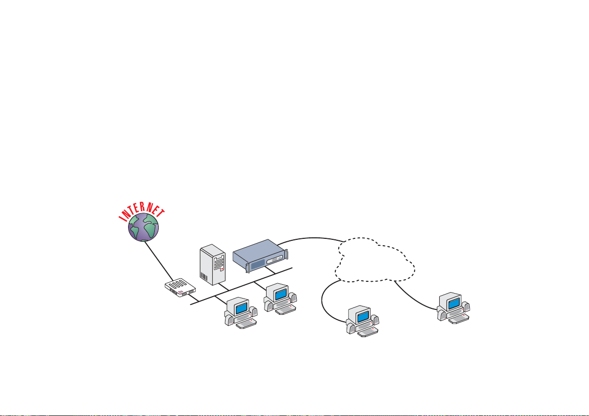
Cyclades-PR4000
The CCS Signaling Mode (ISDN-PRI)
ISDN, the Integrated Services Digital Network, was intended to be a digital upgrade to the current analog telephone
system. The ISDN discussed in this chapter is N-ISDN, where the N is for Narrow Band. A Broad Band ISDN also
exists. There are two ISDN interfaces:
• BRI — Basic Rate Interface — used for residential or small-business access.
• PRI — Primary Rate Interface — used to provide access or used by large businesses for access.
Two PRI interfaces are provided on the PR4000 via E1 or T1 ports with CCS Signaling. These connections can
be digital or analog (via a modem). The data layer protocols CHAR, PPPCHAR and Slip are used with a modem
connection.
A typical application in an Internet Service Provider is shown in Figure 8.2.
Router
Application
Server
Integrated
RAS
ISDN Line
Telephone/
ISDN Network
BRI Line
PC
PC
FIGURE 8.2 ISDN-PRI APPLICATION EXAMPLE
Analog Line
Remote Users
59Chapter 8 - The E1 and T1 Interfaces, With Signaling
Page 60

Cyclades-PR4000
After the channel groups are defined, the ISDN line and channels must be configured. The ISDN-PRI Interface
Configuration Menu tree is shown in Figure 8.3.
Config Interface
FIGURE 8.3 ISDN-PRI INTERFACE CONFIGURATION MENU TREE
T1/E1
(ISDN-PRI)
ISDN
One
Channel
Range
All Channels
Main Phone
Idle Timeout
T200
N200
T203
Add Entry
Destination IP Address
DestinationPhone #
Slot N Channel #
Delete Entry
Edit Entry
Same as Add Entry
Clear All Entries
Encapsulation
Network Protocol
Routing Protocol
ISDN
Traffic Control
Bandwidth
IP Traffic Control List
Authentication
Authenticarion Type
Username
Passaword
Authentication Server
Wizards
Authenticarion Protocol
Same Parameters as One Channel
Same Parameters as One Channel
60Chapter 8 - The E1 and T1 Interfaces, With Signaling
Page 61

Cyclades-PR4000
The general ISDN options are explained first.
ISDN General Menu CONFIG=>INTERFACE=>T1/E1(ISDN-PRI)=>ISDN
Parameter Description
Main Phone # Principal phone number assigned to the ISDN trunk line. Leave this parameter blank if this
number should not be confirmed by the router. This is recommended when the provider
does not send the trunk line number in the incoming call message.
Idle Timeout Time, in minutes, for the connection to time out if there is no traffic. For this to work, any
status messages, like PPP's LCP Echo Requests, must be disabled. The value 0 disables
the timeout function.
T200 Data-layer timer. When the router sends a command, this timer determines how long it
should wait for a response.
N200 Data-layer number of re-tries. When the T200 period passes without a response, the
command is re-sent up to N200 times.
T203 When no messages are received for T203 seconds, an enquiry (RR or RNR) is sent.
At the end of this parameter list appears the menu for the dial-out table. It can also be reached by using the
<ESC> key at any time during the parameter list.
Each entry is an association between a channel and the IP Address and Phone number at the other end of the
connection. The router uses the IP information stored here in its routing table. When a packet arrives at the
router, and the IP is listed in the dial-out table, the router will attempt a connection on the slot indicated using the
associated phone number. The parameters for each entry are given next.
Add Entry Menu CONFIG =>INTERFACE =>T1/E1(ISDN-PRI)= >ISDN =><ESC> =>ADD ENTRY
Parameter Description
Destination IP
IP Address assigned to the remote connection.
Address
Destination
Phone number assigned to the remote connection
Phone #
Slot N Channel # Channel used to reach this destination.
61Chapter 8 - The E1 and T1 Interfaces, With Signaling
Page 62
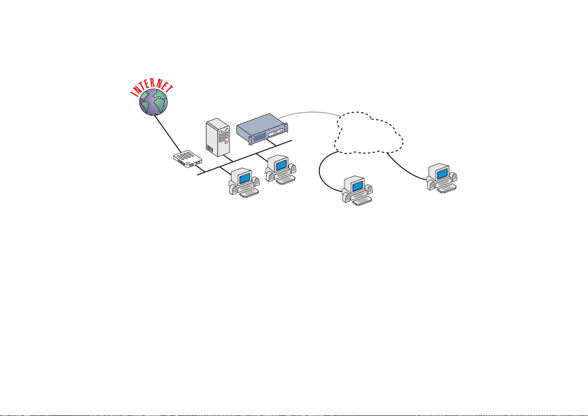
Cyclades-PR4000
The CAS Signaling Mode
A typical application that uses CAS Signaling is shown in Figure 8.4.
Application
Server
Integrated
RAS
CAS Line
Telephone
Network
Analog Line
Remote Users
Router
Analog Line
PC
PC
FIGURE 8.4 CAS APPLICATION EXAMPLE
The CAS Signaling Mode does not have a menu equivalent to the CONFIG =>INTERFACE =>T1/E1(ISDN-PRI)
=>ISDN menu described above. Both signaling modes have a mode-specific menu at the channel level, with
different names, but basically the same function. This menu, CONFIG =>INTERFACE =>T1/E1 =>
<CHANNEL>
=>SIGNALING, will be described in the next section. The Interface Configuration tree for E1/T1 with CAS Signaling
is shown in Figure 8.5
62Chapter 8 - The E1 and T1 Interfaces, With Signaling
Page 63

Cyclades-PR4000
Config
Interface
E1/T1 (CAS)
One Channel
Encapsulation
Network Protocol
Routing Protocol
Signaling
Traffic Control
Authentication
Wizards
Bandwidth
IP Traffic Control List
Authentication Type
Username
Password
Authentication Server
Authentication Protocol
Range
All Channels
Same Parameters as One Channel
Same Parameters as One Channel
FIGURE 8.5 CAS INTERFACE CONFIGURATION MENU TREE
Parameters Independent of Signaling Mode
The channel specific parameters can be set for each channel individually, for a range of channels, or for all
channels. Wizards are available to automatically configure the channels for typical applications. Details appear
at the end of this chapter. The notation
Channels
where appropriate. The following menu options are available for each channel:
<CHANNEL>
will be used to represent
One Channel, Range
, or
All
63Chapter 8 - The E1 and T1 Interfaces, With Signaling
Page 64

Cyclades-PR4000
Channel Menu CONFIG=>INTERFACE=>T1/E1=>
Menu Option Description
Encapsulation Determines the data-link layer protocol to be used for this communication link.
Network Protocol Provides menus for the IP and Transparent Bridge parameters, including rules to be applied to this
Routing Protocol Configures RIP parameters.
ISDN(CCS) / Signaling
(CAS)
Traffic Control Sets the
Authentication Determines the method used for authentication for connections on this line.
Wizards Tools that aid in the configuration of the interface for common applications.
interface.
Sets parameters particular to the signaling mode, and determines the phone number and modem
profile.
Rule List
Bandwidth
to this interface. See section 4.7 for more information on traffic control rules.
of the connection for use with traffic control rules and associates a
<CHANNEL>
Traffic Control
The encapsulation options, PPP, PPPCHAR, CHAR, Slip, and SlipChar are discussed in chapter 10.
Multilink Options
There are three ways to make two or more physical links perform as one logical link:
1 Multichassis, Multilink PPP,
2 Multilink PPP,
3 CyROS Multilink (at the network-protocol level).
Multichassis PPP is a feature that allows two or more connections to different PR4000s on the same LAN act as
one logical connection. The Cyclades Multichassis PPP implementation is compatible with the Lucent Portmaster
3 (either PR4000s/PR3000s or Portmaster 3s can be used to form the multichassis circuit). The multichassis PPP
functionality is demonstrated in Figures 8.6 and 8.7.
Figure 8.6 shows a RAS bank in an Internet Service Provider. The RAS that receives the first connection becomes
the master and the connection becomes the primary link. The information sent on link 1 passes through the RAS
and continues on to its destination (in this example, a server on the LAN). At the same time, the RAS (IP
200.200.200.1 in the example) sends a broadcast message to all other RASs in the same group letting them know
that it has the primary link for this PPP connection.
64Chapter 8 - The E1 and T1 Interfaces, With Signaling
Page 65

Cyclades-PR4000
Internet Service Provider
ISDN
Modem
Link 1
Packet
Primary Link
LAN
PR4000
Master
Server
Packet
MC PPP End Point Discriminator 11:22:33:44:55:66
MC PPP IP Address (Ethernet IP Address): 200.200.200.1
PR4000
BC
BC
MC PPP End Point Discriminator 11:22:33:44:55:66
MC PPP IP Address (Ethernet IP Address): 200.200.200.2
PR4000
BC
MC PPP End Point Discriminator 11:22:33:44:55:66
MC PPP IP Address (Ethernet IP Address): 200.200.200.3
FIGURE 8.6 FIRST INCOMING CONNECTION OF A MULTICHASSIS PPP CIRCUIT
The RAS that receives the second connection from the same ISDN modem (shown in Figure 8.7), has already
been informed by the broadcast message that the first RAS has the primary link. The connection is set up as a
secondary link with this RAS (IP 200.200.200.3 in the example) as the slave. The information is not sent directly
to its final destination. Rather, the packets are sent to the master RAS where they are joined with packets sent
through other physical links before being forwarded to their final destination.
65Chapter 8 - The E1 and T1 Interfaces, With Signaling
Page 66
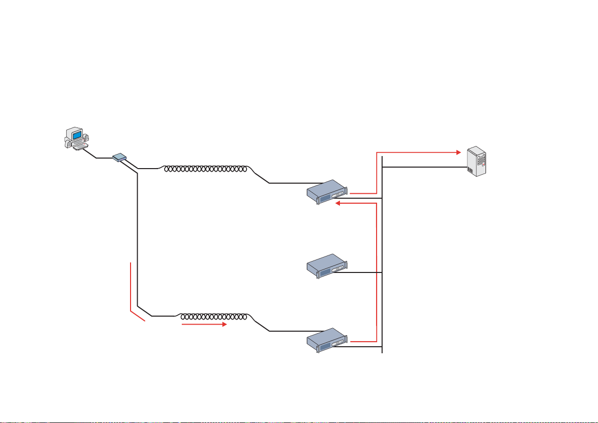
Cyclades-PR4000
The info menu items INFO=> SHOW MCPPP LINKS and INFO=> SHOW MCPPP NEIGHBORS provide information
about the PPP connections and the other RASs forming the circuit. The tool DEBUG=> MESSAGE TRACE=>
MCPPP may be useful in discovering MCPPP problems. Another tool exists which must be used in the RAS
containing the primary link for a given PPP connection. The menu option ADMIN=> KILL VIRTUAL SESSION will
show all active secondary links. Selecting one of them will cause the master RAS to send a message to the slave
RAS holding that secondary link, ordering it to drop its connection.
Internet Service Provider
ISDN
Modem
Link 2
Link 1
Primary Link
LAN
PR4000
Master
IP Address 200.200.200.1
PR4000
IP Address 200.200.200.2
Server
Packet
Secondary Link
PR4000
Packet
Slave
IP Address 200.200.200.3
FIGURE 8.7 SECOND INCOMING CONNECTION OF A MULTICHASSIS PPP CIRCUIT
66Chapter 8 - The E1 and T1 Interfaces, With Signaling
Page 67

Cyclades-PR4000
Multilink PPP (MLPPP) is similar in functionality to the Multichassis feature. The primary difference is that all
physical links reside in the same RAS/Router. It is similar to the CyROS Multilink capability described in section
4.4 of the CyROS Refrence Guide, but it is implemented at the data-link level instead of the network-protocol
level. When compared to Multilink, MLPPP is slightly more efficient and less generic (because it applies only to
PPP encapsulation).
Router A
Modem
Modem
Modem
Modem
Link 2 (Bundle 6)
Link 1
(Bundle 6)
Router B
FIGURE 8.8 MULTILINK PPP EXAMPLE
In Figure 8.8, Router B connects to Router A via two modem connections to achieve a larger bandwidth.
Router A accepts the two physical connections, but treats them as one logical connection (one “bundle”).
MLPPP must be enabled on all interfaces that will form this bundle, (and on both sides of the connection), with
the same bundle identifier specified for each.
67Chapter 8 - The E1 and T1 Interfaces, With Signaling
Page 68

Cyclades-PR4000
Configuration of Multilink PPP (with an extension to Multichassis Multilink PPP) includes the following steps:
STEP ONE
The first four parameters in the PPP Menu must be defined. The PPP Menu can be reached by following the path:
CONFIG =>INTERFACE =>
<INTERFACE or LINK>
=>ENCAPSULATION =>PPP. The first parameter enables
MLPPP. The second parameter determines the type of connection (leased line, dial-in, etc.). The third parameter
is the number assigned to the bundle, as described above (except for dial-in lines, where the bundle is defined
dynamically). The number itself is not important, but must be consistently used by the routers on both ends of the
connection. The fourth parameter determines the maximum number of links included in the multilink PPP circuit.
STEP TWO (only for Multichassis Multilink PPP)
The menu CONFIG =>IP =>MCPPP contains the only two parameters necessary to enable MCPPP. The first is
the MCPPP End Point Discriminator, which must be the same for all RASs that will participate in the Multichassis
Multilink PPP Circuit. The value of the number is immaterial, but it must have the form of a MAC number, as
shown in the example. The other parameter is the MCPPP IP Address, which must be the same as the Ethernet
IP address for the LAN where the other RASs are located. The MCPPP parameters must be set for all the RASs
that will participate in the circuit.
The Network Protocol Menu tree is explained in chapter 9. The only routing protocol available is RIP. RIP is
described in chapter 11. For each channel, certain signaling parameters must be configured. This menu tree is
shown in Figure 8.9.
Config
Interface
E1/T1 <Channel>
ISDN/
SIgnaling
Connection Type
Phone #
Increment By
Digital Modem Profile ID
Automatic Dial Out
Use DSP to Dial-Out
FIGURE 8.9 CHANNEL ISDN (OR SIGNALING) MENU TREE
68Chapter 8 - The E1 and T1 Interfaces, With Signaling
Page 69

Cyclades-PR4000
Channel ISDN Menu CONFIG=>INTERFACE=>T1/E1(ISDN-PRI)=>
<CHANNEL>
=>ISDN
or
Channel Signaling Menu CONFIG=>INTERFACE=>T1/E1(CAS)=>
<CHANNEL>
=>SIGNALING
Parameter Description
Connection Type Applies only for ISDN. Whether the line will be used to receive (dial-in) or send (dial-out)
messages, or both.
Phone # for this
Channel
Applies for Dial-in, or Both. If a specific phone number is assigned to each channel,
enter it here. Usually this does not happen.
Increm e nt By Applies on ly for CAS, when configuring a r ange or all channel s. Inc rement b y z e ro
assigns all channels in the range the same phone number (set in the previous item).
Increment by one assigns consecutive phone numbers to all channels in the selected
range.
Digital Modem
Profile ID
Automatic Dial Out Applies only for ISDN and Dial-out. If
Applies for Dial-in, or Both. The modem profiles are defined in CONFIG =>SYSTEM
=>MODEMS =>DIGITAL MODEM.
, the router will try to connect with the first
Yes
destination listed in the dial-out table as soon as the ISDN line is up and synchronized. If
, the connection will occur only on demand.
No
Use DSP to Dial
Out
Applies on ly for ISDN and Dial - o ut or Both. If
(modem). If
, digital.
No
, the con nection wil l be analog
Yes
The Authentication Menu Tree, which appears only for PPP and PPPCHAR encapsulation, is shown in Figure 8.3.
69Chapter 8 - The E1 and T1 Interfaces, With Signaling
Page 70

Cyclades-PR4000
Authentication Menu CONFIG =>INTERFACE =>T1/E1=>
<CHANNEL>
=>AUTHENTICA TION
Parameter Description
Authentication Type
uses the list of users defined in CONFIG=> SECURITY=>USERS=>ADD.
Local
uses either Radius or Tacacs to authenticate the user.
Server
Remote
is when this interface is considered to be the user and the
other
end of the
connection performs the authentication
Username Applies when Authentication Type is Remote. The username the remote device expects
to receive.
Password Applies when Authentication Type is Remote. The password the remote device expects
to receive.
Authentication
Server
Applies when
Auth en tication Ty p e
is
. Indicates that either a Radius or Tacacs
Server
server is used for validation. The location and other parameters of the server must be
configured in CONFIG=> SECURITY. See section 4.3.
Authentication
Protocol
Applies when
Auth en tication Ty p e
be used for authentication.
is
Local
or
. Either PAP or CHAP or both can
Server
Wizards were created to simplify the E1/T1 configuration for common applications. The Wizards Menu tree is
shown in Figure 8.10, and its parameters are explained in the next table. The parameters set automatically are
given in the tables that follow.
70Chapter 8 - The E1 and T1 Interfaces, With Signaling
Page 71

Cyclades-PR4000
Config
Interface
T1/E1 <Channel>
Wizards
TS Profile
RAS Profile
LAN-to-LAN Profile
Copy From Channel
FIGURE 8.10 WIZARDS MENU TREE
Username
Phone #
Digital Modem Profile ID
Remote IP Address
Phone #
Digital Modem Profile ID
Primary IP Address
Subnet Mask
Secondary IP Address
Subnet Mask
Remote IP Address Type
Remote IP Address
Phone #
Digital Modem Profile ID
Channel
71Chapter 8 - The E1 and T1 Interfaces, With Signaling
Page 72

Cyclades-PR4000
Wizards Menu CONFIG =>INTERFACE =>T1/E1 =>
Menu Items Description
TS Profile Used to create a local host Terminal Server. For CCS, the only parameter is the
Username. For CAS, the parameters are the Username, the Phone Number for the
channel, and the Digital Modem Profile ID.
RAS Profile Used to set up a PPP Remote Access Server using modems and dial-up lines. The
Remote IP Address
parameters are
of the first port is the only parameter, for CCS. For CAS, the
Remote IP Address
Digital Modem Profile ID
ports will be the numbered consecutively.
Lan-to-Lan Profile Used to connect two LANs. The only parameters are the
Subnet Mask
Address Type
Modem Profile ID
Copy From Channel Used to copy an entire configuration from one channel to another, while changing the
IP address so that the ports are numbered consecutively.
, any
Second ar y I P Addr esses
and the
are also requested.
<CHANNEL>
, the
. If the Wizard is used for a range or all ports, the following
Address
. For CAS, the parameters
=>WIZARDS
Phone Number
and
Subnet Ma sks
for the channel, and the
Primary IP Address
, the
Remote IP
Phone Number
, the
and
Digital
The parameters automatically configured by the terminal server wizard are shown in Figure 8.11.
Encapsulation
Device Type
TCP KeepAlive
Terminal Type
Escape Session Character Code
Switch Session Character Code
Direct Login User
Dial-Out
Phone #
Digital Modem Profile ID #
FIGURE 8.11 PARAMETERS SET BY THE TS WIZARD
CHAR
Terminal
Inactive
ANSI
1
11
***
Non-Automatic (CCS only)
*** for CAS
*** for CAS
72Chapter 8 - The E1 and T1 Interfaces, With Signaling
Page 73

Cyclades-PR4000
The parameters automatically configured by the RAS wizard are shown in Figure 8.12.
Encapsulation
IP Protocol
Interface
Primary IP Address
Subnet Mask
Remote IP Address Type
Remote IP Address
IP MTU
NAT - Address Scope
ICMP Port
Incoming Filter List
Outgoing Filter List None
Interface Transparent Bridge
Bandwidth
IP Traffic Control List
Van Jacobson IP Header Compression
LCP ECHO Requests
Time Interval to Send Config Re quests :
ACCM for Reception:
Escape Session C harac ter C ode
Switch Session Character Code
Predictor Compression
Inactivity Timeout
Link Authentication Method
Connection
Phone #
Digital Modem Profile ID #
PPPCHAR
Active
Unnumbered
***
*Depends on the IP
Fixed
***
1500
Global
Inactive
None
None
Inactive
0
None
Disabled
Enabled
1
000A0000
1
11
Disabled
None
PAP/CHAP Local Authenticator
Dial-In
*** for CAS
*** for CAS
FIGURE 8.12 PARAMETERS SET BY THE RAS WIZARD
73Chapter 8 - The E1 and T1 Interfaces, With Signaling
Page 74

Cyclades-PR4000
The parameters automatically set by the Lan-to-Lan wizard are shown in Figure 8.13.
Encapsulation
IP Protocol
Interface
Primary IP Addre s s
Subnet Mask
Secondar y IP Address
Secondar y Subnet Mask
Remote IP Address Type
Remote IP Address
IP MTU
NAT - Address Scope
ICMP Port
Incoming Filter List
Outgoing Filter List None
Interface Transparent Bridge
Bandwidth
IP Traffic Control List
Van Jacobson IP Header Compression
LCP ECHO Requests
Time Interval to Send Config Requests:
ACCM for Reception:
Predictor Compression
Inactivity Timeout
Link Authentication Method
Connection
Phone #
Digital Modem Profile ID #
PPP
Active
Numbered
***
***
***
***
***
***
1500
Global
Inactive
None
None
Inactive
0
None
Disabled
Enabled
1
00000000
Disabled
None
None
Dial-In
*** for CAS
*** for CAS
FIGURE 8.13 PARAMETERS SET BY THE LAN-TO-LAN WIZARD
74Chapter 8 - The E1 and T1 Interfaces, With Signaling
Page 75

Cyclades-PR4000
CHAPTER 9 NETWORK PROTOCOLS
The second step in most interface configurations is to choose which network protocol to use and assign values to
the relevant parameters. At least one of IP, Transparent Bridge, or IPX (optional, and discussed in chapter 15)
must be activated. Use the information provided below to set the parameters for each interface. The Ethernet
network protocol menu includes IP bridging and is explained in chapter 5. The SWAN Network Protocol Menu is
given in figure 7.1. Note that this menu varies slightly for each interface. Specific information on the options for
each interface is provided in the CyROS Reference Guide in the chapter for the interface.
Config
Interface
SWAN
FIGURE 7.1 NETWORK PROTOCOL MENU TREE FOR THE SWAN INTERFACE
Chapter 9 Network Protocols
Network Protocol
IP
Transparent
Bridge
Active
Interface Unnumbered/Numbered
Assign IP from Interface
Primary IP address
Subnet Mask
Secondary IP Address
Subnet Mask
IP MTU
NAT
ICMP Port
Incoming Rule List Name
Detailed Incoming IP Accounting
Outgoing Rule List Name
Detailed Outgoing IP Accounting
Routing of Broadcast Messages
Status
Port Priority
Incoming Rule List Name
Outgoing Rule List Name
75
Page 76

Cyclades-PR4000
The IP Protocol
If the preset values provided by the operating system are accepted, the interface will work at a basic level. The
most common options are explained in the following table.
Network Protocol (IP) Menu CONFIG=>INTERFACE=><LINK>=>NETWORK PROTOCOL=>IP
Parameter Description
Active or Inactive Activates this interface.
Interface Unnumbered Unnumbered interfaces can be used for point-to-point connections.
Assign IP From Interface Applies to
Unnumbered
interfaces. Applies the IP address of another router
interface to this one.
Primary IP Address Applies to
Subnet Mask Applies to
Secondary IP Address Applies to
Numbered
Numbered
Numbered
interfaces. Address assigned to this interface.
interfaces. Subnet mask of the network.
interfaces. Indicates a second (or third, etc. up to eight) IP
address that can be used to refer to this interface. This parameter and the next are
repeated until no value is entered.
Subnet Mask Applies to
Enable Dynamic Local IP
Address
The terminal connected through PAD assigns an IP address to the router for
purposes of their connection.
Numbered
interfaces. Subnet mask of
Secondary IP Address
.
Remote IP Address Type The computer connected through PAD or PPP sends its IP address in the
negotiation package.
Fixed
: The IP address sent must match the number set in the next parameter.
Same Net
: The IP address sent must be an address in the network set in the next
parameter.
Any
: The IP address can be any number that does not conflict with any local IP
address.
None
: Any IP address is accepted. This is not recommended.
Remote IP Address. If
Remote IP Address Type
not
None
. Used in conjunction with the previous
parameter.
this table is continued
Chapter 9 Network Protocols
76
Page 77

Cyclades-PR4000
Network Protocol (IP) Menu (Continued)
Parameter Description
IP MTU Assigns the size of the Maximum Transmission Unit for the interface. This
determines whether or not a given IP datagram is fragmented.
NAT Determines the type of IP address if NAT is being used. Use
Global
otherwise.
See chapter 11 or the examples in chapter 4 for details on how to configure NAT.
ICMP Port
Active
causes the router to send ICMP Port Unreachable messages when it
receives UDP or TCP messages for ports that are not recognized. This type of
message is used by some traceroute applications, and if disabled, the router might
not be identified in the traceroute output. However, there are security and
performance reasons to leave this option
Inactive
.
Incoming Rule List Filter rule list for incoming packets. See chapter 12 for instructions on how this
parameter should be set.
Detailed Incoming IP
Accounting
Applies when a list is selected in the previous parameter. See explanation of IP
Accounting later in this chapter. IP Accounting for a rule requires that the
parameter CONFIG =>RULES LIST=>IP=>CONFIGURE RULES=>ADD RULE
Yes
=>ALLOW ACCOUNT PROCESS also be
.
Outgoing Rule List Name Filter rule list for outgoing packets. See chapter 12 for instructions on how this
parameter should be set.
Detailed Outgoing IP
Accounting
Routing of Broadcast
Messages
Applies when a list is selected in the previous parameter. See explanation of
Detailed Incoming IP Accounting
.
Activating this parameter causes the router to route broadcast messages from the
LAN to the WAN and vice-versa. An individual interface can be excluded by setting
this parameter to
Inactive
, without effecting the broadcast of messages on the other
interfaces.
Chapter 9 Network Protocols
77
Page 78

Cyclades-PR4000
The Transparent Bridge Protocol
The Transparent Bridge Protocol can be used in conjunction with either IP or IPX. A detailed explanation of its use
appears in section 4.6 of the CyROS Reference Guide.
Transparent Bridge Menu CONFIG=>INTERFACE=>SWAN=>NETWORK PROTOCOL=>TRANSPARENT
BRIDGE
Parameter Description
Status Activates the Transparent Bridge on this interface.
Port Priority For the Spanning Tree Algorithm, a priority is given to each link in the router and to
each router in the network. See CONFIG=>TRANSPARENT BRIDGE
=>SPANNING TREE in the CyROS Reference Guide for more information.
Incoming Rule List Name Transparent Bridge rule list name for incoming packets. Note: Rule lists for
Transparent Bridge and IP are created separately. See section 4.7 in the CyROS
Reference Guide for instructions on how this rule list is created.
Outgoing Rule List Name Filter rule list name for outgoing packets. See section 4.7 in the CyROS Reference
Guide for instructions on how this rule list is created.
Chapter 9 Network Protocols
78
Page 79

Cyclades-PR4000
CHAPTER 10 DATA-LINK PROTOCOLS (ENCAPSULATION)
Each encapsulation option is presented in a separate section in this chapter. Not all data-link protocols are
available for all interfaces.
PPP (The Point-to-Point Protocol)
PPP is the only encapsulation option than can be either synchronous or asynchronous. It is important to choose
between them in CONFIG =>INTERFACE =><LINK> =>PHYSICAL before entering the Encapsulation menu.
The menu options depend on this choice. (Note: not all interfaces support both the synchronous and asynchronous
modes. In this case, there is no physical menu.)
The configuration of the PPP data-link protocol is confined to one menu, CONFIG =>INTERFACE =><LINK>
=>ENCAPSULATION =>PPP. Information about all the parameters appearing in this menu is provided in the
table below. Not all parameters will appear for all interfaces.
PPP Menu CONFIG =>INTERFACE =><LINK> =>ENCAPSULATION =>PPP
Parameter Description
MLPPP Enables Multilink PPP on this interface. MLPPP is described in the CyROS
Reference Guide for each interface that supports it.
Leased, Dial-in, etc. Applies for
Identification for This Bundle Applies for
Total Number of lines for
Applies for
MLPPP
MLPPP
MLPPP
=
Yes
. Type of line used on this link.
=
Yes
and
Dial-out
=
Yes
. Maximum number of links allowed in the bundle.
or
Leased
. An integer value.
This Bundle
PPP Inactivity Timeout Applies to asynchronous connections only. The connection is closed when
data does not pass through the line for this period of time.
Enable Van Jacobson IP
Header Compression
Allows the link to receive compressed packets. This type of compression is
useful for low-speed links and/or small packets. It is not recommended for fast
links, as it requires CPU time.
Transmit Compressed
Packets
Applies when
Enable Van Jacobson IP Header Compression
parameter causes the link to send compressed packets.
is
Yes
. This
Chapter 10 - Data-Link Protocols (Encapsulation)
79
Page 80

Cyclades-PR4000
g
PPP Menu (Continued)
Parameter Description
Disable LCP Echo
Requests
LCP (Link Control Protocol) messages are normally exchanged to monitor the status
of the link. Disabling these messages reduces traffic, but the link then has no way of
knowing if the other end is still connected.
Time Interval to Send
Config Requests
Config Request messages are used to negotiate the parameters at the start of a PPP
connection. For a slow line, this time should be increased to allow the reply to return
to the sender. If not, the sender will assume it was lost and send another.
Edit ACCM Applies to asynchronous connections only. Permits control character mapping
negotiation on asynchronous links. This is useful when you need to send a control
character as data (e.g. XON/XOFF, Crtl A, etc.) over an asynchronous link and do not
want it interpreted by the modem or other device in the middle. The map is built up
with the following commands.
Clear
– Resets the ACCM table toggle;
Toggle XON/XOFF
Toggle Char
– Add XON/XOFF control characters to the ACCM table;
– Add other control characters to the ACCM table, using their ASCII
value.
Typing the option once (for example, X), includes it in the table. Typing it again
excludes it from the table. More details are given in the CyROS Reference Guide.
Enable Predictor
Compression
Enables data compression using the Predictor algorithm. This feature should be
enabled only if Cyclades' equipment is being used on both ends of the connection
because there is no established standard for data compression interoperability. Data
compression is very CPU-intensive, making this feature effective only for links runnin
at speeds under 1Mbps. At higher speeds, the time necessary to compress data
offsets the gains in throughput achieved by data compression.
Number of Bits for
Compression
Connection Type Applies to asynchronous connections only.
Applies when
Predictor Compression Enabled
. Sixteen is fastest, but 10 must be
used if the router on the other end is a PathRouter, for compatibility.
NT-Serial Cable
is a direct connection to
a Windows NT computer. This is necessary because NT requires a negotiation
before the beginning of the PPP negotiation.
Direct
is used for other connections
using cables or leased lines.
Chapter 10 - Data-Link Protocols (Encapsulation)
80
Page 81

Cyclades-PR4000
CHAR
The configuration of the CHAR data-link protocol is confined to one menu, CONFIG =>INTERFACE =><LINK>
=>ENCAPSULATION =>CHAR. Information about all the parameters appearing in this menu is provided in the
table below. Not all parameters will appear for all interfaces.
CHAR Encapsulation Menu CONFIG=>INTERFACE =><LINK>=>ENCAPSULATION =>CHAR
Parameter Description
Device Type Determines whether a
Terminal, Printer
, or
Socket
device will be connected to this
port.
TCP Keep Alive Timer T he delay between Keep Alive messages sent by TCP.
Terminal Type For a
Switch Session
Character Code
Escape Session
Character Code
Username Applies for a
terminal, ANSI
Applies for
Terminal Device
is generally used. For a
. Control character used to switch sessions. 1 is Ctrl-
printer, dumblp
A, 2 is Ctrl-B, etc. The value 254 disables this option.
Applies for
Terminal Device
. Control character used while in a telnet session, to
return to the router menu without closing the session.
Terminal Device
. Must be entered into the local user table first. See
is generally used.
chapter 10. If th is parameter is left blank, the user will hav e to enter a username
Wait for or Start a
Connection
Applies for
Socket Device
communication. When
.
Wait
is used when the remote application will start the
Start
is used, a connection is attempted as soon as the line
is considered operational.
Destination Hostname Applies for
Socket Device
. The remote hostname to which the socket will be
connected, if the previous parameter was start. This name must have been
defined in the host table. See chapter 10.
Filter Null Char after CR
Char
Idle Timeout in Minutes Applies for
DTR ON Only if Socket
Connection Established
Device Attached to This
Port Will Send ECHO
Applies for
Socket Device
connection, as CR (only).
Socket Device
Applies for
Socket Device
when the router is booted.
Applies for
Socket Device
chacters sent to it.
. Interprets a CR NULL sequence, received on a TCP
. The connection is broken if no traffic passes in this time.
. If
False
, the Data Terminal Ready line is switched on
.
Yes
if the device attached to the socket will echo the
Chapter 10 - Data-Link Protocols (Encapsulation)
81
Page 82

Cyclades-PR4000
PPPCHAR
The configuration of the PPPCHAR protocol is contained in the menu CONFIG =>INTERFACE =><LINK>
=>ENCAPSULATION =>PPPCHAR. The parameters for PPPCHAR are a combination of those for PPP and
CHAR. See the tables describing the PPP and CHAR options for guidance in configuring this protocol.
HDLC
This data-link protocol is a proprietary alternative to PPP. It has only one parameter , the
HDLC Keepalive Interval
This is the time interval between transmission of Keepalive messages. The receiver of these messages must
send keepalive messages with the same frequency or will be considered inoperative.
Frame Relay
FR supports multiple connections over a single link. Each data link connection (DLC) has a unique DLCI (data
link connection identifier). This allows multiple logical connections to be multiplexed over a single channel.
These are called Permanent Virtual Circuits (PVCs). The DLCI has only local significance and each end of the
logical connection assigns its own DLCI from the available local numbers.
Traffic Control based on Data Link Connection
Traffic Control as described in chapter 14 can also be performed on a Frame Relay interface for each permanent
virtual connection. The parameters in the
Add DLCI
menu are used in the same manner as those described in
chapter 14. More details are available in the CyROS Reference Guide.
.
Chapter 10 - Data-Link Protocols (Encapsulation)
82
Page 83

Cyclades-PR4000
STEP ONE
The first step is to set the general Frame Relay parameters, those applying to all DLCs. This is done in the Frame
Relay Menu. The parameters are shown in the table below. Most of these depend on the standards used by the
Frame Relay Network Provider.
The Local Management Interface (LMI) Protocol provides services not available in simple Frame Relay . It is used
for controlling the connection between the user and the network. It monitors this link, maintains the list of DLCs,
and sends status messages about the PVCs. A separate virtual circuit is created to pass this information (DLCI
0).
Frame Relay Menu CONFIG=>INTERFACE=><LINK>=>ENCAPSULATION =>FRAME RELAY
Parameter Description
SNAP IP Indicates that the Sub-Network Access Protocol should be used. The router on the sending
end must be using the same header type (NLPID or SNAP) as the router on the receiving
end. See the CyROS Reference Guide for more information.
LMI Selects the Local Management Interface specification to be used.
(defined by the vendors that first implemented Frame Relay),
(used for a dedicated FR connection without a network).
None
T391 Interval between the LMI Status Enquiry messages.
N391 Fu ll Status Po lling C ounter. Full Status Enquiry messages are sent every N391-th LMI Status
Enquiry message.
N392 Error Threshold. The network counts how many events occur within a given period and
considers an interface inactive when the number of events exceeds a threshold.
number of events to be considered and N392 the number of errors within this period. If
of the last
receipt of a valid Status Enquiry message
N393 Monitored Events Count. See the description of
CIR Committed Information Rate, in percentage of total bandwidth (bandwidth defined in
CONFIG=>INTERFACE=>SWAN =>TRAFFIC CONTROL =>GENERAL =>BANDWIDTH).
Traffic above this rate may be discarded if the network is congested.
Bandwidth
Reservation
FRF-12 W h en set, indicates the size of the FRF012 fragment in bytes (range: 40-1600).
Enables traffic control per DLCI. Traffic control options appear in the Add DLCI Menu.
events are errors, the interface is deemed inactive. A successful event is the
N393
. This value must be larger than N392.
N392
ANSI, Group of Four
(defined by ITU-T), and
Q933a
N393
is the
N392
Chapter 10 - Data-Link Protocols (Encapsulation)
83
Page 84

Cyclades-PR4000
STEP TWO
After configuring the general parameters, each DLC must be defined. An example will be used to demonstrate the
procedure.
A public Frame Relay network connecting offices in São Paulo, Rio de Janeiro, Salvador, and Recife is shown in Figure
1 1.1. Each router will have a routing table pairing destination network with router interface and gateway . A Frame
Relay Address Map is also created (either statically or dynamically) to associate each DLCI with the destination
router IP.
For the router in Salvador, the Frame Relay address map will look like this:
DLCI IP
11 200.1.1.1
21 200.1.1.4
81 200.1.1.3
Data link connections are defined in the
Add DLCI
menu, which appears at the end of the Frame Relay parameter
list. It can be reached by passing through all parameters or by using the <ESC> key at any point in the parameter
list.
Chapter 10 - Data-Link Protocols (Encapsulation)
84
Page 85

Cyclades-PR4000
São Paulo
Network: 192.168.200.0
Router
200.1.1.1
Rio de Janeiro
Network: 192.168.201.0
Router
200.1.1.4
21
11
81
200.1.1.2
Router
Salvador
Network: 192.168.203.0
200.1.1.3
Router
Recife
Network: 192.168.202.0
FIGURE 8.1 PERMANENT VIRTUAL CIRCUITS BETWEEN OFFICES
Chapter 10 - Data-Link Protocols (Encapsulation)
85
Page 86

Cyclades-PR4000
g
Add DLCI Menu CONFIG=>INTERFACE =><LINK> =>ENCAPS =>FRAME RELAY =>
<ESC>
=>ADD DLCI
Parameter Description
DLCI Number Used to identify the DLC. This number is supplied by the Public Frame Relay
network provider. The DLCIs are stored in a table which can be seen with the
command.
Frame Relay Address
Map
Determines the method used for mapping the remote IP address to the Permanent
Virtual Circuit.
Static
maps one IP address to this DLCI.
Inverse ARP
maps the IP
address dynamically, in a manner similar to the ARP table.
IP Address Applies when
Frame Relay Address Map
is
Static
. Provides the IP address to be
used for static address mapping.
Enable Predictor
Compression
Enables data compression using the Predictor algorithm. This feature should be
enabled only if Cyclades' equipment is being used on both ends of the connection
because there is no established standard for data compression interoperability. Data
compression is very CPU-intensive, making this feature effective only for links runnin
at speeds under 1Mbps. At higher speeds, the time necessary to compress data
offsets the gains in throughput achieved by data compression.
Number of Bits for
Compression
Applies when
Predictor Compression Enabled.
Sixteen is fastest, but 10 must be
used if the router on the other end is a PathRouter, for compatibility.
DLCI Priority Level This is the equivalent of CONFIG=>RULES LIST=>IP =>CONFIGURE
RULES=>ADD RULE=>FLOW PRIORITY LEVEL. See the section on traffic control
in chapter 12.
Reserved Bandwidth Th is is the equivalent of CONFI G => RULES LIST=>IP =>CONFIGURE
RULES=>ADD RULE=>RESERVED BANDWIDTH. Defines what percentage of the
CIR (Committed Information Rate) for an interface will be set aside for this DLC. See
the section on traffic control in chapter 12.
Bandwidth Priority
Level
This is the equivalent of CONFIG=> RULES LIST=>IP =>CONFIGURE
RULES=>ADD RULE=>BANDWIDTH PRIORITY LEVEL. See the section on traffic
control in chapter 12.
L
Chapter 10 - Data-Link Protocols (Encapsulation)
86
Page 87

Cyclades-PR4000
To edit the DLCI table, use the list command (CONFIG=>INTERFACE=><LINK>=>ENCAPSULATION
=>FRAME RELAY=>L) to discover the number CyROS has assigned to each table entry. It will not be the
same as the DLCI.
Modem or
DSU/CSU
Router / DTE
Switch / DCE
Switch / DCE
Router / DTE
X.25
FIGURE 8.2 PUBLIC X.25 NETWORK EXAMPLE
X.25
A Cyclades Router can act either as a DTE (Data-terminal Equipment) connected to a public X.25 network or as
a DTE or DCE (Data circuit-terminating Equipment) as part of a private X.25 network. The first case is discussed
in this chapter. The second case is described in the CyROS Reference Guide. Both Permanent Virtual Circuits
(PVCs) and Switched Virtual Circuits (SVCs) can be defined. A PVC requires that two DTEs be permanently
connected.
Chapter 10 - Data-Link Protocols (Encapsulation)
87
Page 88

Cyclades-PR4000
STEP ONE
First, the general X.25 protocol parameters are set in the X.25 Menu. A detailed description of the X.25 parameters
and their values for the example is provided in the table below.
X.25 Menu CONFIG=>INTERFACE=><LINK>=>ENCAPSULATION =>X.25
Parameter Description
X.121 (Local DTE) Address Address assigned to this interf ace (provided by the public X.25 Network
Provider). Can be up to 15 digits.
Switch Mode Active Causes the Router to act as a switch.
Incoming Calls Received
Applies when Switch Mode is
Active
.
Over the Other X.25 Links
With Unknown Destination
DTE Can be Forwarded
Through This Link
Suppress Calling Address
Public X.25 Network:
This parameter must be chosen according to the
guidelines given by the Public X.25 Network provider. When activated, the
sender's Local DTE address is not included in the Call Request Message.
Inactivity Timeout Time until connection is automatically terminated by the router if there is no
traffic.
Configure as DTE or DCE As mentioned above, the router can act either as the recipient of information
(
DTE
), or as the passer-on of information (
DCE
).
Public X.25 Network:
Both
routers are DTEs.
Number of Virtual Circuits Indicates the maximum number of virtual circuits (total of PVCs and SVCs)
allowed on this interface. The maximum is 64.
Number of Permanent
Virtual Circuits
Indicates the number of permanent virtual circuits that will be connected through
this interface. This maximum is also 64.
this table continued
Chapter 10 - Data-Link Protocols (Encapsulation)
88
Page 89

Cyclades-PR4000
X.25 Menu (Continued)
Parameter Description
Layer 3 Window Size The layer 3 (packet) level window represents the number of sequentially
numbered packets that can be sent before an acknowledgement must be
received. This number may be negotiated if the Window Size Facility is utilized
(see last parameter in this table).
Layer 2 Window Size The layer 2 (frame) level window represents the number of sequentially
numbered frames that can be sent before an acknowledgement must be
received. The frame numbers are independent of the packet numbers.
Packet Size The packet size to be sent across the interface. This number may be
negotiated if the Packet Size Facility is utilized (see last parameter in this table).
Number of Retries N2 Number of times an informat ion frame can be resent, without respons e, before
the link is considered down.
TL Time the frame level waits for an acknowledgement for a given frame before re-
sending it.
T2 Time that can elapse, after receiving a frame, until the router must send an
acknowledgement.
T21 Call Request response Timer. After this time has elapsed, the DTE sends a
Clear message.
T23 Clear Request response Timer. After this time has elapsed, the DTE
retransmits the Clear message.
Negotiable Facilities Initiates facility negotiation during virtual circuit creation.
Send Facility Determines which facilities are negotiated during virtual circuit creation:
size
is part of the flow control parameters negotiation,
throughput class negotiation, and
N3 Window
(Level 3 Window Size, above) is
Throughput
Packet
is part of the
part of the flow control parameters negotiation.
Chapter 10 - Data-Link Protocols (Encapsulation)
89
Page 90

Cyclades-PR4000
STEP TWO
The next step is to create a static routing table associating each remote X.121 address with an IP address or a
TCP Socket location. This is done in the Add DTE menu, which appears at the end of the X.25 parameter list. It
can be reached by passing through all X.25 parameters or by using the <ESC> key at any point in the parameter
list.
X.25 Add DTE Menu CONFIG=>INTERFACE=><LINK>=>ENCAPSULATION =>X.25=>
<ESC>
=>Add DTE
Parameter Description
Type of Logical Address IP Address or TCP Socket. Users that intend to use the TCP Socket option should
see the CyROS Reference Guide.
IP Address Applies for
IP Address Type
. IP Address of remote DTE device.
X.121(DTE) Address Address of remote DTE device.
VC Number Number assigned to this circuit, if it is a PVC. For SVCs, the value should be zero.
Enable Predictor
Compression
Applies for
IP Address Type
. Enables data compression using the Predictor
algorithm. This feature should be enabled only if Cyclades' equipment is being
used on both ends of the connection because there is no established standard for
data compression interoperability. Data compression is very CPU-intensive,
making this feature effective only for links running at speeds under 1Mbps. At
higher speeds, the time necessary to compress data offsets the gains in throughput
achieved by data compression.
Number of Bits for
Compression
Applies when
Predictor Compression Enabled
. Sixteen is fastest, but 10 must be
used if the router on the other end is a Cyclades PathRouter, for compatibility.
X.25 with PAD (Packet Assembler/Disassembler)
PAD acts as a protocol converter, allowing a user to access the packet-switched network via a serial terminal.
This asynchronous connection is then converted into synchronous communication with the router and the network
beyond (using the telnet application available in the router). Please see the CyROS Reference Guide for information
about this Encapsulation option.
Chapter 10 - Data-Link Protocols (Encapsulation)
90
Page 91

Cyclades-PR4000
CHAPTER 11 ROUTING PROTOCOLS
Routing Strategies
Routing can be done either statically or dynamically.
Static Routing
Static routing is recommended when the network contains a small number of routers and other equipment. When
a system is simple and without redundant links, static routing is the simplest option. Even with some redundant
links, a multilink circuit can be created for semi-dynamic routing behavior. Multilink circuits are described in
section 4.4 of the CyROS Reference Guide.
Dynamic Routing
Dynamic routing is recommended when the network contains a large number or routers with redundant links
between them. RIP and OSPF are currently available in the Power Router line. RIP is simpler to configure and
is appropriate for systems that are stable (links do not go down often). OSPF is more complicated to configure,
requires much more CPU, and is not necessarily available in all equipment in a network. A mixture of RIP, OSPF,
and static routes is often used.
BGP-4 is a dynamic routing protocol used to route packets on the Internet. It is used in addition to the protocols
RIP and OSPF or static routing.
Chapter 11 - Routing Protocols 91
Page 92

Cyclades-PR4000
Static Routes
Routers used in very small or simple networks may use static routes as the primary routing method. When RIP or
OSPF are used, some static routes may still be needed. Configuration of static routes will be explained using two
examples.
Network 2
142.10.0.0
Mask: 255.255.0.0
D
142.10.0.2
C
142.10.0.3
142.10.0.4
Router 2
192.168.100.1
192.168.100.0
Mask: 255.255.255.0
142.10.0.1
10.0.0.0
Mask: 255.0.0.0
In the first example, three networks are connected by 2 routers. The routing table for router 1 will automatically
include servers A,B,C, and D, as they are direct links. A static route must be created for access to Network 3.
This type of route, a
be sent to Router 2. Details are given in the parameter table that follows.
Chapter 11 - Routing Protocols 92
Router 1
Gateway
10.0.0.3
192.168.100.2
E
10.0.0.2
B
10.0.0.1
A
FIGURE 12.1 STATIC ROUTING EXAMPLE 1
route, tells the router that any message not intended for hosts A, B, C or D should
Network 1
F
192.168.100.3
Network 3
Page 93
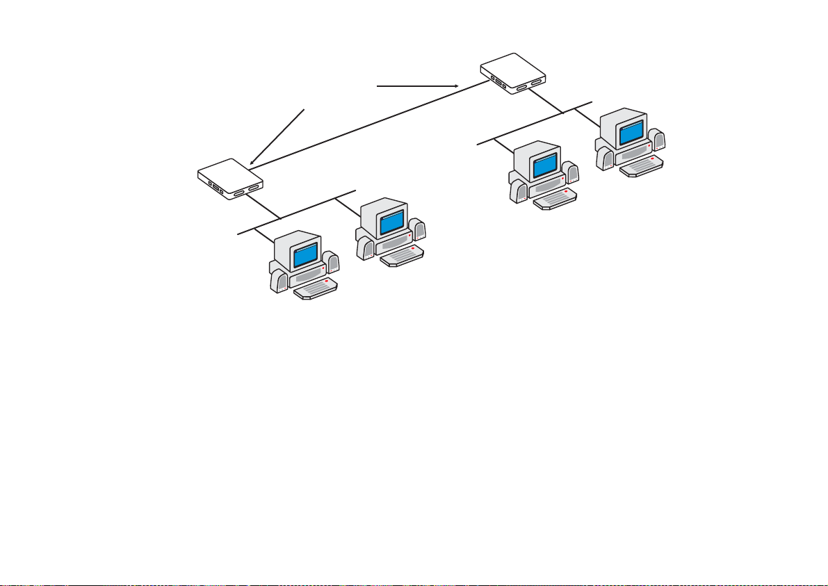
Cyclades-PR4000
Router 2
Router 1
ETH0
Slot 1
10.0.0.3
Unnumbered
Interfaces
Point-to-Point Connection
Slot 3
ETH0
E
192.168.100.1
F
Network 3
B
A
FIGURE 12.2 STATIC ROUTING EXAMPLE 2
Figure 12.2 shows another static routing example to explain the
two routers is a point-to-point connection. Another network could be created, but is not necessary. Both routers
can be assigned unnumbered interfaces, because everything that leaves one router is sent to the other.
To define static routes, enter the menu CONFIG =>STATIC ROUTES =>IP =>ADD ROUTE. A description of the
parameters in this menu, with the configuration for Router 1 in the examples above, is given in the table that
follows.
Network 1
Gateway
or
Interface
parameter. Between the
Chapter 11 - Routing Protocols 93
Page 94

Cyclades-PR4000
Add Static Route Menu CONFIG =>STATIC ROUTES =>IP =>ADD ROUTE
Parameter Description
Destination IP
Address
Address that route will lead to. To configure a default route, type "default" for this
parameter, otherwise enter 0.0.0.0 in both this and the next parameter.
Both Examples
-- for the static route between Router 1 and Network 3, the IP
addre s s is 19 2.168.100.0.
Subnet Mask
Gateway or Interface
Both Examples
Exampl e 1
Exampl e 2
-- To access all hosts in Network 3, its mask, 255.255.255.0, is used.
-- the route is to a gateway.
-- the route is to an interface since unnumbered interfaces are being
used.
Gateway IP Address Applies only when previous parameter is
the router. In
Example 1
, it is 142.10.0.4.
Interface Applies only when previous parameter is
N) that will be unnumbered. In
Example 2
Gateway
Interface
, it is Slot 1.
. It must be an address visible to
. Select the port (Ethernet or slot
Metric Relative cost of this link. Generally measured in number of routers between two IP
addresses.
Is This a Backup
Route?
OSPF Advertises
This Static Route
Indica tes that this route is used as a backup in a multilink circ uit. See section 4.4 for
more information about multilink circuits.
Static routes defined in the router can be advertised by OSPF. Both this parameter
and the parameter CONFIG=>IP=>OSPF=>GLOBAL=>ADVERTISE STATIC
ROUTES must be set to
External Metric Applies when
Both Examples
OSPF Advertises This Static Route
-- 1.
for the route to be advertised.
Yes
is set to
. Defines the metric
Yes
that will be advertised by OSPF.
External Metric-Type Applies when
OSPF Advertises This Static Route
is set to Yes. For
Type 1
, the total
metric of this route is composed of the internal metri c (inside the autonomous system)
and the external metric (provided in the previous paramet e r). For
Type 2
, the total
metric of this route is the value provided in the previous parameter.
Chapter 11 - Routing Protocols 94
Page 95

Cyclades-PR4000
RIP Configuration
CyROS supports three basic types of RIP:
1 RIP1 [RFC 1058]
2 RIP2 with broadcast (compatible with RIP1) [RFC 1723]
3 RIP2 with multicast [RFC 1723]
The primary difference between RIP1 and RIP2 is that only RIP2 advertises subnet masks and next hops. If the
network contains equipment that understands only RIP1 packets, then RIP1 or RIP2 with broadcast should be
used. See RFC 1723, item 3.3 for more details. If only RIP2 is used, RIP2 with multicast is recommended.
Unlike static routes RIP is configured on each interface rather than in a global menu. The menu is the same for all
interfaces and its parameters are presented in the table below.
RIP Menu CONFIG =>INTERFACE =>
<LINK>
=>ROUTING PROTOCOL =>RIP
Parameter Description
Send RIP Causes the router to transmit RIP messages.
Listen RIP Causes the router to accept RIP messages.
RIP2 Authentication Applies if
was chosen in the first two options. Activates RIP message
RIP2
authentication with a password.
RIP2 Authentication
Password
Chapter 11 - Routing Protocols 95
Applies if
RIP2 Authentication
transmitted RIP messages.
is
. Password used for both received and
Active
Page 96

Cyclades-PR4000
OSPF
The OSPF (Open Shortest Path First) routing protocol is significantly more complicated than RIP . The determination
of which protocol is better suited to a given network is beyond the scope of this manual. An example network
using OSPF is given in Figure 12.3.
AREA 1
Router 2
AREA 0
(Backbone)
Router 0
To Another
Autonomous System
Router 1
Link 1
Router 5
Router 3
Router 4
Router 6
AREA 2
AN AUTONOMOUS SYSTEM
Area Border
Routers:
R3, R6, R8
AS Boundary
Router: R5
Router 7
Virtual
Link
AREA 3
Router 8
Router 9
FIGURE 12.3 OSPF EXAMPLE
Chapter 11 - Routing Protocols 96
Page 97

Cyclades-PR4000
First, some definitions:
• An Autonomous System (AS) is a portion of the network that will use a single routing strategy. It is made up
of a backbone area and optionally of non-backbone areas.
• OSPF Areas are sub-systems that have identical routing databases. An area generally has no knowledge of
the routing databases of other areas.
• The Backbone connects areas and contains any routers not contained in another area.
• An Area Border Router connects areas and contains a separate database for each area it is contained in.
• An Autonomous System Boundary Router (ASBR) connects Autonomous Systems. The other Autonomous
System does not necessarily need to use OSPF.
STEP ONE
If using OSPF for the first time, sketch the network and determine which routers will make up the backbone and
each area. Determine if each router is an area border router or an autonomous system boundary router.
OSPF Configuration on the Interface
STEP TWO
Contrary to most other protocols in CyROS, OSPF must first be configured on each interface, then configured in
the CONFIG =>IP =>OSPF menu. Enter into each interface and set the parameters listed in the table.
OSPF Menu CONFIG =>INTERFACE =>
<LINK>
=>ROUTING PROTOCOL =>OSPF
Parameter Description
OSPF on This
Interface
Activates OSPF.
Enable Inactive
is used to temporarily disable the OSPF protocol
without erasing the parameters set below. This is useful when OSPF is first configured,
as the general parameters must be set afterwards in CONFIG=>IP =>OSPF and OSPF
cannot function without them.
Parameters that apply only when
Advertise This NonOSPF Interface
Causes the router to include this interface in its advertisements through other interfaces
(as an external route).
OSPF on This Interface
is
Disabled
.
This table is continued.
Chapter 11 - Routing Protocols 97
Page 98

Cyclades-PR4000
OSPF Menu (continued)
External Metric Defines the metric that will be advertised by OSPF.
External Metric Type For
, the total metric of this route is composed of the internal metric (inside the
Type 1
autonomous system) and the external metric (provided in the previous parameter). For
, the total metric of this route is the value provided in the previous parameter.
Type 2
Parameters that apply only when
OSPF on This Interface
is
Enable
or
Enable I na ctive
.
Area ID Identifies the area to which the interface belongs. Areas are created here, then later
defined in CONFIG=>IP=>OSPF =>AREA. Has the format of an IP address, but is not
linked to any IP address in the system. Small OSPF networks will typically have only
one area (the backb one area represent ed by 0.0.0.0).
Router Priority Priority used by OSPF in multicast networks to elect the designated router. A priority of
1 will make this router the most likely to be chosen. A priority of 2 will make it second
most likely. Set it to 0 (zero) if this router should never be the designated router.
Transit Delay in
Seconds
Estimated transit time in seconds to route a packet through this interface. Use the
preset value (1) or increase the number for slow links
Retransmit Interval * Time in seconds between link-state advertisement retransmissions for adjacencies
belonging to this interface.
Hello Interval * Time in seconds between the hello packets on this interface.
Dead Interval * Inactivity time (seconds) before a neighbor router is considered down.
Poll Interval * Time in seconds between the hello packets sent to an inactive, non-broadcast, multi-
access neighbor.
Password * String of up to 8 characters used to authenticate OSPF packages. The use of this
password is enabled in CONFIG=>IP=>OSPF=>AREA=>AUTHENTICATION TYPE
Metric Defines the cost for normal service. For consis tent routing, this parameter should be
determined in the same manner for all routers in the OSPF Area. Normally, metric cost
is defined as an inverse function of interface throughput (e.g. 1 for 100Mbps, 10 for
10Mbps, 65 for T1, 1785 for 56kbps, etc).
Advertise Secondary
IP Address
Causes the router to advertise additional addresses assigned to this interface. These
are configured in CONFIG => INTERFACE =><LINK> =>NETWORK PROTOCOL =>IP.
* Inside a given area, these 4 parameters should be the same for all routers.
Chapter 11 - Routing Protocols 98
Page 99

Cyclades-PR4000
OSPF Global Configurations
STEP THREE
After completing the OSPF interface configuration for all interfaces (even those that will not use OSPF), navigate
to the OSPF Menu, CONFIG=>IP=>OSPF . Enter into the OSPF Global Commands menu and set the parameters
as indicated in the table below.
OSPF Global Commands Menu CONFIG =>IP =>OSPF =>GLOBAL
Parameter Description
OSPF Protocol Enables OSPF on all interfaces.
Router ID Assigns a unique ID to the router for use by the OSPF protocol. It mu st be one of the
router's IP addresses.
AS Boundary Router An Autonomous System Boundary Router (ASBR) can convert external routes into
OSPF routes. Which external routes is determined through the following parameters.
In the figure, only Router 5 is an ASBR.
The following parameters apply only to
Originate Default
Router will advertise itself as the Default Gateway (DG).
Autonomous System Boundary Routers
.
Gateway
Advertisement
Default Gateway
External Metric
Default Gateway
External Metric-Type
Applies when
Originate Default Gateway Advertisement
is set to
. Defines the
Yes
metric that will be advertised by OSPF.
Applies when
Originate Default Gateway Advertisement
is set to Yes. For
Type 1
total metric of this route is composed of the internal metric (inside the autonomous
system) and the external metric (provided in the previous parameter). For
Type 2
, the
, the
total metric of this route is the value provided in the previous parameter.
Advertise RIP Routes Routes learned through the RIP protocol will be converted to OSPF as external routes.
RIP External Metric Applies when
Advertise RIP routes
is set to
. Defines the metric that will be
Yes
advertised by OSPF.
This table is continued.
Chapter 11 - Routing Protocols 99
Page 100

Cyclades-PR4000
OSPF Global Commands (Continued)
Parameter Description
RIP External MetricType
Applies when
Advertise RIP routes
is set to
Yes
. For
, the total metric of this
Type 1
route is composed of the internal metric (inside the autonomous system) and the
external metric (provided in the previous parameter). For
, the total metric of
Type 2
this route is the value provided in the previous parameter.
Advertise Non-OSPF
interfaces
A router can have both OSPF and non-OSPF interfaces. This option causes the router
to advertise when these non-OSPF interfaces are up or down. When OSPF is
disabled on an interface, the parameter CONFIG=>INTERFACE =>
<LINK>
=>ROUTING PROTOCOL =>OSPF =>ADVERTISE THIS NON-OSPF INTERFACE
for the inte rf a ce to be advert i sed.
Yes
Advertise Static
Routes
must also be set to
Static routes defined in the router will be converted to OSPF. Note that static routes
can be configured individually as advertised or not in the parameter
CONFIG=>STATIC ROUTES=>IP=>ADD ROUTE=>OSPF ADVERTISES THIS
STATIC ROUTE. Both parameters must be
for the route to be advertised.
Yes
STEP FOUR
The next step is to define the areas created in step two. This is done in the OSPF Area Menu.
Area Menu CONFIG =>IP =>OSPF =>AREA
Parameter Description
Area ID Has the format of an IP address, but is not linked to any IP address in the system. Use
the CONFIG=>IP=>OSPF=>L option to see which areas have been defi ned, and use
the area ID here.
Authentication Type Simple password authentication can be used in OSPF. The authentication type should
be the same for all routers in an OSPF Area. If used, the password for each interface
is set in CONFIG=>INTERFACE=>
<INTERFACE>
=>ROUTING PROTOCOL =>OSPF
=>PASSWORD.
This table is continued.
Chapter 11 - Routing Protocols 100
 Loading...