

Page 1

Cyclades-PR2000
Installation Manual
Access Router
Cyclades Corporation
Page 2

Cyclades-PR2000 Installation Manual
Version 1.2 – May 2002
Copyright (C) Cyclades Corporation, 1998 - 2002
We believe the information in this manual is accurate and reliable. However, we assume no responsibility,
financial or otherwise, for any consequences of the use of this Installation Manual.
This manual is published by Cyclades Corporation, which reserves the right to make improvements or changes
in the products described in this manual as well as to revise this publication at any time and without notice to
any person of such revision or change. The menu options described in this manual correspond to version 1.9.7
of the CyROS operating system. This manual is printed horizontally in order to match the electronic (PDF)
format of the Installation Manual, page per page.
All brand and product names mentioned in this publication are trademarks or registered trademarks of their
respective holders.
FCC Warning Statement:
The Cyclades-PR2000 has been tested and found to comply with the limits for Class A digital devices, pursuant
to Part 15 of the FCC rules. These limits are designed to provide reasonable protection against harmful
interference when the equipment is operated in a commercial environment. This equipment generates, uses
and can radiate radio frequency energy and, if not installed and used in accordance with the Installation
Manual, may cause harmful interference to radio communications. Operation of this equipment in a residential
area is likely to cause harmful interference in which case the user is required to correct the problem at his or
her own expense.
Canadian DOC Notice:
The Cyclades-PR2000 does not exceed the Class A limits for radio noise emissions from digital apparatus set
out in the Radio Interference Regulations of the Canadian Department of Communications.
Le Cyclades-PR2000 n’émet pas de bruits radioélectriques dépassant les limites applicables aux appareils
numériques de la classe A prescrites dans le règlement sur le brouillage radioélectrique edicté par le Ministère
des Communications du Canada.
Page 3

Cyclades-PR2000
Table of Contents
CHAPTER 1 HOW TO USE THIS MANUAL ........................................................................................................ 7
Installation Assumptions .................................................................................................................................... 8
Text Conventions ................................................................................................................................................ 8
Icons................................................................................................................................................................... 9
Cyclades Technical Support and Contact Information..................................................................................... 10
CHAPTER 2 WHAT IS IN THE BOX .................................................................................................................. 12
CHAPTER 3 USING CYROS MENUS ................................................................................................... ............ 14
Connection Using the Console Cable and a Computer or Terminal................................................................ 14
Special Keys................................................................................................................................................. 16
The CyROS Management Utility...................................................................................................................... 17
CHAPTER 4 STEP-BY-STEP INSTRUCTIONS FOR COMMON APPLICATIONS...........................................19
Example 1 Connection to an Internet Access Provider via Modem................................................................ 19
Example 2 A LAN-to-LAN Example Using Frame Relay ................................................................................ 27
Example 3 Link Backup................................................................................................................................... 35
CHAPTER 5 CONFIGURATION OF THE ETHERNET INTERFACE ................................................................ 41
The IP Network Protocol .................................................................................................................................. 41
IP Bridge....................................................................................................................................................... 43
Other Parameters ............................................................................................................................................. 44
CHAPTER 6 THE SWAN AND ASYNC INTERFACES...................................................................................... 45
CHAPTER 7 NETWORK PROTOCOLS............................................................................................................. 48
Table of Contents 3
Page 4

Cyclades-PR2000
The IP Protocol................................................................................................................................................. 49
The Transparent Bridge Protocol..................................................................................................................... 51
CHAPTER 8 DATA-LINK PROTOCOLS (ENCAPSULATION)........................................................................... 52
PPP (The Point-to-Point Protocol) ................................................................................................................... 52
CHAR ............................................................................................................................................................... 54
PPPCHAR ........................................................................................................................................................ 55
HDLC................................................................................................................................................................ 55
Frame Relay..................................................................................................................................................... 55
X.25 .................................................................................................................................................................. 60
X.25 with PAD (Packet Assembler/Disassembler)........................................................................................... 63
CHAPTER 9 ROUTING PROTOCOLS .............................................................................................................. 64
Routing Strategies............................................................................................................................................ 64
Static Routing ............................................................................................................................................... 64
Dynamic Routing .......................................................................................................................................... 64
Static Routes.................................................................................................................................................... 65
RIP Configuration............................................................................................................................................. 68
OSPF................................................................................................................................................................ 69
OSPF Configuration on the Interface ........................................................................................................... 70
OSPF Global Configurations ........................................................................................................................ 72
BGP-4 Configuration ........................................................................................................................................ 76
CHAPTER 10 CYROS, THE OPERATING SYSTEM.........................................................................................87
Creation of the host table ................................................................................................................................. 87
Table of Contents 4
Page 5

Cyclades-PR2000
Creation of user accounts and passwords....................................................................................................... 87
IP Accounting ................................................................................................................................................... 89
CHAPTER 11 NAT (NETWORK ADDRESS TRANSLATION) .......................................................................... 90
Types of Address Translation ....................................................................................................................... 92
CHAPTER 12 RULES AND FILTERS ................................................................................................................ 96
Configuration of IP Filters................................................................................................................................. 96
Traffic Rule Lists ............................................................................................................................................. 105
CHAPTER 13 IPX (INTERNETWORK PACKET EXCHANGE) .......................................................................111
Enabling IPX ................................................................................................................................................... 112
Configuring the Ethernet Interface ................................................................................................................. 112
Configuring Other Interfaces.......................................................................................................................... 112
PPP..............................................................................................................................................................112
Frame Relay ................................................................................................................................................113
X.25 .............................................................................................................................................................113
Routing ........................................................................................................................................................... 113
The SAP (Service Advertisement Protocol) Table ......................................................................................... 114
CHAPTER 14 VIRTUAL PRIVATE NETWORK CONFIGURATION................................................................. 115
APPENDIX A TROUBLESHOOTING............................................................................................................... 120
What to Do if the Login Screen Does Not Appear When Using a Console. .................................................. 120
What to Do if the Router Does Not Work or Stops Working. .........................................................................121
Testing the Ethernet Interface........................................................................................................................ 122
Table of Contents 5
Page 6

Cyclades-PR2000
Testing the WAN Interfaces............................................................................................................................ 123
APPENDIX B HARDWARE SPECIFICATIONS ............................................................................................... 126
General Specifications ................................................................................................................................... 126
External Interfaces ......................................................................................................................................... 127
The WAN Interfaces ................................................................................................................................... 127
The LAN Interface ...................................................................................................................................... 127
The Asynchronous Interface ...................................................................................................................... 128
The Console Interface ................................................................................................................................ 128
Cables ............................................................................................................................................................ 129
The Straight-Through Cable....................................................................................................................... 129
DB-25 - M.34 Adaptor ................................................................................................................................. 130
The ASY/Modem Cable.............................................................................................................................. 131
The Cross Cable......................................................................................................................................... 131
DB-25 Loopback Connector....................................................................................................................... 133
APPENDIX C CONFIGURATION WITHOUT A CONSOLE ............................................................................. 134
Requirements................................................................................................................................................. 134
Procedure....................................................................................................................................................... 134
INDEX ................................................................................................................................................................ 135
Table of Contents 6
Page 7

Cyclades-PR2000
CHAPTER 1 HOW TO USE THIS MANUAL
Three Cyclades manuals are related to the PR2000.
1 The Quick Installation Manual -- provided with the router,
2 The Installation Manual -- available electronically on the Cyclades web site,
3 The CyROS Reference Guide -- also available electronically on the Cyclades web site.
CyROS stands for the Cyclades Routing Operating System. It is the operating system for all Cyclades Power
Routers (PR1000, PR2000, PR3000, and PR4000). The CyROS Reference Guide contains complete information
about the features and configuration of all products in the PR line.
CyROS is constantly evolving, and the menus in this manual might be slightly different from the menus in the
router. The latest version of all three manuals (and the latest version of CyROS) can be downloaded from Cyclades’
web site. All manuals indicate on the second page the manual version and the corresponding version of CyROS.
This manual should be read in the order written, with exceptions given in the text.
-
Chapter 2 - What is in the Box
Chapter 3 -Using Menus
-
explains how the router should be connected.
describes CyROS menu navigation.
Chapter 4 -Step-by-Step Instructions for Common Applications - guide to configuration with detailed examples.
Chapters 5 to 9- Basic router configuration information for applications that do not fit any of the examples in
chapter 4.
Chapter 10 - CyROS - shows how to set router specific parameters and create lists of hosts and users.
Chapter 11 - Network Address T ranslation - describes CyROS’ NA T implementation.
Chapter 1 - How To Use This Manual
7
Page 8

Cyclades-PR2000
Chapter 12 - Filters and Rules - demonstrates how to protect your router from undesired traffic.
Chapter 13 - IPX - presents the hidden menus available only in routers with IPX activated.
Chapter 14 - Virtual Private Network - describes CyROS’ VPN implementation.
Appendix A - Troubleshooting - provides solutions and tests for typical problems.
Appendix B - Hardware Specifications.
Appendix C - Configuration Without a Console.
Installation Assumptions
This Installation Manual assumes that the reader understands networking basics and is familiar with the terms and
concepts used in Local Area and Wide Area Networking.
Text Conventions
Common text conventions are used. A summary is presented below:
Chapter 1 - How To Use This Manual
8
Page 9

Cyclades-PR2000
Convention Description
CONFIG=>INTERFACE=>L A combination of menu items, with the last being either a menu item, a
parameter, or a command. In this example, L lists the interface configuration.
<INTERFACE>
A variable menu item that depends on hardware options or a choice of
hardware or software options.
IP Address
Screen Text
A parameter or menu item referenced in text, without path prepended.
Screen Text
<ESC>, <Enter> Simbols representing special keyboard keys.
Icons
Icons are used to draw attention to important text.
Icon Meaning Why
What is Wro ng? When an error is common, text with this icon will mention the symptoms and
how to resolve the problem.
Where Can I Find
More Information?
Caution! Not following instructio ns can result in damage to the hardware. Text with
Reminder. Certain instructions must be f ollowed in order. Text with this icon will ex plain
Chapter 1 - How To Use This Manual
CyROS contains many features, and sometimes related material must be
broken up int o digestible piec es. Text with t his icon will indicate the releva nt
section.
this icon will warn when dam age is possible.
the proper steps.
9
Page 10
Cyclades-PR2000
Cyclades Technical Support and Contact Information
All Cyclades products include limited free technical support, software upgrades and manual updates.
These updates and the latest product information are available at:
http://www.cyclades.com
ftp://ftp.cyclades.com/pub/cyclades
Before contacting us for technical support on a configuration problem, please collect the information
listed be low.
• The Cyclades product name and model.
• Applicable hardware and software options and versions.
• Information about the environment (network, carrier, etc).
• The product configuration. Print out a copy of the listing obtained by selecting INFO=>SHOW
CONFIGURATION=>ALL.
• A detailed description of the problem.
• The exact error or log messages printed by the router or by any other system.
• The Installation Guide for your product.
• Contact information in case we need to contact you at a later time.
In the United States and Canada, contact technical support by phone or e-mail:
Phone: (510) 770-9727 (9:00AM to 5:00PM PST)
Fax: (510) 770-0355
E-mail: support@cyclades.com
Outside North America, please contact us through e-mail or contact your local Cyclades distributor or representative.
10Chapter 1 - How to Use This Manual
Page 11

Cyclades-PR2000
The mailing address and general phone numbers for Cyclades Corporation are:
Cyclades Corporation
Phone: + 01 (510) 770-9727
Fax: + 01 (510) 770-0355
41829 Albrae Street
Fremont, CA 94538
USA
11Chapter 1 - How to Use This Manual
Page 12
Cyclades-PR2000
WAN 1
WAN 2
Power
Plug
On
Off
Console
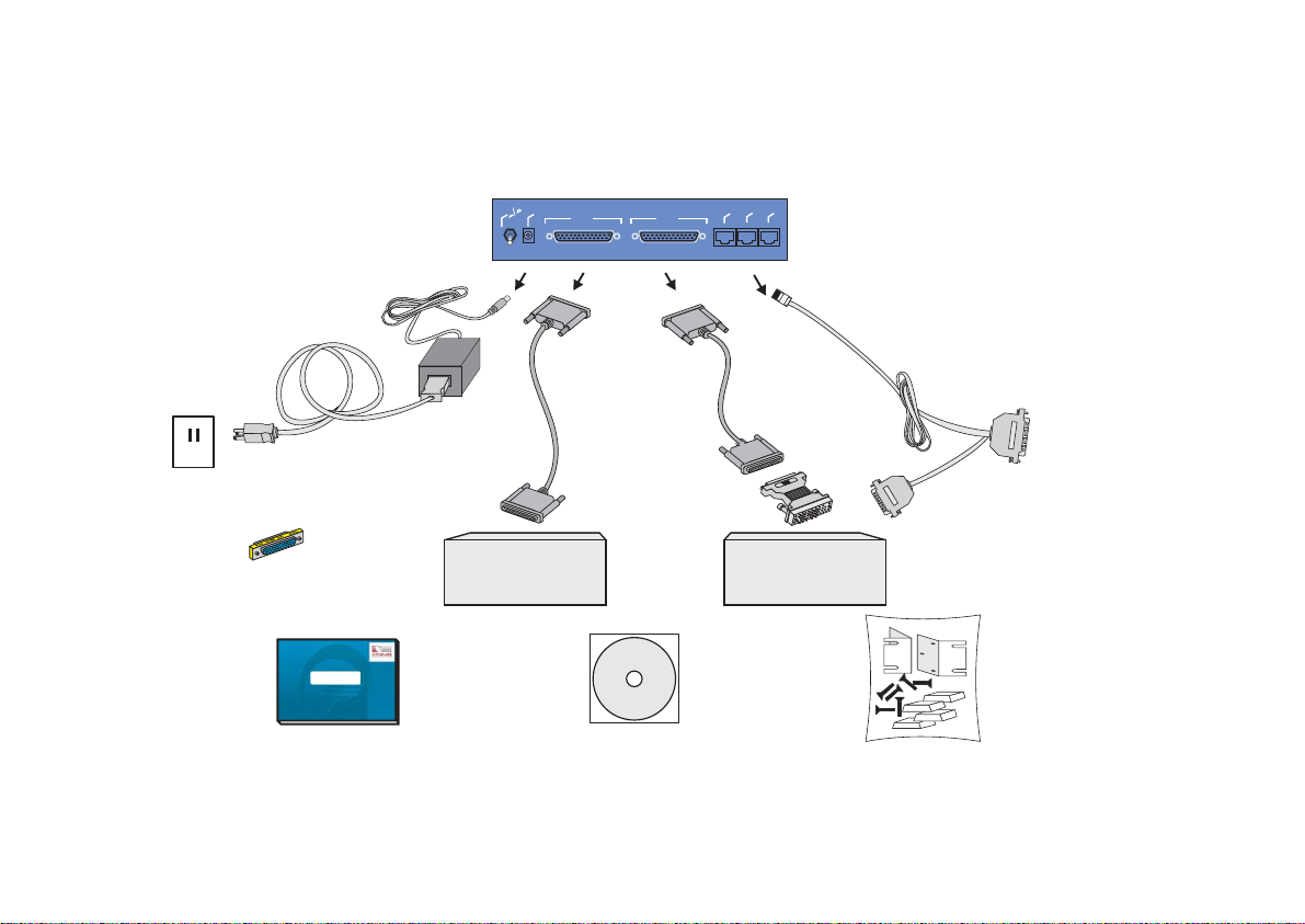
CHAPTER 2 WHAT IS IN THE BOX
The Cyclades-PR2000 is accompanied by the following accessories:
Back Panel of PR2000
g
u
l
f
f
P
O
r
e
w
o
n
P
O
WAN 1
WAN 2
Ethernet
Cyclades- PR2000
onsole
Asynch.
C
Power Cable
To Wall Outlet
Gender Changer
Cyclades-PR2000
Quick Installation Manual
DB-25
Male
Cable
Labeled
Cable
Labeled
“Paralelo”
“Paralelo”
DB-25
Male
RS-232 Modem
with DB-25
Interface
V.35
Adaptor
V.35
DSU/CSU
with M.34
Interface
CD-Rom Containing
Documentation
Console Cable
Labeled “Conf”
To COM Port
of Computer
DB-25
DB-9
Mounting Kit
FIGURE 2.1 CYCLADES-PR2000 AND CABLES
Chapter 2 - What is in the Box 12
Page 13
Cyclades-PR2000
WAN 1
WAN 2
Power
Plug
On
Off
Quick Installation Manual • Console Cable
•
• Installation Manual & Reference Guide (on CD) • Mounting Kit
• Two straight-through cables • Power Source & Cable
• Two V.35 Adapters • Gender Changer
Figure 2.1 shows which cables are used for each type of modem and how everything should be connected.
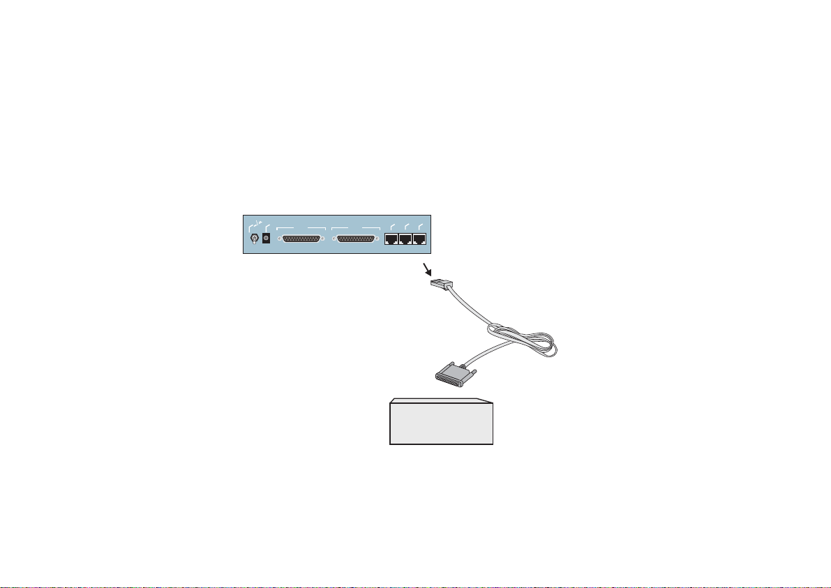
The pinout diagrams of these cables are provided in Appendix B of the Installation Manual. The RJ-45 to DB25 adapter cable, which must be purchased separately, is shown in Figure 2.2.
Back Panel of PR2000
g
lu
P
r
e
w
o
P
On Off
WAN 1
WAN 2
Ethernet
Cyclades- PR2000
Asynch.
Console
RJ-45 Male
RJ-45 TO DB-25
Adapter
DB-25 Male
RS-232 Modem
with DB-25
Interface
FIGURE 2.2 HOW TO CONNECT THE RJ-45 TO DB-25 ADAPTER CABLE
Chapter 2 - What is in the Box 13
Page 14

Cyclades-PR2000
Chapter 3 Using CyROS Menus
This chapter explains CyROS menu navigation and special keys. There are four ways to interact with CyROS:
• Traditional menu interface using a console or Telnet session,
• CyROS Management Utility based on interactive HTML pages,
• SNMP (explained in the CyROS Reference Manual).
Connection Using the Console Cable and a Computer or Terminal
The first step is to connect a computer or terminal to the router using the console cable. If using a computer,
HyperTerminal can be used in the Windows operating system or Kermit in the Unix operating system. The
terminal parameters should be set as follows:
• Serial Speed: 9600 bps
• Data Length: 8 bits
• Parity: None
• Stop Bits: 1 stop bit
or
• Flow Control: Hardware flow control
none
[PR2000] login : super
[PR2000] Password : ****
Cyclades Router (Router Name) – Main Menu
1 – Config 2 – Applications 3 – Logout
4 – Debug 5 – Info 6 – Admin
Select Option ==>
FIGURE 3.1 LOGIN PROMPT AND MAIN MENU
Chapter 3 - Using CyROS Menus 14
Page 15

Cyclades-PR2000
Once the console connection is correctly established, a Cyclades banner and login prompt should appear on
the terminal screen. If nothing appears, see the first section of the troubleshooting appendix for help. The
second step is to log in. The preset super-user user ID is “super” and the corresponding preset password is
“surt”. The password should be changed as soon as possible, as described in chapter 10 of the installation
manual and at the end of every example in chapter 4. The login prompts and main menu are shown in Figure
3.1.
All menus have the following elements:
• Title – In the example in Figure 3.1: “Main Menu”.
• Prompt – The text: “Select Option ==>”.
• Options –The menu options, which are selected by number.
• Router Name – The default is the name of the product. Each router can be renamed by the super user for
easier identification.
Menus can also be navigated using a short-cut method. This method must be activated first by choosing a
shortcut character (“+” in the example that follows) in the CONFIG =>SYSTEM =>ROUTER DESCRIPTION
menu. Typing 4+1+1 at the main-menu prompt, for example, is equivalent to choosing option 4 in the main
menu (Debug), then choosing option 1 in the debug menu (Trace), then choosing option 1 in the trace menu
(Driver Trace). In addition to menus, some screens have questions with letter choices. In the line below,
several elements may be identified:
lmi-type((A)NSI, (G)roup of four, (N)one )[ANSI]:
• Parameter description – The name of the parameter to be configured, in this case “lmi-type”.
• Options – Legal choices. The letter in parentheses is the letter that selects the corresponding option.
• Current value – The option in square brackets is the current value.
Pressing <Enter> without typing a new value leaves the item unchanged.
Chapter 3 - Using CyROS Menus 15
Page 16

Cyclades-PR2000
Special Keys
<Enter> or <Ctrl+M> These keys are used to end the input of a value.
<ESC> or <Ctrl+I> These keys are used to cancel a selection or return to the previous menu. In
some isolated cases, this key jumps to the next menu in a series of menus at the
same level.
<Backspace> or <Ctrl+H>These keys have the expected effect of erasing previously typed characters.
L When available, this option displays the current configuration. For example, in
the Ethernet Interface Menu, “L” displays the Ethernet configuration.
<Ctrl+L
>
This key combination displays the same information as the L option, above, but
works like a toggle switch to allow display of one page of information at a time or
display the entire configuration without page breaks.
<Ctrl+C
>
This key combination disables any traces activated in the Debug Menu.
On leaving a menu where a change in configuration was made, CyROS will ask whether or not the change is to
be saved:
(D)iscard, save to (F)lash, or save to (R)un configuration:
Selecting
Discard
will undo all changes made since the last time the question was asked. Saving to
Flash
memory makes all changes permanent. The changes are immediately effective and are saved to the
configuration vector in flash memory. In this case, the configuration is maintained even after a router reboot.
Run
Saving only to the
configuration makes all changes effective immediately, but nothing is saved
permanently until explicitly saved to flash (which can be done with the option ADMIN =>WRITE
CONFIGURATION=>TO FLASH).
The menus and parameter lists are represented in this manual by tables. The first column contains the menu
item or the parameter, and the second column contains its description.
This menu interface is also available via Telnet if one of the interfaces has been connected and configured.
The menu interface is the same as that described earlier in this section. Using Telnet instead of a console for
the initial Ethernet configuration is discussed in Appendix C of the Installation Manual.
Chapter 3 - Using CyROS Menus 16
Page 17
Cyclades-PR2000
WAN 1
WAN 2
Power
Plug
On
Off
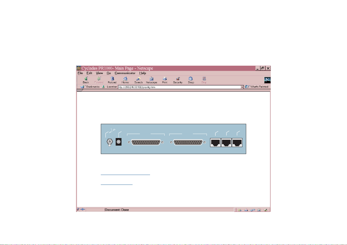
The CyROS Management Utility
After one of the interfaces has been connected and configured, there is another way to interact with CyROS.
Type the IP address in the location field in an HTML browser of a PC connected locally or remotely through the
configured interface. A super-user ID and password will be requested (these are the same ID and password
used with the line-terminal interface). A clickable image of the router back panel will apear, as shown in Figure
3.2.
Cyros Management Utility
Firmware version: Cyclades-PR2000: CyROS V_2.0.0
f
Of
Power Plug
On
WAN 1
WAN 2
Configuration Menu Interface (Text Mode)
End HTTP session
Ethernet
Cyclades - PR2000
Asynch.
Console
FIGURE 3.2 CYROS MANAGEMENT UTILITY HOME PAGE
Chapter 3 - Using CyROS Menus 17
Page 18

Cyclades-PR2000
The link
Configuration Menu Interface
will present an HTML version of the CyROS Main Menu, described
previously. Clicking on an interface will show its current status and some additional information. Clicking on
End HTTP Session
will terminate the connection.
Chapter 3 - Using CyROS Menus 18
Page 19
Cyclades-PR2000
CHAPTER 4 STEP-BY-STEP INSTRUCTIONS FOR COMMON APPLICATIONS
This chapter provides detailed examples that can be used as models for similar applications. Turn to the
example that is closest to your application, read the explanations, and fill in the blank spaces with parameters
appropriate to your system. At the end of the section, you should have listed all the parameters needed to
configure the router. At that point, read chapter 3 if you have not already, and configure your router with help
from later chapters of the Installation Manual, when needed.
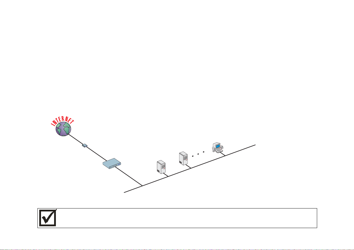
Example 1 Connection to an Internet Access Provider via Modem
This section will guide you through a complete router installation for the connection of a LAN to an Internet
access provider via PPP. The configuration of NAT (Network Address Translation) will also be shown. Figure
4.1 shows the example system used in this section. Spaces have been provided next to the parameters
needed for the configuration where you can fill in the parameters for your system. Do this now before
continuing.
Speed: 38.4k
_______
RS-232 Modem
_______
PR2000
SWAN
ETH0
Host
PC
Host
192.168.0.30
_______
192.168.0.11
Network IP:
192.168.0.0
Network Mask:
255.255.255.0
________
192.168.0.10 _______
192.168.0.1_______
FIGURE 4.1 CONNECTION TO ACCESS PROVIDER USING A SWAN INTERFACE AND A MODEM
Please read the entire example and follow the instructions before turning the router on. The router is
programmed to log the super user off after 10 minutes of inactivity . A ll data not explic itly saved to me mory
is then lost. Collecting the data
configuring the router will likely cause delays and frustration.
while
19Chapter 4 - Step-by-Step Instructions
Page 20

Cyclades-PR2000
STEP ONE
The first step is to determine the parameters needed to configure the Ethernet interface (ETH0). The
parameters in the Network Protocol Menu (IP) are shown in Figure 4.2. Fill in the blanks for your application in
the right-most column. These parameters will be entered into the router later, after all parameters have been
chosen. Each parameter in this menu is explained in more detail in chapter 5 of the Installation Manual.
CONFIG=>INTERFACE=>ETHERNET=>NETWORK PROTOCOL=>IP
Menu
Parameter Example Your Application
Active or Inactive Active enables IP communication (IPX
and Transparent Bridge are not used in
this example).
Interface Numbered
Numbered
/Unnumbered
Primary IP Address 192.168.0.1
Subnet Mask 255.255.255.0
Secondary IP
0.0.0.0 for none.
Address
IP MTU Use the preset value, 1500. This
determines whether or not a given IP
datagram is fragmented.
NAT Local
ICMP Port Inactive
Incoming Rule List None, filters are not included in this
example.
Outgoing Rule List
Name
None, filters are not included in this
example.
Proxy ARP Inactive
IP Bridge Inactive
FIGURE 4.2 ETHERNET NETWORK PROTOCOL MENU PARAMETERS
20Chapter 4 - Step-by-Step Instructions
Page 21

Cyclades-PR2000
STEP TWO
No more parameters are necessary for the Ethernet interface. The other interface to be configured is the
SWAN. The SWAN physical media parameters are shown in Figure 4.3. Fill in the values for your application.
The SWAN configuration is described in more detail in chapter 6 of the Installation Manual.
CONFIG=>INTERFACE=>SWAN=>PHYSICAL
Menu
Parameter Example Your Application
Mode Asynchronous
Speed 38.4k
FIGURE 4.3 SWAN PHYSICAL MENU PARAMETERS
STEP THREE
The network protocol parameters, shown in Figure 4.4, are similar to those for the Ethernet interface. Fill in the
parameters for your network in the right-most column.
21Chapter 4 - Step-by-Step Instructions
Page 22

Cyclades-PR2000
CONFIG=>INTERFACE=>SWAN=>NETWORK PROTOCOL=>IP
Menu
Parameter Example Your Application
Active or Inactive Active enables IP communication (IPX and
Transparent Bridge are not used in this
example).
Interface Unnumbered/
Numbered
Numbered
Primary IP Address 0.0.0.0 (This number will be assigned by the
Access Provider dynamically.)
Subnet Mask 255.0.0.0
Secondary IP Address 0.0.0.0 for none
IP MTU Use the preset value, 1500. This determines
whether or not a given IP datagram is
fragmented.
NAT
Global A ssigned
because the IP address of
the SWAN interface will be assigned
dynamically.
Enable Dynamic Local IP
Address
Yes, because the IP address of the SWAN
interface will be assig ne d dynam ic al l y.
Remote IP Address Type Any
Remote IP Address 0.0.0.0
ICMP Port Inactive
Incoming Rule List Name None, filters are not included in this example.
Outgoing Rule List Name None, filters are not included in this example.
Routin g o f Broadcas t
Inactive
Messages
FIGURE 4.4 SWAN NETWORK PROTOCOL (IP) MENU PARAMETERS
22Chapter 4 - Step-by-Step Instructions
Page 23

Cyclades-PR2000
STEP FOUR
The Encapsulation parameters for PPP are less straight-forward. Many of them are based on decisions that
cannot be shown in a diagram. Fortunately, the choices made here will mostly effect the performance of the
link, rather than whether it works or not. Fill in the parameters appropriate for your system, consulting chapter
8 of the Installation Manual for more information if necessary.
CONFIG=>INTERFACE=>SWAN=>ENCAPSULAT ION=>PPP
Menu
Parameter Example Your Application
MLPPP
PPP Inactivity
Timeout
Enable Van Jacobson
No
so that the connection is never
None
broken.
No
IP Header
Compression
Disable LCP Ec ho
No
Requests
Edit ACCM No Value. This will depend on the
modem used.
Time Interval to Send
Use the preset value, one.
Config Requests
Enable Predictor
No
Compression
Connection Type Dial-Out
FIGURE 4.5 PPP ENCAPSULATION MENU PARAMETERS
23Chapter 4 - Step-by-Step Instructions
Page 24

Cyclades-PR2000
STEP FIVE
A static route must be added to tell the router that all traffic not intended for the local LAN should be sent to the
Access Provider. Chapter 9 of the Installation Manual explains static routes and other routing methods
available in CyROS. Fill in the spaces in Figure 4.6 with the values for your application.
CONFIG=>STATIC ROUTES=>IP=>ADD ROUTE
Menu
Parameter Example Your Application
Destination IP Address Type in the word "DEFAULT".
Gatewa y or Int er f ace
Interface
, because the IP addresses
are not known at configuration time.
Interface Slot 1 (SWAN) in the example.
Is This a Backup Route? No
OSPF Advertises This
No
Static Route
FIGURE 4.6 STATIC ROUTE MENU PARAMETERS
STEP SIX
NAT must now be activated. There are two varieties of NAT: Normal and Expanded. This example uses the
Normal NAT Mode. The other mode is explained in the chapter on NAT in the Installation Manual.
Menu CONFIG =>SECURITY =>NAT =>GENERAL
Parameter Example Your Application
Nat Status Enabled
Nat Mode Normal
Disable Port Translation No
FIGURE 4.7 NAT GENERAL PARAMETERS
24Chapter 4 - Step-by-Step Instructions
Page 25

Cyclades-PR2000
STEP SEVEN
NAT parameters will now be determined for routing outside of the local LAN. Network Address Translation
maps the local IP addresses, registered in the local address range menu below, to the one global IP address
assigned by the access provider. Local IP addresses not indicated in this menu will be discarded.
Menu CONFIG =>SECURITY =>NAT =>LOCAL ADDRESS =>ADD RANGE
Parameter Example Your Application
First IP Address 192.168.0.10
Last IP Address 192.168.0.30
FIGURE 4.8 NAT LOCAL ADDRESS RANGE MENU PARAMETERS
The factory preset values for all other NAT parameters are appropriate for this example.
STEP EIGHT
Now that the parameters have been defined, enter into each menu described above, in the order presented
(read chapter 3, Using Menus, if you have not done so already). Set the parameters in each menu according
to the values you wrote in the figures above. Save the configuration to flash memory at each step when
requested — configurations saved in run memory are erased when the router is turned off. If you saved part of
the configuration to run memory for some reason, save to flash memory now using the menu option ADMIN
=>WRITE CONFIGURATION =>TO FLASH.
STEP NINE
The Ethernet interface can be tested as described in the troubleshooting appendix. The SWAN interface can
be tested in a similar manner. At this point, you should create a backup of the configuration file (in binary) and
print out a listing of the configuration.
25Chapter 4 - Step-by-Step Instructions
Page 26

Cyclades-PR2000
Instructions for creating a backup of the configuration file.
Use the menu option ADMIN =>WRITE CONFIGURATION =>TO FTP SERVER. Fill in the IP address of the
computer where the configuration file should be saved, the file name, the directory name, and the user account
information. This configuration file can later be downloaded with the ADMIN =>LOAD CONFIGURATION
=>FTP SERVER option.
Instructions for listing the configuration.
The menu option INFO =>SHOW CONFIGURATION =>ALL will list to the terminal screen the configuration of
the router. This can be saved in a text file and/or printed on a printer.
26Chapter 4 - Step-by-Step Instructions
Page 27
Cyclades-PR2000
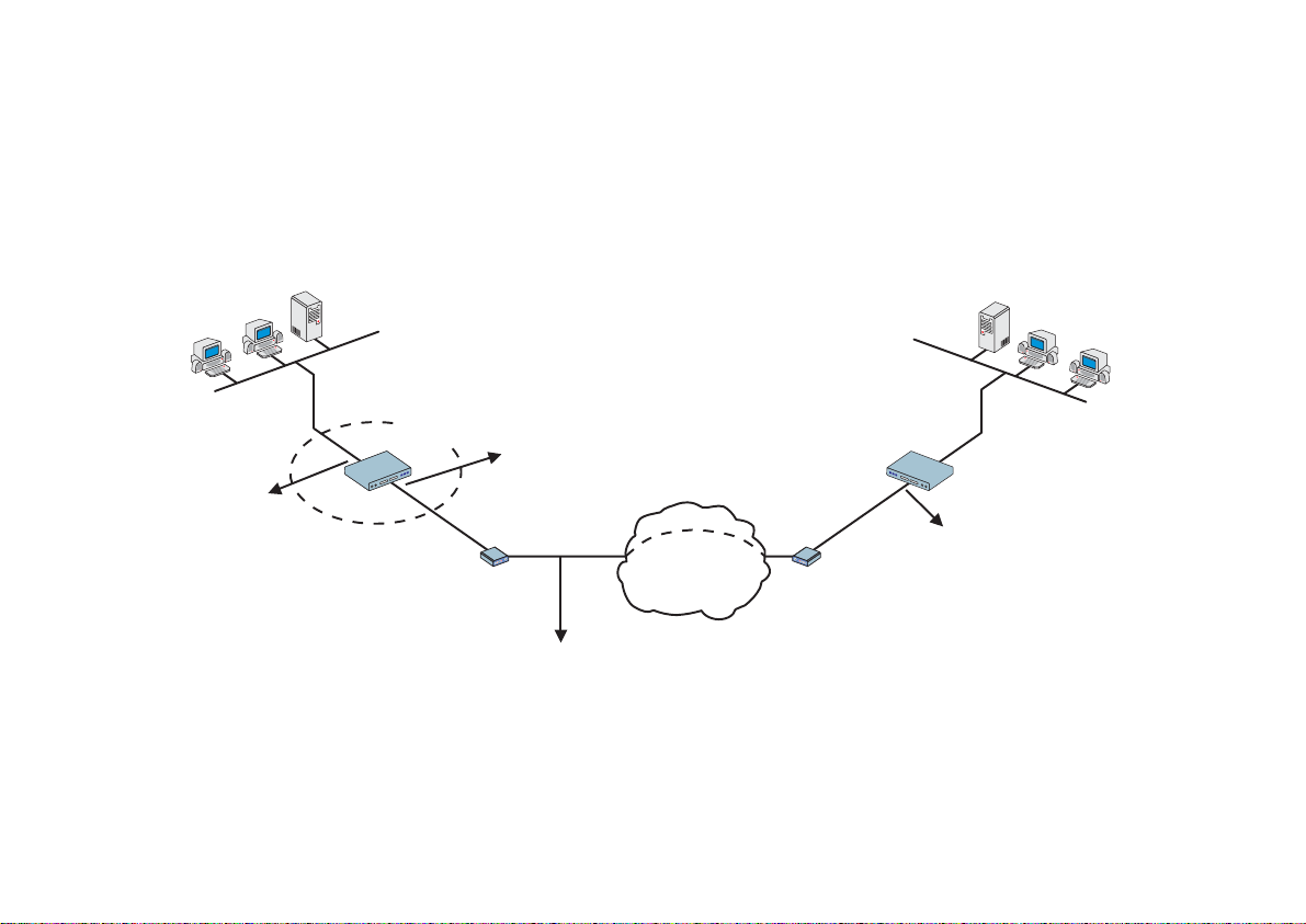
Example 2 A LAN-to-LAN Example Using Frame Relay
This section will guide you through a complete router installation for the connection of two LANs via Frame
Relay. Figure 4.9 shows the example system used in this section. Spaces have been provided next to the
parameters needed for the configuration where you can fill in the parameters for your system. Do this now
before continuing.
Central Office's
LAN
Network IP: 100.130.130.0
________
Mask: 255.255.255.0
________
Network IP: 15.0.0.0
_______
Mask :255.255.255.0
Remote Site’s
________
PR2000
ETH0
200.240.230.2
PR2000
________
100.130.130.1
________
SWAN
V.35 DSU/CSU
________
_ _ _ 128 Kbps
Connection
16
Public
Frame Relay
Network
200.240.230.1
________
Network IP: 200.240.230.0________
Mask :255.255.255.240________
FIGURE 4.9 CENTRAL OFFICE AND REMOTE SITE CONNECTED USING SWAN INTERFACES
LAN
27Chapter 4 - Step-by-Step Instructions
Page 28

Cyclades-PR2000
STEP ONE
The first step is to determine the parameters needed to configure the Ethernet interface (ETH0). The
parameters in the Network Protocol Menu (IP) are shown in Figure 4.10. Fill in the blanks for your application in
the right-most column. These parameters will be entered into the router later, after all parameters have been
chosen. Each parameter in this menu is explained in more detail in chapter 5 of the Installation Manual.
CONFIG=>INTERFACE=>ETHERNET=>NETWORK PROTOCOL=>IP
Menu
Parameter Example Your Application
Active or Inactive Active enables IP communication (IPX and
Transparent Bridge are not used in this
example).
Interface Unnumbered Numbered
Primary IP Address 100.130.130 .1
Subnet Mask 255.255.255.0
Secondary IP Address 0.0.0.0 for none.
IP MTU Use the preset value, 1500. This determines
whether or not a given IP datagram is
fragmented.
NAT Global, because NAT is not being used in this
example.
ICMP Port Inactive
Incoming Rule List None, filters are not included in this example.
Outgoing Rule List Name None, filters are not included in this example.
Proxy ARP Inactive
IP Bridge Inactive
FIGURE 4.10 ETHERNET NETWORK PROTOCOL MENU PARAMETERS
28Chapter 4 - Step-by-Step Instructions
Page 29

Cyclades-PR2000
STEP TWO
No more parameters are necessary for the Ethernet interface. The other interface to be configured is the
SWAN in slot 1. The SWAN physical media parameters are shown in Figure 4.11. Fill in the values for your
application. The SWAN configuration is described in more detail in chapter 6 of the Installation Manual.
CONFIG=>INTERFACE=>SWAN=>PHYSICAL
Menu
Parameter Example Your Application
Mode Synchronous.
Clock Source When the interface is connected to a
DSU/CSU, the
Clock Source
is
External
.
Media for SWAN Cable V.35 in the example because the DSU/CSU
is V.35. The type of cable is detected by the
router, so if the correct cable is connected to
the DSU/CSU the router will choose this
value as the default.
FIGURE 4.11 SWAN PHYSICAL MENU PARAMETERS
29Chapter 4 - Step-by-Step Instructions
Page 30

Cyclades-PR2000
STEP THREE
The network protocol parameters, shown in Figure 4.12, are similar to those for the Ethernet interface. Fill in
the parameters for your network in the right-most column.
CONFIG=>INTERFACE=>SWAN=>NETWORK PROTOCOL=>IP
Menu
Parameter Example Your Application
Active or Inactive Active enables IP communication (IPX and
Transparent Bridge are not used in this
example).
Interface Unnumbered/
Numbered
Numbered
Primary IP Address 200.240.230 .2
Subnet Mask 255.255.255.240 is the mask in the
example.
Secondary IP Address 0.0.0.0 for none.
IP MTU Use the preset value, 1500. This
determines whether or not a given IP
datagram is fragmented.
NAT Global, because NAT is not being used in
this example.
ICMP Port Inactive
Incoming Rule List None, filters are not included in this
example.
Outgoing Rule List Name None, filters are not included in this
example.
Routin g o f Broadcas t
Inactive
Messages
FIGURE 4.12 SWAN NETWORK PROTOCOL (IP) MENU PARAMETERS
30Chapter 4 - Step-by-Step Instructions
Page 31

Cyclades-PR2000
STEP FOUR
The Encapsulation parameters for Frame Relay are less straight-forward. Many of them are based on
decisions that cannot be shown in a diagram. Fortunately, the choices made here will mostly effect the
performance of the link, rather than whether it works or not. Fill in the parameters appropriate for your system,
consulting chapter 8 of the Installation Manual for more information if necessary.
CONFIG=>INTERFACE=>SWAN=>ENCAPSULATION=>FRAME RELAY
Menu
Parameter Example Your Application
SNAP IP
Inactive
for the example. The router on the
sending end must be using the same header
type (NLPID or SNAP) as the router on the
receiving end.
LMI ANSI for the example. This must also be
the same as the router on the receiving end.
T391 Ten seconds, the interval between the LMI
Status Enquiry messages.
N391 Six.
N392 Three.
N393 Four. This value must be larger than N392.
CIR 90 percent. 100 minus this number is the
percentage of total bandwidth that may be
discarded if the network is congested.
Bandwidth Reservation Inactive. Traffic control will not be covered
in this example
FIGURE 4.13 FRAME RELAY ENCAPSULATION MENU PARAMETERS
At the end of the parameter list shown above, the DLCI menu appears. Choosing Add DLCI will lead to the
parameters shown in Figure 4.14. The <ESC> key used at any time during the Frame Relay encapsulation
parameter list will also bring up the DLCI menu. A DLCI entry must be created for every remote Frame Relay
network to be contacted. In the example, only one is shown.
31Chapter 4 - Step-by-Step Instructions
Page 32

Cyclades-PR2000
CONFIG=>INTERFACE=>SWAN=>ENCAPSULATION=>FRAME RELAY=><ESC>=>ADD DLCI
Menu
Parameter Example Your Application
DLCI Number Sixteen. This number is supplied by the
Public Frame Relay network provider.
Frame Relay Address Map
which ma ps one IP addre ss t o this
Static,
DLCI.
IP Address 200.240.230.1
Enable Predictor
Compression
Yes, if Cyclades routers are used on both
ends of the link and Predictor Compression
is enabled on both routers. This feature is
effective only for links running at speeds
under 2 Mbps.
Number of Bits for
Compression
Sixtee n when both ro uters are of t he P R
line. Ten must be used if the other router is
a PathRouter.
FIGURE 4.14 DLC CONFIGURATION MENU PARAMETERS
STEP FIVE
Now that the central office’s LAN has been defined, a route must be added to tell the router that the remote
site’s LAN is at the other end of the line. Creating a static route is the simplest way to do this. Chapter 9 of the
Installation Manual explains static routes and other routing methods available in CyROS. Fill in the spaces in
Figure 4.15 with the values for your application.
32Chapter 4 - Step-by-Step Instructions
Page 33

Cyclades-PR2000
CONFIG=>STATIC ROUTES=>IP=>ADD ROUTE
Menu
Parameter Example Your Application
Destination IP Address 15.0.0.0
Subnet Mask 255.255.255.0
Gateway or Interface gateway
Gateway IP Address 200.240.230.1
Metric One -- num b er o f routers between rou ter
being configured and the destination IP
address.
Is This a Backup Route? No
OSPF Advertises This
No
Static Route
FIGURE 4.15 STATIC ROUTE MENU PARAMETERS
STEP SIX
Now that the parameters have been defined, enter into each menu described above, in the order presented
(read chapter 3, Using Menus, if you have not done so already). Set the parameters in each menu according
to the values you wrote in the figures above. Save the configuration to flash memory at each step when
requested — configurations saved in run memory are erased when the router is turned off. If you saved part of
the configuration to run memory for some reason, save to flash memory now using the menu option ADMIN
=>WRITE CONFIGURATION =>TO FLASH. Be sure to change the superuser password using the menu
option CONFIG =>SECURITY => USERS =>MODIFY. The user ID, super, can remain the same, but the
password must be changed to avoid unauthorized access.
STEP SEVEN
The Ethernet interface can be tested as described in the troubleshooting appendix. The SWAN interface can
be tested in a similar manner. At this point, you should create a backup of the configuration file (in binary) and
print out a listing of the configuration.
33Chapter 4 - Step-by-Step Instructions
Page 34

Cyclades-PR2000
Instructions for creating a backup of the configuration file.
Use the menu option ADMIN =>WRITE CONFIGURATION =>TO FTP SERVER. Fill in the IP address of the
computer where the configuration file should be saved, the file name, the directory name, and the user account
information. This configuration file can later be downloaded with the ADMIN =>LOAD CONFIGURATION
=>FTP SERVER option.
Instructions for listing the configuration.
The menu option INFO =>SHOW CONFIGURATION =>ALL will list to the terminal screen the configuration of
the router. This can be saved in a text file and/or printed on a printer.
34Chapter 4 - Step-by-Step Instructions
Page 35
Cyclades-PR2000
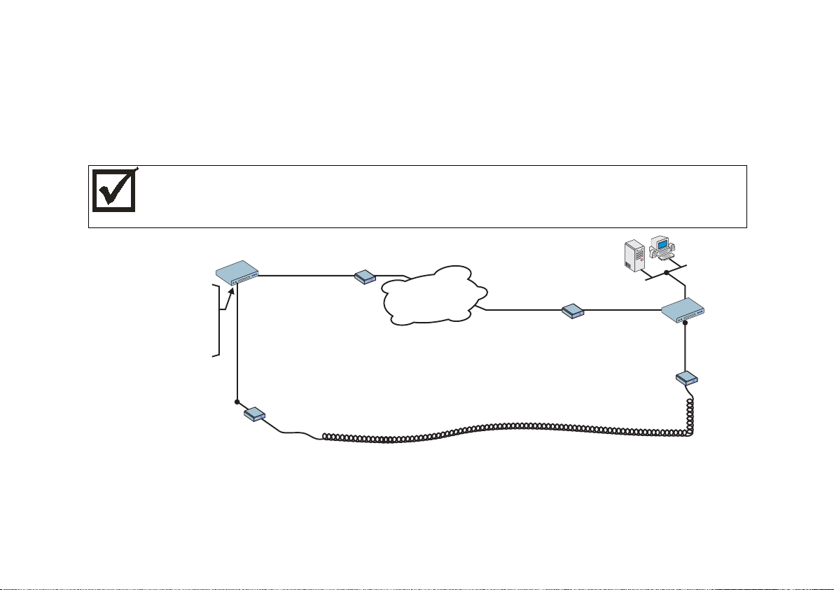
Example 3 Link Backup
This example shows the configuration of a backup link, with a swan connection to a public Frame Relay
Network providing the primary link and a SWAN with a PPP connection providing the secondary link. Figure
4.16 shows the networks used in this example. It is assumed that the routers are already connected to LANs
and that the SWAN interfaces have already been configured and are working. The use of a SWAN to connect
to a Frame Relay network is described in example 2 and a connection using PPP is shown in example 1.
Please read the entire example and follow the instructions before turning the router on. The router is
programmed to log the super user off after 10 minutes of inactivity. All data not explicitly saved to
memory is then lost. Collecting the data
configuring the router will likely cause delays and
while
frustration.
Network Address:
200.206.206.40
PR2000
SWAN 1
Modem or
DSU/CSU
_________
SWAN 2
IP Address:
100.200.200.1
________
Bandwidth: 64 kbps_____
Frame Relay
Network
Primary Link
Modem or
DSU/CSU
PR2000
IP Address:
100.200.200.2
________
Modem or
DSU/CSU
Modem or
PPP
DSU/CSU
Secondary (Backup) Link
Bandwidth: 64 kbps_____
FIGURE 4.16 PRIMARY AND SECONDARY (BACKUP) LINKS BETWEEN TWO LANS
Spaces have been provided next to the parameters needed for the configuration for you to fill in the parameters
for your system. Do this now before continuing.
35Chapter 4 - Step-by-Step Instructions
Page 36

Cyclades-PR2000
STEP ONE
The bandwidth used by CyROS for multilink circuit calculations is that given in the traffic control menu, rather
than the actual physical bandwidth available. If this bandwidth value is not set, the preset value (zero) will be
used and the multilink circuit will not function. The bandwidth for both links (SWAN 1 and SWAN 2 in the
example) should also have been set when the interface was configured. If not, the multilink circuit will not work.
Since the bandwidth was probably not set when the link was configured, you should make sure the value is the
desired one.
CONFIG=>INTERFACE=>SWAN 1=>T RAFFIC CONTROL=>GENERAL
Menu
Parameter Example Your Application
Bandwidth (bps) 64000
IP Traffic Control List None
CONFIG=>INTERFACE=>SWAN 2=>T RAFFIC CONTROL=>GENERAL
Menu
Parameter Example Your Application
Bandwidth (bps) 64000
IP Traffic Control List None
FIGURE 4.17 TRAFFIC CONTROL PARAMETERS
STEP TWO
Now, the primary link (Slot 1) and the secondary link (Slot 3) must be registered as a multilink circuit. First, a
multilink circuit is created and assigned an identifier. This is done in the CONFIG =>MULTILINK menu. Then,
the two links are added to the multilink circuit. The parameters used in the example for the two interfaces in
this multilink circuit are shown in Figures 4.18 and 4.19.
36Chapter 4 - Step-by-Step Instructions
Page 37

Cyclades-PR2000
CONFIG=>MULTILINK=>MULTILINK CIRCUIT NUMBER=>ADD/MODIFY INTERFACE
Menu
Parameter Example Your Application
Slot N SWAN 1
Type of Int e rf ace Main
Time to Activate
5
Backup After This
Link Goes Down
Time to Deactivate
20
Backup After This
Link Returns
FIGURE 4.18 ADDITION OF THE PRIMARY (MAIN) LINK
CONFIG=>MULTILINK=>MULTILINK CIRCUIT NUMBER=>ADD/MODIFY INTERFACE
Menu
Parameter Example Your Application
Slot N SWAN 2
Type of Int e rf ace Backup
Time to Activate
Backup After This
Link Goes Down
Time to Deactivate
, since this link IS the backup. (A
Zero
backup can itself have a backup, but
this is not done in this example.)
, since this link IS the backup.
Zero
Backup After This
Link Goes Up
Cost One. Indicates the relative priority of
this backup link, which is unnecessary
since this example has only one.
FIGURE 4.19 ADDITION OF THE SECONDARY (BACKUP) LINK
37Chapter 4 - Step-by-Step Instructions
Page 38

Cyclades-PR2000
STEP THREE
Up to this point, the configuration can be used either for link back up or for load back up. This example shows
link back up, but parameters applicable to load back up will be mentioned when they appear. Complete
information on the multilink circuit concept is provided in chapter 4 of the CyROS Reference Guide.
CONFIG=>MULTILINK=>MULTILINK CIRCUIT NUMBER=>CIRCUIT ATTRIBUTES
Menu
Parameter Example Your Application
Criterion for Traffic
Distribution
This parameter has no effect for link backup.
backup,
Optimal
distribution is performed randomly, and the
For load
packet is forwarded to the interface with the lesser load.
Address Based
distribution is used when the receiver cannot
reorder packets, and all packets to a certain IP address must
be sent through the same interface. This distribution method is
not recommended unless absolutely necessary.
Bandwidth Upper
Limit
for link backup. For load backup, this defines when load
Zero
backup should activate the backup link. It is measured as a
percentage of the bandwidth defined in step four.
Time to Activate
Backup if Above Limit
This parameter does not appear for link backup.
backup is activated after main link bandwidth exceeds limit
Time until
defined in last parameter.
Bandwidth Lower
Limit
This parameter has no effect for link backup.
backup, this defines when load backup should deactivate the
For load
backup link. It is measured as a percentage of the bandwidth
defined in step four.
Time to Deactivate
Backup if Below Limit
This parameter does not appear for link backup.
backup is deactivated after main link bandwidth exceeds limit
Time until
defined in last parameter.
FIGURE 4.20 MULTILINK CIRCUIT ATTRIBUTES
38Chapter 4 - Step-by-Step Instructions
Page 39

Cyclades-PR2000
STEP FOUR
Now, a static backup route must be created for the secondary link. It is assumed that a route of some sort
(static, RIP, etc.) already exists for the primary link. The static route parameters for the example secondary link
are shown in Figure 4.21. Fill in the parameters for your system.
CONFIG=>STATIC ROUTES=>IP=>ADD ROUTE
Menu
Parameter Example Your Application
Destination IP Address 200.206.206.0
Subnet Mask 255.255.255.0
Gateway or Interface Gateway
Gateway IP Address 100.200.200.2
Metric 1
Is This a Backup Route? Yes
OSPF Advertises This
Static Route
No, OSPF not used in this example.
If using OSPF, see chapter 12 of the
Installation Manual for guidance.
FIGURE 4.21 STATIC BACKUP ROUTE PARAMETERS
STEP FIVE
Now that the parameters have been defined, enter into each menu described above, in the order presented
(read chapter 3, Using Menus, if you have not done so already). Set the parameters in each menu according
to the values you wrote in the figures above. Save the configuration to flash memory at each step when
requested — configurations saved in run memory are erased when the router is turned off. If you saved part of
the configuration to run memory for some reason, save to flash memory now using the menu option ADMIN
=>WRITE CONFIGURATION =>TO FLASH. Be sure to change the superuser password using the menu
option CONFIG =>SECURITY => USERS =>MODIFY. The user ID, super, can remain the same, but the
password must be changed to avoid unauthorized access.
39Chapter 4 - Step-by-Step Instructions
Page 40

Cyclades-PR2000
STEP SIX
The multilink circuit can be tested by temporarily deactivating the interface on the primary link. This is done in
the ADMIN=> START/STOP INTERFACE menu by selecting the SWAN interface. If there is traffic, the backup
link should then take over, and the menu item INFO =>SHOW ROUTING TABLE will show that the backup link
is working. (To create traffic, try pinging a host in the destination network.) At this point, you should create a
backup of the configuration file (in binary) and print out a listing of the configuration.
Instructions for creating a backup of the configuration file:
Use the menu option ADMIN =>WRITE CONFIGURATION =>TO FTP SERVER. Fill in the IP address of the
computer where the configuration file should be saved, the file name, the directory name, and the user account
information. This configuration file can later be downloaded with the ADMIN =>LOAD CONFIGURATION
=>FTP SERVER option.
Instructions for listing the configuration:
The menu option INFO =>SHOW CONFIGURATION =>ALL will list to the terminal screen the configuration of
the router. This can be saved in a text file and/or printed on a printer.
40Chapter 4 - Step-by-Step Instructions
Page 41

Cyclades-PR2000
CHAPTER 5 CONFIGURATION OF THE ETHERNET INTERFACE
The PR2000 has one Ethernet 10Base-T interface, provided in a standard RJ-45 modular jack, which should be
connected to an Ethernet hub or switch. Use a standard 10Base-T straight-through cable (not included). When
the Ethernet link is correctly connected, the link LED will be lit. The menus for the Ethernet Interface are independent
of the speed of the link.
If your network uses 10Base2 (thin coaxial cable) or 10Base5 (thick coaxial cable), you will need a transceiver to
convert between the different Ethernet media. A crossover cable is required for direct connection to a computer
(an RJ-45 Ethernet pinout is provided in appendix B). Note: While Cyclades Power Routers work with most
standard RJ-45 cable/connectors, shielded Ethernet cables should be used to avoid interference with other
equipment .
The parameters in the encapsulation menu are preset at the factory and it is usually not necessary to change
them. The first step in the Ethernet configuration is to choose which network protocol to use and assign values to
the relevant parameters. Either IP, Transparent Bridge, or IPX (optional) must be activated. In this chapter, IP
Bridges are also described. Use the information provided below to set the parameters for the Ethernet interface.
The IP Network Protocol
Some parameters are explained in detail in later chapters. At this point, the preset values provided by the
operating system can be accepted and the interface will work at a basic level.
Network Protocol Menu CONFIG =>INTERFACE =>ETHERNET =>NETWORK PROTOCOL =>IP
Parameter Description
Active or Inactive Activates this interface.
Interface
Unnumbered interfaces are used for point-to-point connections.
Unnumbered
Assign IP From
Interface
Primary IP Address Applies to
Subnet Mask Applies to
Applies to
to this one.
Unnumbered
Numbered
Numbered
interfaces. Address assigned to this interface.
interfaces. Subnet mask of the network.
interfaces. Applies the IP address of another router interface
This table is continued.
Chapter 5 - Configuration of the Ethernet Interface 41
Page 42

Cyclades-PR2000
Network Protocol Menu (Continued)
Parameter Description
Secondary IP
Address
Applies to
Numbered
interfaces. Indicates a second (or third, etc. up to eight) IP
address that can be used to refer to this interface. This parameter and the next are
repeated until no value is entered.
Subnet Mask Applies to
Numbered
interfaces. Subnet mask of
Secondary IP Address
.
IP MTU Assigns the size of the Maximum Transmission Unit for the interface. This determines
whether or not a given IP datagram is fragmented.
NAT Determines the type of IP address if NAT is being used. Use
otherwise. See
Global
chapter 11 or the examples in chapter 2 for details on how to configure NAT.
ICMP Port
causes the router to send ICMP Port Unreachable messages when it receives
Active
UDP or TCP messages for ports that are not recognized. This type of message is
used by some traceroute applications, and if disabled, the router might not be identified
in the traceroute output. However, there are security and performance reasons to
leave this option
Inactive
.
Incoming Rule List Filter rule list for incoming packets. See chapter 12 for instructions on how this
parameter should be set.
Detailed Incomi ng IP
Accounting
Applies when a list is selected i n the pre vious parameter. See explanation of IP
Accounting in chapter 10. IP Accounting for a rule requires that the parameter
CONFIG =>RULES LIST=>IP=>CONFIGURE RULES=>ADD RULE=>ALLOW
Yes
.
Detailed
Outgoing Rule List
Name
Detailed Outgoing IP
Accounting
Routin g o f Broadcas t
Messages
ACCOUNT PROCESS also be
Filter rule list for outgoing packets. See chapter 12 for instructions on how this
parameter should be set.
Applies when a list is selected i n the pre vious parameter. See explanation of
Incoming IP Accounting
.
Activating this parameter causes the router to route broadcast messages from the LAN
to the WAN and vice-versa. An individual interface can be excluded by setting this
parameter to
Inactive
, without effecting the broadcast of messages on the other
interfaces.
Proxy ARP Causes the router to answer ARP requests with its own MAC address for IP addresses
reachable on another interface.
Chapter 5 - Configuration of the Ethernet Interface 42
Page 43

Cyclades-PR2000
IP Bridge
An IP Bridge is used to divide a network without subnetting. Whenever a subnetwork is created, two IP numbers
are lost — one describing the network and the other reserved for broadcast. This does not occur with an IP
Bridge.
200.240.240.9
200.240.240.3
200.240.240.2
200.240.240.1
ETH0
PR2000
Link 1
PR3000
.
.
.
.
.
.
.
.
.
.
.
.
.
.
.
.
.
.
.
.
.
.
.
.
.
.
.
.
.
.
.
.
.
.
ETH0
200.240.240.8
200.240.240.4
FIGURE 5.1 IP BRIDGE EXAMPLE
In Figure 5.1, an example of the use of an IP Bridge is given. From the available IP addresses, the range
200.240.240.4 to 200.240.240.8 is bridged to another physical location. The following parameters apply only for
IP Bridge.
Chapter 5 - Configuration of the Ethernet Interface 43
Page 44

Cyclades-PR2000
Network Protocol Menu (Continued) -- (IP Bridge)
Parameter Description
IP Bridge Activates the IP Bridge functionality.
The following parameters apply only if IP Bridge is
Initial IP Address to
be Bridged
Indicates the start of the range of IP addresses to be transferred to another physical
location. This and the next three parameters are repeated in case the bridge is to be
Active
.
broken up into various sections. Up to 8 sections can be defined. In the example, this
value is 200.240.240.4.
Ending IP Address to
be Bridged
Broadcast Over the
Indicates the end of the range of IP addresses to be transferred to another physical
location. In the example, this value is 200.240.240.8.
Allows propagation of broadcast IP packets over this bridge.
Link
Bridge Over Link Indicates which link forms the other half of the bridge. In the example, link 1 is used.
Other Parameters
Transparent Bridge is covered in chapter 7 and IPX is covered in chapter 13. The parameters defined in the
Routing Protocol and Traffic Control Menus should be set after reading chapters 9 and 12, respectively. It is
probably best to complete the basic configuration of all router interfaces, then return to the routing protocol and
traffic control menus after general routing and traffic control strategies have been defined.
Chapter 5 - Configuration of the Ethernet Interface 44
Page 45

Cyclades-PR2000
CHAPTER 6 THE SWAN AND ASYNC INTERFACES
This chapter describes how to configure a SWAN interface. The physical link should be set up as shown in
chapter 2, according to the type of modem or device at the other end of the connection and the type of SWAN
port. The async interface, provided on an RJ-45 connector, is the same as the SWAN interface except that the
synchronous option does not appear in the CONFIG =>INTERFACE =>SWAN =>PHYSICAL menu and the
only encapsulation option is PPP.
STEP ONE
The first step in the SWAN interface configuration is to define its physical characteristics. These parameters
are presented in the Physical Menu Table.
Physical Menu CONFIG=>INTERFACE=>SWAN=>PHYSICAL
Parameter Description
Mode Asynchronous or Synchronous. This parameter is determined by the mode of the
device at the other end of the connection.
Cloc k S ource Applie s fo r
Synchronous Mode
. Whether this interface provides clock for the device at
the other end of the cable or vice-versa. When the interface is connected to a modem,
the
Clock Source
Receive Clock Applies for
compare incoming messages with the clock it is generating (
it receives from the sender along with the message (
is always
External
Internal Clock Source
.
. When this interface provides clock, it can either
Internal
External
) or with the clock
).
Externa
l is
recommended.
Speed Applies for
Internal Clock Source
. Determines at which speed the data will be sent
across the line.
Media for SWAN
Cable
Type of cable -- RS-232, V.35 or X.21. Usually the type is cable is detected by the
router.
Chapter 6 - The SWAN and Async Interfaces 45
Page 46

Cyclades-PR2000
STEP TWO
The second step is to choose a data-link protocol in the Encapsulation Menu. There are many encapsulation
options on this interface.
For synchronous communication:
• Frame Relay: the Frame Relay Protocol is based on frame switching and constructs a permanent virtual
circuit (PVC) between two or more points.
• X.25: The X.25 Protocol is generally used to connect to a public network. The router can act either as a
DTE or a DCE.
• HDLC: A proprietary alternative to PPP.
For synchronous or asynchronous communication:
• PPP: The PPP (Point-to-Point) protocol is used for leased and dial-up lines. Multilink PPP is also
provided.
Information on how to determine the values of the parameters for each data-link protocol is provided in chapter
8.
STEP THREE
The third step is to set the Network Protocol parameters. Information for this step is provided in chapter 7.
Chapter 6 - The SWAN and Async Interfaces 46
Page 47

Cyclades-PR2000
STEP FOUR
If PPP Encapsulation is being used, a type of authentication should be chosen. This is done in the
authentication menu.
Authentication Menu CONFIG=>INTERFACE=>SWAN=>AUTHENTICATION
Parameter Description
Authentication Type
uses the list of users defined in CONFIG=> SECURITY=>USERS=>ADD.
Local
uses either Radius or Tacacs to authenticate the user.
Server
Remote
is when this interface is considered to be the user and the
other
end of the
connection performs the authentication
Username Applies when Authentication Type is Remote. The username the remote device
expects to receive.
Password Applies when Authentication Type is Remote. The password the remote device
expects to receive.
Authentication Server Applies when
Authentication Type
is
. Indicates that either a Radius or Tacacs
Server
server is used for validation. The location and othe r parameters of the server must be
configured in C ONFIG=> SECURITY. See section 4.3 of the CyROS Reference
Guide.
Authentication
Protocol
Applies when
Authentication Type
be used for authentication.
is
Local
or
. Either PAP or CHAP or both can
Server
STEP FIVE
The parameters defined in the Routing Protocol and Traffic Control Menus should be set after reading chapters
9 and 12, respectively. It is probably best to complete the basic configuration of all router interfaces, then
return to the routing protocol and traffic control menus after general routing and traffic control strategies have
been defined.
Chapter 6 - The SWAN and Async Interfaces 47
Page 48

Cyclades-PR2000
CHAPTER 7 NETWORK PROTOCOLS
The second step in most interface configurations is to choose which network protocol to use and assign values
to the relevant parameters. At least one of IP, Transparent Bridge, or IPX (optional, and discussed in chapter
13) must be activated. Use the information provided below to set the parameters for each interface. The
Ethernet network protocol menu includes IP bridging and is explained in chapter 5. The SWAN Network
Protocol Menu is given in figure 7.1. Note that this menu varies slightly for each interface. Specific information
on the options for each interface is provided in the CyROS Reference Guide in the chapter for the interface.
Config
Interface
SWAN
FIGURE 7.1 NETWORK PROTOCOL MENU TREE FOR THE SWAN INTERFACE
Chapter 7 Network Protocols
Network Protocol
IP
Transparent
Bridge
Active
Interface Unnumbered/Numbered
Assign IP from Interface
Primary IP address
Subnet Mask
Secondary IP Address
Subnet Mask
IP MTU
NAT
ICMP Port
Incoming Rule List Name
Detailed Incoming IP Accounting
Outgoing Rule List Name
Detailed Outgoing IP Accounting
Routing of Broadcast Messages
Status
Port Priority
Incoming Rule List Name
Outgoing Rule List Name
48
Page 49

Cyclades-PR2000
The IP Protocol
If the preset values provided by the operating system are accepted, the interface will work at a basic level. The
most common options are explained in the following table.
Network Protocol (IP) Menu CONFIG=>INTERFACE=><LINK>=>NETWORK PROTOCOL=>IP
Parameter Description
Active or Inactive Activates this interface.
Interface Unnumbered Unnumbered interfaces can be used for point-to-point connections.
Assign IP From Interface Applies to
Unnumbered
interfaces. Applies the IP address of an other router
interface to this one.
Primary IP Address Applies to
Subnet Mask Applies to
Secondary IP Address Applies to
Numbered
Numbered
Numbered
interfaces. Address assigned to this interface.
interfaces. Subnet mask of the network.
interfaces. Indicates a second (or third, etc. up to eight) IP
address that can be used to refer to this interface. This parameter and the next are
repeated until no value is entered.
Subnet Mask Applies to
Enable Dynamic Local IP
Address
The terminal connected through PAD assigns an IP address to the router for
purposes of their connection.
Numbered
interfaces. Subnet mask of
Secondary IP Address
.
Remote IP Address Type The computer connected through PAD or PPP sends its IP address in the
negotiation package.
: The IP address sent must match the number set in the next parameter.
Fixed
Same Net
: The IP address sent must be an address in the network set in the next
parameter.
: The IP address can be any number that does not conflict with any local IP
Any
address.
: Any IP address is accepted. This is not recommended.
None
Remote IP Address. If
Remote IP Address Type
not
. Used in conjunction with the previous
None
parameter.
this table is continued
Chapter 7 Network Protocols
49
Page 50

Cyclades-PR2000
Network Protocol (IP) Menu (Continued)
Parameter Description
IP MTU Assigns the size of the Maximum Transmission Unit for the interface. This
determines whether or not a given IP datagram is fragmented.
NAT Determi nes the type of IP address if NAT is being used. Use
Global
otherwise.
See chapter 13 or the examples in chapter 4 for details on how to configure NAT.
ICMP Port
causes the router to send ICMP Port Unreachable messages when it
Active
receives UDP or TCP messages for ports that are not recognized. This type of
message is used by some traceroute applications, and if disabled, the router might
not be identified in the traceroute output. However, there are security and
performance reasons to leave this option
Inactive
.
Incoming Rule List Filter rule list for incoming packets. See chapter 14 for instructions on how this
parameter should be set.
Detailed Incomi ng IP
Accounting
Applies when a list is selected i n the pre vious parameter. See explanation of IP
Accounting later in this chapter. IP Accounting for a rule requires that the
parameter CONFIG =>RULES LIST=>IP=>CONFIGURE RULES=>ADD RULE
=>ALLOW ACCOUNT PROCESS also be
Yes
.
Outgoing Rule List Name Filter rule list for outgoing packets. See chapter 14 for instructions on how this
parameter should be set.
Detailed Outgoing IP
Accounting
Routin g o f Broadcas t
Messages
Applies when a list is selected i n the pre vious parameter. See explanation of
Detailed Incoming IP Accounting
.
Activating this parameter causes the router to route broadcast messages from the
LAN to the WAN and vice-versa. An individual interface can be excluded by setting
this parameter to
Inactive
, without effecting the broadcast of messages on the other
interfaces.
Chapter 7 Network Protocols
50
Page 51

Cyclades-PR2000
The Transparent Bridge Protocol
The Transparent Bridge Protocol can be used in conjunction with either IP or IPX. A detailed explanation of its
use appears in section 4.6 of the CyROS Reference Guide.
Transparent Bridge Menu CONFIG=>INTERFACE=>SWAN=>NETWORK PROTOCOL=>TRANSPARENT
BRIDGE
Parameter Description
Status Activates the Transparent Bridge on thi s interface.
Port Priority For the Spanning Tree Algorithm, a priority is given to each link in the router and to
each router in the network. See CONFIG=>TRANSPARENT BRIDGE
=>SPANNING TREE in the CyROS Reference Guide for more information.
Incoming Rule List Name Trans parent Bridge rule list name for incoming packets. Note: Rule lists for
Transparent Bridge and IP are created separately. See section 4.7 in the CyROS
Reference Guide for instructions on how this rule list is created.
Outgoing Rule List Name Filter rule list name for outgoing packets. See section 4.7 in the CyROS Reference
Guide for instructions on how this rule list is created.
Chapter 7 Network Protocols
51
Page 52

Cyclades-PR2000
CHAPTER 8 DATA-LINK PROTOCOLS (ENCAPSULATION)
Each encapsulation option is presented in a separate section in this chapter. Not all data-link protocols are
available for all interfaces.
PPP (The Point-to-Point Protocol)
PPP is the only encapsulation option than can be either synchronous or asynchronous. It is important to choose
between them in CONFIG =>INTERFACE =><LINK> =>PHYSICAL before entering the Encapsulation menu.
The menu options depend on this choice. (Note: not all interfaces support both the synchronous and asynchronous
modes. In this case, there is no physical menu.)
The configuration of the PPP data-link protocol is confined to one menu, CONFIG =>INTERFACE =><LINK>
=>ENCAPSULATION =>PPP. Information about all the parameters appearing in this menu is provided in the
table below. Not all parameters will appear for all interfaces.
PPP Menu CONFIG =>INTERFACE =><LINK> =>ENCAPSULATION =>PPP
Parameter Description
MLPPP Enables Multilink PPP on this interface. MLPPP is described in the CyROS
Reference Guide for each interface that supports it.
Leased, Dial-in, etc. Applies for
Identification for This Bundle Applies for
Total Number of lines for
Applies for
MLPPP
MLPPP
MLPPP
=
. Type of line used on this link.
Yes
=
and
=
Yes
Yes
Dial-out
. Maximum number of links allowed in the bundle.
or
Leased
. An integer value.
This Bundle
PPP Inactivity Timeout Applies to asynchronous connections only. The connection is closed when data
does not pass through the line for this period of time.
Enable Van Jacobson IP
Header Compression
Allows the link to receive compressed packets. This type of compression is
useful for low-speed links and/or small packets. It is not recommended for fast
links, as it requires CPU time.
Transmit Compressed
Packets
Applies when
Enable Van Jacobson IP Header Compression
parameter causes the link to send compressed packets.
is
Yes
. This
Chapter 8 - Data-Link Protocols (Encapsulation) 52
Page 53

Cyclades-PR2000
PPP Menu (Continued)
Parameter Description
Disable LCP Ec ho
Requests
LCP (Link Control Protocol) messages are normally exchanged to monitor the status of
the link. Disabling these messages reduces traffic, but the link then has no way of
knowing if the other end is still connected.
Time Interval to Send
Config Requests
Config Request messages are used to negotiate the parameters at the start of a PPP
connection. For a slow line, this time should be increased to allow the reply to return
to the sender. If not, the sender will assume it was lost and send another.
Edit ACCM Applies to asynchronous connections only. Permits control character mapping
negotiation on asynchronous links. This is useful when you need to send a control
character as data (e.g. XON/XOFF, Crtl A, etc.) over an asynchronous link and do not
want it interpreted by the modem or other device in the middle. The map is built up
with the following commands.
– Resets the ACCM table toggle;
Clear
Toggle XON/XOFF
Toggle Char
– Add XON/XOFF control characters to the ACCM table;
– Add other control characters to the ACCM table, using their ASCII
value.
Typing the option once (for example, X), includes it in the table. Typing it again
excludes it from the table. More details are giv en in the CyROS Reference Guide.
Enable Predictor
Compression
Enables data compression using the Predictor algorithm. This feature should be
enabled only if Cyclades' equipment is being used on both ends of the connection
because there is no established standard for data compression interoperability. Data
compression is very CPU-intensive, making this feature effective only for links running
at speeds under 1Mbps. At higher speeds, the tim e necessary to compress data
offsets the gains in throughput achieved by data compression.
Number of Bits for
Compression
Connect ion Type Applies to as y n c hronous connections only.
Applies when
Predictor Compression Enabled
. Sixteen is fastest, but 10 must be used
if the router on the other end is a PathRouter, for compatibility.
NT- S e ria l Cable
is a direct connection to a
Windows NT computer. This is necessary because NT requires a negotiation before
the beginning of the PPP negotiation.
is used for other connections using
Direct
cables or leased lines.
53Chapter 8 - Data-Link Protocols (Encapsulation)
Page 54

Cyclades-PR2000
CHAR
The configuration of the CHAR data-link protocol is confined to one menu, CONFIG =>INTERFACE =><LINK>
=>ENCAPSULATION =>CHAR. Information about all the parameters appearing in this menu is provided in the
table below. Not all parameters will appear for all interfaces.
CHAR Encapsulation Menu CONFIG=>INTERFACE =><LINK>=>ENCAPSULATION =>CHAR
Parameter Description
Device Type Determ i nes whether a
port.
TCP Keep Alive Timer The delay between Keep Alive messages sent by TCP.
Terminal Type For a
Switch Sess i on
Character Code
Escape Session
Character Code
Username Applies for a
Wait for or Start a
Connection
Destination Hostname Applies for
Filter Null Char after CR
Char
Idle Timeout in Minutes Applies for
DTR ON Only if Socket
Connection Established
Device Attached to This
Port Will Send ECHO
terminal, ANSI
Applies for
2 is Ctrl-B, etc. The value 254 disables this option.
Applies for
return to the router menu without closing the session.
Terminal Device
Terminal Device
Terminal Device
chapter 16. If this parameter is left blank, the user will have to enter a username
Applies for
communication. When
is considered operational.
Socket Device
Socket Device
connected, if the previous parameter was start. This name must have been defined
in the host table. See chapter 16.
Applies for
connection, as CR (only).
Socket Device
Socket Device
Applies for
when the router is booted.
Applies for
chacters sent to it.
Socket Device
Socket Device
Terminal, Printer
is generally used. For a
. Control character used to switch sessions. 1 is Ctrl-A,
. Control character used while in a telnet session, to
. Must be entered into the local user table first. See
.
is used when the remote application will start the
Wait
is used, a connection is attempted as soon as the line
Start
. The remot e hostnam e t o whi ch the socket will be
. Interprets a CR NULL sequence, received on a TCP
. The connection is broken if no traffic passes in this time.
. If
False
.
if the device attached to the socket will echo the
Yes
, or
, the Data Terminal Ready line is switched on
device will be connected to this
Socket
printer, dumblp
is generally used.
Chapter 8 - Data-Link Protocols (Encapsulation) 54
Page 55

Cyclades-PR2000
PPPCHAR
The configuration of the PPPCHAR protocol is contained in the menu CONFIG =>INTERFACE =><LINK>
=>ENCAPSULATION =>PPPCHAR. The parameters for PPPCHAR are a combination of those for PPP and
CHAR. See the tables describing the PPP and CHAR options for guidance in configuring this protocol.
HDLC
This data-link protocol is a proprietary alternative to PPP. It has only one parameter, the
HDLC Keepalive Interval
This is the time interval between transmission of Keepalive messages. The receiver of these messages must
send keepalive messages with the same frequency or will be considered inoperative.
Frame Relay
FR supports multiple connections over a single link. Each data link connection (DLC) has a unique DLCI (data
link connection identifier). This allows multiple logical connections to be multiplexed over a single channel.
These are called Permanent Virtual Circuits (PVCs). The DLCI has only local significance and each end of the
logical connection assigns its own DLCI from the available local numbers.
Traffic Control based on Data Link Connection
Traffic Control as described in chapter 12 can also be performed on a Frame Relay interface for each permanent
virtual connection. The parameters in the
Add DLCI
menu are used in the same manner as those described in
chapter 12. More details are available in the CyROS Reference Guide.
.
STEP ONE
The first step is to set the general Frame Relay parameters, those applying to all DLCs. This is done in the Frame
Relay Menu. The parameters are shown in the table below. Most of these depend on the standards used by the
Frame Relay Network Provider.
55Chapter 8 - Data-Link Protocols (Encapsulation)
Page 56

Cyclades-PR2000
The Local Management Interface (LMI) Protocol provides services not available in simple Frame Relay . It is used
for controlling the connection between the user and the network. It monitors this link, maintains the list of DLCs,
and sends status messages about the PVCs. A separate virtual circuit is created to pass this information (DLCI
0).
Frame Relay Menu CONFIG=>INTERFACE=><LINK>=>ENCAPSULATION =>FRAME RELAY
Parameter Description
SNAP IP Indicates that the Sub-Network Access Protoc ol should be used. The router on the sending
end must be using the same header type (NLPID or SNAP) as the router on the receiving end.
See the CyROS Reference Guide for more information.
LMI Selects the Local Management Interface specification to be used.
(defined by the vendors that first implemented Frame Relay),
(used for a dedicated FR connection without a network).
None
ANSI, Group of Four
(defined by ITU -T), and
Q933a
T391 Interval between the LMI Status Enquiry messages.
N391 Full Status Polling Counter. Full Status Enquiry messages are sent every N391-th LMI Status
Enquiry message.
N392 Error Threshold. The network counts how many events occur withi n a given period and
considers an interface inactive when the number of events exceeds a threshold.
number of events to be considered and N392 the number of errors within this period. If
of the last
events are errors, the interface is deemed inactive. A successful event is the
N393
N393
is the
N392
receipt of a valid Status Enquiry message
N393 Monitored Events Count. See the description of
. This value must be larger than N392.
N392
CIR Committed Information Rate, in percentage of total bandwidth (bandwidth defined in
CONFIG=>INTERFACE=>SWAN =>TRAFFIC CO NTROL =>GENERAL =>BANDWIDTH).
Traffic a bove this rat e may be disca rded if the network is congested.
Bandwidth
Enables traffic control per DLCI. Traffic control options appear in the Add DLCI Menu.
Reservation
Chapter 8 - Data-Link Protocols (Encapsulation) 56
Page 57

Cyclades-PR2000
STEP TWO
After configuring the general parameters, each DLC must be defined. An example will be used to demonstrate the
procedure.
A public Frame Relay network connecting offices in São Paulo, Rio de Janeiro, Salvador , and Recife is shown in Figure
1 1.1. Each router will have a routing table pairing destination network with router interface and gateway . A Frame
Relay Address Map is also created (either statically or dynamically) to associate each DLCI with the destination
router IP.
For the router in Salvador, the Frame Relay address map will look like this:
DLCI IP
11 200.1.1.1
21 200.1.1.4
81 200.1.1.3
Data link connections are defined in the
Add DLCI
menu, which appears at the end of the Frame Relay parameter
list. It can be reached by passing through all parameters or by using the <ESC> key at any point in the parameter
list.
57Chapter 8 - Data-Link Protocols (Encapsulation)
Page 58

Cyclades-PR2000
São Paulo
Network: 192.168.200.0
Router
200.1.1.1
Rio de Janeiro
Network: 192.168.201.0
Router
200.1.1.4
21
11
81
200.1.1.2
Router
Salvador
Network: 192.168.203.0
200.1.1.3
Router
Recife
Network: 192.168.202.0
FIGURE 8.1 PERMANENT VIRTUAL CIRCUITS BETWEEN OFFICES
Chapter 8 - Data-Link Protocols (Encapsulation) 58
Page 59

Cyclades-PR2000
Add DLCI Menu CONFIG=>INTERFACE =><LINK> =>ENCAPS =>FRAME RELAY =>
<ESC>
=>ADD DLCI
Parameter Description
DLCI Number Used to identify the DLC. This number is supplied by the Public Frame Relay network
command.
L
maps the IP
Frame Relay Address
Map
provider. The DLCIs are stored in a table which can be seen with the
Determines the method used for mapping the remote IP address to the Permanent
Virtual Circuit.
maps one IP address to this DLCI.
Static
Inverse ARP
address dynamically, in a manner similar to the ARP table.
IP Address Applies when
Frame Relay Address Map
is
. Provides the IP address to be used
Static
for static address mapping.
Enable Predictor
Compression
Enables data compression using the Predictor algorithm. This feature should be
enabled only if Cyclades' equipment is being used on both ends of the connection
because there is no established standard for data compression interoperability. Data
compression is very CPU-intensive, making this feature effective only for links running
at speeds under 1Mbps. At higher speeds, the tim e necessary to compress data
offsets the gains in throughput achieved by data compression.
Number of Bits for
Compression
Applies when
Predictor Compression Enabled.
Sixteen is fastest, but 10 must be
used if the router on the other end is a PathRouter, for compatibility.
DLCI Priority Level This is the equivalent of CONFIG=>RULES LIST=>IP =>CONFIGURE RULES=>ADD
RULE=>FLOW PRIORITY LEVEL. See the section on traffic control in chapter 16.
Reserved Bandwidth This is the equivalent of CONFIG=>RULES LIST=>IP =>CONFIGURE RULES=>ADD
RULE=>RESERVED BANDWIDTH. Defines what percentage of the total bandwidth
on an interface will be set aside for this DLC. See t he section on traffic control in
chapter 16.
Bandwidth Priority
Level
This is the equivalent of CONFIG=>RULES LIST=>IP =>CONFIGURE RULES=>ADD
RULE=>BANDWIDTH PRIORITY LEVEL. See the section on traffic control in chapter
16.
To edit the DLCI table, use the list command (CONFIG=>INTERFACE=><LINK>=>ENCAPSULA TION
=>FRAME RELAY=>L) to discover the number CyROS has assigned to each table entry. It will not be the
same as the DLCI.
59Chapter 8 - Data-Link Protocols (Encapsulation)
Page 60
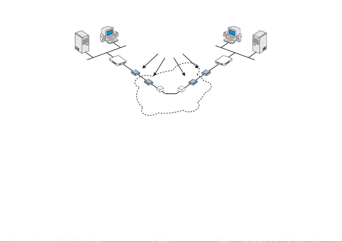
Cyclades-PR2000
Modem or
DSU/CSU
Router / DTE
Switch / DCE
Switch / DCE
Router / DTE
X.25
FIGURE 8.2 PUBLIC X.25 NETWORK EXAMPLE
X.25
A Cyclades Router can act either as a DTE (Data-terminal Equipment) connected to a public X.25 network or as
a DTE or DCE (Data circuit-terminating Equipment) as part of a private X.25 network. The first case is discussed
in this chapter. The second case is described in the CyROS Reference Guide. Both Permanent Virtual Circuits
(PVCs) and Switched Virtual Circuits (SVCs) can be defined. A PVC requires that two DTEs be permanently
connected.
STEP ONE
First, the general X.25 protocol parameters are set in the X.25 Menu. A detailed description of the X.25 parameters
and their values for the example is provided in the table below.
Chapter 8 - Data-Link Protocols (Encapsulation) 60
Page 61

Cyclades-PR2000
X.25 Menu CONFIG=>INTERFACE=><LINK>=>ENCAPSULATION =>X.25
Parameter Description
X.121 (Local DTE) Address Address assigned to this interface (provided by the public X.25 Network
Provider). Can be up to 15 digits.
Switch Mode Active Causes the Router to act as a switch.
Incoming Calls Received
Applies w he n S wit ch Mode is
Active
.
Over the Other X.25 Links
With Unknown Destination
DTE Can be Forwarded
Through This Link
Suppress Calling Address
Public X.25 Network:
This parameter must be chosen according to the
guidelines given by the Public X.25 Network provider. When activated, the
sender's Local DTE address is not included in the Call Request Message.
Inactivity Timeout Time until connection is automatically terminated by the router if there is no
traffic.
Configure as DTE or DCE As mentioned above, the router can act either as the recipient of information
), or as the passer-on of informati on (
(
DTE
DCE
).
Public X.25 Network:
Both
routers are DTEs.
Number of Virtual Circuits Indicates the maximum number of virtual circuits (total of PVCs and SVCs)
allowed on this interface. The maximum is 64.
Numbe r o f Pe rmanent
Virtual Circuits
Indicates the number of permanent virtual circuits that will be connected through
this interface. This maximum is also 64.
Layer 3 Window Size The layer 3 (packet) level window represents the number of sequentially
numbered packets that can be sent before an acknowledgement must be
received. This number may be negotiated if the Window Size Facility is utilized
(see last parameter in this table).
Layer 2 Window Size The layer 2 (frame) level window represents the number of sequentially
numbered frames that can be sent before an acknowledgement must be
received. The frame numbers are independent of the packet numbers.
this table continued
61Chapter 8 - Data-Link Protocols (Encapsulation)
Page 62

Cyclades-PR2000
X.25 Menu (Continued)
Parameter Description
Packet Size The packet size to be sent across the interface. This number ma y be negotiated
if the Packet Size Facility is utilized (see last parameter in this table).
Number of R e tries N2 Numb er of times a n informat i on frame ca n be r esent, without response, be fore
the link is c onsidered down.
TL Time the frame level waits for an acknowledgement for a given frame before re-
sending it.
T2 Time that can elapse, after receiving a frame, until the router must send an
acknowledgement.
T21 Call Request response Timer. After this time has elapsed, the DTE sends a
Clear message.
T23 Clear Request response Timer. After this time has elapsed, the DTE retransmits
the Clear message.
Negotiable Facilities Initiates facility negotiation during virtual cir cuit creation.
Send Facility Determines which facilities are negotiated during virtual circuit creation:
is part of the flow control parameters negotiation,
size
throughput class negotiation, and
N3 Window
(Level 3 Window Size, above) is
Throughput
Packet
is part of the
part of the flow control parameters negotiation.
Chapter 8 - Data-Link Protocols (Encapsulation) 62
Page 63

Cyclades-PR2000
STEP TWO
The next step is to create a static routing table associating each remote X.121 address with an IP address or a
TCP Socket location. This is done in the Add DTE menu, which appears at the end of the X.25 parameter list. It
can be reached by passing through all X.25 parameters or by using the <ESC> key at any point in the parameter
list.
X.25 Add DTE Menu CONFIG=>INTERFACE=><LINK>=>ENCAPSULATION =>X.25=>
<ESC>
=>Add DTE
Parameter Description
Type of Logical Address IP Address or TCP Socket. Users that intend to use the TCP Socket option should
see the CyR OS Reference Guide.
IP Address Applies for
IP Address Type
. IP Address of remote DTE device.
X.121(DTE) Address Address of remote DTE device.
VC Number Number assigned to this circuit, if it is a PVC. For SVCs, the value should be zero.
Enable Predictor
Compression
Applies for
IP Address Type
. Enables data compression using the Predictor
algorithm. This feature should be enabled only if Cyclades' equipment is being used
on both ends of the connection because there is no established standard for data
compression interoperability. Data compression is very CPU-intensive, making this
feature effective only for links running at speeds under 1Mbps. At higher speeds,
the time necessary to compress data offsets the gains in throughput achieved by
data compression.
Number of Bits for
Compression
Applies when
Predictor Compression Enabled
. Sixteen is fastest, but 10 must be
used if the router on the other end is a Cyclades PathRouter, for compatibility.
X.25 with PAD (Packet Assembler/Disassembler)
PAD acts as a protocol converter, allowing a user to access the packet-switched network via a serial terminal.
This asynchronous connection is then converted into synchronous communication with the router and the network
beyond (using the telnet application available in the router). Please see the CyROS Reference Guide for information
about this Encapsulation option.
63Chapter 8 - Data-Link Protocols (Encapsulation)
Page 64

Cyclades-PR2000
CHAPTER 9 ROUTING PROTOCOLS
Routing Strategies
Routing can be done either statically or dynamically.
Static Routing
Static routing is recommended when the network contains a small number of routers and other equipment. When
a system is simple and without redundant links, static routing is the simplest option. Even with some redundant
links, a multilink circuit can be created for semi-dynamic routing behavior. Multilink circuits are described in
section 4.4 of the CyROS Reference Guide.
Dynamic Routing
Dynamic routing is recommended when the network contains a large number or routers with redundant links
between them. RIP and OSPF are currently available in the Power Router line. RIP is simpler to configure and
is appropriate for systems that are stable (links do not go down often). OSPF is more complicated to configure,
requires much more CPU, and is not necessarily available in all equipment in a network. A mixture of RIP, OSPF,
and static routes is often used.
BGP-4 is a dynamic routing protocol used to route packets on the Internet. It is used in addition to the protocols
RIP and OSPF or static routing.
Chapter 9 - Routing Protocols 64
Page 65

Cyclades-PR2000
Static Routes
Routers used in very small or simple networks may use static routes as the primary routing method. When RIP or
OSPF are used, some static routes may still be needed. Configuration of static routes will be explained using two
examples.
Network 2
142.10.0.0
Mask: 255.255.0.0
D
142.10.0.2
C
142.10.0.3
142.10.0.4
Router 2
192.168.100.1
192.168.100.0
Mask: 255.255.255.0
142.10.0.1
10.0.0.0
Mask: 255.0.0.0
In the first example, three networks are connected by 2 routers. The routing table for router 1 will automatically
include servers A,B,C, and D, as they are direct links. A static route must be created for access to Network 3.
This type of route, a
be sent to Router 2. Details are given in the parameter table that follows.
Chapter 9 - Routing Protocols 65
Router 1
Gateway
10.0.0.3
192.168.100.2
E
10.0.0.2
B
10.0.0.1
A
FIGURE 9.1 STATIC ROUTING EXAMPLE 1
route, tells the router that any message not intended for hosts A, B, C or D should
Network 1
F
192.168.100.3
Network 3
Page 66
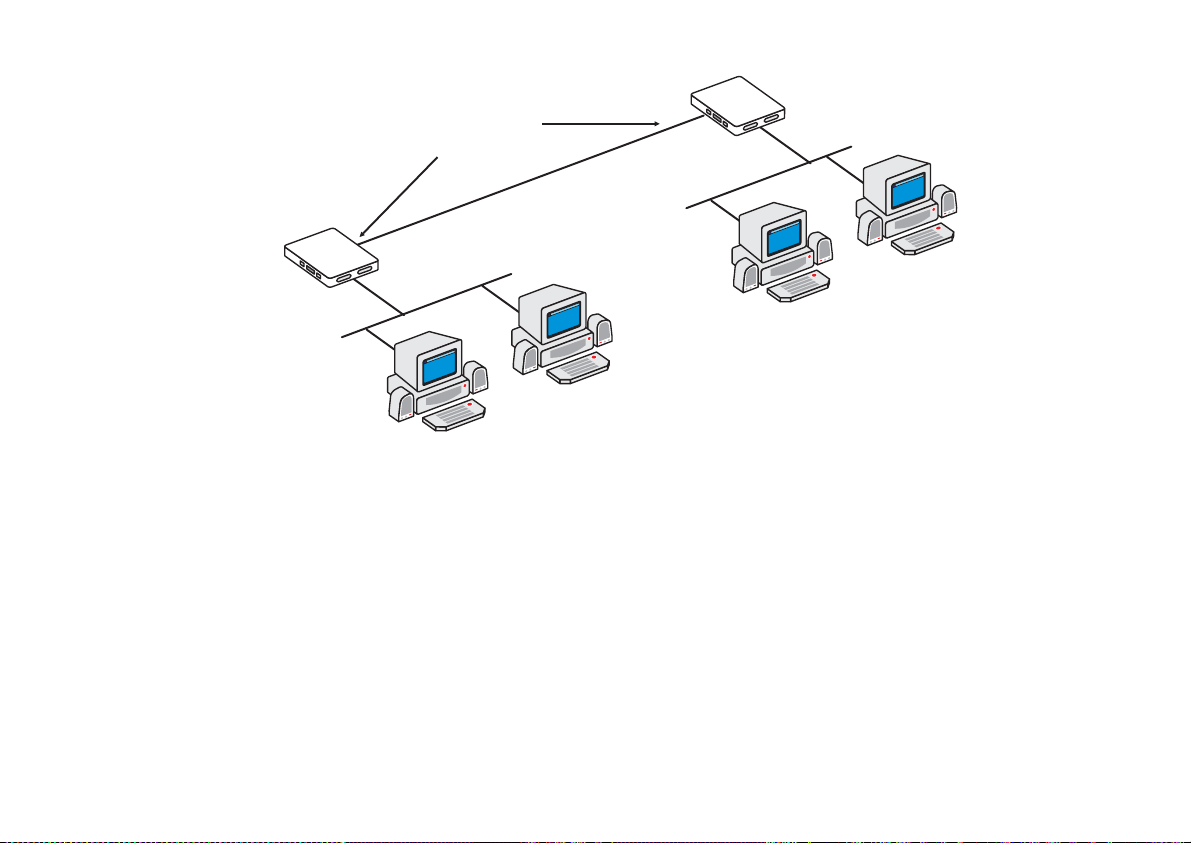
Cyclades-PR2000
Router 2
Router 1
ETH0
Unnumbered
Interfaces
Slot 1
10.0.0.3
Slot 3
Point-to-Point Connection
192.168.100.1
ETH0
E
F
Network 3
B
A
FIGURE 9.2 STATIC ROUTING EXAMPLE 2
Figure 9.2 shows another static routing example to explain the
routers is a point-to-point connection. Another network could be created, but is not necessary. Both routers can
be assigned unnumbered interfaces, because everything that leaves one router is sent to the other.
To define static routes, enter the menu CONFIG =>STATIC ROUTES =>IP =>ADD ROUTE. A description of the
parameters in this menu, with the configuration for Router 1 in the examples above, is given in the table that
follows.
Network 1
Gateway
or
Interface
parameter. Between the two
Chapter 9 - Routing Protocols 66
Page 67

Cyclades-PR2000
Add Static Route Menu CONFIG =>STATIC ROUTES =>IP =>ADD ROUTE
Parameter Description
Destination IP
Address
Address that route will lead to. To configure a default route, type "default" for this
parameter, otherwise enter 0.0.0.0 in both this and the next parameter.
Both Examples
-- for the static route between Router 1 and Network 3, the IP
addre s s is 19 2.168.100.0.
Subnet Mask
Gateway or Interface
Both Examples
Exampl e 1
Exampl e 2
-- To access all hosts in Network 3, its mask, 255.255.255.0, is used.
-- the route is to a gateway.
-- the route is to an interface since unnumbered interfaces are being
used.
Gateway IP Address Applies only when previous parameter is
the router. In
Example 1
, it is 142.10.0.4.
Interface Applies only when previous parameter is
N) that will be unnumbered. In
Example 2
Gateway
Interface
, it is Slot 1.
. It must be an address visible to
. Select the port (Ethernet or slot
Metric Relative cost of this link. Generally measured in number of routers between two IP
Is This a Backup
Route?
OSPF Advertises
This Static Route
addresses.
Indica tes that this route is used as a backup in a multilink circ uit. See section 4.4 for
more information about multilink circuits.
Static routes defined in the router can be advertised by OSPF. Both this parameter
and the parameter CONFIG=>IP=>OSPF=>GLOBAL=>ADVERTISE STATIC
Both Examples
ROUTES must be set to
External Metric Applies when
OSPF Advertises This Static Route
-- 1.
for the route to be advertised.
Yes
is set to
. Defines the metric
Yes
that will be advertised by OSPF.
External Metric-Type Applies when
OSPF Advertises This Static Route
is set to Yes. For
Type 1
, the total
metric of this route is composed of the internal metri c (inside the autonomous system)
and the external metric (provided in the previous paramet e r). For
Type 2
, the total
metric of this route is the value provided in the previous parameter.
Chapter 9 - Routing Protocols 67
Page 68

Cyclades-PR2000
RIP Configuration
CyROS supports three basic types of RIP:
1 RIP1 [RFC 1058]
2 RIP2 with broadcast (compatible with RIP1) [RFC 1723]
3 RIP2 with multicast [RFC 1723]
The primary difference between RIP1 and RIP2 is that only RIP2 advertises subnet masks and next hops. If the
network contains equipment that understands only RIP1 packets, then RIP1 or RIP2 with broadcast should be
used. See RFC 1723, item 3.3 for more details. If only RIP2 is used, RIP2 with multicast is recommended.
Unlike static routes RIP is configured on each interface rather than in a global menu. The menu is the same for all
interfaces and its parameters are presented in the table below.
RIP Menu CONFIG =>INTERFACE =>
<LINK>
=>ROUTING PROTOCOL =>RIP
Parameter Description
Send RIP Causes the router to transmit RIP messages.
Listen RIP Causes the router to accept RIP messages.
RIP2 Authentication Applies if
was chosen in the first two options. Activates RIP message
RIP2
authentication with a password.
RIP2 Authentication
Password
Chapter 9 - Routing Protocols 68
Applies if
RIP2 Authentication
transmitted RIP messages.
is
. Password used for both received and
Active
Page 69

Cyclades-PR2000
OSPF
The OSPF (Open Shortest Path First) routing protocol is significantly more complicated than RIP . The determination
of which protocol is better suited to a given network is beyond the scope of this manual. An example network
using OSPF is given in Figure 9.3.
AREA 1
Router 2
AREA 0
(Backbone)
Router 0
To Another
Autonomous System
Router 1
Link 1
Router 5
Router 3
Router 4
Router 6
AREA 2
AN AUTONOMOUS SYSTEM
Area Border
Routers:
R3, R6, R8
AS Boundary
Router: R5
Router 7
Virtual
Link
AREA 3
Router 8
Router 9
FIGURE 9.3 OSPF EXAMPLE
Chapter 9 - Routing Protocols 69
Page 70

Cyclades-PR2000
First, some definitions:
• An Autonomous System (AS) is a portion of the network that will use a single routing strategy . It is made up
of a backbone area and optionally of non-backbone areas.
• OSPF Areas are sub-systems that have identical routing databases. An area generally has no knowledge of
the routing databases of other areas.
• The Backbone connects areas and contains any routers not contained in another area.
• An Area Border Router connects areas and contains a separate database for each area it is contained in.
• An Autonomous System Boundary Router (ASBR) connects Autonomous Systems. The other Autonomous
System does not necessarily need to use OSPF.
STEP ONE
If using OSPF for the first time, sketch the network and determine which routers will make up the backbone and
each area. Determine if each router is an area border router or an autonomous system boundary router.
OSPF Configuration on the Interface
STEP TWO
Contrary to most other protocols in CyROS, OSPF must first be configured on each interface, then configured in
the CONFIG =>IP =>OSPF menu. Enter into each interface and set the parameters listed in the table.
OSPF Menu CONFIG =>INTERFACE =>
<LINK>
=>ROUTING PROTOCOL =>OSPF
Parameter Description
OSPF on This
Interface
Activates OSPF.
Enable Inactive
is used to temporarily disable the OSPF protocol
without erasing the parameters set below. This is useful when OSPF is first configured,
as the general parameters must be set afterwards in CONFIG=>IP =>OSPF and OSPF
cannot function without them.
Parameters that apply only when
Advertise This NonOSPF Interface
Causes the router to include this interface in its advertisements through other interfaces
(as an external route).
OSPF on This Interface
is
Disabled
.
This table is continued.
Chapter 9 - Routing Protocols 70
Page 71

Cyclades-PR2000
OSPF Menu (continued)
External Metric Defines the metric that will be advertised by OSPF.
External Metric Type For
, the total metric of this route is composed of the internal metric (inside the
Type 1
autonomous system) and the external metric (provided in the previous parameter). For
, the total metric of this route is the value provided in the previous parameter.
Type 2
Parameters that apply only when
OSPF on This Interface
is
Enable
or
Enable I na ctive
.
Area ID Identifies the area to which the interface belongs. Areas are created here, then later
defined in CONFIG=>IP=>OSPF =>AREA. Has the format of an IP address, but is not
linked to any IP address in the system. Small OSPF networks will typically have only
one area (the backb one area represent ed by 0.0.0.0).
Router Priority Priority used by OSPF in multicast networks to elect the designated router. A priority of
1 will make this router the most likely to be chosen. A priority of 2 will make it second
most likely. Set it to 0 (zero) if this router should never be the designated router.
Transit Delay in
Seconds
Estimated transit time in seconds to route a packet through this interface. Use the
preset value (1) or increase the number for slow links
Retransmit Interval * Time in seconds between link-state advertisement retransmissions for adjacencies
belonging to this interface.
Hello Interval * Time in seconds between the hello packets on this interface.
Dead Interval * Inactivity time (seconds) before a neighbor router is considered down.
Poll Interval * Time in seconds between the hello packets sent to an inactive, non-broadcast, multi-
access neighbor.
Password * String of up to 8 characters used to authenticate OSPF packages. The use of this
password is enabled in CONFIG=>IP=>OSPF=>AREA=>AUTHENTICATION TYPE
Metric Defines the cost for normal service. For consistent routing, this parameter should be
determined in the same manner for all routers in the OSPF Area. Normally, metric cost
is defined as an inverse function of interface throughput (e.g. 1 for 100Mbps, 10 for
10Mbps, 65 for T1, 1785 for 56kbps, etc).
Advertise Secondary
IP Address
Causes the router to advertise additional addresses assigned to this interface. These
are configured in CONFIG => INTERFACE =><LINK> =>NETWORK PROTOCOL =>IP.
* Inside a given area, these 4 parameters should be the same for all routers.
Chapter 9 - Routing Protocols 71
Page 72

Cyclades-PR2000
OSPF Global Configurations
STEP THREE
After completing the OSPF interface configuration for all interfaces (even those that will not use OSPF), navigate
to the OSPF Menu, CONFIG=>IP=>OSPF . Enter into the OSPF Global Commands menu and set the parameters
as indicated in the table below.
OSPF Global Commands Menu CONFIG =>IP =>OSPF =>GLOBAL
Parameter Description
OSPF Protocol Enables OSPF on all interfaces.
Router ID Assigns a unique ID to the router for use by the OSPF protocol. It must be one of the
router's IP addresses.
AS Boundary Router An Autonomous System Boundary Router (ASBR) can convert external routes into
OSPF routes. Which external routes is determined through the following parameters.
In the figure, only Router 5 is an ASBR.
The following parameters apply only to
Originate Default
Router will advertise itself as the Default Gateway (DG).
Autonomous System Boundary Routers
.
Gateway
Advertisement
Default Gateway
External Metric
Default Gateway
External Metric-Type
Applies when
Originate Default Gateway Advertisement
is set to
. Defines the
Yes
metric that will be advertised by OSPF.
Applies when
Originate Default Gateway Advertisement
is set to Yes. For
Type 1
total metric of this route is composed of the internal metric (inside the autonomous
system) and the external metric (provided in the previous parameter). For
Type 2
, the
, the
total metric of this route is the value provided in the previous parameter.
Advertise RIP Routes Routes learned through the RIP protocol will be converted to OSPF as external routes.
RIP External Metric Applies when
Advertise RIP routes
is set to
. Defines the metric that will be
Yes
advertised by OSPF.
This table is continued.
Chapter 9 - Routing Protocols 72
Page 73

Cyclades-PR2000
OSPF Global Commands (Continued)
Parameter Description
RIP External MetricType
Applies when
Advertise RIP routes
is set to
Yes
. For
, the total metric of this
Type 1
route is composed of the internal metric (inside the autonomous system) and the
external metric (provided in the previous parameter). For
, the total metric of
Type 2
this route is the value provided in the previous parameter.
Advertise Non-OSPF
interfaces
A router can have both OSPF and non-OSPF interfaces. This option causes the router
to advertise when these non-OSPF interfaces are up or down. When OSPF is
disabled on an interface, the parameter CONFIG=>INTERFACE =>
<LINK>
=>ROUTING PROTOCOL =>OSPF =>ADVERTISE THIS NON-OSPF INTERFACE
for the inte rf a ce to be advertised.
Yes
Advertise Static
Routes
must also be set to
Static routes defined in the router will be converted to OSPF. Note that static routes
can be configured individually as advertised or not in the parameter
CONFIG=>STATIC ROUTES=>IP=>ADD ROUTE=>OSPF ADVERTISES THIS
STATIC ROUTE. Both parameters must be
for the route to be advertised.
Yes
STEP FOUR
The next step is to define the areas created in step two. This is done in the OSPF Area Menu.
Area Menu CONFIG =>IP =>OSPF =>AREA
Parameter Description
Area ID Has the format of an IP address, but is not linked to any IP address in the system. Use
the CONFIG=>IP=>OSPF=>L option to see which areas have been defi ned, and use
the area ID here.
Authentication Type Simple password authentication can be used in OSPF. The authentication type should
be the same for all routers in an OSPF Area. If used, the password for each interface
is set in CONFIG=>INTERFACE=>
<INTERFACE>
=>ROUTING PROTOCOL =>OSPF
=>PASSWORD.
This table is continued.
Chapter 9 - Routing Protocols 73
Page 74

Cyclades-PR2000
Area Menu (continued)
Area Range N Status An Area Border Router (ABR) advertises link states for all networks within the area.
The number of such advertisements can potentially be reduced by condensing
different IP networks into a single range.
Area Range N Net
Address
Area Range N Mask Applies when
Applies when
Area Range N Status
is
Active
Sets the network IP address for the range.
Area Range N Status
is
Active
.
.
Sets the network IP mask for the range.
STEP FIVE
The CONFIG =>IP =>OSPF =>NEIGHBORS menu is required if the router uses OSPF over non-broadcast multiaccess interfaces such as X.25 and Frame Relay . If this is the case, set the parameters described in the following
table.
Neighbors Menu CONFIG=>IP =>OSPF =>NEIGHBORS
Parameter Description
Interface Link for which neighbors will be defined. In the OSPF example, consider link 1 of
Router 3.
Neighbor's IP The router ID of the neighboring router. For Router 3, link 1, use the router ID of router
1.
Neighbor's Stat us
includes link in OSPF database.
Enable
Enable Inactive
leaves link in OSPF database, but router at end of link (Router 1 in this
case) no longer passes OSPF information.
Disable
deactivates neighbor link and erases
Neighbor’s IP
.
Neighbor's Priority Priority used by OSPF in multicast networks to elect the designated router. A priority of
1 will make this router the most likely to be chosen. A priority of 2 will make it second
most likely. Set it to 0 (zero) if this router should never be the designated router. An
example can be seen in Area 1 in the figure -- Router 1 should never be the
Designated Router because it does not have a direct link to Router 2. Either Router 0
or Router 3 should be chosen.
Chapter 9 - Routing Protocols 74
Page 75

Cyclades-PR2000
STEP SIX
It is not always possible to connect all areas directly to the backbone. When an area is connected to the backbone
only through another area, two virtual links must be created. One from the backbone to the unattached area and
one from the unattached area to the backbone. If this occurs in the network containing the router, enter the Virtual
Links Menu to configure this link. In the table listing the parameters, the link between Area 3 (router 8) and the
backbone is used as an example.
Virtual Links Menu CONFIG =>IP =>OSPF =>VIRTUAL LINKS
Parameter Description
Transit Area ID ID of the OSPF Area sandwiched between this router an d the backbone. In the figure,
area 2 is the area used to link Router 8 with the Backbone. This ID has the form of an
IP ad d ress.
Neighbor's ID Router ID of router at end of virtual link. In the example, this will be Route r 6.
Virtual Link Status Activates the virtual link.
Parameters available only when
Transit Delay in
Seconds
Retransmit Interval in
Seconds*
Hello Interval in
Estimated transit time in seconds to route a packet from Router 8 to Router 6. Use the
preset value (1) or increase the number for slow links.
Time in seconds between link-state advertisement retransmissions for adjacencies
belonging to this interface.
Time in seconds between the hello packets on this interface.
Virtua l Link Status
is
Active
.
Seconds*
Dead interval in
Inactivity time (seconds) before a neighbor router is considered down.
Seconds*
Password* String of up to 8 characters used to authenticate OSPF packages. The use of this
password is enabled in CONFIG
=>IP=>OSPF=>AREA=>AUTHENTICATION TYPE.
* Inside a given area, these 4 parameters should be the same for all routers. In the example virtual link, they
should be the same as those used for the backbone.
Chapter 9 - Routing Protocols 75
Page 76

Cyclades-PR2000
BGP-4 Configuration
The BGP-4 routing protocol is used for routing on the Internet, performed between Autonomous Systems (ASs).
An autonomous system is defined as:
· A set of routers and networks under the same administration.
· An interconnected network, where no router is reachable solely through a path exterior to the AS
Each AS is identified by a 16-bit AS number. This number is supplied by the service provider.
Steps
1. Complete the Global Parameters
2. Register the neighbors of the autonomous system, the routers with which this router exchanges information.
At this point, the BGP-4 protocol is up and running. All remaining steps are fine tuning to improve performance
and reduce the size of the routing table.
If some routes that might be received are undesired, they can be filtered as they enter (or leave) so that they are
not placed in the routing table (or are not propagated to other autonomous systems).
This requires the following three steps:
3. Create an Access List
4. Add rules to the Access List
5. Return to the Neighbor configuration and match each list to the neighbor it should be applied to.
In some cases, a route should be accepted, but with changes determined by policies defined by the system
administrator. In this case, a route map should be created indicating which of the path attributes of the incoming
(or outgoing) message should be changed. This route map can be associated with a filter so that only specific
rules will be altered. The steps are the following:
6. Create a route map/sequence pair
7. Edit the neighbor definition to link it to the new route map
Chapter 9 - Routing Protocols 76
Page 77

Cyclades-PR2000
The last option is to aggregate the addresses contained in the local autonomous system in order to present an
aggregated route to the outside world. This is done in the last step.
8. Aggregate the addresses contained in the AS.
The steps defined above will now be clarified.
STEP ONE
The global parameters apply to the router’s AS. Classless Inter-Domain Routing (CIDR) Address notation is used
instead of the normal IP Address and Subnet mask notation. Both are shown in Figure 9.4.
AS 100
200.50.51.0
255.255.255.0
200.50.51.0 / 24
PR3000
..................................
100.100.100.1
100.100.100.2
200.200.200.1
AS 747
PR3000
..................................
Tele Popeye
200.50.50.0
255.255.255.0
200.50.50.0 / 24
AS 310
200.200.200.2
FIGURE 9.4 EXAMPLE SYSTEM WITH PR2000 IN AS 100 BEING CONFIGURED
Chapter 9 - Routing Protocols 77
PR3000
..................................
Tele Brutus
Page 78

Cyclades-PR2000
CONFIG=>IP=>BGP4=>GLOBAL
Parameter Description
BGP4 Protocol Activates the protocol.
Local AS Number This number is assigned by the service provider.
Router Identifier Usually the same as the Router ID, one of the interface IP addresses
Cluster Identifier Only used when this router is used as a router reflector.
Default Local
Value of the attribute "local pref" used by IBGP.
Preference
Accept Connections
From All Peers
Advertise Direct
Routes
Allows BGP connections from neighbors that have not been specified in the Neighbors
Menu.
Allows the removal of the interface routes from the list of routes to be advertised. In
the example these would be 100.100.100.1, 200.200.200.1 and the LAN interface IP
address.
Advertise Static
Allows the removal of static routes from the list of routes to be advertised.
Routes
Advertise RIP Routes Allows the removal of routes learned via RIP from the list of routes to be advertised.
Advertise OSPF
Allows the removal of routes learned via OSPF from the list of routes to be advertised.
Routes
The BGP network menu allows registration of the IP Addresses contained in the AS. This will mark these routes
as IGP instead of EGP or incomplete in the path origin attribute.
CONFIG=>IP=>BGP4=>BGP NETWORK=>ADD
Parameter Description
Network Address Network IP address of network to be added.
Network Mask (bitlen) Mask in CIDR format.
Chapter 9 - Routing Protocols 78
Page 79

Cyclades-PR2000
STEP TWO
The neighbor menu identifies the routers inside and outside the AS that will communicate with the router via BGP-
4. Each update message exchanged between routers contains path attributes. How these path attributes are
manipulated by the router when routes are received or sent to each neighbor is determined here.
CONFIG=>IP=>BGP4=>NEIGHBOR=>ADD
Parameter Description
Name A string to facilitate identification of the Neighbor. In the example above, the names
Popeye and Brutus could be used.
IP Address The IP address at the other end of the connection. For AS 747, the value is
100.100.100.2.
Description Another string to identify the Neighbor.
AS Number The AS number assigned to the neighbor.
Source IP Address When this number is set, the pro tocol accepts TCP/BGP connections only when the
destination IP is this value. For Popeye, the value would be 100.100.100.1.
Passive Causes the router to not initiate BGP connections with this neighbor.
Transparent-AS
causes the router to NOT include its own AS number in the "AS Path" path
Yes
attribute for update messages sent to this neighbor.
Transparent-NextHop
causes the router to NOT alter the "NextHop" path attribute for update messages
Yes
sent to this neighbor.
NextHop Self
causes the router to change the NextHop path attribute for update messages sent
Yes
to this neighbor. The value is replaced by the Source IP Address set above.
Route Reflector Client Indicates that this router is a route reflector and the neighbor is a route reflector client.
Weight Indicates the relative importance of the routes received from this neighbor. Routes
with greater weights are chosen over routes with lesser weights.
Maximum-Prefix When set, indicates the maximum number of routes that the router will accept in a
single update message from this router.
Holdtime When a message is not received from this neighbor for the holdtime, the neighbor is
considered inactive.
This table is continued.
Chapter 9 - Routing Protocols 79
Page 80

Cyclades-PR2000
CONFIG=>IP=>BGP4=>NEIGHBOR=>ADD (continued)
Keepalive Interval between keepalive messages sent to this neighbor.
Connection Retry
Time
When a connection with this neighbor is broken, the router try to reconnect with
frequency 1 divided by the Connection Retry Time.
Start Time Time delay before router tries to connect
Incoming Distribution
Applies a distribution access list to update messages received from this neighbor.
Access List Name
Outgoing Distribute
Applies a distribution access list to update messages sent to this neighbor.
Access List Name
Incoming Filter
Applies a filter access list to update messages received from this neighbor.
Access List Name
Outgoing Filter
Applies a filter access list to update messages sent to this neighbor.
Access List Name
Incoming Community
Applies a filter access list to update messages received from this neighbor.
Access List Name
Outgoing Community
Applies a filter access list to update messages sent to this neighbor.
Access List Name
Incoming Route Map
Applies a route map to update messages received from this neighbor.
Number
Outgoing Route Map
Applies a route map to update messages sent to this neighbor.
Number
Neighbor Alias
Additional address use d b y the other ro uter.
Address
STEP THREE
Figure 9.5 shows an example of a route that could be filtered out. The preferred route from 5 to 1 is through 4, with
6 serving as a reliable backup. Any route received from neighbor 2 which includes 5 will probably be a duplicate
of the equivalent route received from 4. In order to reduce the size of the routing table, all routes received from 2
than contain 5 can be filtered out of incoming update messages.
Chapter 9 - Routing Protocols 80
Page 81

Cyclades-PR2000
d
R
e
o
r
i
s
e
d
n
U
u
t
e
2
3
PR3000
1
.
.
.
.
.
.
.
.
.
.
.
.
.
.
.
.
.
.
.
.
.
.
.
.
.
.
.
.
.
.
.
.
.
.
B
a
4
P
r
e
f
e
6
c
k
u
p
o
r
r
u
t
R
e
d
e
5
100.10.0.0/16
e
t
u
o
R
FIGURE 9.5 MULTIPLE ROUTES CONTAINING AS 5
CONFIG=>IP=>BGP4=>ACCESS LIST=>ADD
Parameter Description
Access List Name Name assigned to list, to indicate which interface and direction it applies to.
Access List Type The AS Path type allows filtering by AS number; the Dist BGP type allows filtering by
IP address and the Community BGP type allows filtering by community. In the figure,
the filtering can be done based either on AS 5 or the address 100.10.0.0/16
Rule Status Enables the rule.
Default Scope If the default of the list is permit, the default of each rule must be deny and the
corresponding rule must define which routes must be discarded. If the default of the
list is deny, the default of each rule must be permit and the corresponding rule must
define which routes will be accepted (with all others being discarded).
Chapter 9 - Routing Protocols 81
Page 82

Cyclades-PR2000
STEP FOUR
An access list needs at least one rule. The example in Figure 9.6 shows three access lists, each one with several
rules. Each neighbor can be assigned up to 6 access lists, as seen in step 2.
Discarded
Routes
Discarded
Routes
Discarded
Routes
BGP-4
Message From
Seq. 10
Seq. 4
Seq. 2
Route Map
Rule 0
Rule 1
Access list
popeye_comm
type Community
Rule 2
Rule 0
Rule 1
Access list
popeye_dist
type Distribution
Rule 2
Rule 1
Rule 0
Access list
popeye_path
type AS Path
Tele Popeye
FIGURE 9.6 UPDATE MESSAGE ARRIVING FROM TELE POPEYE PASSING THROUGH 3 FILTERS AND A
ROUTE MAP
An update message arriving from the neighbor called Popeye in step 2 will pass through the filters assigned to it
in the Neighbor Menu. The figure shows the case where the scope of the list is permit and that of the rules is deny .
Each rule causes routes to be discarded until finally the shortened message arrives at the route map (if one has
been configured for this neighbor).
Chapter 9 - Routing Protocols 82
Page 83

Cyclades-PR2000
CONFIG=>IP=>BGP4=>ACCESS LIST=>CONFIGURE RULES=><ACCESS LIST NAME>
=>ADD
Parameter Description
Rule Status Enables the rule.
Scope See explanation of this parameter in step 3.
Rule AS Position Applies only for
Access List Type
equal to AS Path. Limits the search on AS number to
a particular position in the route. For the example in Figure 12.5, Any would be the
correct choice because AS 5 will appear in the middle or the beginning of the route.
Rule AS Number Applies only for
Access List Type
equal to AS Path. Applies the rule to routes
containing this AS number, with the restriction given in the preceding parameter.
Rule Distr. Search
Type
Rule Distr. Address Applies only for
Applies only for
Access List Type
IP Address/Mask pair exactly.
Access List Type
equal to Dist BGP.
matches more specific routes.
Refine
filters rules that match the
Exact
equal to Dist BGP. Applies the rule to routes with
this IP number and the mask defined in the next parameter.
Rule Distr. Mask
Bitlen
Community Applies only for
Applies only for
Access List Type
equal to Dist BGP. The shortened mask that is used
with the IP address defined in the previous parameter.
Access List Type
equal to
Community BGP
. Applies this rule to the
community number entered or to well-known communities defined in RFC 1997, BGP
Communities.
STEP FIVE
Each access list can be applied to more than one interface. The access list parameters in the Neighbor Menu for
the appropriate neighbor should be set now, since the access lists did not exist during step two.
Chapter 9 - Routing Protocols 83
Page 84

Cyclades-PR2000
STEP SIX
A route map can either apply to all routes not discarded by the access lists, as shown in Figure 9.6, or to routes
filtered by a particular access list, as shown in Figure 9.7.
Discarded
Routes
Discarded
Routes
BGP-4
Seq. 10
Rule 2
Seq. 4
Rule 0
Rule 1
Rule 0
Rule 1
Rule 0
Rule 2
Rule 1
Message From
Tele Popeye
Seq. 2
Access list
popeye_path
type AS Path
Access list
popeye_comm
type Community
Access list
popeye_dist
type Distribution
Route Map
FIGURE 9.7 ROUTE MAP ASSOCIATED WITH AN ACCESS LIST
In figure 9.7, the access list popeye_path is associated with sequence 2 of Route Map 1. Instead of the access list
causing the disposal of the routes that match its rules, it causes the application of the route map.
Chapter 9 - Routing Protocols 84
Page 85

Cyclades-PR2000
CONFIG=>IP=>BGP4=>ROUTE MAP=>ADD
Parameter Description
Route Map Number Identifies the route map
Sequence Number Identifies the sequence within the route map. The numbers need not be consecutive.
Match List Name Associates an access list with this sequence, as shown in the figure above.
Weight Alters the weight used to determine the best path. This value replaces the importance
assigned to the route by the weight parameter in the neighbor configuration.
Origin, Set Nexthop,
Set Metric, Set Local
These parameters modify the path attributes with the same name in the update
message.
Preference, Set
Atomic Aggregate,
Set Aggregate AS
number, Set AS Path,
AS Path Prepend,
AS Path AS-SET
STEP SEVEN
The neighbor definition should now be changed again to include the new route map. This is done in the Neighbor
Menu described in step 2.
STEP EIGHT
This last step permits aggregation of networks inside the AS to simplify routing tables. In the example in Figure
9.4, the two networks can be aggregated to form one network with the IP address/Mask of 200.50.50.0/23.
Chapter 9 - Routing Protocols 85
Page 86

Cyclades-PR2000
CONFIG=>IP=>BGP4=>AGGREGATE ADDRESSES=>ADD
Parameter Description
Number An ID f o r r eference.
Address The aggregated address. In the example, 200.50.50.0.
Mask (bitlen) The mask for the aggregated address. In the example, 23.
AS Set
cause s the route to be tagged with the AS Set path attribute. Otherwise, the AS
Yes
Sequence path attribute is assigned.
Summary Only Yes removes all more specific routes, leaving only the aggregated form. No maintains
both the individual and aggregated routes.
Chapter 9 - Routing Protocols 86
Page 87

Cyclades-PR2000
CHAPTER 10 CYROS, THE OPERATING SYSTEM
This chapter explains various operating system features that are not covered in other chapters:
• creation of the host table
• creation of user accounts and passwords
• IP Accounting
Creation of the host table
CyROS allows identification of hosts by name. In the menu CONFIG =>SYSTEM=>HOSTS, each host is
assigned a number (1 to 32), and a host name (a maximum of 8 characters). The IP address to be associated
with this host name and the port to be used for telnet is then requested. This host name can be used in
aplications like ping and telnet, and in some other configuration menus.
Another way to identify hosts by name is to configure access to a DNS Server. This is done in the menu
CONFIG =>IP =>DNS CLIENT. The domain name where the router is located and two DNS Server IP
addresses are the only parameters.
Creation of user accounts and passwords
Four users are preset:
1 super with the password surt,
2 usr with no password,
3 auto with no password, and
4 pppauto with no password
Chapter 10 - CyROS, the Operating System 87
Page 88

Cyclades-PR2000
Other users can be created and the user “usr” can be assigned a password. The password of the super user
should be changed as soon as possible. The menu CONFIG=>SECURITY=>USERS allows addition, deletion,
and modification of the list of users. The parameters are:
• User Name,
• Password,
• User Type: Super, Usr, Auto, or PPPAuto,
• User Status: Disabled or Enabled,
• Hosts 1 through 4 (the host names entered here must already exist in the host table).
• Automatic login name for hosts 1 through 4 (only for user of type
auto
)
Then the main menu items for this user are determined:
• Telnet,
• Ping,
• Traceroute,
• PPP,
• SLIP.
Lastly, any restrictions as to how the user may log in are defined:
• Console,
• Terminal,
• PPP Terminal,
• Telnet,
• PAD Terminal.
super
The
chosen in the user’s profile. The
The
Chapter 10 - CyROS, the Operating System 88
user has access to all menus. The
pppauto
auto
user is connected via telnet directly to the host specified as host 1 in the user profile. If an
usr
user is shown a menu, upon sucessful login, with the items
user is connected directly to the user via PPP. No menu appears.
automatic
Page 89

Cyclades-PR2000
login name
is indicated when the auto user is configured, the user is logged in to the remote host directly
(though a password may be necessary, depending on the remote host configuration).
IP Accounting
IP Accounting is used to count the total number of packets allowed (or not) to pass through an interface.
Statistics are given for packets that meet the criterions defined in a rule. (Traffic Rules are not supported). To
see all packets, a special rule list permitting everything can be defined. Rules are described in chapter 12.
Two versions of the IP account table are available for viewing. The result of INFO =>SHOW ACCOUNT TABLE
=>SUMMARY is shown below for four filter rules.
IP Accounting Table
Interface Direction Filter List Rule Bytes Packets
Ethernet Outgoing generic 0 24876 3072
Ethernet Incoming generic 0 49254 3358
slot 3 Outgoing swan3out 17 21362 3223
slot 3 Incoming swan3in 15 32563 3131
Detailed information can be accessed via SNMP.
To use IP Accounting, two parameters must be set. When a rule is created, the parameter CONFIG =>RULES
Yes
LIST =>IP =>CONFIGURE RULES =>ADD RULE =>ALLOW ACCOUNT PROCESS must be
. Additionally,
when applying a rule to an interface, the parameter CONFIG =>INTERFACE =>ETHERNET =>NETWORK
PROTOCOL =>IP =>DETAILED INCOMING /OUTGOING IP ACCOUNTING must also be Enabled.
Chapter 10 - CyROS, the Operating System 89
Page 90

Cyclades-PR2000
CHAPTER 11 NAT (NETWORK ADDRESS TRANSLATION)
NAT exists to convert local IP addresses into Internet “global” IP addresses. Internet IP addresses are
assigned by Internet providers. Due to the explosion of the internet, these numbers are scarce. Certain ranges
of IP addresses are reserved for internal use only — they may not have a direct connection to the Internet (for
reference, they are 10.0.0.0 - 10.255.255.255, 172.16.0.0 - 172.16.255.255, and 192.168.0.0 -
192.168.255.255). These are used as local IP addresses. Figure 11.1 shows an example of the utility of NAT:
Global Address Range
- Network: 200.240.230.224
- Mask: 255.255.255.240
ftp
Server
192.168.0.30
Networks
192.168.0.0 &
200.200.200.0
Host
Host
200.240.230.2
PR2000 With
Expanded NAT
200.200.200.11
200.200.200.10
PC
192.168.0.5
192.168.0.31
Router Ethernet Port
Primary IP Address: 192.168.0.1
Secondary IP Address: 200.200.200.1
FIGURE 11.1 NAT EXAMPLE
In this example, the company has:
• 14 global IP addresses available for NAT, 200.240.230.225 to 200.240.230.238,
• Two networks connected to the router via the Ethernet Interface, one of which will be translated,
• Two servers that are accessed via the same global IP address, assigned statically.
Chapter 11 - NAT
WWW
Server
90
Page 91

Cyclades-PR2000
There are two types of NAT available in CyROS -- Normal NAT and Expanded NAT. This chapter describes
Expanded NAT. A description of Normal NAT appears in Chapter 4 of the CyROS Reference Guide.
What is the difference between Expanded and Normal Mode NAT? The Normal Mode is a previous
implementation of NAT used in the Power Router line. It has been maintained for backward
compatibility. Expanded NAT provides static translation not only from one IP address to another, but
from one IP address/port pair to another IP address/port pair.
As a preview, after configuring the router as shown in the example, CONFIG =>SECURITY =>NAT =>L will
display:
NAT Enabled
NAT mode Expanded
Port map translation Enabled
UDP Timeout (min) 5
DNS Timeout (min) 1
TCP Timeout (min) 1440
TCP flags Timeout (min) 1
NAT Global Addresses
# address range
1 200.240.230.225 to 200.240.230.238
NAT Local Addresses
# address range
1 192.168.0.0 255.255.255.0 translated
Chapter 11 - NAT
91
Page 92

Cyclades-PR2000
NAT Static Translation Table
# Global address / port local address / Port Protocol
1 200.240.230.2 25 / 20 192.168.0.30 / 20 TPC
2 200.240.230.2 25 / 21 192.168.0.30 / 21 TPC
3 200.240.230.2 25 / 80 192.168.0.31 / 80 TPC
Types of Address Translation
In dynamic address translation, a pool of global IP addresses is loosely related to a pool of local IP
addresses. Mapping of one onto the other is done dynamically whenever a computer on the local network
requests a connection to the external network. When the connection is broken, the global IP address is
returned to the pool. Hosts connected via dynamic address translation must initiate all connections with the
external network.
In static address translation, one global IP address (or global IP address / port pair) is permanently associated with one local IP address (or global IP address / port pair). In the example, the web server is connected to
one of the global IP addresses for services on port 80, reducing the IP address pool to 13. Static address
translation is used when the connection with the external network is to be initiated from either side — external
or internal.
Translation may be done in two ways:
1 Address translation only – each global address is assigned to a single local address when necessary. In
the example, there are only 13 global addresses available and more than 13 hosts . With this type of
translation, only 13 servers can connect to the Internet at any given time.
2 Port and address translation — the UDP/TCP port and local IP address are translated as a pair. With this
type of translation, only ONE global address is needed. All hosts can be mapped to the same global IP
address. This can be used in our example to allow all hosts in the 192.168.0.0 network access to the
Internet at the same time.
Chapter 11 - NAT
92
Page 93

Cyclades-PR2000
An overview of the NAT menu is shown in the table below.
NAT Menu CONFIG =>SECURITY =>NAT
Menu Option Description
General Parameters for enabling NAT and choosing the NAT Mode. Also includes port
translation option.
Global Address The first and last IP addresses in the range. In the example, these numbers are
200.240.230.225 and 200.240.230.238.
Local Address The local network IP address and network mask, and whether or not the network should
be translated. In the example, these numbers are 192.168.0.0 and 255.255.255.0.
Static Translation Defines a static translation between a global IP address/port pair and a local IP
address/port pair. In the example, three such pairs are defined.
Timeout Definition of inactivity timeouts for UDP, DNS, and TCP dynamic NAT translations.
STEP ONE
The first step in the configuration of NAT is to enable NAT and choose the NAT Mode (Normal or Extended).
Only the extended mode is discussed in this chapter. The normal mode is a previous version of NAT
maintained for backwards compatability. See chapter 4 of the CyROS Reference Guide for information about
the Normal Mode.
NAT Menu CONFIG =>SECURITY =>NAT =>GENERAL
Menu Option Description
NAT Status Enables NAT.
NAT Mode Provides a choice between the previous NAT version (the
Normal Mode
) and the new
Extended NAT version.
Disable Port
Translation
Disabl e s/ enables N A T with port tr anslati on . I f t h i s p ar a meter is ch anged whi le t he router
is in use, al l t he ac t i ve transl at ions are d estroye d, a nd their en t r i es are removed from t he
translation table.
Chapter 11 - NAT
93
Page 94

Cyclades-PR2000
STEP TWO
The parameters in the Timeout Menu are explained in more detail below. The preset values should be
appropriate for most applications.
Timeout and Options Menu CONFIG =>SECURITY =>NAT =>TIMEOUT AND OPTIONS
Parameter Description
UDP Timeout Inactivity time required before a UDP translation is removed from the translation table.
An entry is created in the translation table the first time a UDP packet passes through the
interface. Five minutes is a reasonable time.
DNS Timeout Inactivity time required before a DNS translation is removed from the translation table.
TCP Timeout Inactivity time required before a TCP translation is removed from the translation table.
This time should be relatively long, because under normal conditions TCP connections
are formally disconnected with FIN (No more data from sender) or RST (Reset
Connection) flags.
TCP Flags Timeout Inactivity time required, after the receipt of a FIN, RST, or SYN (Synchronize sequence
numbers) flag, before a TCP translation is removed from the translation table. This time
can be relatively short, because after the TCP connection has been closed, there is no
furth er ne ed for its address translation.
STEP THREE
The next step is to define the global address range to which the local addresses will be translated. This is done
in the menu CONFIG =>SECURITY =>NAT =>GLOBAL ADDRESSES =>ADD RANGE. The
in the example in Figure 11.1 is 200.240.230.225, while the
Last IP Address
is 200.240.230.238.
First IP Address
The local address ranges must also be entered into the router in the menu CONFIG =>SECURITY =>NAT
=>LOCAL ADDRESSES =>ADD RANGE. Here, the Network IP Address (192.168.0.0 in the example) and
Network Mask (255.255.255.0 in the example) are entered. Since this range is to be translated, the parameter
Should This Range be Translated
translated. This can be configured by adding a new range and setting the translation parameter to
should be set to
Yes
. In the example, the network 200.200.200.0 is not to be
No
, or by
simply not adding the range.
Chapter 11 - NAT
94
Page 95

Cyclades-PR2000
STEP FOUR
If static translations are to be performed, as described in the example, the parameters in the Static Translation
Menu must be set. A brief explanation of each parameter is given in the table.
Static Translation Menu CONFIG =>SECURITY =>NAT =>STATIC TRANSLATION => ADD ENTRY
Parameter Description
Global IP Address One of the addresses assigned by the Internet access provider and included in one of
the NAT global address ranges.
Protocol TCP, UDP, ICMP, or any protocol.
Global Port The port to be translated on the WAN side. When a request comes in on port 80 for IP
200.240.230.225 in the example, it is sent to the server with IP 192.168.0.31, port 80
Local IP Address The IP address of the server (on the LAN, in the example) which is translated to an
Internet IP address.
Local Port The port to be translated on the LAN side. When a request comes in on port 80 for IP
200.240.230.225 in the example, it is sent to the server with IP 192.168.0.31, port 80.
STEP FIVE
After the NAT menu parameters have been set, the NAT property in the Network Protocol Menu of each
interface must be configured. In the example, the IP Address of the Ethernet interface is not assigned
dynamically. The parameter CONFIG =>INTERFACE =>ETHERNET =>NETWORK PROTOCOL =>IP=>NAT DYNAMIC ADDRESS ASSIGNMENT should be set to
Inactive
. The IP address of the interface connecting the
router to the Internet is also assigned by the super user in the example, rather than dynamically. The
parameter CONFIG =>INTERFACE =>SWAN =>NETWORK PROTOCOL =>IP=>NAT - DYNAMIC ADDRESS
ASSIGNMENT would also be set to
Inactive
.
After NAT has been configured and is running, the menu option INFO =>SHOW STATISTICS =>NAT will show
Network Address Translation Statistics.
Chapter 11 - NAT
95
Page 96

Cyclades-PR2000
CHAPTER 12 RULES AND FILTERS
There are four basic types of rules:
1 IP filter rules,
2 Radius rules (actually a combination of previously defined IP filter rules),
3 traffic control rules, and
4 transparent bridge rules (similar to IP filter rules, but for applications that use a transparent bridge).
IP filter rules and traffic control rules will be covered in detail in this chapter. See section 4.7 of the CyROS
Reference Guide for more information about all four types of rules.
As an introduction, the Rules List Menu Tree is presented in Figure 12.1. First, a rule list is created and
named. Second, rules are added to the list and defined.
Configuration of IP Filters
IP Filter rules are a very important part of a network’s firewall. They permit packets into or out of the network
depending on the source and destination IP addresses, the source and destination ports, the protocol used,
and the ACK bit for TCP packets. The Syslog can be used to monitor the packets that meet the rules applied in
this menu.
96Chapter 12 - Filters and Rules
Page 97

Cyclades-PR2000
Config
Rules List
IP
Add Rule List
Edit Rule List
Configure Rules
Same as Add
Rule List
Rule List Name
Add Rule
Delete Rule
Clear Rule List
Edit Rule
FIGURE 12.1 THE RULES LIST MENU TREE
Rule List Name
Rule Status
Rule List Type
Default Scope
Incoming Rule List Name
Outgoing Rule List Name
Linked Rule List Name N
Insert as Rule Number
Rule Status
Scope
Rule Priority Level
Reserved Bandwidth
Bandwidth Priority Level
Protocol
Source IP Operator
IP Address Start Mask
IP Address Start
IP Address End
Destination IP Operator
IP Address Start Mask
IP Address Start
IP Address End
Source Port Operator
Source Port Start
Source Port End
Destination Port Operator
Destination Port Start
Destination Port End
Allow TCP connections
Allow Account Process
Rule to delete
Same Parameters as Add Rule
Chapter 12 - Filters and Rules
97
Page 98

Cyclades-PR2000
Slot 1
192.168.0.2
Exterior Router
ETH0
192.168.0.1
Slot 1
Perimeter Network
192.168.0.0
Interior Router
Router
172.16.0.0
192.168.0.3
ETH0
Bastion
Host
10.0.0.0
Extension to Network
FIGURE 12.2 FIREWALL EXAMPLE
Figure 12.2 will be used to show how both an exterior router and an interior router would be configured using
the filters available in CyROS.
98Chapter 12 - Filters and Rules
Page 99

Cyclades-PR2000
t
Exterior Router
The exterior router is the network’s first defense against attacks. For this reason, it is reasonable to prohibit all
packets except for those explicitly allowed. This is done by choosing the
desired traffic must be expressly allowed by the rules in the rule list.
W
o
r
l
d
o
f
P
o
s
s
i
b
l
e
DENY
Let
e-mail out
Let
e-mail in
DENY
Default Scope
P
a
c
k
e
s
to be
Deny
. Thus, ALL
DENY
FIGURE 12.3 DENY AS DEFAULT SCOPE
Let Telnet
Connections Out
In Figure 12.3, a conceptual equivalent of the interface is shown. All packets except those which fall into the
holes in the ball will be denied entry in to or out of the network.
Chapter 12 - Filters and Rules
99
Page 100

Cyclades-PR2000
Steps necessary to activate filtering on the exterior router in the example:
1 There are two interfaces with two directions each. Filtering on link 1 requires the creation of two rule lists,
called exterior_in and exterior_out. Create them using the menu CONFIG =>RULES LIST =>IP
=>ADD RULE LIST and the following parameters:
Rule List Type = Filter
Default Scope = Deny
Linked Rule List Name = None
2 Create the rules for each rule list in the order in which they should be evaluated. The order is important
and mis-ordering the rules can cause unexpected results. This is done in the menu CONFIG =>RULES
LIST =>IP =>CONFIGURE RULES. The parameters for rules 0 and 1 in the example are shown in Figure
12.4.
3 Link the rule lists to the respective interface parameters in the menu CONFIG =>INTERFACE
<INTERFACE>
=>
=>NETWORK PROTOCOL =>INCOMING/ OUTGOING RULE LIST NAME. exterior_in
should be set as the incoming rule list name and exterior_out should be set as the outgoing rule list name.
Exterior_in, rule 0, allows a remote computer to connect to the bastion host using the TCP protocol on
its SMTP port. Exterior_out, rule 0, allows the Bastion Server to RESPOND to the connection started
out
by the remote computer. To send e-mail
, two more rules would be needed. If all the router needs to do is
receive e-mail, the configuration is done. If not, other “holes” must be created in the deny ball.
100Chapter 12 - Filters and Rules
 Loading...