

Page 1
THE “AVO”
VALVE CHARACTERISTIC METER
WORKING INSTRUCTIONS
THIRD EDITION
PUBLISHED B Y
THE AUTOMATIC COIL WINDER & ELECTRICAL EQUIPMENT CO. LTD.
WINDER HOUSE, DOUGLAS STREE T, LONDON, S.W.l
Telephone: Victoria 3404-9
Page 2
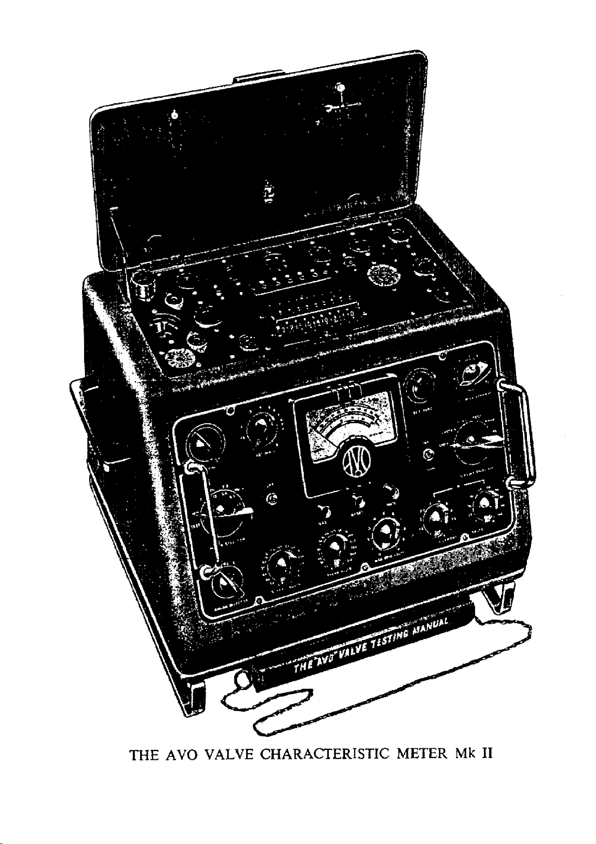
THE AVO VALVE CHARACTERISTIC METER Mk II
Page 3
F O R EWO R D
o r more than a quar ter of a century w e have be en engaged in the design and
manufacture of “AV O ” Electrical Mea surin g In struments. Throughout t hat tim e we
F
have consistently pio neer ed the design of modern multi-range instruments and have
kept abreast of and catered for the requir em ents of the e poch-makin g developments in
the fields of radio and electronics.
The success of our steadfast p olicy of main taining high st an dards of performanc e in
instruments of un excell ed accu rac y, and making such instruments avail able at rea sonable
cost, is reflected in the great respect and genu ine goodwill which “AVO ” pr od ucts enjoy
in every part of the World.
I t has been gra tifying t o note the very large number of instances where the satisfaction
obtaine d from t he perfor mance of one of our instruments has led to the aut omatic cho ice
of other instruments fro m the “AVO ” range. This process, ha ving continued ov er a long
period of years, has resulted in vir tual standardi sation on our products by numerous
Public Bodies, The Services, Railway Systems, and Pos t Office and Telegraph Undertaki ng s
throughout the worl d.
O ur design ers have thereby been encouraged to en sure that new instruments or
accessories for inclusion in the “AVO ” r ange fit in with existing “AVO ” apparatus and
serve to extend the usefulness of instruments already in use. Thus, the user who sta nda rdises
o n “AVO ” products will se ldom find h imself shor t of essential measuring equipment, for,
by means of s uitabl e accessories, his existing eq uipment ca n often be adapted to meet
unu sual demands .
It is with pleasure that we acknowledge that the unique po sition attained by “AVO ”
is due i n no small measure to the co-oper ation of so many users who stimula te our Research
and De velopment staffs from time to time wit h suggestions, criticisms, and even requests
fo r the pr od uction of ent irely new instrum ents or accessories. It is our desire to encou rage
and preserve this relationship between those who use “AVO ” I nstruments and those who
are respo nsible for th eir design a nd manufac ture, and correspondenc e is t herefore
welcomed, w hilst suggestions will receive prompt and sympathetic consideration.
3
Page 4

INDEX
For eword .. .. ..
Int rodu ction .............................................................
The Basic Method of characte ristic c h e c k in g
The Basic Method of checking diodes and re ctifie rs
Insulation Testing .. .. .. .. .: .. .. .. .. 8
T he Safety C ut-out.. ...................................................................................... 9
The Valve Panel and Selector S w itc h .......................................................................... 9
Pro cedure for setting up valve base connections .. ,, .. .. 10
Provision for new valve bases .......................................................................... 12
The prevent ion of Self oscillation of valves under test
Dia gram of Standard base pin conne ctions
Special pro cedure for valves ha ving internally connected pins .. . . . 14
The controls on the front panel, their functions and op erati ons
The Set 'v Control ...................................................................................... 16
The Electrod e Le aka ge S w itc h .......................................................................... 16
The Circuit Selector Switch .......................................................................... 16
T he Anode and Screen Voltage Switches
The Heater Voltage Switches .. .............................................................. 17
The N egative Grid Voltage Control .............................................................. 17
The Press Buttons ..
The Set Zero Control ...................................................................................... 17
The Meter Selector Switch...................................................................................... 18
The Set mA/V C o n tr o l ...................................................................................... 18
The Anode Selector S wit ch .......................................................................... 18
T he Sp ecial Ad ju stment Panel at the rea r o f the instrum ent .. .. . . .. 19
G eneral Procedure for testing a v a l v e .......................................................................... 19
Mains voltage adjustment and panel set up—cold and hot leakage tests—mutual
characteristic checks and gas tests—diode and rectifier tests made under load.
Instructions for test ing specific val ve ty pes .................................................. .. 22
Multiple diodes and rectifiers—double triodes and double pentodes—combined diode
and amplifying valves—frequency changers of heptode and hexode types—frequency
changers employing separate electrode assemblies.
The Use of the Link on th e Back P anel of the I nstr ument ..
Tuning Indica tors .. .. .. ...................................... .. . . 24
Gaseous Rectifiers .. .............................................................. .. .. 24
Cold Ca thode R ectifiers ...................................................................................... 24
Thyratrons .. .. .............................................................. .. ., 24
Neo n Indicators .. .. .. .. .. .. .. .. .. 25
General Precaution s to be obs erved when using the Valve Characterist ic Meter ., 25
N otes upon simple maintenance of instrument .. .. .. . . .. 26
Ci rcuit diagra m of Valve Ch ar acteristic M ete r
...................................... .......................... .. 3
.................................................
.................................................. 7
...................................... 7
...................................... 12
.......................... .. .. 13
.................................................. 17
.................................................
.......................... .......................... 27
..........................
...........................
..........................
5
15
17
24
The “ AVO Valve Data Manua l
This instrument will produce maximum information when used in conjunction with the Valve
Manufacturer’s Graphs and Technical Data, but to enable rapid checks to be made relative to a valve’s
general efficiency, the “ AVO” Valve Data Manual has been produced.
This instruction book refers throughout to the “AVO” Valve Data Manual, a copy of which should
always be kept with the instrument. New editions of this data manual will be published from time to time.
Watch our advertisements in the technical press for further announcements.
4
Page 5
Introduction
to
THE “AV O” VALV E CHARACTERISTIC METER
'T’he proble m of de signing a Valye Testing Instrument capable of giving a true and
A comprehensive pic ture of the state of any valve, has always been one of co nsiderable
magn itude, increasing in complexity as new valve types are brought into gen eral use.
For a quick general purpose test necessitating a minimum of time and technic al effort,
a mut ual conductan ce figure w ill give an adequ ate i dea of a valve’s usefulness, and the
original “AVO ” Valve Tester was design ed to tes t the efficiency of valves on t his basis.
Whilst a Valv e T ester must, of necessity, be accompani ed by a data book correlating
the results of the Tester wi th the cond ition of the valve in question, a purely empirical
figure, if u sed as a standard, will always give ri se to doubts in the mi nd of the operator.
Th e instrumen t should therefore , produce a figure which can be compared with so me
st andard quoted b y the valve ma nufactur er, if the opera tor is to use his in strument with
confidence. For this reas on the “A VO ” Valve Tester used the static ze ro bias mutual
conductanc e figure as a ba sis of comparison, this figu re being at that time almost universally
quoted by the valve manufacturer .
In order to reproduce this stan dard correctly, it was also nec essary to reproduce the
stated values of DC anode and screen voltage, a matter of some considerable difficulty
when it is realised that for an y stated condition of anode and/ or screen volts the correspond
ing electrod e currents can vary over very wide limits, and in the case of valves of low
initial a no de current a nd high slope, the actuation of the control w hich pro duc es the
milliamp-per-vol t reading might eas ily double the anode cu rrent flowing. With D.C.
methods of testing t he inherent internal resistanc e of the rectifying circu its use d could be
such as to give regulation errors wh ich c ould cause results to be meaningless unless com
plicated thermionic stabilising circuits and a vast array of monitoring meters were used
in all voltage supply circuits. Such complications would not only re nder the Tester of
prohibitive price and size, but would considerabl y increase the complication of ope ration
for the non-technic al user .
The problem was overcome by th e intr oduction of the AC method of ope ration (Patent
No. 480752) by which m ean s the nec essary DC test conditions were correctly simul ated
and a true mutual co nductan ce figu re produced b y the application of AC voltages of
suitable amplitude t o all electrodes. This e normously simplified the power supply problem,
rendered regulation er ror s n egligible , and obvia ted the necessity forvoltagecircuitmonitoring.
The “AVO ” Valve Tester thus fulfilled normal testing needs for a long pe riod. Du ring
recent years, however , electronic tec hniqu es have bec ome much more precise and the
natu re and mul tiplicity of valve types have contin uo usly incre ased. T he zero bias mutual
co nduct ance figure is seldo m quoted by the valve manufacturers, who, usually, publis h t he
optimum wo rking point mutual conductance and voltage figures, and in a large number
of cases give full fa milies of curv es, from which, precise operatio n, under a variety o f
working conditions, can be judge d. To cater for present day requireme nts therefore, a
valve testin g d evice should n ot only be capable o f producing a working point mutu al
conductance figure at any reasonable val ue of anode, screen or grid voltage r ecomme nded
by the manufacturers, but should also be cap able, if necessary, of reprodu cing any one
of the mutual characteristics associ ated with the valve i n qu estion. The instrument thus
has to simulate the performance of a compr ehensive valve mea surin g s et-up of laboratory
5
Page 6
Page 7
type and yet, at the sam e tim e, be sufficiently cheap and s imp le to ca ter for the needs of
the comparatively inexp erienced rad io test assistant. It is obvious that the very much
wid er application of an instrument of this class, would render the regulation difficulties,
already r eferred to, much mo re critical.
Investiga tions were, therefore, put in hand t o see whether th e AC test method would
reproduce DC conditi ons n ot only in respect of the mutual conductance figure taken at
a singl e disc rete poi nt, but at all points o n ail characteristi cs fr om zero bias to c ut off.
In other words, it was necessary t o de termine whether the general funct ion for a DC stati c
valve characteristic
(Va + ^ V gl + μ 2ν ?2)
la = f ---------------------------------
Ra.
would hol d when la was measured in terms of DC current, but wh en Va, Vg2 an d, if
necessary, Vgl, were replaced by 50 cycle AC voltage s of suitable magnit ud e. It was
eventu ally fou nd that a complete co-relation between the se two sets of conditions was h eld
when the grid voltage took the form of a sin usoidal wave form with the positive half cycle
suppressed (in other words , rectified but completely unsmoothed AC), and th e following
relationships were maintai ned :—
Va RMS — 1*1 Va in dicated DC
Vg.2 RMS = 1 ·! Vg3 ind icated DC
Vgx ( mean un smoothed) = 0*52 Vgj indicated DC
la (mean DC) = 0*5 ind icated la
From the above c onditions, therefore, the re quired relationship s were obtaine d which
fo rmed the basis of oper ation of th e Valve Characteristic Met er (Pat ent No. 606707).
Such an in strument, whilst retaining the advantages of simplicity, size and reas onable
price, res ultan t upon the elimination of complicated regulated DC supply systems and
univ ersal mon itoring, woul d have the inherent regu latio n easily ob tained from a well-
designed AC transformer. It would enable a valve to be c heck ed at any point on any one
of i ts many mutual characteristics and if necessary would allow a full family of character
istics to be drawn.
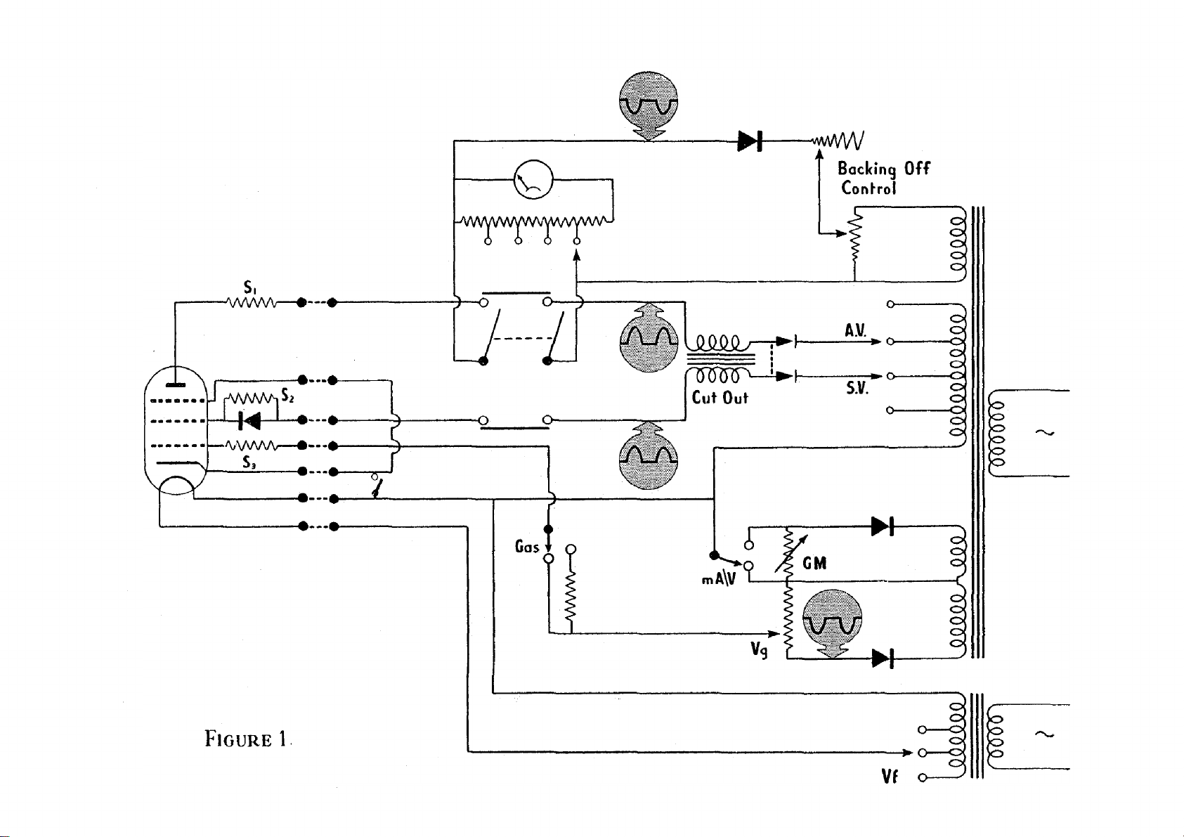
The basic method of characteristic checking
The fundamental circu it of operation of the instrument is shown in Figure 1 , the nature
of the wave forms present in the vario us parts of the circuit being indicate d thereon. As
in the origina l Valve Tester, the process of obtaining a direct readi ng mutual conductance
figure is simplified by the production of a backin g off circuit, whic h balances out the deflection
due to the standing anode current at the desired test condi tions prior t o the operation of
the mutual cond uctance button. Only the desire d figu re appears on the meter scale,
thus ena bling the meter to be set at a sufficiently sensitive range for preci se determ inati on
of mutual conductance. It will be noticed that the cu rrent flowing in this backing off
circuit is similar in wave form, but precisely opposite in direction to the an ode current,
thus eli minating any u nd esira ble rip ple that could otherwise bec ome appar ent when the
meter, after b acking off, was set to a sen sitive range.
The basic method of checking diodes and rectifiers
Any simp le emission te st at lo w applied voltage must necessarily give rise to a purely
em pirical figure for the valve in question which cannot necessar ily be co-r eiated wi th any
one of the maker’s characte ristics and w hich, owing to th e f act that it relates to the lower
bend portion of the rectifier characteristic may vary very w idely for any given type of valve.
7
Page 8
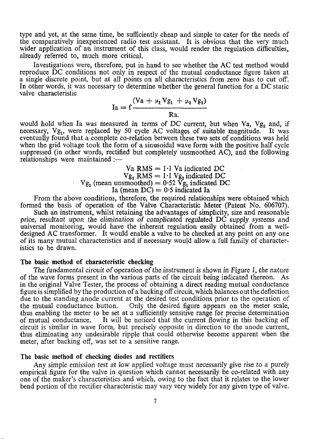
The important function of a rectifying valve is that it will, under suitable reservoir load
conditions, produce sufficient curr ent to operate the apparatus which it is intended to supply.
This fundamental requirement,' therefore, is the basis of rectifier testing in the Valve
Characteristic Meter. A sufficiently high AC voltage is applied to operate the valve above
the bend in its characteristic, and to ensure that its internal voltage drop is negligible.
With a suitable reservoir condenser in circuit, the DC load is adjusted to correspond to a
number of DC current conditions, i.e. 5mA, 15mA, 30mA, 60mA and 120mA. The actual
current flowing in the load circuit is then indicated on a met er shunted to correspond with
the DC load required. The meter read ing will then indicate as a percentage, the comparative
efficiency of the valve on the basis of this required DC load. Each half of a full wave
rectifying valve is tested sepa rately thus enabling matching of two halves to be checked
and any tendency to pr oduce hum by part ial h alf waving to be indicated.
The pre-det ermined lo ad figures are chosen so that they not only give a sufficiently
wide range o f c urrents to cater fox the no rmal requirements of electronic appara tus, bu t
also correspond to the DC maximum emission figures usually quoted by manufacture rs
in th eir rectifyin g valve data. Signal diod e valves are similarly tested, but a lower AC
voltage is applied and comp arison is mad e with a single DC load figure of 1mA, this figure
being normally more tha n sufficient to cover the rectified signal current that would be
obtained. The basic operating circuit of the diode and rectifier system is shown in Figure 2.
Insula tion Testing
To cover all eventualities, three distinct forms of insulation measurement are catered
for in the Valve Characteristic Meter. Measurements are taken with DC applie d voltages,
and direct indication of the insulation value in megohms is shown on the meter scale.
As an initial test, prior t o the application of operating voltages to the valve, th e rotation of
a switch enables the insulation figure to be shown, which occurs between ea ch of the valve
electrodes taken i n order and all the others strapped together. The denominat ion of the
Fi gure 2
Page 9
elect rodes between which any bre ak down exists will thus be autom atically indicated and
fu rther , the continuity of the heater circuit is shown as a zero resistance at th e heater (H)
positio n of the switch.
Wi th d irectly heated valves it is not un common for electro de sagging to occur on the
appl ication of heater voltage, with the result that a breakdown occurs between heater and
an adjacent electrode. To show up thi s condition a test circui t is provided indi cating the
insulation resistance betw een t he heate r and cathode of a valve and all oth er e lectro des
strapped when heate r v olta ge has bee n applied.
Fin ally the very important factor of heater to cathode insulation when the heater is
hot c an be tested , the insulation again being shown directly in megohms, the usual cat hode
to heater connection b eing ope ned for this purpose an d the appl ied voltage being in such
a direction as to make the cat hode negative with respect to the heater, thus avoiding false
indic ations of i ns ulation r esi stance due to el ect rode emission.
Safety Cut -O ut
To preven t dam ag e to in ternal components of the Valve Charac teristic Meter, due to
inadvert en t o r delib erate shorting of the sup ply voltages, a safety cut-o ut is incorp orated,
op erative when da maging overlo ads of AC current are taken fro m either t he anode or screen
voltage sources. The cut-out takes th e form of a two circuit polarised elect ro-m agne tic
relay which has two windings incorporated in its ele ctro-m agn etic system, one as sociated
with the screen vol tage supply and one with the anode voltage supply . It will be appr eciated
that with the valve electrodes taking normal curre nt, half wave DC pulses only will flow
through these windings and the dir ection and magnitude of the windings are such that with
anode cu rrent only flowing, or alternatively, with a c onsiderab ly larger anode curr ent than
screen current flowing, the cut-o ut will be held in contact and the inst rument will work
normally. It is obvious, however, tha t if an internal valve sho rt occurs on any one of its
high voltage electrodes, or alternati vel y, if such a short is a pplied externally via the valve
holder sockets, or other part of the circuit, or further if any int ernal short occurs as sociated
with t he ano de or screen supply circuits, th en the current flowing i n these circuits will not
ta ke the form of un i-dir ectional pulses, but will be ordinary AC curren t.
In such circumsta nces, the effect of the first ha lf cycle of AC current in the reverse
direc tion fro m no rma l w ill be such as throw out t he c ut-ou t and thus break both anode
and screen sup ply circu its. The overload is, th erefore, removed from the supply system
and bur n out of transformers and associate parts is obviated. Note t hat this protection
does n ot apply in the ca se of a sho rt applie d to the heater voltage windings as these norm ally
pass sinusoidal AC current . Further, if for any reason w hen te sting a pentode the anode
circ uit should become disconnected (this can occur when the rolle r sw itch is wrongly
set up) then the nor mal result would be for a dam agin gly heavy rectified cur rent t o flow
In t he screen circuit; the rel ative direction and magnitude of the two windings on the
cut-out is then such that w hen the current in the screen circu it seriously exceeds the cur rent
in the anode circuit the cut-out is t hr own and damage both to va lve and circuit is obviated.
It must be stressed that this cut-out will not operate upon the passage of normal heavy
currents o f a DC nature occurring in the valve anode circuit, and it will not protect the
movement if the latter is wrongly set on a range not corresponding to the current passing.
This problem is dealt with by ensuring that the movement is always set to its maximum
current range when the probable magnitude of the current is unknown.
THE VALVE PAN EL AN D SELEC TOR S WITCH
The Valve Pane l com prises 18 valve holders of the fo llow ing types :—English—4/5
pin, 7 and 9 pin, 8 pin side contact, B7G. B8 A, B8B ( American Loc tal), B9G, Englis h Octal,
9
Page 10

B3G, 4 and 5 pin Hiv ac : A merican—4, 5,6 a nd sma ll 7 pin UX, m edium 7 pin UX, Octal,
and B9A. Provision is made by means of plug-in adaptors to cater for newly introduced
valve bases. These valve holders are all wired with th ei r corr esponding pins, ac cor din g
to the st andard pin numbering, in parallel, i.e. a ll pins n umb er one are wired togethe r, all
pins number two, and so on. T his wiring combination is associated with the well-k nown
“AVO ” Multi-Way Selector Switch whic h enables any one of the nine standa rd pin nu mbers
to be connect ed to any one of th e elect rode tes t circuits in t he Valve Characteristic M eter
pr op er, thus enabling any electrode combination to be set up for any n orma l valve hol der.
It will b e seen that the Selector Switch comprises nine thumb control r ollers, numb ered
from left to right 1— 9. This numberi ng a ppears on the moulded escutcheon immediately
behind t he rollers and corresp on ds to the valve pins in the order of their stan dard pin
numb ering. Thus valves with any number of base c onnections up t o nine c an be accom
modated. Further, to accommodate top cap and other external valve conne ctions a socket
panel is provide d wit h five sockets marked G l, S, A l, A2, D1 the markings corresponding
to the valve el ectrode conn ec tion which is made externally to the valve.
Rotat ion of the rollers by the fin ger rim provided will re veal that eac h roller can be
set in any one of ten positions, the setting in qu estion being indica ted in the window op ening
at the front of the e scu tcheon . The t en posi tio ns on the roller a re marked as under:—
1 2 3 4 5 6 7890
C Η - H + G S A A2 D1 D2 E
Th e numbers are provided for ease of memorising and noting base combin ations,
but the corresponding electrode denomin ations are shown by the l ett er ap pearing in the
escutcheon window immediat ely underneath the number, t hu s :—
corresponds to C athode.
(1)
(2)
C
H—
„ „ Heater normally Earthy, or conn ected to nega tive L.T.
in the case of a battery valve.
(3)
(4)
(5)
(6)
H4-
G
S
A
„ the other Heater connection or centre tap.
„ „ Control Grid.
„ „ Screen Grid or g2.
„ „ normal anode of single or multiple valve. I n the case of
an O scillat or mix er valve, A repre sents the Oscillator
anode.
(7)
A2
„ „ second anode of double valves, and in the case of
Os cillator mixer valves, the mixer anode.
(8)
D1
„ „ the first diode anode of ha lf and full wave signal diode
and rectifier valves , diode and rectifier/ampl ifier
co mbinati on s.
(9)
D2
„ „ the second diode an ode of signal diode and rectifier
valves, diode and rectifier/amplifier combination s.
(0)
E
„ „ any earthed screen or screening electrod e not operating
und er applied voltage conditions nor normally connected
to cathod e.
Procedure for setting up valve base connections
The standard procedu re for s etting up a valve rea dy for test is as follows. From some
suitablesourc ei.e.“AVO” Valv eData Manual,Valve Manufacturer's Data Le aflet or publis hed
man ual of Valve Data, d etermin e the pin basing connections for the valve, in order of
thei r standa rd pin numberin g. Rota te the rollers of the Sel ector Switch until the set up
number or electrode letter combination appears in the window read ing from left to righ t
in order of the standa rd pin n umbering. I n the cas e of valves having less than nin e pins,
the fre e roll ers on the righ t o f the set up combinations correspo ndin g to non -existent valve
10
Page 11

electrode s should be set at 0(E) . Insert the valve in t he appropriat e valve holder. With
on e of the leads provided connec t any top cap or side connection on the valve to its
appropriat ely marked so cket, on th e Socket Panel immediat ely above t he Selector Switch.
Note that th e loctal valve holder having only eight normal ele ctrode s has its centre lug
connected to the n inth roller (correspo nding to pin No. 9) to accommodate valves which
have a cathode connection made to this lug.
The accompanying example s show how to co-relate the pin basing data and th e
equivalent set-up combination for a number of valves in common use.
Valve Type Set up Number Base Diagram
1. Osram MH4 in directly 6 4 2 3 10000
heated triode. A G H—- H-j- C E E E E
British 5-pin base.
2. Osram U50 full wave 0 2 080903 0
rectifier dire ctly heated. E H — E D1 E D 2 E H + E
Octal base.
3. Mullar d PenA 4 indir ect
ly he ate d output pen
0452 3 1600
E G S Η— H+ C A E E
tode .
British 7 pi n base.
4. American 6K8 indirec t
ly heated freque ncy
2
E
H-
7 5
A2 S
4 6 3 1
G A H + C
0
changer.
Octal base.
Top Cap Gl.
5. Mullard TDD2A b attery 6 8 2 3 90000
double diode triode. A D1 Η— H + D2 E E E E
British 5-pin base. Top Cap Gl.
6. Mullar d EF50 indirect- 2 5 6 1 0 1 4 0 3
ly heate d HF pentode. H— S AG3ECGEH4-
B9G base.
11
Page 12

Provision for New Valve Bases
To cover t he possibility of the introduction of new valve bases not provided for on the
standard panel and also the introduction of valves which may necessitate special conditions
asso ciated with standard valve holders, a plug- in adaptor is available which enables any
non-standard valve holder to be combine d in this adaptor and plugged int o the octal or
other suitab le base on the Valve Characteristic Panel . These a daptors are available
fo r bases not included on the Valve Pan el, and a lso w ith a blank valve holder m ounting
panel i n which can be mounted the user’s own valve h older if he require s any special
arrangement for which we have not catered.
The Prevention of Self Oscillation of valves under test
It will be realised that the length of wiring and its assoc iated capacity, co nnected
to t he grid and anode pins o f any one of the valve holders, ca n con stit ute a tun ed
line corres ponding to a high r esona nt frequency often of th e orde r of 100 megacycles per
seco nd or higher. A number of modern valves have sufficiently high slope to ove rcome
the inherent losses associated with su ch a tu ned line, and are, therefore, capable of bursting
int o os cillation at a frequency determined by the constants of their associated valve hold er
wiring when being tes ted at or near t hei r max imum wo rking slope. It is quite obvious
that in or der to test a valve some wirin g must exist between the valve holder and test
circuit. F urther, since a multiple test panel is desirable to obviate the necessity of a vast
numbe r of separate plu g-in units, the total amount of wiring asso ciated wit h any one valve
ho lder must be a considerable number of inches in length. It is almost impossible
to increase the effective resona nt frequency of the lines thus produced to such a high value
that no normal valve will oscil late therewith. The only altern ative is to render the line of
comparatively high loss a nd in extreme cases to st opper the valve in question righ t on top
of its anode and/or grid con nection. Unfo rtunately, however, since a very large n umbe r
of pin combinations have to be accommodated in any one valve holder the pres ence of
such a r esistan ce in say a heater or cathode ci rcuit could give complet ely erroneous results,
and this stopp ering system could there for e only be very sparsely used.
In c ertain circ umstances where a newly introduce d valve of high efficiency is likely
to be tested in any qua ntity and shows signs of oscil lation, the sepa rate valve hol der ada ptor
can be employed with considerabl e advantage . By this means a valve holder c an be
stoppe red to the maximu m ext ent necessary for the valve in question wit hout reference
to any ot her valves that may be incorporated therei n, as when the other types of valves
are likely to be used, the adaptor can be set a side and the valv e panel used normally. It
must be stressed that this oscillation is unlikely to occur where th e valve is teste d at anode
currents lower tha n normal, or at a point on its cu rve wh ich renders its mutual conductance
low. Were a purely empirical method of te sting employed in the Valve Characteristic
Meter, there fore, the proble m wrould in all probability not arise, but since every effort
has been made to actually test the valve under its correct operating conditions of current
and voltage, then it is on this account working at its normal efficiency and can, unless
special prec auti ons a re taken, give r ise to the oscillation trouble s to which we have
referred.
Whi lst discussing the prob lem of oscillation, mention should be made of the rectifier
(which will be seen in the circuit diagram) included in the screen circui t of pentode and
tetrode valves. This rectifier ha s been incorpor ated to obviate a difficulty which can a rise
in certain c ircumst ances when testi ng valves of the beam ^etrode type with a lternating
current app lied to their electrodes. A s the applied ele ctrode voltages approach ze ro
during a portion of their operativ e cycle, the focusing of the beam of such valves is to
some extent up set and the result can be that the screen circ uit begins to show an
12
Page 13

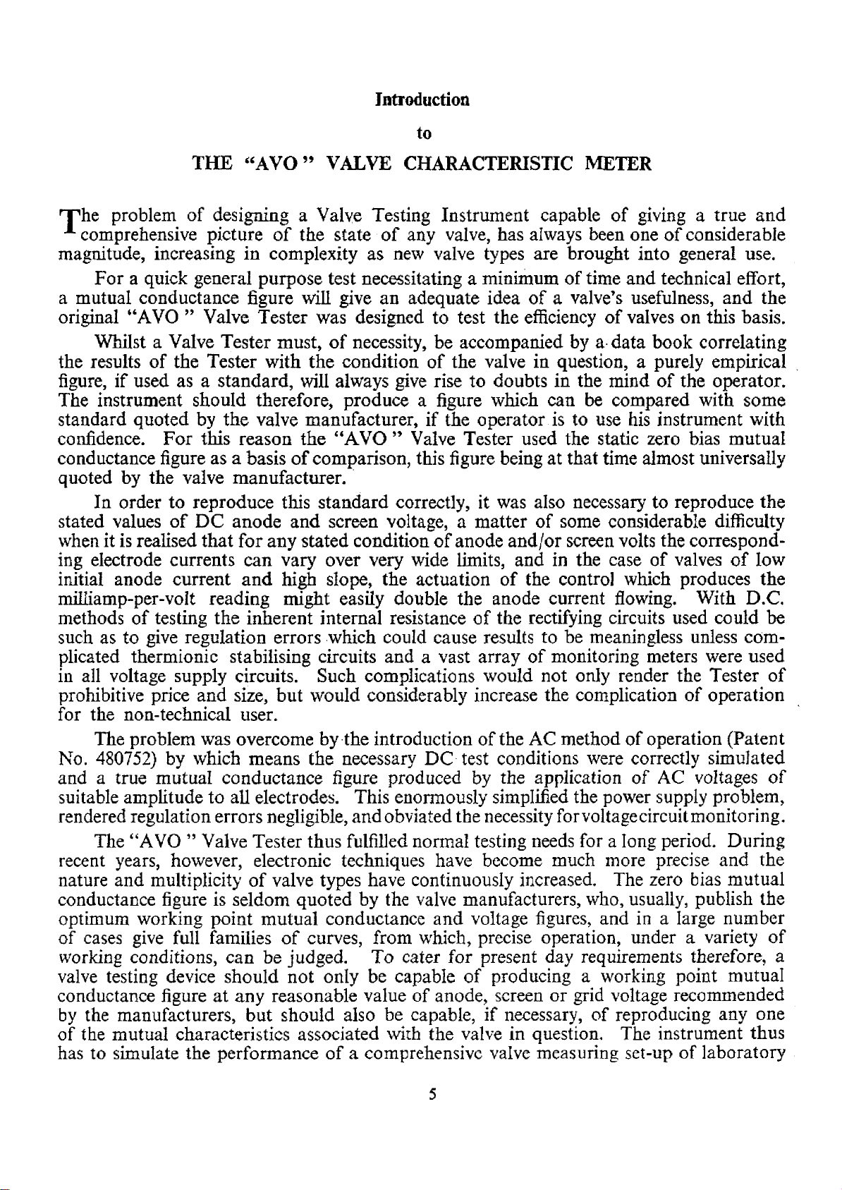
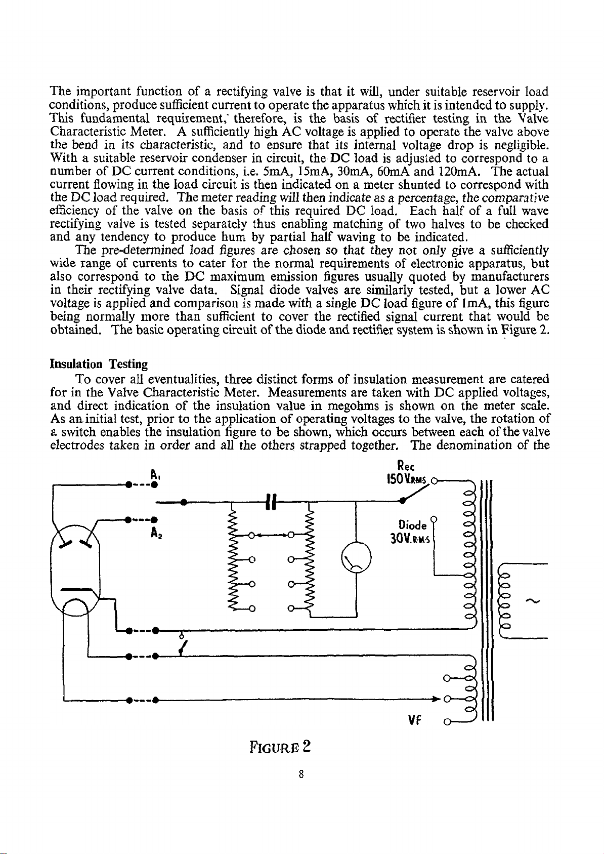
B RITI SH NINE PIN (B 9 ) BR ITIS H SEVEN PIN <B7>
INTERNATIONAL OCTAL ( A 0 8 ) AMERICAN SIX PIN (UX6> BRITISH 4 /5 PIN(BS&B4) AMERICAN FIVE PIN <UXS> BRITISH OCTAL (M 0 8>
B9C
‘ P'TYPE BASE (8 SC )
SUB MINIATURES PIN (M 8)
DIAG R A M OF STANDARD PI N CONN ECTIO NS
AMERICAN SMALL SEVEN PIN (S M 7)
HIVAC FOUR PIN < S M 4 ) HIVAC F IV E P I N (S MS)
AMERICAN FOUR PIN (UX4>
AMERICAN SEVEN P IN (U X7)
B 8A
AMERICAN LOC TAL (B8B)
B 7 0
B9A
(viewed from underside of base)
B 3 0
Page 14

emis sion in a reve rse di rection to normal screen current with the result that the a node
current rises and the curr ent t aken b y the scree n decreases rapidly and becomes neg ative.
Thi s can cause screen overheating and besides giving an unstable and erroneous impr ession
of the cond ition of the valve , can, if al lowed to c on tinue, damage the valve. To obvi ate
this conditio n, the ref ore, the rectif ier is i ncluded in such a manner that only its low fo rward
resistance is presented to th e screen passing c urre nt in t he normal direction, t hu s causing
a negligible variation to standard conditions, but t he reverse resistance of the rectifier
is o perative to limi t screen current of the op posite di re ctio n t o negligible propor tions
and thus prevent the condit ions st ated abo ve, fr om co mi ng into effect.
The problem of self oscillation has been a lmost c ompletel y eliminated in the
“ AVO ” Valve Characteristic Me ter Ma rk II by s to ppering the Roller Selec tor Switch,
and wirin g the Valve Holder Panel in conne ction loops of predetermined lengths, so
that any valve inse rted would tend to oscillate at a definite frequ ency dependent on the
loop lengths. T hese sepa rate inter -c onnection lo op s are then loaded so that oscillation
cannot occur when testing valves wi th conve nt ional characte ristics, irrespe ctive of the
Valve Hol der and pin combination used. In earlie r models, every attempt has been made
to reduc e t he poss ibility of oscill ation by the discreet use of st oppers where ver possible
and t he careful lay out of wiri ng i n cases wh ere it is known that high slope valves are
likely t o give rise to trouble of this nature.
Special procedure for Valves having Internally Connected Pins
The notes which follow relating to valves having internally connected pins do not apply
to the Valve Characteristic Meter Mark II and can be ignored. Here where * appears in the
Selector Switch number, denoting an internal connection, it is merely necessary to set the
appropriate Roller to e.g. U.81 where the Selector Switch reads **9 **8 230 set the Roller
Selector Switch to read 009 008 230 and test as a normal valve.
On certain valves of rec ent manufacture, particularly the miniature glass type employing
B7G, B8A, B9A, etc., b ases it has become the p ractice of m anufacturers to connect
internally certain of the valve electrodes to pin s which would otherwise b e blank and free
fro m any connection. Alt hough the manufacturer s specify the pins on which this is likely
to occur they rese rve the right to vary the nature of the internal connections from time to
time as prev ailing c ond itions might demand. This i n itself preven ts the inclusion of the
electrode thus inte rnally connect ed, in t he normal selector switch se t-up of the valve.
The pins on which this arrangement occurs however, cannot be connected to earth
(O) on the roller switch, for this may re sult in an elec trod e being sh orted to
earth with pos sible damage to the instru ment. Therefore, where this possibility is
kno wn to exist a symbol “ * ” a ppears in p lace of the relevant pin con nection in the
valve set up numbe r, (see “ AVO ” Valve Dat a Manual) to ensure t hat the preliminar y t est
for electr ode ins ulatio n is carefully carried out befo re normal test procedure is brought
into effect.
Where “ * ” a ppears in the set up numb er substitut e ^ whe n setting up the selector
switch. Before inserting valve, ensure that Ci rcuit Se lector switch is in position Ch eck (C)
and apply t he normal Electrode Leakage Test. This will enable th e unknown electrode
connection to be obtai ned as follows :—
(1) By ro tati ng the Electro de Leakage switch, a “ short ” will appear at th e position
“ C ” in ad dition to one or more other electrod e position s, depending on the number
of internal connections. If now t he rollers assoc iated with the valve pins designated
34
Page 15

^ “ * ” ( c m t^ie set UP) are rota te d, the short will be cleared when the roller(s)
electro de indica tion is the same as the elec trode t o which the pin(s) in qu estio n is
internally connect ed. Th e final set up which clears all short s will obviously be the
correct one for the valves and normal testing ca n thus proceed.
e.g. if set u p reads 41236*100
Set ro llers t o read 412361100
On proce eding as above, it is found that a short occurs on “ C ” and “ G ”
positions of Electr ode Leakage switch : On rota ting rol ler No. 6 to when the
set up reads 412364100, the indication of shorts will have bee n removed and normal
test procedure can be followed.
Thi s method will satisfactorily de al with all interna l ele ctrode connections
(A, S, G, etc.) with the exception of t he case where the int ernal connection is made
to a point on th e he at er (this may be eit her end or c entre tap).
(2) In such a case, a short will app ear at the “ C ” positi on of the Electrode Leak ag e
switch, but at no other electrode positio n (as “ H ” posi tion norm ally shows short
circuit denoting heater continuity). Rotating the correspondin g ro ller in this case
will merely change t he “ short ” i ndication to some other electrode designated by
the roller position.
Remove the valve from its socket and carry out a continuity test with an ordinary
ohm meter between the pin on which the unknown connection occurs and all standard
pins connected to he ater. The ohmmeter must be used on a low enough range to
distingu ish betw een “ shor t ” and the heater resistance. The point on the heater
(H —, H-f- or CT) showing zero resistance to the pin in question will now
determine the set up nu mber, and the ro ller must be rotated according ly.
E.g. If se t up is 41236*100
and on ohmmeter check, zero resistance is sho wn betw een pins 6 and 3, set up for
all tests will be 412362100.
It should be noted that if after switching to Ch eck (H ) the indicator lamps are
very dim, a nd valve heater does not li ght up, it is prob ab le that the valve filament
volt age is being shorted o ut, due to the wrong side of filame nt voltage be ing
connected to the int ernal connection pin, and this fault can be c leared by reversing
the heater conn ectio n to the pin marke d “ *. ”
(3) When no in dication of electrode leak age, other than normal he ater con tinuity ,
occurs at any position of Electrode Le akage switch, the pin(s) marked “ * ” have
not b een connecte d i nternally and normal pro cedure can be followed in testi ng the
valve, the roller position marked “ * ” b eing set a t
THE CONTROLS ON THE FRONT PANEL
THEIR FUNCTI ONS AND OPERATIONS
All the co ntr ols necessar y for car ry ing out the essentia l valve tes ting functions are
situated on the front panel of the ins trument, a nd by the ma nipu latio n of t hese controls
and the use of the valve panel already desc ribed , the following tests can be unde rtaken.
1. The direct in dication of insu lat ion resistance between electro des with the valve
cold. T his test will also indicate heater continuity .
2. The direc t ind icati on of insulatio n resistance between specific electrodes with th e
valve filament hot, including a sep arate tes t for the import ant func tion of cathode
to heater insu lation.
3. The measurement of mutual conductance directly in milliam ps/volt over a full
range of applied high tension and bias voltages.
15
Page 16

4. The compa rativ e indication of valve goodness on a coloured scale on the basis
of mutual co nductance reading.
5. The abilit y to plot com ple te sets of mutual characteristics Ta/Vgj, Ia/Va, Is/Vgj,
Is/Vs, etc., with a complete range of applied clectr ode voltages c orrespo nd ing to
D.C. opera ting cond itions.
6. The test ing of rectifiers under reservoir condenser cond itions with a full range of
D.C. loading.
7. The tes ting of signal diodes un der su itable D. C. load.
8. The testing of the separa te sections of multiple valves, the non-operative section
of the valve being maintained at reasonable workin g electrode voltages.
9. The indication of grid current and valve softness.
10. The possibility of testing valves with suitab le loads i nclud ed in the anod e or other
required electrode circuit, together with the abilit y to read the required electr ode
current on a separate meter of greater sensitivity if de sira ble, thus rendering the
instrument suitable for making tests on non -standard and specialised type s of
valves not catered f or in the normal ci rcuit arrang ements.
The separate fu nctions of the controls a vail able are as follows :—
The Set ^ Control.
This control enables minor adjus tments to be made to the input tapp ings on the mains
trans former after the coa rse mains tapping has been set.
The Electrode Leakage Switch
This switch serves t he dual purpose of putting the instrum ent in a condition f or the
initial setting of the Set ~ cont rol and also indicates the e lectro des, if any, between which
leaka ge occurs with the valve in a cold conditio n. It also serves to indicate heater contin uity.
The Circuit Selector Switch
This is a six position switc h enabling the instrument to be set up in readiness for the
type of test to be un de rtaken. All the ne cessary internal circuit co nnections are made to
satisfy the test conditions required, whilst internal test circuits, un nece ssary to the
measurements in quest ion are automatically removed from the valve.
On position Check (C) t he instrume nt is set up for the initial mains volta ge ad justment ,
also on the same posi tio n the Tester is suitably connected fo r the cold el ectr ode leakag e
test, to which we have already referr ed.
At the Check (H ) position of the switch, the valve is automaticall y t ested for electrode
leakage, with the heater hot, be tween the cathode and heater strapped, a nd all other
electrodes.
At po sition C/H. ins th e v alve is automatically tested for catho de to heater insulati on
with the valve hot.
Wit h the cir cuit selector turned t o Test all normal mu tual characteristics ar e measured
in con jun ction with t he electrode vol tage controls, the meter and an ode selector switches
and other relevan t controls. It will be noted that in the case of t he insula tion tests the
meter is automatically shu nted to the appro priate sensitivity and the insulation scale can
be r ead directly. On t he Tes t position of the Circuit Selector switch, however, the meter
rang e selec tor is brought into circuit , thus enabling the meter range to be suited to the
current measurement to be unde rtaken.
The switch setting Diode and Rec are for carry ing out reservoir load tests on diodes
and rectifiers, re spectively. In the case of the diode test the Meter Selector shou ld be set
to th e 1mA position, whilst when testing rectifiers the Meter Selector is set to a value , on the
inner scale, suit ed to the load on which it is desi red the rectifier should be tested.
16
Page 17

The Anode and Screen Voltage Switches
As their names imply these switches enable the requisite electrode voltages to be applied
to screens a nd anodes of valves fo r the purpose of carryi ng out mutua l characterist ic
measurements . They are normally ca librate d in the equivalent DC vo ltage settings and,
therefo re, no account nee d be taken of the actual value of AC voltage which appears at
the electrodes of the valve, which, as already explained, will differ fro m t he equiv alent DC
valu e marked at the switch position.
The Heater Voltage Switches
This dual switch combination is for adjustment of the heater voltage applie d to the
valve under test. To enable a very wide r ange of heater voltages to be o bt ai ned the settin gs
of the two switches are arrang ed to be additive. Thus, with the rig ht hand switch set at 0
all useful voltages betw een 1.1 a nd 16 can be applied to the valve by the left hand switch,
whilst with t he right hand switch at any figure above 0 the value indicated on the right
h and switch shou ld be added to the indicat ion of t he left hand switch. For example, with
the left hand switch set at 5 a nd the right han d switch a t 80, the heate r voltage applie d
to the valve will be 85.
The Negative Grid Voltage Control
A continuously variable co ntrol calibrated 0—10 and marked Neg Grid Vo lts
enables the initial negative bias at which a test is made, to be set at any value between
0 and — 10 volts, with the bias multiplier sw itch set at Vg x 1. With thi s switc h set at
Vg X 10 the bias range cov ered by th is control is increased to 0—I00V negative.
The Press Buttons
Immediately underneath the mov ement will be found a row of three bu ttons marked
respectively G as, Re- Set and mA/V. As their names imply these are for the indicati on
of grid current, the re-setting of t he automatic cut-out, and the direct reading of mutual
conducta nc e in mA/V after the initial valve test conditions have been set.
Th e mA/V button applies a small sup plemen tary change of grid bias in a positive
dir ect ion to the grid of the valve after the latt er has been correctly set up in ac cordance
with th e dat a given in the “ AVO ” Valve Data Manual or alternativel y, with the maker’s
characteristic details. The i nitial anode current having been obtained and the meter
indication bac ked off by the ba ck ing of f control, th e pressing of this button will cause a rise
in the ano de cur rent which will i ndicate on the appropriate meter scale the mutual con duct
ance of the valve directly in mA/V. This test also serves as a comparison test of valve
goodness in con junct ion with the coloured meter scale and Set mA/V. c ontrol.
A change in anode current consequent up on t he pressing of the Gas button
will indicate the p resence of grid current in the valve, the relative magnitude of which can
be assessed from a knowledge of the mutual c onductance of the valve and the c hang e in
current obtained.
When the presence of a damaging short causes the cut-out to operate, th e lamps
behin d the meter will be ex tinguishe d and voltages will be removed from anode and screen
circuits of the valve. After havi ng inv estigated and removed tin cause of the short th e
instrument may be put i nto operation again by the pressing of the Re-Set button, t he
correct condition being shown by the illum ination once ag ain appearing beh ind the meter
scale plate.
The Set Zero Cont rol enables an initia l anode curr ent reading for the valve to be backed
off prior to th e taking of mutual conductance readings, the direction of the co ntrol being
1 7
Page 18

such that an anti-clockwise movement of the knob will cause the meter nee dle to approach
zero.
The Meter Selector Sw itch is a combination switc h serving to shunt th e meter
sui tably to the cu rrent measurement to be undertaken and also to inser t the right va lue
of load when mak ing tests on rectifiers and diodes. It has two sets of calibrations, the
outer ring of figures marked 100, 25, 10, 2*5 and mA/V is for use when the curr ent selector
is at position Test, and serves to indicate the full scale deflection current for the move
ment in milliamps when takin g anode current figures, and similarly represents full scale
reading in mA/V wh en taking mutual conductance figures. The la st position ma rked
mA/V in dicates that the inst rument is correct ly switched fo r the use of the mA/V Control in
co njunction with the colour ed comparison scale on the meter.
The inner ring of figures marke d 120, 60, 30, 15, 5, 1 represe nt the load curre nt
ass ociated with the coloured scale when taki ng rectifier tests wi th the circui t selector on
Rec or Diode. Thus if the valve is rated at say 60 mA per ano de, the Meter
Sel ector Switch should be turned to “ 60 ” on t he inner ring of figures and the c omparative
goodness of the valve wit h reference to this basic figure will be shown on the coloured scale.
Note that when the Circuit Selector switch is set to Diode for testing s ignal diodes,
the Me ter Selecto r should always be turned to posi tion “ 1 ” and the coloure d scale
then o perates w ith reference to a load current at 1mA, a suita ble figure for sig nal diodes.
The 1mA sett ing of the Meter Selector do es not apply to rectifier load tests with t he Circuit
Sele ctor switch at Rec.
The S et mA/V Control, mark ed 1—15mA/V is for the rapid checking of the oper ative
good ness of a valve on the basis of mutual co nductance, after the valve has been set up
for nor mal tes t, and the anod e current backed off to zero. After t he Met er Selector is
turned to position mA/V, the mA/V Control should be turne d to the rated mutu al
conductance figure fo r the valve i n question. The pressing of the mA/V button will
iiow caus e the meter needle to rise and its position on the coloured scale will denot e o per ative
valve goodness.
The Anode Selector Switch marked Al5 A2, S, enable s sepa ra te tests to be m ad e on
multiple valves, and also makes possible the taking of Scr een (or ga) characteristic s. With
thi s s witch turned to “A ± ”, the figures of anode current and mutual condu ctance shown
on the me ter are relevant to the anode designat ed on the set up roll er by As s uch
the switch is in position f or measurem ents on all single e lectrode system valves (tr iodes,
pentodes, etc.). This position also serves for the first half of doub le valves (double triode s
etc.) and for the triode or pentode section of multiple diode valves (double-di od e-triode,
etc.). A sim ilar sett ing of this swi tch serves for the t riode or oscillator section of frequen cy
changers.
With the Anode Selecto r switch a t position “ Aa,” the indicator meter will sh ow ano de
current and mutual conduct ance associated wi th t he second an ode of double valves, the
mixer an ode of fr equency change rs and all anode systems a ssoc iated with the set u p
figure I In this condit ion the first ano de is not left fl oatin g, but h as the normal anode
volts s upplie d to it via a lim iting resistanc e.
With the Anode Selector s et to “ S ”, the current meter is inserted in the screen (ga)
circuit of valves and screen curre nt will thus be indicated. When making this test, anode
voltage is aut omati cally appli ed to all anodes in the valve. Note that in the case of a double
pentode valve, the current indicat ed will be the combined current of both screens.
When the Circuit Selecto r is swi tche d to position Rec and Diode, then pos itions
“ A t” and “ A ,” of the anode selector switch c orrespond to dio de anode 1,
and diode anode 2 respectively, i.e. : to the electrod es associated w ith the selector switch
number ® and *
1 8
Page 19

The Specia l A djustment Panel at the rear of In strument
This will b e uncovered by th e removable plate at the ba ck of th e instr ument and th e
following will be e xpose d to view,
(a) The coarse setting for the app lied 50/60 ~ mains voltage marked 100/115, 200/215,
220/230, 240/250, the setti ng being made by mea ns of th e plug on this small sub
board, to th e tappi ng mos t nearly corresponding t o the nominal mains voltage,
(b) The fuse holder cap which may be unscre wed re veal ing a small cartridge fuse whic h
may be thus easily replaced if blown. Th e co rrec t value for this fuse is 2.5 amp .
(c) The link shorting out two sock ets for the insertio n of resistance, meter or oth er load
in the anode circu it.
GENERAL PROCEDURE FOR T ESTING A VALVE
1. After hav ing set the coarse mains voltage plug at the rear of the instrument
to su it the supply voltage, connect mai ns lead to supply noting that red and black leads
are live and neutra l. The green or yellow lead is the Earth connect ion. Switch on and note
that illumi nation appears behind the trans parent meter scale. The va lve to be te sted
should not be inserte d at this stage.
2. Turn the Cir cuit Selector switch to position Che ck (C) and Electrode Leakage
switch to position “ ^ .” The instrument needle sh ould now rise and assume a position
near the black region of the ins ulat io n scale denoting zero ohms. Rotate t he Set -v co ntrol
until the meter needle assumes its nearest point to the red line in the middl e of th is black
scale markin g. With a correct se ttings of the init ial mains volt age adjustment rotation
of the Set -v co ntrol s hould ena ble the needle to b e moved on either side of the red arrow.
If this is no t the c ase and rotation of the Set ^ co ntrol does not enable the needle to reach
its sett ing mark from e ither direction , t hen the initi al mains set ting should be moved to
the next appropriate tapping. This tap ping sho ul d be hig her than the one chosen if the
needle always appears to t he righ t of the red mark and lower if to the left.
3. Having set up the accuracy of the ins trument to conform to th e applied main s
voltage, refer to t he “AVO” Valve Dat a Manu al, or alternativel y to th e maker’s characteristi c
d ata for the valve a nd se t up the appropriate valve holde r connecti ons on the Valve P anel
sele ctor switch as already e xplained.
Set t he heat er voltag e switch to its correct value for the valve and insert it in the
appropriate valve holder, with out moving the Circuit Selector swi tch from its position
Check (C). Rotate t he Electrode Leakage switch throug h its various el ectrode posit ions
star ting with the ext reme co unter clockwise position marked “ H ”, At posit ion “ H ”
the meter should show a short, thus indicating heater continuit y. Thereafter any r eading
obtained on the i nsu lation scale of the meter will show an elect rode insulation bre akdown
correspon ding to the electrode indicated by the Electrod e leakage switch setting. (Th us
a r eading on th e meter of 1 meg ohm when the Electro de Leakage switch is set to position
“ Gi ” and position “ S ” will indic ate that a cold insulation breakdown of 1 megohm is
occurring between the grid and screen elec trodes of the valve.) It will be noted that
whe rever el ectrode l eakage occurs, indication of this will be sh own at two positions of the
Electrode Leakage s witch, because, obviously, le akage must oc cur betwee n two points.
In the case of br eakdo wn to heater fro m any other electrode, such l eakage indicat ion will
only occur at on e switch setting subse quent to the initial se lector setting, which should
automatically s how zero ohms to deno te heater c ontinuity.
4. Having ensured that no col d leakage path of an y magnit ude is present in the valve
to be tested tu rn t he Cir cuit Selector switch to Ch eck (H ). Allow a few mom en ts for the valve
1 9
Page 20

heater to warm up and note if any meter deflection oc curs. Such a deflection would denote
in megohms th e amoun t of in sul ation breakdown that occurs between cathode and hea ter
strapped and all other electrodes of the valve when h eater volt age is applied. Note tha t if,
for any reason, the Circuit Sele ctor switch is turned ba ck to Check (C) there will,
in all probability, be an indication of an appar ent cold ele ctrode in sulation breakdown
between a number of the valve elec trodes. This need n ot b e the caus e and the read ing
will be found generally to disa ppear after a few moments. Th e rea so n f or such an indication
is o bvious when it is realised that the va lve cathode h as been heated durin g the Check (H )
test. When returning to the Check (C) position, therefore, the cathode is hot and still
emitting. What app ea rs to be a temporary electrode breakdo wn, therefore, is in fact t he
indication of emiss ion which disappears as the he at er or cathode cools.
5. Turn Circuit Selec tor switch to C/H. ins when any cath ode to heater insulation
br eakdown which occurs w ith the heater hot will be shown on the insulation resistance
scale of the meter. No set rule for the rejection of a valve on th is score can b'e laid dow n,
but it will be realised tha t in many circuits w here an appr eciable potential exists between
heater and c athode such as, for instance, in c athode fol lower circuits or DC valve ampli fiers,
the presence of a heater to cathode breakdown of the order of megohms can often give
rise to quite serious trouble. Heater to cathode ins ulation breakdown, eit her permanent
or variable, can also give rise to noise in v alve ampl ifier circuits. If, on t he other hand, the
value of cathode to heater circ uit resis tance is onl y of the order of a few hundr ed ohms,
as for insta nce where ca thode biasing is used with high slope valves, then a cathode to
heater insu lat ion breakdown of th e order o f fracti ons of a megohm need not give rise to
any serious tro uble.
6. The next test normal ly to be made upon the valve is the measurement of some
or all of its mutual characteristics. This ma y ta ke the form of the complete plott ing of
on e or all of its cha racteristics , or the measurement of its mutual conductanc e, or the
compa rative te sting of the valve on th e basis o f its mutual conductan ce. All t hese require
the manipulation of the main volta ge and meter co ntrols and, before s uc h a test is under
taken and the Circuit Selector sw itch turned to position Test, one should be assured that
all the requisite controls ar e correctly set. This applies to the sett ing of the anode, screen
and grid voltage controls, the Meter Selector and the Anode Selector switches. In particular,
where the probable anode current of the valve is unknown, the Meter Selector should be set
to 100 mA to avoid damage to the movement, if the current flowing is such as to be considerably
higher than that catered for by the lower meter range positions. I t is always perfectly
simple an d safe to s et th e Meter Selector at successively lower full scale curr ent
deflectio ns to cater for a valve, the anode current of which is less than that whi ch can be
appro priately read on a higher r ange. If the reverse procedure is adopted, however, then
it is quite possible tha t a damaging current may have passed through the meter circuit
before the latte r is set to a suitable high range. The procedure for taki ng the n ecessary
valve measureme nts is then almo st sel f expl anator y.
Where only a measurement of m utual conducta nce is re quired then t he data for this
can be tak en from the “AVO” Valve Data Manual. Th e el ectrode vol tage settings sh ould
be mad e as indicate d an d consequent upon such settings an initial anode current will be
shown on the meter wh ich has been finally set to a suitable range. This anode current rea d
ing s hould normally be compared with t he anode c urrent reading shown in the t ables, as it
will give an initial ind ication of the valve “ goodness ”. Quite obviously if a valve shows
an anode current rea ding considerably below that which is appropriate for the applied
electrode v oltages, then its emission is much lower than would normally be expe cted and
in normal c ircumstances the valve will not function at full efficiency. Mo re particularly
20
Page 21

does this apply in the case of valves used either as o scillators or output valves, for in both
condit ions the valve has to deliver an appreciable power which cannot obviously be up to
standard if the emiss ion is low. At the s ame time care should be taken not to jump to
false concl usi ons on this basis when testing valves of very high slope and short grid base,
where i t m ay be possible to double the valv e anod e curr ent for a change in bias of some
‘25V, and a very slight variation in the va lve characte ristics may give rise to an erroneous
impr ession of the valve’s “ goo dness ” on the score of a node current. Afte r having
obt ained th e ini tial anode current re ad ing and obtained therefrom such information as is
desirable, this anode curre nt indication may now be ba cked off to zero by the Se t Zero
control an d the Meter Selector sw itch re-set to a range appr opriate to the exp ected reading
of mutual conductance. By pressing the mA/V button the mutual conductance of the valve
will then be directly indicated on the meter, the reading in mil liamps obtaine d being
indicative of the mutual co nductance in mA/V.
Alternatively, wher e it is not necessarily required to obtain a precise readin g of mutual
conduct an ce , but merely a gauge of the valv e’s goodness fa ctor on the basis of mu tual
conductance, then af te r backing off to ze ro the Meter Se lector s hould be set t o position
mA/V and the Set mA/V control set to a value correspondin g to the standard mutual
condu ctance reading for t he valve. On pressing t he mA/V butt on t he com par ative
goodness of the valve will then be show n on th e colou red scale which is divided in three
coloured ba nds. A ll valves coming within th e green portio n can be take n as satisfactory.
Valves in the red po rt ion are suitable for rejection, whilst the small intermediate band
betwe en the gr een and red portion s denotes a valve which, wh ilst not entirel y unsatisf actory,
is not by an y means working at its full rated efficiency. Subs equent acti on on the valves
whose test figures come wi thin this band will obviously ha ve t o be rela ted to the particular
requiremen t of the moment.
W here more comprehe nsi ve tests of the valve are required, to assis t in the solution
of development or more intricate tes t probl ems, th e plotting of one or a family of mutual
ch aracteristics can oft en give a much more complete answer. This may readi ly be under
taken with the Valve Chara cteri sti c Meter and is performed with the Circuit Sele ctor in
its position Test. The man ipulati on of the co ntrols subsequent to the o btaining of
the in itial ano de current readings is not of course re quired, it being merely necessar y to
plot the value of the appropriate elec trode curr ents as re ad from the mete r, against the
settings of the associated el ectrode volt age switches. I aj\g x curves will be taken at a
pre-determined setting of anod e and/or screen volts, the readin g of the anode current
obt ained b eing pl ot te d a ga inst the settings on the variable grid bias control. Similarly
Ia/Va curves will require a fixed set ting of grid bias, anode current being plotted agai nst
the settin gs of t he ano de voltage switch.
Where either m utual conductance characteristic curves are requi red for the screen
or g2 of th e valve in q ue stion, then the Anode Selector sw itch should be set to positi on
“ S ”, the me ter current shown will be an indication of the screen (or g^ current and all
the above instruct ions can be related thereto.
Remarks in relati on to the tests describe d abov e as applied to multiple or special type s
of valve, will be fou nd in subsequent test notes .
7. Where a valve is suspected of passin g too mu ch gr id current, a measure of the
magnitude of grid curr ent at th e desired conditions of applied electrode voltag e may be
made a fter having measured the mu tual conductance of the valve in question. After hav ing
set the val ve up and backed off the anode current to z ero as for mA/V test, the button
marked Ga s should be pressed. Any grid curr ent flowing will set up a DC grid voltage
across the 100,000 Ω r esistance introduced into circui t. This will result in a change in
21
Page 22

anode current (usua lly forward) depend en t upon the polari ty of the voltage d eveloped across
the resistor. The value of the grid current flowing will then be calculated from t he formula
A la X 10
Ig (μΑ) =
---------------where Ala is the a node current change, a nd g is the mutual
g
condu ctance in mA/V. The dire ction of anode curr ent change will denote the nature of
th e grid current flowing.
S. The testing of rectifying valves should rea lly be associated wi th the requirements
of the circuit in which these val ves ar e to work, although in most cases, in the data for the
valve in question a figure is quo te d denoting the standard emis sion to be expected for a
valve of the type under test. Th e proce dure for car rying o ut the test is again str aightfor
ward. All initi al tests should have been ca rr ied o ut as for amplifying valves, but instead
of set ting Circuit S electo r t o Te st fo r the measurement of mutual characteristics, the circuit
selector should be set to position Rec after having turned the M et er Selector to a load
current range appropriate to the valve. This load current, it will be reali sed, appl ies
to one anode only. The setting of load current can eith er be determined fr om th e
tabulated data as alread y mention ed, or alternatively can be related to the tota l current
that t he valve is required to deliver. Th us in a piece of apparatus where the total HT
current dra wn is say 50mA , then a rectifier load current setting of “ 60 ” will be an adequate
test for the valve emission (assuming half wave rectifi cation.)
Alternatively, if the valve is a new one, the maker’s rating for maximum load curr ent
can be used as the basis for the settin g of the meter range switch. It will be realised that
since each half of a ful l wave valve is tested independently, then the setti ng of the r ange
switch should ind icate half the total valu e of current t hat the valve would be exp ected to
deli ver in a full wave ci rcuit. For instance a valve rated at a ma ximum c urrent of 120mA
w ould be tested with each anod e at the “ 60 ” po sition on the Meter Selector. No further
manipulation of the electrode voltag e co ntro ls is r eq uired. T he heat er voltage is already
set whils t anode, grid and screen v oltage control s are completely d is-associated from the
test circuit by the s etting of the Circuit Selector swit ch to Rec, aU appropria te volta ge and
ci rcuit connections also being automatically made. Having, therefore, correctly set
up th e valve as explained, the i ndication of the meter needle on the coloured scale will
show the oper ative goodness of the va lve in relation to the stand ar d load current chose n.
Sim ilar remarks app ly to the te sting of signal di ode valves, with the exception that
the se are al ways tested wit h t he Met er Selec tor at “ 1 ” and the Circuit Selector at posit ion
Diode.
INS TRUCTIONS FOR TESTING SPECIFI C VALVE TY PE S
The function of a valve, as distinct from its manufac turer’s type number is indic ated
by a symb ol in the form of letters appearing at the extreme right of the test data ; thus a
half wave re ctifi er would have t he letter “ R ” i n the function column, whilst a full wave
rectifier would be designat ed by “ RR ” . Similarly, diode valves will be shown by the
letter “ D ” the number of diode eleme nts being indicated by the numbe r of “ Ds ”, th us
** DDD ” refer to a triple diode.
Th e testing of multiple diodes or rectifiers is carried out in the manner already explained,
the An ode Selecto r swit ch being used to select the di ode or rectifier element, the emissio n
figure for which , being indicated on the m eter. It will be reali sed t hat wh en dealing with
diodes or rectifiers A x and A2 positions of the se lec tor switch represen t d io de or rectifier
anodes 1 and 2 respectively and correspond t o figures S and 9 in the set up figure.
22
Page 23

In the case of t riple diodes since only two an ode systems are no rm ally catered for ,
a special procedure is adop ted in the set up figure. At t he position in the set up number
representing t he third d iod e th e symbol f is included, the first an d second diodes being
indicated by 8 an d 9 respectively in the n ormal way. The valve should now be tested
normally with the selector switc h set to 0 whe re the f appears in the set u p n umber. This
will give emission figures for di odes 1 and 2. Now rot ate the Selector Switch rollers so
that the two ro llers origina lly set at 8 and 9 are now set to 0 and set up the position f as 8
on the s elector switch. A fu rther test w ith the ano de selector switch at Ax will thus give
the emission of the third diode , e.g., AAB1 will be indicated in t he data as 0231|0980.
T o test diodes 1 and 2 the set up on the roller sw itch will be 023100980 and diodes 1 and 2
will be test ed in the normal manner. Fo r o btaining the emission figure for the third diode
the Selector Switch w ill be altered to 023180000 and the Anode Selector to posit ion A v
Double Trio des or Double Pentodes will be indicated by the le tters “ TT ” or “ PP ”
in the type column and will be tested in the nor mal way for ea ch half of the valve, selection
being made by th e rotat ion of the Anode Selector switch to o r A2 co rresponding to set
u p figures 6 and 7.
Combined Diode and Amplifying Valv es will be represente d in the type columns by
“ DT ” and “ DDT ” for diode triodes and double d io de t riode s, whilst “ DP ” and
“ DDP ” indicate diode pentodes and double d iode pento des. The tes ting of such valves
is automatic* the amp lifying section being test ed first with the C ircuit Selector switch at
position Test and the Anode Selector at posit ion “ A t ” whilst t he rotation of the Ci rcuit
Selector s witch to the Diode position will automatically set the instrument in readin ess for
testi ng one or both the diode s wit h the ano de selector at A 1 or A2 respective ly, with the
Meter Selector set to “ 1”.
Fre quency Changers of the Hep tode, Hexode class employing the normal oscillator
section as a phantom ca thode for the mixer section are not very satis factorily tes ted i n two
Sections, as the nature of the valve construction is such that each sect ion is dependent on
the other for its correct operatio n. For te st pur poses t herefor e, thi s va lve is shown con
nected as an HF pentode for w hich, where possibl e, ano de current a nd/or mutual con
ductance figures are given. Such valves are indic at ed by the letters “ H ” in the type
column.
An exc epti on to this class of valve is t he Oc tode designated by “ 0 ” in the type colum n
which, as will be seen from the data, is tested as if it had two s eparate elect rode assemblies,
separate data bein g g iven f or each. In th is case the osc illator section is te sted wit h anode
sel ector at A 1 and the mixer sect ion at A2.
A s a further test to ensur e the pro babili ty of such a valve oscill ating satisfactorily, an
indication of failin g e mis sion will poss ibly give the most use ful results . It will be realised
that when a valve is up to s tandard its cathode will develop its full emission at the rated
heater voltage for the valve, and any change in the cathode tempe ra ture will not resul t in
a correspond ing change in the emiss ion. If, however, the cathode’s emission is failing, then
an in creas e or d ecrease in the Cathode temperature will resul t in a noticeable change in the
em ission for the valve. When a valve is oscill ating it tends to run in to the positive grid region,
and thus makes use of the full emiss ion ca pabilities of th e cathode. Any failing emission will
limit its ut ility in this res pect. As a subseque nt test, therefore, on a valve designed to be
used as an o scillator, it is helpful to not e the anode current at the rated test figures with
the normal heater vol tage applie d and then decrease the heater vol tage by about 10 to
15 % (t he next tapp ing on the selector sw itch) for a short period. In the case of a valve
with fai ling emission this will result in an excessive decreas e in the anode current con
siderabl y greater than the per centage decrease in heater vo lts. Such a result would suggest
that the valve will not oscillate ve ry satisfactoril y. A negligible or small decrease in anode
23
Page 24

current (or of the same or der as the heater volts cha nge ) will show that the valve is
developi ng its full emission at the rated heater voltage, and pro vided that the cir cuit
conditions are right it should oscil late normall y.
Frequency Changers employing separ ate electro de assemblies for oscillat or and mixer
functions are designated by “ TH ” (Triode Hex ode) “ TP ” ( Triod e Pe ntode). The separat e
sections of this valve are not interd ependent, as in the case of th e phantom cathode types,
and they can thus be tested in. two separat e s ections as a pentode or triod e respectively.
This arra ngement is catere d for in the set -up figures given, 6 correspondi ng to the triode
section and teste d with th e Anode Selector at Aj whils t 7 in t he set up figure corresponds
to the mixer sectio n which is tested with the Anode Selector at Aa. The f igures to be expected
from both halv es of the valve are given in the table s wh ere available, but it is often informa
tive to apply a test for f ailing ca thode emission to the trio de or os cillator section in the
man ner alr ea dy descr ibed .
In the case of normal triode s and pentodes (incl ud ing beam tetrodes) the test procedur e
for which has already been fully outlined, the type column will show the symbol “ T ”
and “ P ” respectively.
THE USE OF THE LINK ON THE BACK PANEL OF THE INSTRUMENT .
This link is to enable a lo ad to be inserted i nto the a node cir cuit of the valve under
test when an an ode current or mutua l cond uctanc e test is b eing perfor med on the
electrode c ircuit in question. It thus ena bles dynamic figur es for the valve or ele ctrode
system concerned to be obtained, the procedure bein g to remove the shorting link and
ins ert across t he sockets a resistance or other load which it is desired to include in circuit.
Tuning i ndicators (Magic Eye s) are tested with the contr ol s set a cc ording to the figures
given in the se parate data table, using the screen swit ch f or obtaining target voltage and
inser ting the ano de load, sh own in columns marked “ Ra ” by means of the link at the rear
of the instrument. At the approx imat e bias given in the table the tr io de section should be
at cut-of f and the “ eye ” fulJy closed. On varying the grid bias t o zer o the “ eye ” s hould
open fully and th e value of anode current sho uld be appro ximately that app earin g
in the t able. In the ca se of d ouble sensitivity indicators giving multiple im ages
responding to different sensitivities, two sets of data (where possib le) are given, the first
set referrin g to th e more s ensitive indication.
Gaseous Rectifiers
These also necessitate the use of the link, as s uch valves would normally pass a
dama ging current if tested wit hout suita ble limiting load in the an ode circuit. They are,
therefore, teste d not on the re ctifie r or di ode test circui t, but with t he selec tor switch turned
to Test, anode voltage and representative anode current figures bei ng given in the
Val ve Data c olumns. The value of load r esistance (of su itable watta ge) which must be
in cluded across the li nk , befor e the valve is tested, is shown in K Ω in the“ mA/V ” column
(which would not normally apply to a rectifier'valve). Fall wa ve examples of th is class
of valve are of course tested at anode selector switch positions Aj and A 2.
Cold Cathode Recti fiers designate d by the symbol “ CCR ” can be tested in a similar
manner, the anode v oltage, approximate anode cur rent, and load resistance being given
in the data columns as above.
Thyratrons c an be checked by comp arison if set up as a normal triode, with a limiting
resistance included in the link, th e control ratio being indicated by a comparison between
the peak v alue of the ap plied anode volt age, and the se tting of the grid bia s control which
will prevent the valve striki ng and passing anode current. It must be emphasised, howeve r,
that the main v alue of suc h a test is in comparison only, as the hold off grid bia s value
24
Page 25

shown on the gri d bias co ntrol is only approximately half that of the bias which would
normally be requ ired to hold off the anode curre nt of the valve at the peak anode voltage
in question.
Neon Indicator s may be tested for striking, by setting up the roller switch so that
anode and cat hode pins of the tube are set to 6 and 1 respe ctively, all ot her rollers being
connected to 0. A suitable load resistance (normally between 5,000 and 15,000 ohms)
should be inclu ded in the anode circuit link and the anode voltage switch should be set to a
pea k v alue as near as possible to (and in no cases lower than) the striking voltage o f the
neon in q uestion. The striking of t he neon will, of co urse, be in dicate d by a passage o f
anode current s hown on the meter which should be set at a suitably high current range.
It should be n oted t hat wher e the a node voltage refe rs to the peak applied voltage, as in
the case of thyratrons and ne ons, the actual pea k vol tage applied to the valve is hig her
than the indication on the anode voltage switch. To obtain the peak voltage equivalent
to a given sett ing of the anode voltage switch the figure shown o n the switch should be
multiplied by approximately 1 -5 ; thus with the anode voltage switch set to represent a
D C voltage of 100V. the peak applied voltage is approximate ly 150V.
GENER AL PRECAUTIO NS TO BE OB SERVED WHEN
USING THE VALVE CHARACTERISTIC METER
It will be realised that when dealing with an instru ment such as the Valve Characteristic
Me ter with such flexibility of control, it is almost impossible to protect the in stru ment
to such an extent that the o pe rator cannot cause d amage to e ither the valve or the instr ume nt
by some combination o f wrong setting of the controls or incorrect use of the meter. It is,
therefore, impor ta nt that the correc t pro cedure, as previo usly o utlined, should be used in
the sequence of the tests applied. Valves should be tested for insulation or br eakdown
before full voltages are applied for cha racteri stic tests. Where an y doubt whatever exists
as to t he probable electrode current likely to be passed* the Meter Selector switch should
always be turne d to its highest curr ent range and the n g radually redu ced in order to facilitate
reading of the current.
In experimental work where a variable voltage is required to be supplied to the ano de
or screen electrodes of the valve, always sta rt with the lower voltage tapp ings and increase
only after correct adjustments have been m ade to the meter selector circuit to ensure that
the meter circuit is not thus ove rloade d by an unknown c urrent. Always make sure that
the selector voltage switches have been correctly set for the valve befo re the instr ument is
switched on. In this respect it is a good practice to return the selector voltag e switches
to zero (particularly Heater Voltage switches) after a tes t has been appl ied and before a
new valve is inserte d.
Take care in setting the selector switch to avoid wrongly co nnec ting the electrodes of
the valve under test. In this respect the automatic cut -out is advantageous in tha t it will
usually save a valve if high tension voltage is in advertently applied to the heater by incorrect
setti ng of th e switch, but it must be pointed out that after the switch is correctly set nothing
can save the heater from being burnt out if an overload heater voltage is applied by wrong
setting of the heater voltage switches.
D o not a pply test voltages to th e valve without ensuring t hat where necessary top cap
connections have been correctly made, as a valve can often be ir rep arably dama ged by
running it with its grid or its anode wrongly connected.
25
Page 26

Whe re a valve appears t o be performing abnormally, as in dica ted for instance by a
cont inuously rising or falling anode current which does not att ain a condition of stability,
do not leave the valve “ cooking ” for a long per iod to see what will ultimately happen,
as this will in all probability result in the da maging of the valve due to excessive currents
in the anode or screen c ircuit s. In genera l, it is not necessary or helpful to leave a val ve
on test for a considerably lon ger period than is necessary to complete the test in question.
Finally, it must be s tress ed t hat w hilst every ca re has been taken in the compilation of
this publicati on and the “AV O” Valve Data Manual to ensu re that all data given is correct
as far as is known at the time of going to press, it is not impossible that with the many thou
sands of figures involved, errors will have crep t in. The manufacturers cannot hold themselves
responsibl e for any damage that might occur to a valve or to the instrument from such
a cause.
N OTES ON SIMPLE MAINTENANCE OF INSTRUMENT
If on switching on the ins trument and performing the usual test for applied mains
voltage, the meter needle does not indicate, and the lamps behi nd the movement do not
light, th en it can be assumed that the cut-out has operated. This can have been cau sed
by either an internal or external short circuit that has occu rred previously to switching on,
or by a sharp mec hanical shock that can have jolted the relay. The cut- out is reset by
pushing the “reset” button.
Alternatively, the fuse ma y have blown.
First remove the mai ns plug and ch eck the fuse for continuity and if necessary repla ce
with Belling Lee ty pe L.562/2*5 rated at 2*5 amps. Then repla ce the mains plug and re-set
the cut-out. If the cut-out aga in blow s, examine fo r an extern al short on the top panel.
Failure due to an internal sho rt c ircu it s hould be repor ted to the Company.
If the lamps do not light but t he test for mains voltage shows a normal deflection,
then one or both the lamps (the y are in series) m ay have been blown . They should be
removed after having removed the mains plug by withdrawing the mounting bracket through
the ape rture in the re ar of the instrument and f aulty lamps replaced with Osram t ype 6*5
volt 0-3 amp S.E.S. fitting (or equivalent).
It is highly probable that due to variations in manufacture, a numb er of valves
will show te st figures differing widely from thei r normal ratings. If, however, all valves
appear to be read ing consistently lo w or high by a large percentage then it is probable
that either the ap plied voltages or th e movement sensitivity are at fault.
These can be c hecked without opening the inst rument, as follows:—
Fir st check the grid volts between the grid and cathode sockets of a valveholder
using an electronic o r other D.C. voltmete r imposing negligible load. Then wit h any given
setting of th e grid voltage control, the mean D.C. reading obtained between grid and cathode
sockets should be 0*52 x the nominal settin g of the grid control and this should be
ma intained ove r the full span of the co ntrol.
Thus with the control s et at — 6 volts, the valve vo ltme ter re ading shou ld be — 3· 12V
mean D.C., from grid to cat hode.
Similarly, t he pressing of the but ton m arked mA/V sh ould result in a positive voltage
change of 0-52V DC.
Thus with the grid v oltage set as above and the button pressed, the valve voltmeter
should read — 2*6V i.e. (— 3-12 + 0*52).
26
Page 27

Similarly, the applied anode an d scre en voltage s may be chec ked by taking a reading
between an ode (or screen) and cathod e soc kets of a suitably set up valve holder with an
ordinary AC voltmeter. These can b e compared with the appropriate anode or screen
voltage switch setting as follows :—
. r . , AC voltage apparent at Valve Holder
Nominal voltage (D.C.) sett ing of switch =
-------------—
------
— — —
Finally the accuracy of the mo vement may be chec ked by inserting a valve in the Valve
Characteris tic Meter cor rectly set up for test and int roducing a suitable multirange DC
mi llia mmeter across the link on the back panel. On swit ching on, the curre nt reading ob
taine d on the Valve Characteristic movement (read in con junct ion with the meter range
switch) should be exactly twice the current reading on a su itable ran ge of the milliammeter
in serted into the link.
I f any or all of the above re lationships do not hold good aft er mains voltage has be en
correctly set, th e followin g pr ocedu re sho uld be adopted.
(a) If anod e or screen volts do not come within appro xima tely ± 5 % (allowing for any
possible error in the me ter. N.B.—BS 1 allows ± 3|% of f.s.d .) o f the required
relationship, consult manufacturer.
(b) If variab le gr id vol tage doe s not compar e with correct V.V. reading Remove
case of instrument a nd adjust control marked V.G. on small sub-panel on frame
of instrument .
(c) If a wr ong v oltage chan ge is obta ined when p res sin g button marked mA/V—adjust
pre- set control marked G.M. un til correct change obtained.
(d) Wrong relationship betwe en panel movement and exte rnal milliammet er—adjust
pre-set control marked “ S ”, and th en recheck mains setting, e lec trode vo ltages
and m eter sensitivity.
When making tes t measurements as de scribed above, it is of course essential for
the user to assur e himself that he is not misinfo rm ed as to the ac curacy of h is Valve
Characte ristic Me ter by t he use of un suita ble or inaccurate externa l test instruments.
Thus when measuring gri d vol ts, the DC Valve Voltmeter used shoul d have an inpu t
resistance of at l east 100 times th e i nternal resis tan ce of the grid voltage circuit (which
is 20.0000), whilst when checking for accu racy of sc reen voltages, it must be remembered
that a subsidia ry rectifier (see page 12) is always in circuit, and thus an AC Voltmeter
having a resis tance not less than 1,000 Ω per v olt should be used. The ac cur acy of all
similar measurement s should be related to the p robable erro r in the measu rin g instrument
whic h sho uld of course always be high grade.
Enclo sed within this publi cation will be found a quick r eference guide to the operation
of the Valve Charact eristic Meter which is intended only to be used once the i nstru cti on s
within this book have been assimilated.
COPYRIGHT:
No information or diagrams in whole or in part may be copied or reproduced without the
prior permission in writing of The Automatic Coil Winder & Electrical Equipment Co. Ltd.
27
Page 28

Checking details for correctly set up Valve Characteristic Meter Mk.II.
1 . Connect the instrument to a suitable 50" supply of good wave form and with the
coar se mains tapping appropriately se t , adjust the set - control until the meter
needle reads in the se t ~ zon e , with the valve characteristic meter switched to the
chec k mains condi tion.
2 . The unloaded RMS heater volts are not critical and are arranged to compensate
for the volt«3e drop due to th e heater curren t likely to flow and will normally
be +3% and +10$ up on the reading of the heater voltage switc h, e.g. a nominal
6V heater voltage would be read between say 6.2 and 6.6 volts open circuit.
3· The unloaded Anode volts measured with a standardised Model 8 or Model 7
AvoMeter should be such that the KMS reading on the meter equals 1.1 x the
calibration on the panel of the instrument +5
k. The screen voltage should bear a similar proportion to the anode voltag es,
provided that the internal screen limiting rectifier (EA5 0) is shorted ou t.
5a The grid voltage should be such that when measured with a standardised valve
voltmeter , of the D.C. mean reading type, the voltage measured between grid
and cathode should be such that the mean D.C. voltage equals the calibrated
voltage on the panel of th e instrument x 0.525 i··· lOOv negative bias should
read 52.5V mean D.C. This voltage should be accurate to within # division
of the fine potentiometer sca le .
5b Vith th e grid voltage eet to -1 , operation of the mA/V push button should
reduc e the reading to zero ± 2£.
6. Vith the instrument working under the above normal tolerances and presuming that
tha t a valve has been standardised on D.C . , then with the anode and/or screen
and negative grid voltage set to be equivalent to any one setting of the
equivalent D.C. voltages , the anode current of the valve should correspond to
within t 10£ of the absolute anode current measured with Battery D.C . H.T.,
scr ee n and grid voltages and A.C. heater volt age.
The mutual conductance of the valve should also compare with the mutual
conductance obtained from the curve of a valve suitably standardised, as
len t i o ne d in 6 , such that if anode and/or screen voltages are set to correspond
to this under D.C. conditi ons, and the grid voltage is so set that the anode
curr ent is the same as the anode currea t for any given point on the D. C.
characteris tic, then at these two like anode currents, the mutual conductance
should compare within ± % . This tolerance will widen scaewhat when
measurements are mads on very high slope short grid base valves*
8. For an additional check of anode current, the anode current as read on the
meter of the V.C.M. may be compared with the D.C. current read on a
standardised AvoHeter on a suitable D.C. range inserted in series in the
ano de link. The anode curr eat read on the meter of the V.C.M. should be
equal to within t 3% of twice the anode current read on the external AvoHeter
on it s D.C . ranges .
9 * Conn ec t a 2ΚΏ potentiometer between screen and cathode and with 20V applied
from th e screen voltage selector switch, check th at the overload protection
out -o ut releases between and 38mA·
1 0 . Vith the instrument set for the test of a pentode and a suitable outp ut pentode
(KT .3 3 C etc) inserted into the instrume nt, and voltage controls adjusted for an
indic ativ e anode current of SOm A, the valve should not show any si gns , of osc i l l a t i f l a
or running off of anode current, provided that it is an instrument which Is
fitt ed with the later type valve board assemb ly . (Th is is readily identifiable
by examination as the earlier types have a considerable number of screen leads,
whereas th e later modified pattern does n ot ·
U . Vith th e instrument set up for electrode insulation and a valve inserted Into
an Adaptor with a 1X2 resistor connected aero·· H/C and A/3, then with the
requisi te settiaf* for H/C insulation (lot ) and A/3 (C ol d ) the meter should
i ftdie ate 1X 2 t 10*.
Page 29

Setting up details for Valve Characteristic Meter Hark II, which is
presumed to be In working order.
1· Vith a suitable mains voltage applied carry out preliminary check for the
presence of HT, Screen, Grid and Heater voltages, ensuring that they are of
the right order of magnitude and follow their respective settings.
2. Open the anode current link (to the left of the fuse holder above the
coarse mains tap panel at the rear of the instrument), and insert a moving
coil milliammeter in the link. This may be a Model 7 or Model 8 AvoHeter.
Obtain anode current from a suitable valve inserted in the Tester and
checking on each anode current range of the meter selector switch in turn,
ensure that the reading on the external milliammeter is 0.5 x the respective
full scale anode reading on the Y.C.M. meter ± 2%» If this is not so
adjust the potentiometer B.31* marked ' S' on the transformer assembly.
3· Vith RMS (not greater than 200Q/V) A.C. Voltmeter standardised at 220V,
and coarse mains tap on V.C.M. set to approximate mains input voltage, vary
set - switch with voltmeter connected between anode and cathode on either a
valve holder or the top cap board, with the anode voltage «witch set to
200V until the reading on the A.C. meter is 220V BMS t 2%,
J+. Set grid voltage multiplier switch to the x 10 position and set 3.10 to
maximum, i.e. 10V. Vith a standardised valve voltmeter connected between
grid and cathode, again either across a valve holder or the top cap board,
adjust R.5 marked Vg on the transformer assembly, until the reading on the
meter equals 52.5V (100 x 0.525)· Set grid voltage multiplier switch to XL
and with grid voltage control fi.1 0 still at 10V check that meter reads 5*25V
(10 x O.S25). If erroneous adjust connection to H.7/R.8 accordingly. Vith
grid voltage control R.10 set to the IV position, a reading of 0.525V should
be obtained on the valve voltmeter. Operate push button marked mA/V and
the previous reading of 0.525 should be cancelled out exactly. Should this
not be the case, the potentiometer R.12 should be adjusted. This is narked
Gta on the tag board of the transformer assembly. Grid potentiometer
settings should be correct within % division on the potentiometer scale and
should be the voltage marked on this scale x 0,525V. With the circuit
selector switch at the 'check cold' position , operation of the grid voltage
multiplier switched from the x 1 to x 10 position, should show no change
in the movement pointer indication.
5. Remove valve voltmeter from circuit with V.C.M, circuit selector switches set
at the ’ ’ set mainsrt condition, check that the pointer lies within black
calibration mark on the insulation scale* If erroneous it will most
likely be found to be low and this can 1>e compensated by adjusting S.4 (125EQ)
by shunting it with an appropriate high value high stability carbon resistor.
R.4 is I6cated on the underside of the top right hand corner of the tag
board on the right hand transformer looking at the rear of the instrument.
6. It is wise to monitor the 20 0 V anode tapping during paragraphs 2 , 3 and
to ensure that the mains have not shifted. A stabilised supply is not
generally suitable due to wave fora errors.
7. The following checks should be made to ensure that the overload protection
relay is working satisfactorily. A 2KQ potentiometer should be connected
between screen and cathode, as previously either across & valve holder or the
top cap board, and with the anode elector switch set to 'S', the screen
voltage selector switch to 20V, and the circuit selector switch to test,
redaction of the value of the ZSSL potentiometer will cause an increase in
the screen current monitored on the meter, and when this reaches between
3*f and 38 mA, the c u t out should break. Should this not be the case,
adjustment will be necessary by either varying the release spring tension
or adjusting the leaf contacts. After adjustment the above operation
should be repeated.
Page 30

 Loading...