


Re-edited by PD2MRX for adobe acrobat, 2004-2005.
PA2MRX, from 2006.
THE “AVO”
VALVE TESTER Type 160
NSN: 6625-99-943-2419
WORKING INSTRUCTIONS
SECOND EDITION
PUBLISHED BY
AVO LIMITED.
AVOCET HOUSE, 92-96 VAUXHALL BRIDGE ROAD, LONDON, S.W.1
Telephone: VICtoria 3404-9
1

THE “AVO” VALVE TESTER TYPE 160.
2
FOREWORD
For more then a quarter of a century we have been engaged in the design and manufacture of “AVO” Electric Measuring Instruments. Throughout that time we have consistently pioneered the design of modern multi-range instruments and have kept abreast of and catered for the requirements of the epoch-making developments in the field of radio and electronics.
The success of our steadfast policy of maintaining high standards of performance in instruments of unexcelled accuracy, and making such instruments available at reasonable cost, is reflected in the great respect and genuine goodwill which “AVO” products enjoy in every part of the world.
It has been gratifying to note the large numbers of instances where the satisfaction obtained from the performance of one of our instruments has led to the automatic choice of other instruments from the “AVO” range. This process, having continued over a long period of years, has resulted in virtual standardization on our products by numerous Public Bodies, The Services, Railway Systems, and Post Office and Telegraph Undertakings throughout the world.
Our designers have thereby been encouraged to ensure that new instruments or accessories for inclusion in the “AVO” range fit in with existing “AVO” apparatus and serve to extend the usefulness of instruments already in use. Thus, the user who standardizes on “AVO” products will seldom find himself short of essential measuring equipment, for, be means of suitable accessories, his existing equipment can aften be adapted to meet unusual demands.
It is with pleasure that we acknowledge that the unique position by “AVO” is due in no small measure to the co-operation of so many users who stimulate our research and Development staffs from time to time with suggestions, criticism, and even requests for the production of entirely new instruments or accessories. It is our desire to encourage and preserve this relationship between those who use “AVO” instruments and those who are responsible for their design and manufacture, and correspondence is therefore welcomed, whilst suggestions will receive prompt and sympathetic consideration
3
THE “AVO” VALVE TESTER TYPE 160
CONTENTS
|
|
|
|
|
|
|
|
|
|
|
Page |
Summery of Data .. |
.. |
.. |
.. |
.. |
.. |
.. |
.. |
.. |
.. |
.. |
5 |
CHAPTER 1 |
TECHNICAL DESCRIPTION |
|
|
|
|
|
|
||||
1 |
Introduction |
.. |
.. |
.. |
.. |
.. |
.. |
.. |
.. |
7 |
|
2 – 9 |
Principles of operation .. |
.. |
.. |
.. |
.. |
.. |
.. |
7 |
|||
10 – 21 |
Basic circuits .. |
.. |
.. |
.. |
.. |
.. |
.. |
.. |
8 |
||
22 – 25 |
The Valve Holder Panel .. |
.. |
.. |
.. |
.. |
.. |
.. |
13 |
|||
26 |
General Construction .. |
.. |
.. |
.. |
.. |
.. |
.. |
17 |
|||
27 |
Mains Supply |
|
.. |
.. |
.. |
.. |
.. |
.. |
.. |
17 |
|
CHAPTER 2 |
THE VALVE PANEL AND CONTROL UNIT |
|
|
|
|
||||||
28 – 33 |
The Valve Panel and Selector Switch |
|
.. |
.. |
.. |
.. |
20 |
||||
34 – 36 |
Procedure for setting up Valve Base Connections |
.. |
.. |
.. |
21 |
||||||
37 |
Provision for new Valve Bases .. |
.. |
.. |
.. |
.. |
.. |
23 |
||||
38 |
The Control Unit and its Function |
.. |
.. |
.. |
.. |
.. |
23 |
||||
39 – 41 |
The Mains Voltage Selector |
.. |
.. |
.. |
.. |
.. |
.. |
23 |
|||
42 – 47 |
The Circuit Selector |
.. |
.. |
.. |
.. |
.. |
.. |
.. |
24 |
||
48 |
The Electrode Selector .. |
.. |
.. |
.. |
.. |
.. |
.. |
24 |
|||
49 |
The Heater Voltage Switches .. |
.. |
.. |
.. |
.. |
.. |
24 |
||||
50 |
The Anode and Screen Voltage Switches |
.. |
.. |
.. |
.. |
25 |
|||||
51 – 52 |
The Anode Current Controls |
.. |
.. |
.. |
.. |
.. |
.. |
25 |
|||
53 |
The Negative Grids Volts Control |
.. |
.. |
.. |
.. |
.. |
26 |
||||
54 |
The Set mA/V Control .. |
.. |
.. |
.. |
.. |
.. |
.. |
26 |
|||
CHAPTER 3 |
OPERATING INSTRUCTIONS AND GENERAL PROCEDURE FOR |
|
|||||||||
|
TESTING A VALVE |
|
|
|
|
|
|
|
|
||
55 |
The connection of the instrument to a supply voltage |
.. |
.. |
.. |
27 |
||||||
56 |
Final setting of Main Voltage Selector Panel |
.. |
.. |
.. |
.. |
27 |
|||||
57 – 59 |
Insulation checks with the valve cold .. |
.. |
.. |
.. |
.. |
27 |
|||||
60 – 61 |
Insulation checks with the valve hot |
|
.. |
.. |
.. |
.. |
28 |
||||
62 |
Cathode to Heater insulation check |
.. |
.. |
.. |
.. |
.. |
29 |
||||
63 – 69 |
Determination of valve condition from Static Characteristic Data .. |
.. |
29 |
||||||||
70 – 71 |
To check relative goodness of valve in conjunction with coloured |
|
|
|
|||||||
|
comparison scale |
.. |
.. |
.. |
.. |
.. |
.. |
.. |
30 |
||
|
(a) |
Using recommended anode current .. |
.. |
.. |
.. |
.. |
30 |
||||
|
(b) |
Using recommended negative grid voltage .. |
.. |
.. |
.. |
30 |
|||||
72 – 73 |
To check valve by direct reading of mutual conductance (mA/V) |
|
|
|
|||||||
|
(a) |
Using recommended anode current .. |
.. |
.. |
.. |
.. |
31 |
||||
|
(b) |
Using recommended negative grid voltage .. |
.. |
.. |
.. |
31 |
|||||
74 – 75 |
To check valves having a mutual conductance less then 1mA/V .. |
.. |
31 |
||||||||
76 – 77 |
Measuring the grid current |
.. |
.. |
.. |
.. |
.. |
.. |
32 |
|||
78 – 84 |
Checking Power Rectifiers |
.. |
.. |
.. |
.. |
.. |
.. |
32 |
|||
85 |
Checking Signal Diodes .. |
.. |
.. |
.. |
.. |
.. |
.. |
33 |
|||
86 |
Instructions for testing specific valve types |
.. |
.. |
.. |
.. |
33 |
|||||
87 – 88 |
Multiple Diodes and Rectifiers (D, DD, DDD, R, RR) .. |
.. |
.. |
33 |
|||||||
89 – 91 |
Diodes and Rectifiers combined with other electrode assemblies (DT, DDT |
|
|||||||||
|
DP, DDP, DTP) |
.. |
.. |
.. |
.. |
.. |
.. |
.. |
34 |
||
92 |
Double Triodes and Double Pentodes (TT, TP) .. |
.. |
.. |
.. |
34 |
||||||
93 – 97 |
Frequency Changers (H, TH, O, TP) |
.. |
.. |
.. |
.. |
.. |
34 |
||||
98 – 99 |
The use of the links on the Valve Panel of the Instrument |
|
.. |
.. |
35 |
||||||
100 |
Checking Tuning Indicators |
(TI) |
.. |
.. |
.. |
.. |
.. |
35 |
|||
101 |
Checking Gasfilled Rectifiers (GR) |
.. |
.. |
.. |
.. |
.. |
36 |
||||
102 |
Checking Cold Cathode Rectifiers (CCR) |
.. |
.. |
.. |
.. |
36 |
|||||
4
THE “AVO” VALVE TESTER TYPE 160
SUMMERY OF DATA
Purpose
Asimple-to-use, double purpose Valve Tester with two functions: ---
(a)The rapid diagnose of the condition of a valve under test, the instrument operating as a simple “go” or “no go” device.
(b)The production of sufficient data to enable an operator to plot static characteristics, or similar information, using selected anode loads.
The instrument will check the majority of receiving valves, and some small transmitting valves.
Description
The instrument,, which has been constructed to conform with appropriate clauses of the U.K. Government Climatic Tests K114, is housed within a metal carrying case.
The case comprises two parts, the base containing the panel which carries the majority of the control, and the lid, within which is housed the test panel for the valve under test.
The instrument is supplied with a cable for connection to the mains.
The majority of the 22 valve bases provided, accommodate valves on standard bases in common use, but in addition, disc-seal, co-axial and wire-ended valves can also be tested. A Nine Way Roller Selector Switch is provided to enable any valve pin to be connected to any electrode circuit. This Selector Switch is marked with figures and letters, the figures enabling code numbers to be set up from the “AVO” Valve Data Manual, whilst the letters signify the particular electrode connected to the selected pin.
The instrument control panel carries the following: ---
The Heater Volts Selector Switch.
The Anode Volts Selector switch.
The Screen Volts Selector switch.
The Negative Grid Volts Control.
The Mains Voltage Selector.
The Fuse Carriers.
The Visual Faults indicator.
The Indicator Meter.
The Anode Current Controls.
The Set mA/V (slope) Control.
The Circuit Selector Switch.
The Electrode Selector Switch
The Mains ON/OFF Switch.
Performance
In addition to the detailed description of the instrument, contained in this Manual, abbreviated working instructions are given as a preference to the “AVO” Valve Data Manual.
5
The instrument will: --
(1)Check heater continuity.
(2)Measure insulation between electrodes with valve cold.
(3)Measure insulation between electrodes with valve hot.
(4)Measure cathode/heater insulation (for directly heated valves)
(5)Rapidly indicate whether a valve is good or bad, use being made of a coloured replace/good scale with mutual conductance as a operative parameter.
(6)Measure the mutual conductance (slope) of a valve, the applied incremental grid voltage being inversely proportional to the “slope” of the valve.
(7)Measure anode current in single and multi-anode valves.
(8)Produce sufficient data to enable static characteristic curves to be plotted on graph paper.
(9)Check rectifiers and diodes under load conditions.
(10)Measure gas current, limited to 100µA.
(11)Measure screen current.
The instrument is fitted with an automatic aural and visual warning device which operates if certain circuits within the instrument are inadvertently overloaded by the operator, or if a short occurs upon a valve under test.
The use of specially designed circuits virtually eliminates the possibility of the valve under test bursting into spurious oscillation.
Power requirements
The instrument will operate from the following 50 – 500c/s AC supplies: -- 105 – 120V, 175 – 250V (Adjustment can be made at every 5V.)
Power consumption
50 Watts, maximum
Physical data |
|
Weight: |
24 LBS. (11Kg.) (approx.) |
Height: |
10” (25,5cms.) |
Depth: |
11½” (29,5cms.) |
Width: |
15½” (37,0cms.) |
Joint Services Designation
“AVO” Valve Tester CT160.
6

CHAPTER 1
TECHNICAL DESCRIPTION
Introduction
1. Whilst good/bad testing on a semi-production basis will undoubtedly be the major use of this tester, it is certain that the instrument will find considerable use in laboratories and service departments where engineers and skilled personnel will be available, and where more precise details of valve performance can be used to advantage. To this end, additional facilities on the tester, enable 1a/Va, 1a/Vs, 1a/Vg characteristics to be plotted over a wide range of voltages, these being readily available from the calibrated panel controls.
Principles of operation
2. The tester is basically designed to check the valve according to its static characteristics which would normally require the provision of the requisite range of variable DC supplies. The difficulty lies in the regulation problems involved in the supply of the wide range of DC anode and screen voltages, on which the loading might vary from a fraction of a mA to over 100mA, dependent on the type of valve being tested, and the provision of a number of regulated power supplies, which would render the instrument cumbersome and expensive, whilst a large amount of metering, and would not only mean additional expense, but also make the instrument difficult to use, and would not entirely overcome the problem.
3. It can be shown, however, that if alternating electrode voltages are supplied in their correct proportions, an amplifying valve van (by virtue of its property of self rectification) be caused to give DC anode and screen currents which for all practical purposes bear a constant relationship to those obtained from its DC static characteristics.
4. This immediately simplifies the problem of power supply to the valve under test. The design of transformers to give negligible regulation errors over the range of secondary currents involved is comparatively simple, whilst the range of electrode voltages may be simple provided by predetermined secondary tappings selected by calibrated switches, thus minimizing to a very large extent problems of size, weight and cost, and eliminating the necessity for separate metering.
7
5. A slight difficulty occurs in the power supply of the variable negative grid bias valve. Which would normally consist of an alternating voltage of suitable magnitude applied in anti-phase to the anode voltage. Since rectification occurs at the anode (and screen) and the grid should pass no current it will be readily seen that during the half cycle where the anode and screen are passing no current, a positive half cycle of considerable magnitude is applied to the grid with the result that the latter can pass damaging current and in certain circuit conditions phase changes can occur that disturb the 180° relationship between the anode and grid voltages during the operative half cycle.
6. Since no current is taken from the grid voltage supply however, and the voltages involved are not very high, the inclusion of a simple half wave rectifier without smoothing between the transformer winding and the variable grid volts supply will suppress the positive half cycle whilst still remaining the sinusoidal form of the operative negative half cycle.
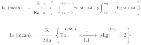
7. Using the simple expression for anode current of a triode Ia = K/Ra (Ea : µEg)
and transforming this for AC operations on the positive half cycle of applied anode volts we have:---
8. Deriving this in terms of RMS applied voltages and remembering that anode current flows only on the positive half cycle and will be read on a mean reading DC meter, we have:--
E.g. (DC) is the applied half sine wave DC as read on a mean reading DC voltmeter, K being a constant. The above relation holds equally well for screen grid of pentode valves, which would allow the general form
9. Thus with an applied RMS anode (and or screen) voltage equal to 1*1 x Va(DC) and mean value of half wave rectified bias voltage equal to 0*5 x VG (DC) then the valve will read a mean DC anode current equal to one half of the DC anode current taken from the static characteristics if Va (DC) and VG (DC) were applied DC test volts. This relationship holds for all practical purposes over the full characteristics and is the basis of operation of the VT160 enabling accurate testing of valves, at any point on their characteristic, with simple and small apparatus. This accuracy is just as necessary on the simple “go”/”no go” type of instrument as a complete characteristic meter, as it may be necessary to set the test point anywhere on the characteristic to correspond to required working condition. Further in the absence of any printed or predetermined test figure, it must be possible to determine test conditions directly from manufacturers published curves of data.
Basic circuitry
10. The principles of operation of the main function of the tester – the comparative testing of mutual conductance – lie in the application of anode, screen and heater voltages corresponding
8
to the working point of the valve and backing off to zero the standing anode current thus obtained. A small incremental bias is applied to the valve and the change in anode current thus obtained is a measure of the mutual conductance of the valve. The figure is then compared with the correct mutual conductance to give comparative goodness on a coloured scale.
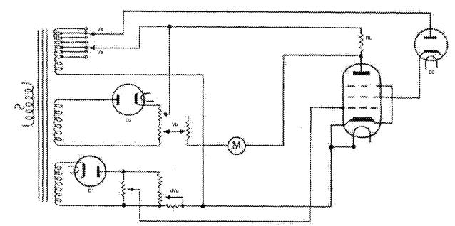
FIG. 1.
BASIC CIRCUIT FOR CHECKING OF MUTUAL CHARACTERISTICS
11. figure 1 shows the fundamental circuit used in this measurement. With a requisite electrode voltage applied to the valve, the half wave anode current causes a voltage drop in resistor RL, which is sufficiently low resistance not to influence the characteristics. This voltage is backed off by a voltage of similar form from the Control Vb. The voltage difference across the two arms of the bridge thus formed is shown on the DC millivoltmeter M. When this difference is zero, the voltage Vb is a measure of the anode current in RL (Ia = V/RL) and the control Vb is thus calibrated in mA anode current.
A small change in bias is then applied to the valve from control dVg which causes an increased voltage drop in RL which unbalances the bridge. This unbalance is shown on M and is a measure of the mutual conductance of the valve. For a deflection on M of RL millivolts then the mutual conductance of the valve in mA/V is 1(volts)/dVg. In practice the f.s.d. of M is 130% RL millivolts and the scale is zoned in three colours – green from 130% to 70% indicating a good value, white from 70% to 50% representing a failing valve, and red below 50% indicative of a reject. Thus the operating procedure after backing off the initial anode current is to set control dVg (calibrated in mA/V to a maximum of 20) to the rated mutual conductance and note the deflection on the coloured scale of M, to determine valve goodness.
9
12.This arrangement, which gives an incremental grid voltage inversely proportional to slope, avoids errors otherwise likely to occur on high slope valves which often exhibit marked curvature of characteristics.
13.The stopper diode D3 shown in the screen supply circuit in figure 1 is to prevent erroneous results, and possible valve overheating and damage, that can occur when testing certain beam tetrode valves with alternating anode and screen voltages.
14. As the applied electrode voltages approach zero during a portion of the operative cycle, the focusing of the electrode beam is to some extent upset with the result that the screen current decreases, and rapidly becomes negative. The rectifier, whilst presenting negligibly low forward impedance to normal screen current, by virtue of its high reverse impedance successfully prevents the flow of reverse screen current.
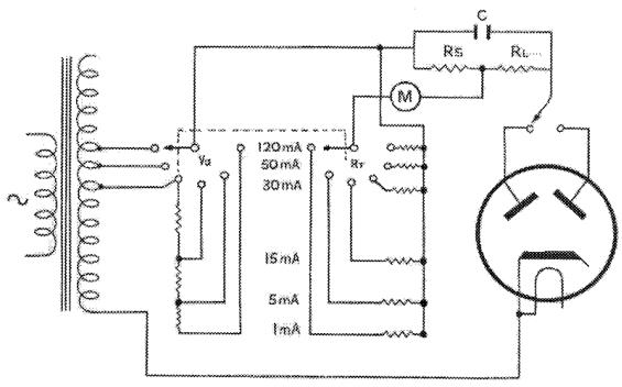
FIG. 2
BASIC CIRCUIT FOR THE TESTING OF RECTIFIERS AND SIGNAL DIODES.
15. Figure 2 shows the basic circuit of the rectifier test. The rectifier is loaded with a resistor RS + RL, and a reservoir capacitor C in parallel. Sinusoidal voltage Va is applied of sufficient magnitude to operate the rectifier on the linear portion of its characteristics, so that the combination should pass a rectified current equal to the maximum load current of the valve.
10
The millivoltmeter M measures the voltage developed across a proportion of the load RL and is scaled by the appropriate range resistor RT so that the rated current through the load will deflect M to the middle of the “good” zone of the scale. The proportionate deflection of the coloured scale donates the state of the valve as before. Switching of anode voltage meter range and load is ganged so that rectified currents of 1mA, 5mA, 15mA, 30mA, 60mA and 120mA per anode are available, each anode of a full wave rectifier being tested separately. The 1mA and 5mA ranges are suitable for signal diode testing.
FIG. 4
16. For the checking of inter-electrode insulation (figure 4) the unidirectional grid voltage Vg is applied through the meter M suitably loaded by a shunt(s) and high series resistor (R) across the electrode groups, between which the insulation is to be measured. Vg, S and R are such that the first meter indication is at 25MO, full scale of course representing a dead short. The meter is suitable scaled for direct reading between these limits. This test serves for heated continuity and insulation measurements between anode and all other electrodes strapped, and screen and all others with the valve cold. With heater volts applied, the normal cathode/heater test is made, whilst a further test of cathode and heater strapped/rest takes care of sagging grids or filaments of directly heated valves Since a short circuit deflection is, in fact, a measure of the grid voltage, this is used in checking of the setting of the main voltage if the instrument in position “Set ~”, in this condition a short is put on the insulation test circuit, and the mains selector is adjusted until the meter reads full scale deflection, at which point the grid voltage and therefore all other voltages working the instrument are correctly proportioned.
17. The full circuit (figure 3) shows how all the above combinations are incorporated in a single circuit, and selected by appropriate switch settings. Despite the full range of test voltages available and the comparative complexity of the circuit, the discreet use of ganged controls has reduced the operation to a simple and logical sequence.
11
18. Figure 5 shows in diagrammatic form the panel marking and it will be seen there from that in addition to the controls supplying the appropriate electrode voltages, only three controls are really involved in a measurement. The CIRCUIT SELECTOR rotates through the various insulation checks to position TEST, at which point the circuit is operative for mutual conductance testing by backing off with the ANODE CURRENT controls and by setting control SET mA/V, at which point the meter shows the valve goodness. Separate electrode systems of dual or multiple valves are measured by setting the ELECTRODE SELECTOR to A1 or A2. With this switch to D1 or D2 the circuit is ready for rectifier or signal diode testing, with the CIRCUIT SELECTOR at TEST. The selection of load current is made by rotating the anode current control (also separately scaled in rectifier load current) to the appropriate position, valve goodness being immediately shown on the same coloured meter scale.
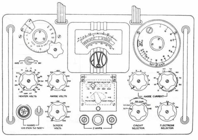
FIG. 5
19. The rotary control SET mA/V is of the spring return type , and once a test has been made, automatically returns to its start position at which point the measurement circuit is shunted to a safety condition. This if a subsequent is carelessly attempted with circuit wrongly set or if for instance a “gassy” valve is tested, this will be shown up before the circuit is put in a sensitive condition for mutual conductance testing and no damage will result to the instrument.
20. The final position of the CIRCUIT SELECTOR (market GAS) places the meter M, shunted as a micro-ammeter, in series with a resistor in the grid circuit of the valve being tested and allows the direct measurement of grid voltage in µA.
12
 Loading...