

Page 1

MK II
WORKING INSTRUCTIONS
AVO
AVOCET HOUSE, 92-96, VAUXHALL BRIDGE ROAD, LONDON,
ENGLAND
LIMITED
Page 2
THE
MODEL 8 UNIVERSAL
AVOMETER
Mk II
INSTRUCTIONS FOR USE
AVO
AVOCBT HOUSE, 92-96 VAUXHALL BRIDGE ROAD, LONDON, S.W.l.
Teleph one: V ictoria 3404 (9 lin es ) ENGLAND Tel egrams: Avocet, Sow est, London
LI M IT K I)
Page 3
FOREWORD
For more than a quarter of a century we have been engaged in the design and
manufacture of “ AVO ” Electrical Measuring Instruments. Throughout that time
we have consistently pioneered the design of modern multi-range instruments and
have kept abreast of, and catered for, the requirements o f the epoch-making develop
ments in the fields of radio and electronics.
The success of our steadfast policy of maintaining high standards of performance
in instruments of such wide versatility, and making such instruments available at
reasonable cost, is reflected in the great respect and genuine goodwill which “ AVO ”
products enjoy in every part of the world.
It has been gratifying to note the very large number o f instances where the satisfac
tion obtained from the performance of one of our instruments has led to the auto
matic choice of other instruments from the “ AVO ” range. This process, having
continued over a long period of years, has resulted in virtual standardisation on our
products by numerous Public Bodies, The Services, Railway Systems, and Post
Office and Telegraph Undertakings throughout the world.
Our designers have thereby been encouraged to ensure that new instruments or
accessories for inclusion in the “ AVO ” range fit in with existing “ AVO ” apparatus
and serve to extend the usefulness of instruments already in being. Thus, the user
who standardises on “ AVO ” products will seldom find himself short of essential
measuring equipment, for, by means of suitable accessories, his existing equipment
can often be adapted to most unusual demands.
It is with pleasure that we acknowledge that the unique position attained by
“ AVO ” is due in no small measure to the co-operation of so many users who
stimulate our Research and Development staffs from time to time with suggestions,
criticisms, and even requests for the production of entirely new instruments or
accessories. It is our desire to encourage and preserve this relationship between
those who use “ AVO ” instruments and those who are responsible for their design
and manufacture, and correspondence is therefore welcomed, whilst suggestions will
receive prompt and sympathetic consideration.
2
Page 4
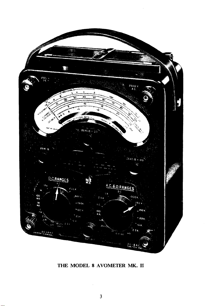
THE MODEL 8 AVOMETER MK. II
3
Page 5
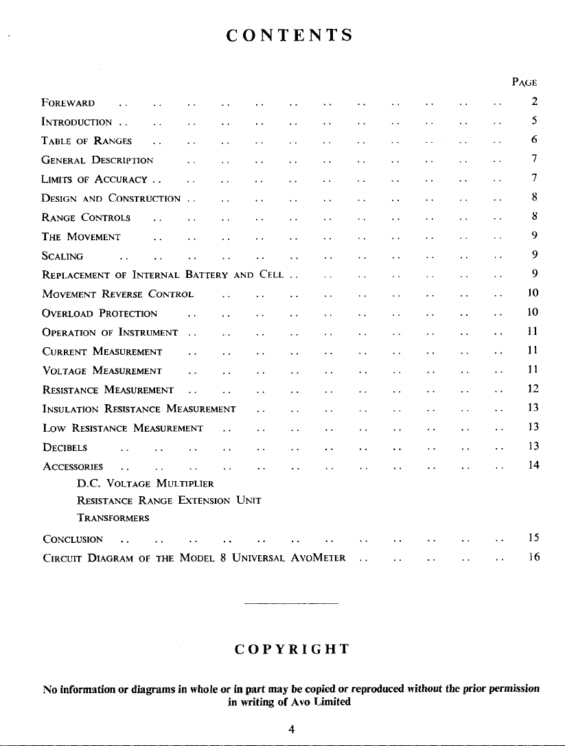
CONTENTS
F o r e w a r d
I n t r o d u c t i o n
T ab l e o f R a n g es
G e n e r a l D e s c r i p t i o n
L im i t s o f A c c u r a c y ..
D esi g n a n d C o n s t r u c tio n
R a n g e C o n t r o l s
T h e M o v em e n t
Sc a l in g
R e p l a c e m e n t o f I n t e r n a l B a t t e r y a n d C e l l
M o v e m e n t R e v e rs e C o n t r o l
O v e r lo a d P r o t e c t i o n
O p e r a t i o n o f In s t r u m e n t
C u r r e n t M e a s u re m e n t
V o lta g e M e a s u r e m e n t
R e s i s ta n c e M e a s u re m e n t
I n s u l a t i o n R e s i s ta n c e M e a s u re m e n t
Low R e s i s t a n c e M e a s u r e m e n t
D e c ib e l s
A c c es s o ri e s
D.C. V o l t a g e M u l t i p lie r
R e s is ta n c e R a n g e E x t e n s io n U n i t
T r a n s f o r m e r s
C o n c l u s i o n ......................................................................................................
C ir c u it D ia g r a m o f t h e M o d e l 8 U n iv e r s a l A v o M e t e r
P a ge
2
5
6
7
7
8
8
9
9
9
10
10
11
11
11
12
13
13
13
14
15
16
COPYRIGHT
No inform a ti o n or d ia g ra m s in whole or in pa r t m ay be copied or repro duced without th e p rior permi s s i o n
in writing of Avo Limited
4
Page 6
INTRODUCTION
Sin c e its con c eptio n in 1923, t he Av oMeter has m aint aine d a dist i nct l ead upon all
its co mp etitor s , and c an tod ay q u i te rig h t l y be t e rme d t he mos t popul ar instrumen t
of its type in t h e worl d , fo r in no other in strume nt can one f in d s uch a unique c ombi
natio n o f r anges and comp rehen sive aut om ati c over l oad p rot e ction, in addi t i on to
a high de gree of a c cura c y , reliabili t y and si mpl i c ity of u se .
M uch ti me an d tho ught is conti nually d evo ted b y ou r des i g n dep artment t o the
im prove ment of o ur pr oducts an d it is for the Ele ctronic Rad io and Te l evi s i on
En gine er that thi s new inst r ument ha s been primari l y pr o duc ed. The Mo de l 8
A vo Meter Mk. II has th e hi g h D . C. vo l tag e sensi t i vity of the H igh Re sist ance Avo-
Meter Mode l s 1 and 2, but in additi on, prov i s ion is mad e for t he me a sur e ment of
A . C. curr e n t. A fur th e r us e f ul fe ature which ha s b ee n incorpo r ated is a push button
change - ove r switch which enables the dir ectio n of the cur r e n t th rou gh the mo vin g
co i l to be revers e d , thus obvia t ing t he nece ssit y of changing lead s when wor kin g
with D. C. vo l tag es an d curre n t s whi ch m ay be e i t h e r positive or n egat i ve in res p e c t
to a bas i c te s t p osi t ion. The excellent qu alities of pre vious models in cludin g th e
“ AVO ” automati c cut - out h ave bee n re t a ined, an d w e ha v e gr e a t con fid enc e tha t
given a rea s onable amount o f care and att enti on, not forge t ting the removal of
exhausted batt e r i e s , thi s i nstrumen t will g i v e lastin g sat i s f a c tion .
Page 7

TABLE OF RANGES
D.C. Voltage D.C . Current A.C. Voltage
2,500 V. 10 A.
1,000 V.
1 A. 1,000 V. 2-5 A.
2,500 V. 10 A.
500 V.
250 V. 100 mA.
100 V.
25 V.
10 V.
10 mA.
1 mA.
250μΑ . 10 V.
2-5 V. 50μΑ.
250 V.
100 V. 100 mA.
25 V.
2-5 V.
Resistance
0—200 megohms—with external voltage
0—20 ,,
0—200,000 ohms
1· self-contained
0—2,000 ohms
0—2-5 ohms with external unit.
A.C. Current
1 A.
Page 8

The
Model 8 Universal AvoMeter
Mk II
WORKING INSTRUCTIONS
General Description
The meter is supplied complete with a pair of special rubber-covered leads which
are intended for attachment to the AvoMeter by means of its non-loss terminals.
The remote ends of the leads are fitted with spring clips, which may be interchanged
with either the push-on type prod or the “ AVO ” Long Reach Safety Clip, both o f
which are located upon the battery box cover of the instrument.
The “ AVO ” Long Reach Safety Clip has been introduced to enable connections
for test purposes to be made at what are normally inaccessible points on a chassis.
Examination of the safety clip will show that it is completely insulated with the
exception o f the jaws at one end, which can be opened by compressing the stem into
the body of the clip. Rigid connections to wiring can thus be made by this insulated
device in complicated wiring systems where other types of larger clip could not be
attached, or if fixed might cause short circuits.
All tests, except those on the 2,500V. ranges, make use of the pair of terminals at
the base of the instrument.
The meter is extremely simple to use, range selection in general being accomplished
by means of two switch knobs.
A clearly marked 5" scale has uniformly divided graduations to match 100 and 250
scale markings, and in addition there is an ohms scale and one for decibels. An
anti-parallax mirror permits readings o f the knife edge pointer to be made with great
precision.
Limits of Accuracy
Generally speaking, the highest percentage accuracy on current and voltage ranges
is obtainable at the upper end of the scale, but on resistance ranges it is better towards
the centre of the scale. In the case of voltage measurements, which are more
frequently taken than those of current, successive ranges have been closely chosen to
obviate the need for taking readings on very small deflections.
7
Page 9

The instrument will produce its highest accuracy when used face upwards, in
which position it has been calibrated.
D.C. Voltage. 2 % of indication between full-scale and half-scale deflection.
Below half-scale deflection, 1 % of the full-scale value.
D.C. Current. 1 % of full-scale value over effective range.
A.C. Current and Voltage. (25-2000 c/s.) 2-25 % of full-scale value over effective
range.
The definition of “ effective range ” set down in the British Standard Specification
89/1954 is as follows, when related to the AvoMeter:—
D.C.—from 0-1 o f scale-range to full-scale value.
A.C.—from 0-25 of scale-range to full-scale value.
It will be noted that with the exception of the D.C. voltage ranges, the instrument
meets the requirements laid down in Section 6 of the British Standard Specification
89/1954 for 5" (127mm.) scale-length Industrial Portable Instruments. In practice,
the Model 8 is well within the above limits, due to the great care taken in the manu
facture of its various components, and to the fine initial calibration.
Inasmuch as rectifier moving coil instruments give readings on “ A.C.” proportional
to the mean and not the R.M.S. value of the wave form with which they are presented,
they depend for their accuracy not only upon their initial calibration, but also upon
the maintenance of a sinusoidal wave form. Since the form factor (R.M.S. value
divided by mean value) of a sine wave is 1-11, this has been taken into account in
calibrating the meter which does, therefore, indicate R.M.S. values on the assumption
that the normal sine wave will be encountered. Generally speaking, considerable
wave form distortion can occur without appreciably affecting the form factor and
resulting accuracy of measurement, but the user should recognise the possibility of some
error when using distorted wave forms, squarish wave shapes producing high readings,
and peaky ones, low readings.
Design and Construction
The instrument consists of a moulded panel on the inside of which are mounted the
whole of the switching apparatus, resistances, shunts, transformer, rectifier, etc.,
together with the movement. The panel fits into a robust moulded case, the joint
being rendered completely dust proof, whilst a carrying strap is provided to facilitate
portability. The main switching is accomplished automatically by means o f two
knobs which indicate on the engraved panel, the range in use. These switches are
of generous and robust design, the contacts being arranged to “ make ” before
“ break ” on adjacent ranges; a feature which provides a factor of safety in use.
When the instrument is set for operation on D.C ., the moving coil is associated
with a universal shunt and series multipliers, whilst on A.C., a full-wave rectifier and
transformer are also introduced.
Range Controls
The left-hand knob provides all the D.C. current and voltage ranges (except 2,500V.)
and the right-hand knob the A.C. ranges (except 2,500V.) and also the resistance
ranges. These knobs are electrically interlocked so that D.C. readings can only be
made after the right-hand switch has been set to D.C., and the left-hand switch to
the range selected. A.C. readings call for the left-hand switch to be set for A.C.
(it must not be left at RESISTANCE) and the right-hand switch at the range required.
Resistance tests require the left-hand switch to be set to RESISTANCE and the right-
hand one to the desired range.
Page 10

I f the swit ches are inadve r t entl y left to act u al r a nges simu ltaneo usl y, there is no
cir c uit t hro ugh the meter , and it is the reby s a f e g uard e d a gainst acc i den t a l d ama ge
or mis l eading readings .
It is poss i ble to d e t e rmin e whe t her a s o urce is A.C. o r D.C., s i nce A.C. will n ot
pr odu ce pointer indic atio n wh en the meter is s e t for D.C. mea s uremen t . A s mall
point er indi cat i on, how ever, may res ult if D.C. c u r r e n t is pas s ed th rou gh an A. C.
ran g e , b ut no h a rm can be d one to the meter provided it is not at the sam e ti me
gr ossly ove rloade d.
The m ain ran ges are engr aved on th e pa nel a r oun d t h e switches, a n d arrow head s
on the kn ob s i ndi cat e t he a c t ual range selec t ed. In the cas e of volt age , su cces s ive
ra n ges are built up on th e ra tios of 2 : 1, 2-5 : 1 an d 4 : 1 , but in t he case of curre n t,
a w i de cover age has been c ho sen in s tead and the 10 : 1 r a t i o in ge neral is fo l l ow ed.
The 2,5 00V. ra nges A.C. an d D . C. are av aila ble by m ean s of the two s peci a l te rmin als
so ma r ked.
Ex t r eme ly w i de c ove r age in r esis t a nce ha s bee n achi e ved b y ha vin g a fund amental
ran g e as mar k ed on the scale, to gether wi th r ange s of X 100 and 100 to supplement
it. Befor e car r y i n g ou t resi s tan c e tes ts, the mete r shoul d be adjuste d f o r t he s t a t e of
the b a t t e r i es. It is m e rely ne cess ary to join th e le ads toge t her and a djust to zero in
th e fo l lowi ng se q uen ce: ohms x 1; ohms 100, f oll owed b y ohms x 100, u sing
in each c a s e th e adj uster t o mat ch th e range.
In ad diti on, a 200-m egohm ra nge mar ked “ INS ” is avail a ble, using an ex t e r n a l
D.C. v oltage so urce .
The Mo v e ment
The moving co il consi sts of an al umin i um form e r w ound w i t h copp e r w ir e and
su pplemente d with Co nst antan i n order to re d uce te mperatu r e error. It i s piv oted
on h a r dened a nd highl y polish ed ste el p i vots b etw een conic al sp r i ng- load ed j ew els,
an d swings in a gap ener gise d b y two powerf ully m agn etis ed a nd a ged ‘ Al co m ax ’
blocks asso cia t ed wit h mild st e e l pole pieces. Two pho s ph or bronze hai r spri ngs are
fitte d f or t h e pur pos e of con veying c u r rent to t h e movi ng co il, and to provide con tro l
ling t orq u e. A kn ife edge type of p oin ter i s fitt ed enabling very f in e re adings to be
ta ken , whilst the whole movement is pe r f e c t l y balan ced and re aso nably dampe d so
th at th e poi nte r qui ckl y co mes to rest.
Sc a l i ng
T he sca l e p l a te has thr e e main sets of m arkings, e ach of approxima tel y 5" lengt h ,
th e o utermost being for r esistan c e mea s ure ment and is marked 0- 200,00 0 ohms.
The s econd is for cu r r e nt and vol tag e ( bot h A . C. and D.C.) an d is ma rked 0-10 0,
with div i sio ns a pprox i ma t ely l j mm. apart. The third sca le , cal ibrat e d 0 -2 50 , has
50 d i vis i ons, a nd is s o us e d fo r cu r r e nt an d vol t age measur ements . In addition, t h e r e
is a d ecibel scale mar k e d from —15 dB . to +15 dB ., which ca n b e u sed w i t h any of
th e A.C.r anges .
Rep l a ce ment of Internal Ba t t e r y and Cell
In sid e the c ove r , unde r th e car r ying s t r a p i s m ounte d a 15V. bat t e r y an d a HV.
cell. Thes e batterie s should be exam i ned f rom ti me to time to en s ure that t h e
electrolyte is n ot leaking and damagi ng the in s t r u ment . Th i s con dit ion will ge nerally
oc cur only when th e ce lls are ne a r l y e x hauste d. If it i s know n that th e mete r is goin g
to st a nd unu sed f or several mo nths, it is prefe r a ble that th ese batt e r i es shou ld be
re mo ved to pre v ent po ssible da mage.
9
Page 11

W hen rep l a c i ng batt e ries , the 1|V. c ell and the 15V. ba t t e r y must be i n serted w i t h
the po les to m a tc h the m arkings of polar i ty in sid e th e bat t e r y box .
Rep la c e m e n ts : 1-5V. cell, 1 f" di a . x2g ", s uch as E v e r Ready (o r ov erse a s, Ber e c ) U. 2 .
Mo v e ment Reve rse Con tr ol
It som etimes h appens t hat D.C. vol t ages ma y b e req u ired both posit i ve and negat i v e
to a re fe re n c e p oin t , or th e dir e ctio n of flow m ay be re v er s ed. In o r d e r to s i mp l i f y
the m a tt e r of lea d alt e rati on, a mo vement revers e pre s s but t o n ( RE V. M.C.) is
pro v i d e d. It s hou l d b e no t e d th a t th e p olari t y ma r ked o n the te rminals is for no r mal
use and does n o t a pply whe n the button is p r es s e d .
Over lo ad Pro te c t io n
Apar t fro m the abil i t y to do its j ob , one of the most a t tr activ e featu r e s o f th e
ins trument is the provi sio n of an autom atic cut -out which g i ves a very h i gh de g r ee o f
ov erload p rot e ction to the whole of the instr u men t . The i nco rpo rat i on of thi s device
wil l be fou nd to be of part i c u l a r valu e wh en co nd uct ing experi men t al wor k, for it
imp a r ts t o the us e r t he feeling of menta l ease and co nfid enc e. When condu cting
experimen t a l wor k with con ventional movin g c oil me t ers, th ese ca n be ea sily ru ined
by inadverte ntly app l i ed ov erloads, whereas the AvoMe t er is so we l l pr otected tha t
it c a n wit hstand consi derab l e mishan dling.
If a n o ver l o ad is a ppl ied to t he meter , the cut-out knob sp r i n g s f rom its nor mal
position in t h e pa nel, th us breaking the m a i n circu it, a nd this knob has only t o be
de pres s ed to ren der the i nstrument again rea d y for use. I t is im p ortant to note t hat
the cut -out sho uld n e ver b e rese t wh en the ins t rumen t is co nnect ed to an e x t e r nal
circu it, w h ilst t h e f ault which ca used t he over l oad sh oul d be re ct ifie d befo re the mete r
is re c onnected.
The m ech anism is br ought into o peration by th e moving coi l coming int o c ontac t
wit h a trig g e r ju st beyond its f ull-scal e positi on. There is, in additi on, a sec ond
release a t the z ero end, so t hat t he c ut- out i s tr i p ped if the meter is o ver loaded in reverse .
A l though the ov e rlo ad m e chani s m gives al mo st com ple t e prote ction to the met e r ,
it ca nn ot be gu aranteed to fulfil co mpletel y its function in t he v ery wor s t cas es of
misuse , such as th e mai ns bei ng connect ed acr oss the me t er when s et t o a c u rr e n t
rang e . It shoul d be no ted th at m ech a nical shock to the in s t rum ent will s om etime s
trip the cut- out me cha nis m. The c ut- out shoul d be rese t , usin g direct pr e s s ure an d
wi t hout twi s t i ng the bu tto n, the ins t rum ent lyi ng face upward s .
15V. battery , 1 ;,ι2 " χ |" χ l i" , suc h as Ever Re ady B. 121.
WARNING
Special care must be taken when using the instrument to service television receivers
or other apparatus emplo ying condensers of large capacity, for the inclusion o f such
components in a circuit may mean that ver y h ea vy p e a k currents may flow when the
apparatus is switched on. Such surges produce a pea ky wave f orm , and although these
pea ks are of only a few milliseconds duration, th ey may , never-the-less, puncture the
instrument rectifier. It is impossible to g u a r d against this cause of damage by means
of any form of cut-out mechanism, but instruments manufactured since July 1 95 4 have
been fit ted with a surge suppression rectifier (SAI) across the main rectifier, to give the
maximum protectio n which can be devised.
1 0
Page 12

OPERATION OF INSTRUMENT
The me t e r i s int end e d f or use ho rizont ally . Should it h app e n by any ch anc e that
the pointe r i s n ot on zero, it ma y be so set by means of t he s c r ew head on t he p a nel.
The lea ds f itt e d wi t h p rod s or cli ps, as re q u ired, shou l d be co nnected to t he l owe r
pai r of me ter ter minals in all c ase s e xcept w hen m e asur i ng volt ages o ver 1,0 0 0 V .
(se e n e x t para g r a ph).
W hen me a sur i ng cur r ent or volt age , en sure tha t the ins t rum ent is s et to match the
ty pe of s o urc e t o be me asur ed (e it her A.C. or D. C. ) an d t hen ch oose a suita ble r a nge
be fore connecting up t o the c i r c uit und e r test . Whe n in r eas on abl e doubt, al way s
sw i t c h to t he h i ghe s t ra nge a n d wo rk d ownw ard s , there being n o nec essi t y to dis connect
the le ads as th e s witc h posi tion is chang e d. Do not, however, switch off by rotating
either of the knobs to a blank position. If the volta ge should exc eed 1, 0 00V. , t h e
ins t r ument should be set t o m e a s ure 1,00 0 V . as desc r i bed above, but the neg a t i v e
lead s hould be trans fe r r ed to the app ropriat e 2,5 00V. t e r minal .
The ins t rum ent is flash te s t ed at 6, 000 V. A.C. , bu t s hould the m e t er be used wi t h
ac c ess o ries o n circuits in exces s of 2,5 00V., it s hould be kept at t h e low p ote ntial end
of th e c i r c u i t (near ea r t h p ote ntial) . If this pro c edur e cannot be adopted o t h er
su itabl e saf e guards must be applie d.
C URRE NT M E ASURE M E NT
T o m easu r e cu r r e n t, the instr ument shoul d be set to a su i t a ble A.C. o r D.C. rang e,
an d then conne cte d in serie s with t h e appar atus to be tes t ed.
Gene r ally s peaking , the pow er abso r bed in t he instru men t is neglig i ble, but in cases
of low v oltage hea v y curr e n t circui t s , the inc l usion of a mete r may reduc e the cu rr e n t
ap p reciably below the valu e which wo uld ot herwise prev ai l. The po t enti al d r op at
the met e r te r minals is in the o rder of | V. on all D.C. ranges , excep t the 5 0 micro amp
range whi c h has a drop of 125 m i l l i - volts. In the cas e of A . C., it is le s s tha n }V. on
all rang e s .
Standard meter l eads have a res i stanc e of 0 - 02 oh ms per pair.
In c e r tain cas es, care s hould be tak e n to ens u r e t h at the cir cuit is “ dea d ” b e fo r e
br eak i ng i nto it to make curren t mea s uremen t s .
V OLT AGE MEAS UREMENT S
W hen me a s uring v olta ge, it is ne cess ary to s et the appr o priate r a nge of “ A.C .” or
“ D.C. ” an d c on nec t t he leads across the so urce o f vo l tag e to be mea s ured . I f the
ex pec ted mag n i tud e of t he vol tag e is within t h e range of t h e meter, but it s act u a l
val ue is unknown, set t he in s t rument to its highe st ra n g e , conne ct u p an d if below
1,00 0 V. rotat e the app rop r i ate selec tor switc h, d ecre asing the rang e s step by step,
until t he most s uitable ran ge ha s be en sel e cted. Great c a r e mus t be exerci s ed when
m aki ng conn e ction s to a live circ u i t , a nd the pro c edu r e should be en t irely avoided if
possi ble .
On D.C. ra nges , the m e t er consu me s on l y 50 microa mp s at ful l s c ale defle c t ion,
th i s se n s i t i v i t y co rre s pondi ng to 2 0,0 00 ohm s per volt. In t h e case of A.C. ra n g e s
fr om 100V. upwards , full sc a l e def l ecti on is obta i ned w i th a co ns umption of 1mA .
(1 , 000 ohm s pe r vo l t ) . The 25V . , 10V ., and 2 -5 V . A.C. ranges co nsum e 4, 10 an d
11
Page 13

40 mA. respectiv ely at full sc a l e def l e ction. The m eter main tains a hig h de g r e e of
acc urac y f or a udi o f r e quency tests up to 10 kc/s on range s up to 25 0 V. A.C.
Whils t discu ssing the pro blem o f me asur i ng v oltage , it wou l d b e wel l to dr a w
att ent i o n to the f a ct t hat in ce r t a i n cir c u i t s wher e the cur r ent is limit e d be cause o f the
pre s e nce of a resista nce bet wee n t h e sco u rce a n d the p oint at w hich a me asurem ent
is to b e mad e , it is pos sib l e f or the actua l v oltage to be h i g her n o rmally tha n when the
met e r is c onnected . All cu r r e n t cons umin g vo l t met e rs, howe ver sens itive, draw
curr e n t to v a r ying de g r ees from th e circuit under test, thus caus i ng a higher vo l ts
dro p in th e r esist ances mentione d, and t h ereb y c aus ing th e vol t age t o fall at t he po i nt
o f me a s urement .
Owing t o t h e hi gh sens itiv i t y of the Mo del 8 on its D.C. range s , th i s effe c t is un l i k ely
to be of i mport anc e exce pt in a v e r y f e w instanc e s . A pra ct i c a l ex ample o f whe r e it
might b e take n i nto account is in the m e asur eme nt o f E HT volt age on a te lev i sio n
set or th e tap ping on a po ten t i al di v i d e r , whe r e t he re s is tanc e s ar e s o hi gh as to be
co mp ara ble with th e res istan ce of th e mete r on t he ra n g e in use. It is gene rally
po ssible to use a m e t e r on a h i g her ra n ge th a n abso l ute ly n e cessar y , and in s uch a
case the hi g her met er resis t ance caus es less d istur bance t h an wou ld ot herwis e be the
case. At the same ti me adequate poi n ter de f l ecti o n for reas ona ble a c cura c y sho uld
be attained.
Wh e n it is essentia l t o ob t a i n an acc u r ate i ndicati on of t h e v olta ge developed across
a h i g h resist a nce it is sometimes prefe r a ble to ins e r t the meter in series w i th it, and to
measure t h e curren t fl o wing. The re adin g gi ven upon th e meter , in m i l l i amps, multi
plied by the va lue of the resis t ance in thousa nd s of ohm s, w i l l g i ve th e dev elo ped
vol t age.
R ESIST ANCE MEAS UREMENT
The r e are three se l f -co nta i ned ranges cover i ng fro m 0-5 ohms to 20 megohms, a nd
pr ovision is a lso made f o r both upw ard and d ow nw ard extens i on of the se limits.
Th e sel f - con t ained ranges mak e u s e of t h e usu a l se r ie s cir c u it , and su c ces s i ve ran g e s
are o n 100 : 1 r a t io , which permits of very w i de c ov era ge wi t h th r ee rang e s .
On r esist a nce ra nges, the m e t e r m ust not mer e l y star t f r om its normal in stru men t
zer o, bu t mus t h ave, in a ddi t i on, a r e s i s t ance zero corr espon din g t o the full scal e
deflect i o n of t h e met e r . Befor e carry i n g out test s fo r resis t ance a check and , if
nec e s sa r y , adju s t ment s hould be carri ed o ut to en s u r e that wh en the leads are joi ne d
toget h er the met e r actu a l l y i ndi c ates zer o ohms, i r r e s p e c t i v e o f th e c on diti on o f th e
batte r y ( with i n the l i mits of ad justment ) . The method o f adjustment is descr i bed later.
Owin g to t h e nat u r e of the s cale, it is not e asy to defin e the accu racy , b u t it sh oul d
be within 3% of t he readi ng a bout cen t re sc a l e, inc r easi ng up to abo ut 10% of t h e
indicatio n a rou nd de f l e ctio ns corres pondi ng to 10% and 90% of f ull sc a l e defl e ction.
Re sist a nce test sh oul d never be carr i ed o ut on c omp onents which are already
carr y i n g cur r en t .
On th r e e r ange s whic h uti l is e the int e r nal s our c e of vo lta ge, it sh oul d be remem
bere d that a p ositiv e pot entia l appea rs at th e neg ativ e terminal of the in s t rum ent
when se t f or res i s t ance tests . This fact ma y b e imp ort ant beca use the re s i s t ance of
som e com po nents va r i e s ac cor din g to th e directi on of the curre n t thr ough t hem, and
rea dings , th e r efor e , d e pend upon the d i r ecti on i n which th e test voltage is a ppl i e d,
qui t e a p a r t fro m its magnitud e. Such ca ses inc l ude electr olytic conde nse rs and rectif iers .
When m easuring the leak age resi s t ance of an e l ectrolytic c ondenser, the negati v e
lead fro m the m e t er should be connecte d to th e pos itive te rminal o f th e con den s er,
and the o hms x 1 00 ra nge empl oye d.
12
Page 14

Be f ore ma kin g res i s t a nce t e sts t h e po i nte r shoul d be adj u s te d to z ero in the fo l lowin g
se que nce:—
1. S e t l eft- han d switc h at “ RESIS TANCE
2. Join lea d s tog e t her.
3. On t h e Ω r a n g e , ad just to z ero by means of the kn ob mar ked “ ZE RO Ω ”.
4. On the “ Ω + 100 ” rang e, adju s t to zero b y mea ns of the knob marke d
“ Z ERO Ω -f- 10 0”.
5. On t he “ Ω χ 10 0 ” range, adj u s t to zero by mea n s of the k n ob mark e d
“ ZER O Ω χ 100” .
T o te s t a re s is t a nce, set the right-h a nd switc h at th e rang e r e q u ired, the lea ds being
co nn e cte d a c ross the unknown co mponent.
Re sistance is re ad dire c tly on the “ Ω ” ran g e, bu t i ndi c ations sh oul d b e divid e d
or multip l i e d b y 100 on the ot her tw o rang es .
If on joining the le ads t oge t her it is imposs i ble t o obta i n zero ohms settin g, o r i f
fur th e r more the po i nter position will not rem a i n co nst ant, b u t f a ll s st e a dily, the
inte r n a l b attery or ce l l concerned should b e r e p l a c e d. It is i mpo rtant that a discharged
unit should n o t be left i n th e ins t r ume nt, sinc e the ele ctrolyt e might see p thro u g h
and caus e damage to the mete r.
NOTE. It ca n so hap pen t h at a 15- v olt bat t e ry m ay ag e in such a mann e r that
al t houg h it ind i c ates a potential o f 15 volt s , its inter n a l res istan c e has incr e a s e d so
mu c h th at s om e lo ss o f acc u racy can oc cur o n the high resi s t a n c e ran g e (Ω χ 100).
If the ba tt e r y has b een in use for some time , or i f e r ror s are suspecte d on the high
res i s t a nce ran g e , it is w orth whi l e removing t h e ba tt e r y and chec kin g its short c i rc u it
curr e n t on the 1 0 0 mA. D.C. rang e . If the batte r y f ails to give a re a ding gr e at e r tha n
5mA. it sh oul d be dis c a r d e d.
INSUL ATI ON RE SISTA NCE M EAS UREMEN T
T wo course s are open , t he first m e r ely callin g for a ba t t e r y or ot h er so urce of
D. C. v oltage in t h e o rder of 130V. t o 160V. The left - h a nd s witc h shou l d be set at
“ R ESISTA NCE ” wi th t h e ri g ht-h a nd sw it ch at “ IN S ” and th e met er lea ds sho uld
be c onnecte d to t h e batt e r y . The point er s hould be br o ugh t to ze r o o n the ohm s
scale by m e ans of th e adjus te r mark e d “ ZER O Ω x 1 0 0 ”. T o test , c onnect the
unknown re s i s t a nce in se r ies with the mete r and its va lue wil l be th a t sho wn on the
ohm s sca le mult i plied by 1,00 0. R esis t anc es u p to 20 0 megohms ca n, t h e r e f o r e , be
read on th i s range.
The al t e r n a t i v e me thod makes use o f th e “ Mo de l 8 Res i s tan ce R ang e Ex t ensi on
U nit,” desc ribed later.
L OW RE SI STA NCE MEA SURE M ENT
The meter sett ing mar ked L. R. is for use with the Mo de l 8 Resist anc e Range
Ex t ensi on Unit. The me thod of u s e is de s c r i bed i n th e sec t i on upon a c cesso ries.
DEC IBEL S
The decib el sca l e can be used with any o f t he A. C. current o r v oltage ra n g e s. It
has a l oga rith mic scal e shap e and is useful in s o far that it giv es a measuremen t
closely re l a t e d to the im pre s sion of au r a l intensi t y in sound re pro ductio n a p p aratu s .
A differ e n c e of o ne de cibe l is about t he mini mu m diffe r e n c e whi ch can b e appr e c i a t e d
when comparing two int e nsiti es. For con venience, the sc a l e is mar ked in dec i b els
13
Page 15

bot h p osit i ve and ne gati v e fr om a re f er e n c e poi nt. The diff e r e n c e in level be t ween a
neg ativ e value on the dB. sca l e a n d a pos i t i ve one is th e sum of the t wo, i.e. t he d i f fe r
en c e be tween —5 d B . and + 6 d B. is 5 + 6 = 11 dB.
It will be ap prec i ated th a t when changing fro m one curre n t or vo l tag e r a nge to
the next hig h e r , t he poin t er in dication will fa l l , alt hough input is kept cons t ant . For
a cu r r ent or vol t age ra nge ra t i o of 2\ : 1 t h is co rre spo nds t o a re d ucti o n o f 8 in the
ind icat i o n o n the d B . sca l e. It fo llo ws, th e r efore , tha t 8 s hould b e a d ded to th e
read i n g eve r y time a n i ncre a s e of 24 ti mes tak es pla ce on th e ra n g e. In t he sam e way,
12 should b e ad ded fo r an in c r e a s e of 4 tim es on the ran ge, or 8 + 12 =2 0 d B . f o r
an incr ease of 2 | x 4 = 10 time s in the r a n g e r a t io .
The fo l l owing mi ght serv e as an e xample: Suppo se that t h e meter is c o nnected on
the 25V. A.C. range acr oss the pri mary of an o utp ut t r a nsfo r mer and th a t a reading
of + 9 d B . is indica t ed (cor r esp ond i ng to 12-5V. o n thi s ran g e ) . If n ow the out put
inc r e a s e s to say 40 vo l t s , nec essi t atin g a c hange to the 100V. A. C. ra n ge, the point e r
will i ndic a te 4 7 on t h e dB . s c ale .
Th e 4 : 1 increase in the vol t age ran ge c alls for an ad dition of 12 to th e dB. in dica
tio n, s o tha t its true value re p rese n t s | 19 d B . Th e i n c r e a se ove r the o r i g i n al reading
is 1 9 -9 = 10 dB.
ACCESSORIES
D. C . Vo l tage Multipliers
1 OkV D. C. Multiplier
A lOkV. D . C. Multipl i er h a s been de veloped mai nly to en able t e s t s t o be car ri ed
ou t in te l evision c i r cuits . The mult iplie r s hould b e c onnec ted in ser ie s w ith the meter
on its 2 ,500V. D.C. range , in which s t a te max i mu m c onsumpti on on me a s ure ment
ca nnot excee d 50 mi cro a mp s , and m ay be co nsiderab l y less . It is recom mended
tha t th e m e t er is kept as n e a r e arth p otential as p ossibl e , a nd the mult i plier use d at
th e high p ote ntial e nd, e. g., when m e asu r i ng an E.H.T. voltage w h ere t he neg ativ e
line is ea r t h y , the mu l t i plie r s hould be c onnec t ed be twe e n the po i nt o f po s i t i ve
po tenti a l an d the positive te r mina l of th e me te r , th e nega ti v e lea d bein g connected
to the ter minal mar ked 2, 500V. D.C.—. We do not reco mm end , in suc h ca ses ,
co nn e cting t he multiplie r t o t h e 2,500V . D .C . — ter minal and p ress i ng t he movi ng coil
reverse button, notwith sta ndi ng t he fact tha t the meter is at the e a rthy e nd of the
circuit .
25kV D.C. M u ltiplier
A 25 kV. D.C. Multi plie r is availa ble for use in se r i e s wit h the m e te r set t o its 10V.
D. C. range, rea d i ngs being made dire c t in kV on th e 0-25 scale . It is most i mporta nt
to ensure t hat the met e r i s ke pt in the ear t h y end of t h e circ u it an d th e mul t i plier
co nnected to ei t her th e positi ve or negati v e terminal whichev e r i s at hig h potenti al.
Th i s m eth od of connectio n t o ge t forw ard poi n ter indicat i on wit h the met e r ea r t h y
is r eco mm end ed a s we do n ot thin k it de s i r able to use the moving coil reve r se bu t t on
wh en mea sur i ng h i gh vol t age.
In gen e r a l w e reco mmend that nei t her t he mete r , mu ltipl i e r no r le ads are ha n dled
whilst high voltage te s ts are i n progres s, a nd a s pecial le a d is prov i ded wi th th e
mu l t i plie r for c on ne ction to the hig h pote ntial p oint .
NOTE. The 2, 500 V D. C. ra nge i s not em ploye d w hen usin g thi s mult iplier.
14
Page 16

Res i st a nce R a n g e E x t e n s i o n Unit
This devi c e enable s t h e me t er to be used for bot h high an d low r e s i s t a nce me a s ure
ments . It is c om ple te with bat t e r i e s (except in som e in s tan c es) and sw itch i ng to
fac i l i t ate te s t s . T he d e vice should be connec ted to the lower term i nals on th e meter.
F or hi gh res i s t ance the m e t e r is s e t to the “ Ω χ 100 ” posi tio n, th e U nit swi t ch
at the “ S ET ” posi tion and the unknown resi s t ance should then b e co nnect ed to the
“ High ” term inals. Adju stm ent to ful l scale defl e c t i on sho uld be perf orm ed by
m eans of th e “ ZER O Ω x 100 ” kno b. The Uni t sw i t ch s ho uld then b e ro tated to
“ TES T ”, an d th e re adin g o n the o hms sc a l e n oted . I t s va l u e is th at sh ow n m ulti
pl i ed by 1 , 0 0 0 c orr e spond ing t o a r a nge of 200 me gohms.
On t he low ran g e t he Unit swi t ch shoul d be plac ed at “ SET ” , t he unknown
res i s t ance conn ected to the “ Lo w ” ter minals and ad j u s t men t to fu ll sc a l e de f lectio n
carr i ed out by me ans of th e “ Z ERO Ω ” knob. The Unit switch sho uld the n be
m oved to p osi tion marked “ T EST ” an d the p o i nter de flec t i on on a uniformly
div i ded sca l e noted. Ful l scal e defl e ctio n co rre s pon ds to 2' ohms.
In orde r t o avo i d di s char ging the batt e ries, imme dia t ely test s ha v e be e n comple t ed
the t est lead s a nd resist a n ce s hould be re mo ved f rom the unit , its s wit c h set to the
“ low set ” posit ion, a nd t he unit disconnec t ed fro m the meter .
Rep la c e ments : 1-5V. Ce l l —I f " dia. x2f", su c h as E v er R eady (o r ove rsea s , Ber e c ) U.2
F our 30V. batte r i es — l 312" xf" x 2^ " , such as E v er Ready B . 123.
Transfor me rs
Transf o rme r s as used on the Mo de l 7 Av oMeter are e qually appli cab l e f o r use w i t h
th e M od el 8, when se t t o 10 0mA . A.C . It is nec e s sary to connect th e meter u p t o t h e
se c ond ary of t h e transfo rme r bef ore c u r r e n t is p ass e d t hro ugh the pr imary, and care
shou ld be t a ken t hat the cut - out is in pos i tio n. If this co urs e is no t fo llo we d, quite a
co nsiderable vo l t age will app ear at t he s econda ry te r minals, if curr e n t passes t hrough
the p rimary. T rans f orm e r s for 50 amp. , 100 am p., 200 amp. and 400 amp. are
available.
CONCLUSION
Du e to the high ope rati onal sta n dards ma i ntai ned t hroughout our org anisati on,
an d the close limits w ith i n whi ch w e w ork , b r e akdowns are com par ativ ely rare, and
can of ten b e tr a c e d to transi t d amage or car e l e s s handli ng, for w hic h t he Company
ca nn ot be h e l d re spo nsib l e. Shoul d you at an y t i me hav e to retur n your instr ume n t
to the C om pany f or repair , pack it carefully and enc lose a note i nfo r ming our engin eers
of the f ault s w h ich yo u h ave fo und .
E. & Ο. E.
Page 17

A C. SWITCH CAM .
OUTE R CAM.
L.R .. Λ -t- IOO i aV,' ° £ f ! J
AND S I
a .c . r anges ] 5 c,S lS 5 S 5
ALL OTHER J
POSITIONS I
.ν5 . Λχιοο{ ( 9 0 Ρ | ν
Sl-rlO O { ^ c l o sed
I die OPEN
ALL f a ^CLOSED
\ de.C LOSED
ab C LOSED
ac .O P E N
d e OPEN
JHNE B.QAM·
όόόαόόόόόόόό όόόό
INS. \ & / · L.R. / 250V. \ 25V. \ 2 5V. / ΙΑ. / IOA.
flX lOO lflrlO O IOOOV. IOOV. IOV. lOOmA . 2 5A.
A .C . SWITCH
D.C. + A A.C. COMMON. D .C -4 A.C. SWITCH RANGES.
CIRCUIT DIAGRAM OF THE MODEL 8 AVOMETER MK. II
O.C.
A.C.
RES ISTA NCE
I lOmA / 2 5 0 5 0 i k
lOOmA. 1mA. yuA. /jA .
0 9
~ v
D.C. SWITCH
2 5V. / 25V. / 250V. \
IOV. IOOV. SOOV.
 Loading...