

Page 1
Mega Deals on Meters Great prices on insulation meters Buy now and save mega bucks!
www.testandtagsupplies.com
www.deadweighttesters.co
Deadweight Testers Hydraulic & pneumatic, high & low pressure. High quality as standard.
Hach Australia Australian Hach Distributor Hach Preferred Process Distributor www.pryde.com.au
Restoration and repair to vintage AVO Valve / tube tester
early valve tube technology,
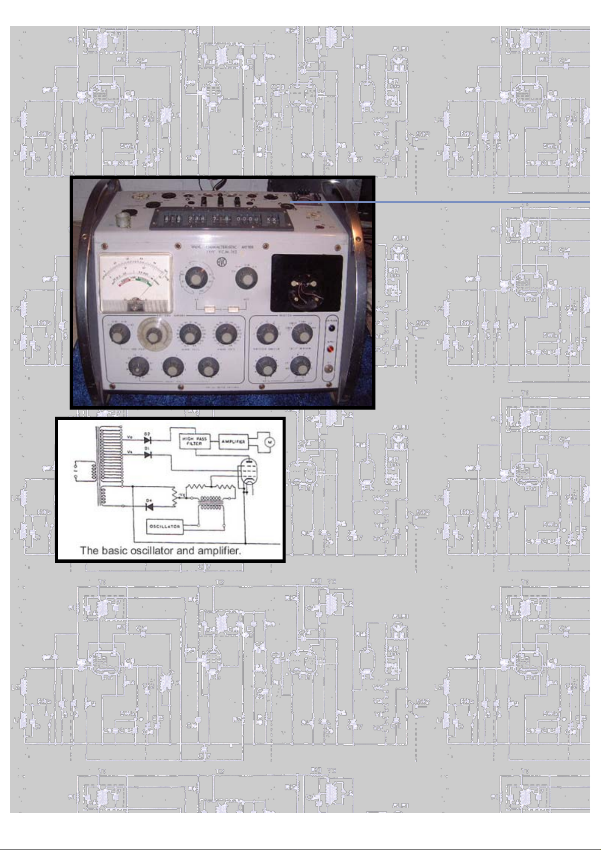
The AVO 163 Valve Tube characteristic meter
V.C.M.
Just purchased on ebay, going cheap as one of the meters is missing .
I am going to fit an alternative meter and match it to the machine
using an Op Amp. The design for this comes from a fellow member of
the B.V.W.S.
successfully used the method on Mk 1s and 3s. The avo unit is
superbly engineered, I would love to know its price when new. The
switching design has been changed from all the previous models, with
a much smoother action, and solid state technology has been
introduced. This has greatly simplified the testing method with no
need to do the backing off. it is all carried out and continuously
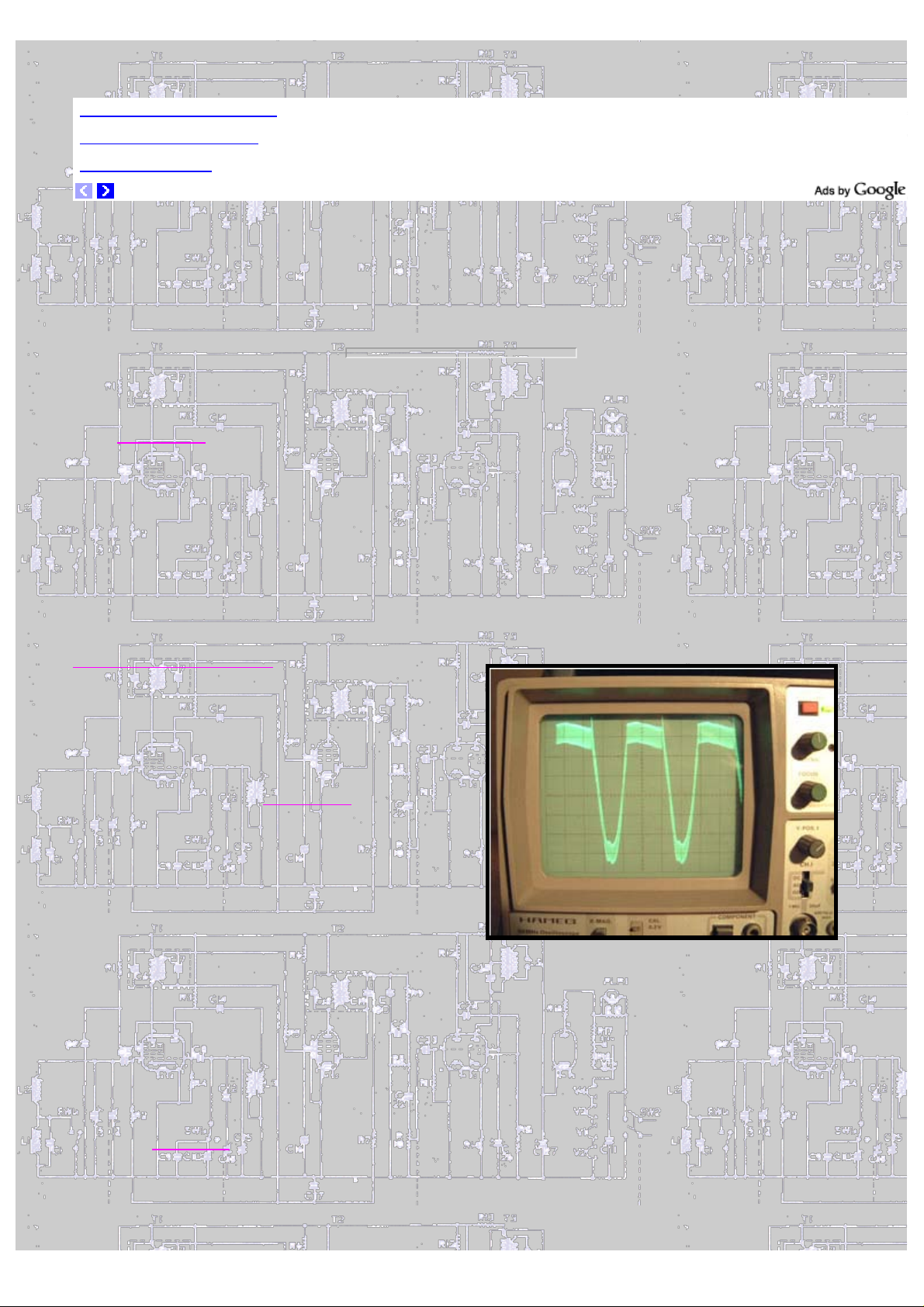
monitored with the Right hand meter. A small signal about 20 K/hz is
superimposed on the rectified A.C. fed to the control grid, the
signal is sampled at the anode and is displayed on the G/M meter. You
can just see the 20 k/hz signal on the scope display.
Gary Tempest it uses a 8 pin I.C. TL071 (741) Gary has
After giving the unit the once over I have found by using the
standardized valve
instrument is over reading about
25% on the 100 m/a scale and 10 %
on the 30 m/a scale, the 10 and 3
seem ok. The left - hand meter has
proven to be faulty, with an
internal resistance of 2160ohms. It
should be 2400 ohms. I have had a
word with fellow B.V.W.S.
Denis Tabor, Denis tells me that
Avo brought out Taylor meters in
the late 60s and the meters
installed in these instruments are
in fact made by Taylor instruments
Ltd, and were not that good.
Nothing like the quality of the
Avos in earlier testers. Denis is a
font of all knowledge on the
subject of valve / tube testers of all makes worldwide and is always
keen to help.
Checking the shunt resistors R11, R12, 2.4 and 8.02 ohms they are
slightly high, The 2.4 has risen to 2.7 this will make a big
difference to the readings. These resistors were Probably damaged due
to incorrect switch settings, and serious overloads during its 40
years of service. It looks as if I will have to buy 2 meters. One
problem encountered is removing the control knobs they have every
small Allen key screws 2 on each knob . One supplier of these small
keys is C.P.C.
is a small order charge.
that the
member
Part number TLO3270 and priced at £1.50 However there
With the Mains disconnected.
Using a very accurate test meter, (fluke etc) the value of the shunt
resistors can be checked in situ, any out of tolerance can be
Page 2
replaced using 1% High stability types. The meter characteristics can
be checked using ohms law : - At full - scale deflection the meter under
test should have 120 millivolts across its terminals. Disconnect the
wiring from the meter and feed in a tiny current from a 1.5 - volt
battery cell, via a 2.5 meg ohm potentiometer. Set the wiper to mid
point and then carefully turn until at full - scale deflection, then
measure the volts across the meter, check full scale again. 120
millivolts should show on the fluke. A good way around the problem,
if both meters were present, would be to swap over the faulty meters
left to right, and swap the scales over. It will be certain the RH
meter will not have had any overloads.
See below the replacement meter. A good quality meter, 100 micro amps
full scale, salvaged from an old Dymar distortian meter. The op amp
matches the old meter impendence to the new one . So with exactly 120
m/volts going in, the op amp gain is set so the new meter reads
exactly full scale . I have left it on test for hours, heated and
cooled it, and it remains remarkably stable. Next job is to fit it
into the Tester.
Page 3

Close up of the 741 chip,TL071 Op amp. Showing the set Zero and the
gain controls
Avo instrument dust covers, all models, made to
measure. If you are interested drop us a line.
Page 4

Continued on the next page.
Back to Home page
 Loading...