

Page 1
USER MANUAL
AvMap GEOSAT 4 ALL
AvMap GEOSAT 4 CAMP
AvMap GEOSAT 4 TRUCK
Ver. 0.2
Page 2

Page 3

Dear Customer,
Congratulations on choosing AvMap Geosat 4 ALL / AvMap
Geosat 4 CAMP / AvMap Geosat 4 TRUCK navigator!
With Geosat on board you will be able to
- receive your GPS position and view it on detailed Tele
Atlas mapping
- set your destination and be guided by written prompts
and voice instructions
- plan a complex trip
- obtain a list of nearby points of interest
- stroke your favourite location as marks on the map
- use the display to see movies or pictures
…. and much more.
Page 4

Index
5.4 Navigating Off road 20
5.5 Detour 20
Warning 6
Maintenance 7
Battery disposal 7
1. Introduction
1.1 Box contents 8
1.2 Available accessories 8
1.3 Hardware features 8
1.4 Keyboard 9
1.5 Remote Control 10
2. Installation
2.1 Fixing the bracket 11
2.2 Fitting the optional external GPS antenna 12
2.3 Power connection 12
3. Setting the destination
3.1 Starting 13
3.2 Setting the first destination 14
3.3 Show on map 15
3.4 Drive me Home 15
4. Planning a route
4.1 Planning a route from A to B 16
4.2 Deleting a route 16
4.3 Reversing a route 17
4.4 Simulation 17
5. Advanced planning
5.1 Via points 17
5.2 Blocking roads 19
5.3 Reaching Walkways 19
6. Using the map
6.1 Exploring the map 21
6.2 Map Views 21
6.3 Driving mode 23
6.4 2D and 3D views 23
6.5 Night vision 23
6.6 Points of Interest (POI) 24
7. Managing Marks
7.1 Creating Marks 24
7.2 Mark folders 25
7.3 Mark list 25
7.4 Editing a Mark 26
7.5 Setting a Mark as HOME 27
7.6 Mark alarm 28
7.7 Sending and receiving Marks 28
7.8 File manager 28
8. Advanced search options
8.1 Duplicate place/road names 30
8.2 Searching by postcodes 30
8.3 Searching for intersections 30
8.4 Searching near to the cursor or to the GPS position 30
8.5 Searching nearest cities 31
8.6 Searching nearest POI 31
8.7 Searching POI by name 32
8.8 Searching nearest Marks 33
8.9 Searching Marks by name 33
8.10 Recently found 34
8.11 Searching by Latitude and Longitude 34
Page 5

9. Trip Information
9.1 Trip computer 35
9.2 Data boxes 35
9.3 GPS information 36
10. Special functions
10.1 Video 37
10.2 Traffic Information (TMC) 37
10.3 Safety camera database 38
10.4 APRS 38
10.5 Connection to GSM localization devices 39
11. Setting preferences
11.1 System setup 39
11.2 General 40
11.3 Map 40
11.4 POI 41
11.5 Routing 42
11.6 Track 42
11.7 Alarms 43
11.8 Date & Time 44
11.9 Units 44
11.10 Text and Voice language 44
11.11 Simulator 45
11.12 Interface 45
11.13 TMC 46
11.14 Brightness 46
11.15 Volume 47
12. Updating Software and map
12.1 Updating the Software 47
12.2 Updating the Map 48
13. Troubleshooting
13.1 Ram Clear 49
13.2 Reset 50
14. Warranty and Support
14.1 Warranty conditions 50
14.2 Repair and replacement under warranty 51
14.3 Tele Atlas User License 52
Appendix A: Technical specifications 56
Appendix B: POI index 57
Page 6

6
Warning
The manufacturer and the distribution
chain disclaim any liability deriving from an
improper use of the device in a way that
may cause accidents or damages to things or
persons.
Using this navigator implies that the user
accepts and follows all these warnings and
all the instructions contained on this manual.
The driver is held responsible for using
Geosat in the correct way (passenger or non
passenger mode).
The User should ignore the indications
suggested by Geosat in situations that
appear to be in contrast with the Highway
Code. The Manufacturer and the distribution
chain disclaim any liability deriving from an
improper use of the device in a way that may
violate the Highway Code.
The Tele Atlas cartographic data loaded in the
navigator may present some discrepancies
from the reality. This is due to the continuous
changes in the street network. Some areas
have a better coverage than others.
Important:
• Do not place the navigator in positions that
may obstruct the driver’s view
• Do not place the navigator in positions that
may interfere with the correct functioning of
the security/safety equipment of the vehicle
(e.g. airbags).
• Make sure that the navigator is correctly
attached to the bracket before driving.
• Do not rely exclusively on vocal
instructions. Depending on a variety of
factors, (speed, weather, GPS reception etc)
these instructions may not be correct or
timely. Always take the information provided
as indicative, and always respect the
Highway Code. Satellite navigators should be
considered merely as aids. The driver is held
responsible for safe driving and the choice of
the best route to take.
• Do not consult the navigator whilst driving
if this represents a danger for you and other
people.
• Do not program the navigator while
driving
• The precision of the GPS signal, in the
best possible conditions is guaranteed with a
deviation of 15 meters
N.B.: The information contained in this manual
is updated to March 2006. Any subsequent
changes in the system, in the functions, in the
tools bar or maps introduced after this date
will not be present in this manual.
Page 7
Maintenance
• Do not leave the navigator in direct sunlight
for extended periods. This could compromise
the correct running of your Geosat. If you
suspect that the navigator has been over
heated because of sunlight exposure, let the
temperature of the car cool down, and wait
for the device temperature to go down to
normal values before switching it on.
• Avoid knocking against the display.
• Do not use oil based products to clean the
LCD surface.
• Keep away from water.
Battery disposal
This product is equipped with a built-in Li-Ion
battery. Do not use the product in damp or
corrosive environments. In order to lengthen
the life of the battery, do not recharge it at
temperatures higher than 60°C.
THE LI-ION BATTERY PROVIDED WITH
THE PRODUCT MUST BE RECYCLED OR
DISPOSED IN THE CORRECT WAY.
WEEE: Waste of Electric and
Electronic Equipment
The symbol shown here and on
the box indicates the conformity
to the WEEE directive. Do not
dispose of this WEEE product as
domestic waste; some substances contained
in electronic equipment can damage the
environment and harm human health if
misused or if they are not disposed of in
the correct way. Return the device to the
distributor when purchasing a new one. The
unlawful disposal of these wastes is punished
with sanctions.
Information about emissions for Canada:
this Class B digital device is in conformity
with the Canadian law ICES-003/NMB-003.
R&TTE DL2 Directive: this device is in
conformity with the UE directive 99/5/CE.
7
Page 8
8
1. Introduction
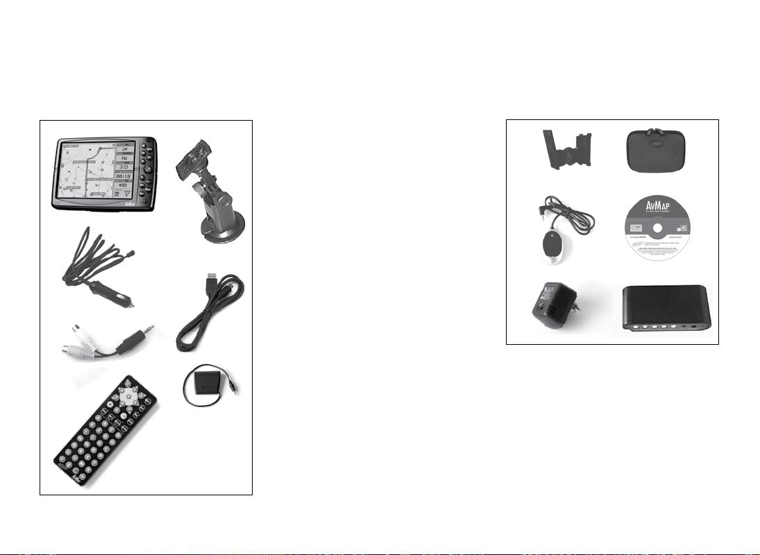
1.1 Box contents
1
3
4
5
6
2
Before using the product make sure the box
contains the following items:
1. Navigator (5,6” LCD TFT display)
2. Holder with suction cup
3. Car charger
4. USB cable
5. Audio video cable
6. Remote control
7. TMC receiver
8. This manual
1.2 Available accessories
7
1. Fixed holder
2. Carrying case
3. External GPS antenna
4. Maps updates on DVD
5. AC-DC Adaptor
6. TV Tuner
1
3
5
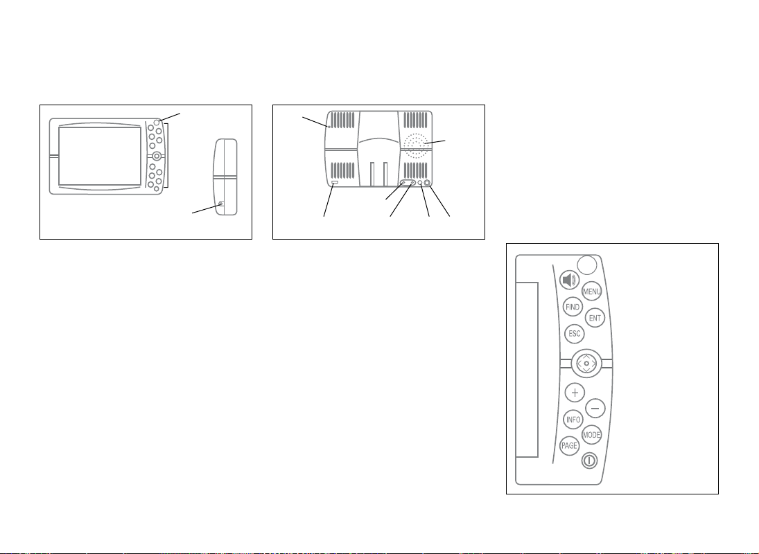
1.3 Hardware features
Looking at the navigator you can see the
following components:
1. Keyboard
2. 5,6” LCD TFT display
3. Infrared sensor
4. Audio output
N.B.: images are for illustrative purpose only
2
4
6
Page 9
3
2
1
5
10
trip computer pages
• PAGE: switches among the available pages:
map, instructions and the trip computer
• POWER: powers on and off the unit. Opens
the brightness control window.
front view
5. Brightness sensor
6. Power supply plug
7. Audio video input
8. Serial port for external GPS receiver
9. Serial port for TMC receiver
10. Speaker
11. USB port
1.4 Keyboard
• SPEAK: repeats the last vocal instruction
and opens the volume control window
• MENU: opens the main menus available
• FIND: opens find window to search for
addresses, marks, POI
4
side view
9
11
• ESC: exits from the current menu and
switches into cursor mode or GPS mode
• JOYSTICK:
Upper arrow: moves the cursor up
Lower arrow: moves the cursor down
Right arrow: moves the cursor right
Left arrow: moves the cursor left
• ENT: confirm a choice or selection, opens
the function menu
• + zooms in the map
• - zooms out the map
• INFO: opens the full info window
• MODE: switches among the different
viewing options for map, instruction and
8
67
9
Page 10

10
1.5 Remote control
1. Pull out the tab from the bottom end of
the remote control. The remote control is
ready to be used.
2. Point the remote control in direction of the
Geosat infrared sensor.
• MENU: opens the main available menus
• ENT: enter function to confirm a selection,
corresponds to the central part of the
joystick or to the + button in the navigator
keyboard
• ESC: exits from the current menu and
switches into cursor mode or GPS mode
• PAGE: selects the different pages available:
map, instructions and trip computer
• Upper arrow: moves the cursor up
• Lower arrow: moves the cursor down
• Right arrow: moves the cursor right
• Left arrow: moves the cursor left
• Upper-right arrow: moves the cursor
toward the upper right corner
• Upper-left arrow: moves the cursor toward
the upper left corner
• Lower-right arrow: moves the cursor
toward the lower right corner
• Lower-left arrow: moves the cursor toward
the lower left corner
• + zooms in the map
• - zooms out the map
• FIND: opens find window to search for
addresses, marks, POI
• INFO: displays the complete info on the
point on the map indicated by the pointer.
• MODE: allows entry to in advanced
functions available with further software
updates
• SPEAK: repeats the last vocal instruction.
• Alphanumeric keyboard: can be used to
edit names in the find window or to name
marks
Brightness adjustment with the remote
control
To adjust brightness with the remote
control:
1. Press the PAGE button for 3 seconds.
2. Adjust the display brightness with the right
arrow and left arrow of the JOYSTICK.
Press the ENT button to quickly change the
brightness level.
In this window it is also possible to choose
among the Auto brightness and Night Vision,
Page 11

2. Installation
in the second case the Auto night vision
option is also activated.
Volume adjustment with the remote control
To adjust volume with the remote control:
1. Press the FIND button for 3 seconds.
2. Adjust the volume with the right arrow and
left arrow of the JOYSTICK. Press the FIND
button to quickly change the brightness
level.
Geosat is ready to be used. All you need to do
is install the unit into the vehicle.
Carry out these operations in order:
1. Fix the bracket on the windscreen.
2. Fix Geosat on the bracket.
3. Plug the optional external antenna.
4. Plug in the car charger.
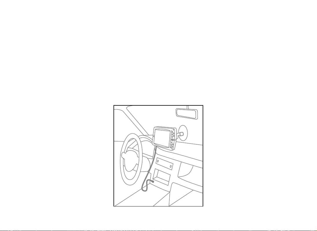
2.1 Fixing the bracket
Do not place the navigator on the passenger
seat, as this position could cause a dangerous
distraction for the driver.
The navigator should be fixed with the bracket provided.
The bracket with suction cup is included in
the box. There is also an optional fixed holder,
available upon request. In either case, please
follow the following instructions:
• Place the navigator in a position high
enough not to represent a risk of distraction
from driving
• Make sure that the bracket does not
represent a danger in case of accident or
sharp braking.
• Make sure that the bracket, the navigator
and the cables do not interfere with the
safety devices (e.g. airbag)
BRACKET WITH SUCTION CUP
The bracket should be fixed to the windscreen
via the suction cup. This will suit the majority
of vehicles. Before applying the suction cup,
carefully clean the glass.
1. Lightly moisten the suction cup and
place the flexible bracket in a position so
that the navigator will lie just above the
dashboard.
2. Fix the suction cup by pushing the locking
lever.
3. Fit the Geosat on the bracket.
FIXED-MOUNT BRACKET
An alternative fixed-mount bracket is available, that requires the dashboard to be
drilled.
1. Drill into a flat area of the dashboard.
2. Fix the base of the bracket with screws.
3. Fit Geosat on the bracket.
11
Page 12
12
2.2 Fitting the optional external
GPS antenna
The Geosat is equipped with a built-in GPS
antenna and with a port for an optional
external antenna. The external antenna can
be useful in case of shielded windscreens.
The external antenna does not need power.
The magnetic base of the external GPS
antenna can be placed on any flat metallic
surface, with the antenna facing up. The
higher the GPS antenna is placed, the better
it will receive the signal.
To guarantee a good signal place the external
antenna on the bonnet or on the roof. The
cable is made of a tear-proof material so
that it does not break if it is accidentally
closed between the door and the body of the
vehicle. The antenna should not be covered
with shielding materials (e.g. metal). Do not
put the antenna in the boot or in the glove
box.
2.3 Power connection
Whilst the Geosat is equipped with a built-in
Li-Io rechargeable battery, it is recommended
that you power the unit via the car cigarette
lighter / 12 V power socket during your
journey.
Geosat comes with the battery uncharged,
but the navigator can be used right away with
the car charger. The battery will require 4
hours charging to be fully charged.
Geosat can be fed with voltage between 10
and 35 V. The car charger cable provided in
the box should be used to power the Geosat
via the car cigarette/12 V power socket.
1. Plug the car charger cable into the Geosat.
2. Remove the cigarette lighter from its slot
or remove the 12 V power socket cover.
3. Insert the other end of the cable into the
socket.
Some vehicles are equipped with additional
12 V plugs.
The red LED on the plug confirms the correct
functioning of the power supply. If the LED is
off, check the connections or try again with
the vehicle engine on.
After positioning the antenna take its cable
inside the vehicle, passing it through the
passenger door seal and connect the end
plug into the Geosat.
The battery recharges when the navigator
is fed with the power supply cable, either
if it is on or if it has been switched off with
the PAGE button. In this case, the keyboard
Page 13
3. Set the destination
flashes until the Geosat is fully charged.
ATTENTION when the device encounters
internal temperatures of higher than 60°,
the battery will not recharge and an alarm
message will be displayed. This can happen
if the navigator is exposed for a long time
to direct sunlight in hot weather. In such
cases, it is suggested that you switch off the
navigator to recharge the battery.
Battery Functioning
Geosat battery allows the navigator to
operate even without feeding it with the
power supply cable.
When the navigator is used without power
supply, an icon (battery) indicating the level
of charging of the battery is shown. If this
icon is half green, the level of charge of the
battery is equal or less than half, if the icon is
fully green, it means that the level of charge
is more than half.
When Geosat for ALL is fed, another icon
(plug with batteries) is shown. There are two
status: if the icon is coloured in yellow, the
battery is recharing, if the icon is coloured
in green, it means that the battery is fully
charged.
The maximum autonomy of the battery in
optimal conditions ranges from 30 minutes
to 2 hours (according to the usage patterns).
It is possible to extend the autonomy of the
battery optimizing the energetic waste: in the
system setup it is possible to choose among
three levels of power save (no, medium,
maximum).
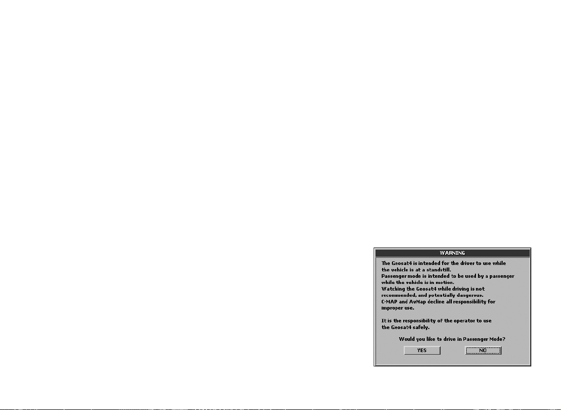
3.1 Starting
1. Switch on the navigator by pressing the
POWER button.
2. Geosat will display the software and
cartography display screen and then the
user is asked to choose the desired mode:
passenger or driver. An unaccompanied
driver should select the Driver mode.
3. Select one of the two buttons with the
JOYSTICK using the left or right arrow.
The selected button is outlined by a dotted
line.
4. Press ENT to confirm.
5. Wait for the satellite search to be completed
to see your position on the map.
13
Page 14
14
Driving mode
The driver should NOT consult the navigator
while driving.
For this reason, when Driver mode is chosen,
the map view is automatically deactivated.
The only accessible pages are the trip
computer and the list of driving instructions.
For further details, read par. 5.2.
Passenger mode
This mode allows access to all the navigation
functions.
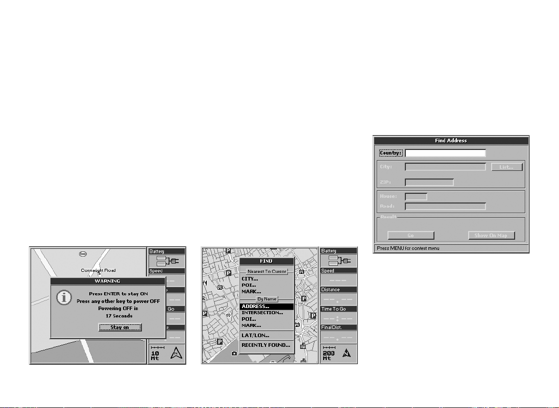
Powering down
To power down the Geosat press and hold
the POWER button for 4 seconds.
When the power supply cable is removed,
the message “powering off in 30 seconds”
appears. To avoid powering down, press
ENT. Press any other button to power down
immediately.
3.2 Setting the first destination
To plan a route, the easiest and fastest way is
take the current GPS position as the departure
point and insert the desired destination.
1. Press the FIND button. The Find menu will
now open.
2. In the Find menu select Address and press
the ENT button.
3. The Find address menu will now open.
The Country field is outlined with a dotted
line. Press the ENT button.
4. The virtual keyboard will now open.
Input the name of the country using the
JOYSTICK. For each letter selected, press
the ENT button. For ease of operation, the
auto-filling function is activated.
5. When the name of the Country is
completed, select ENT on the virtual
keyboard and confirm by pressing the ENT
button. This operation has to be carried out
the first time you search for an address. The
Page 15
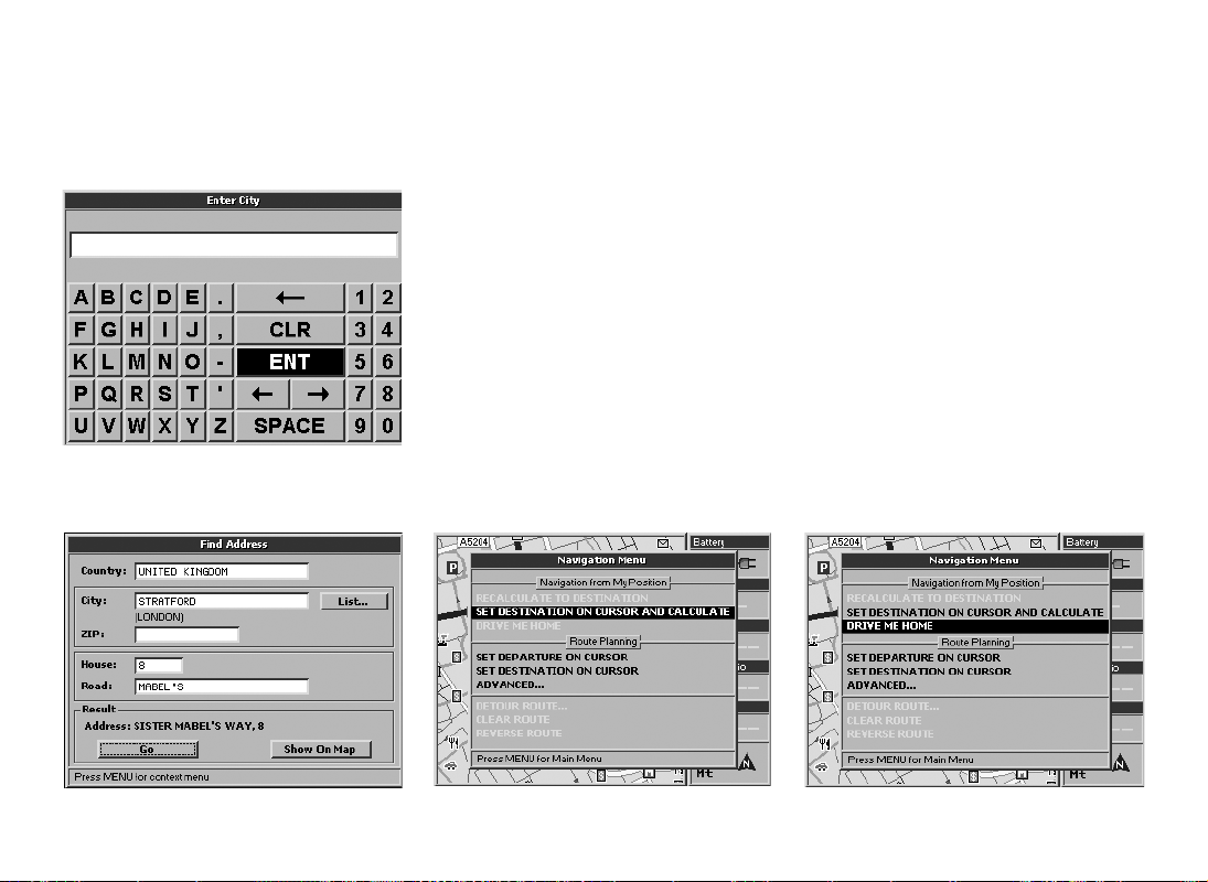
country is saved for subsequent searches.
6. Using the JOYSTICK, select the fields City,
Street and House Number (or Postcode
and House Number) and repeat the
procedure described for the Country field.
7. Once all the fields are filled, select Go
and press the ENT button. The Geosat will
calculate the route from the current GPS
position to the selected destination.
3.3 Show on map
The Show on Map button is useful for viewing
the inserted address on the map.
1. Select Show on Map and press the ENT
button.
2. Once the address has been checked, it
can be set as destination: ensure that the
cursor is on the required destination and
press MENU.
3. The Navigation menu will now open. From
Navigation from My position select Set
destination on cursor and calculate and
press the ENT button.
The Geosat will calculate the route from
the current GPS position to the selected
destination.
Alternatively, from the Find Address menu,
press the MENU button, select Show on map
and press the ENT button.
3.4 Drive Me Home
15
Page 16
16
4. Planning a route
After having set a Mark as Home (read par.
7.5) it is possible to set one’s own Home as
destination with a quick command:
1. Press the MENU button. The Navigation
menu will now open.
2. From Navigation from My Position select
Drive me Home and press the ENT button
to confirm.
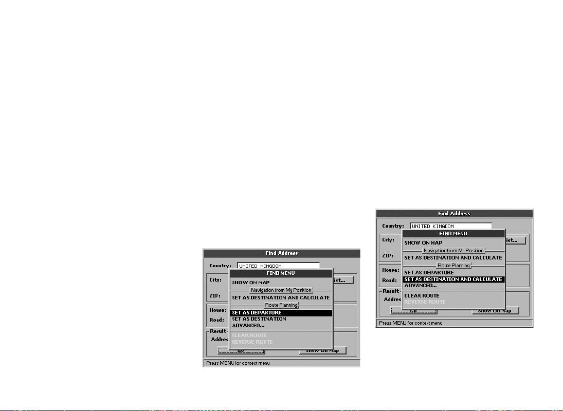
4.1 Planning a route from A to B
You can plan a route setting both the departure and the destination. This function can be
useful if you are in position X and you want
to plan a route from A to B, or if want to plan
a route before leaving, without receiving the
GPS signal.
How to set the departure:
1. Insert the desired address as described in
par. 3.2.
2. Once all the fields in the Find menu have
been filled, press the MENU button.
3. The Find menu will now open. From Route
planning select Set as departure and press
the ENT button.
How to set the destination:
1. Once the departure has been set, return
to the Find address menu. Insert the
destination address following the same
procedure as for the departure then press
MENU button.
2. The Find menu will now open. From Route
planning, select Set as destination and
calculate and press the ENT button.
4.2 Deleting a route
To delete the last route planned, follow these
Page 17

5. Advanced planning
instructions:
1. Press the MENU button. The Navigation
menu will now open.
2. Select Delete route.
3. Press the ENT button to confirm.
4.3 Reversing a route
To reverse the last route planned, follow
these instructions:
1. Press the MENU button. The Navigation
menu will now open.
2. Select Reverse route.
3. Press the ENT button to confirm.
4.4 Simulation
After having planned a route as described in
par. 3.4 it is possible to simulate the navigation.
1. Press the MENU button three times.
2. The System Setup menu will now open.
Move the JOYSTICK to the right to select
the Simulation folder and press the ENT
button to confirm.
3. Press the ENT button to start the
simulation.
4. Select Speed with the JOYSTICK and press
the ENT button to confirm.
5. Select the numbers with the right and left
arrow, and set the value with the up arrow
or down arrow.
For further details read par. 11.11.
5.1 Via points
If you want to set a sequence of destinations
or if the route viewed on the map does not
meet your needs, you can modify it, adding
up to 10 Via points. The Via point is represented on the map by a black and green flag
with a number from 1 to 10.
How to set a via point:
1. When the route has been set, press the
FIND button to open the Find menu.
2. Fill out the City and Road fields (or the
Postcode field) as described in the par.
3.2.
3. When all the fields have been filled, press
17
Page 18
18
the MENU button.
From Route planning, select Advanced
and press the ENT button.
4. The Advanced route-planning menu will
now open. From Via point select Set as via
point.
5. Press the ENT button to confirm. The
Geosat will calculate the new route.
You can set the Via point(s) first and then the
departure and destination points, or set the
departure point and then the Via point(s) followed by the destination. Via points must be
entered in the correct sequence.
How to remove a Via point:
1. Place the cursor on the first Via point
you want to remove then press the
MENU button. The Navigation menu will
now open. From Route planning, select
Advanced.
2. The Advanced route-planning menu will
open. From Via point select Remove next
Via point (to remove the next via point
with respect to the current GPS position)
Remove last Via point (to remove the
or
last via point that has been set).
3. Press the ENT button to confirm.
Example: to go from Fleet to London via
Woking, add Woking as a Via point and
the route will recalculated to go through
Woking.
Page 19

5.2 Blocking roads
When calculating a route, the Geosat allows
you to avoid some roads or parts of roads. A
road can be blocked even if there is no route
set.
How to block a road:
1. Place the cursor on the road to be
blocked.
2. Press the MENU button. The Navigation
menu will now open.
3. Select Advanced options and press the
ENT button to confirm.
4. The Advanced route-planning menu will
now open. From Blocked roads select
Set blocked road on cursor and press the
ENT button to confirm. The Geosat will
calculate the route. The blocked road will
be shown on the map with two red and
white icons linked by a red line.
the ENT button to confirm. If more than
one road has been blocked, you can select
Remove all blocked roads and press the
ENT button to confirm.
5.3 Reaching Walkways (Pedestrian
areas)
If the destination is a walkway, a window will
warn you that the street is not accessible. In
this case you can choose to activate the walkway or to go to the nearest accessible road.
1. Select, with the JOYSTICK, Enable
walkways or Use closest road.
2. Press the ENT button to confirm.
How to remove a block from a road:
1. Place the cursor on the blocked road.
2. Press the MENU button. The Navigation
menu will now open.
3. Select Advanced options and press the
ENT button to confirm.
4. The Advanced route-planning menu will
now open. From Blocked roads select
Remove blocked road on cursor and press
19
Page 20

20
It is also possible to activate/deactivate the
walkways following the procedure described
in par. 10.5.
5.4 Navigating Off road
With Geosat it is possible to plan a route off
road.
1. Press the MENU button three times.
2. The System Set up menu will now open.
Move the JOYSTICK to the right and select
the Routing folder and press the ENT
button to confirm.
3. Select Off Road from Route preferences.
4. It is now possible to select the departure
point off-road.
A-B Function
The A-B function is particularly useful during
off road navigation. This function allows you
to calculate the distance “as the crow flies”
between point A and B on the map:
1. Press the centre of the JOYSTICK. The
Function Menu will now open.
2. Select A-B Function and press the ENT
button to confirm. An “A” will appear in
place of the selected point on the Map.
3. Move the cursor to another point on the
map, repeat steps 1 and 2 to set the point
B.
4. A “B” will appear in place of the set point
on the Map and it will be linked to the “
point by means of a black line. A bar will
now open in the upper part of the display
showing the distance between A and B and
the angle from true north.
How to remove the A-B function:
1. Press the centre of the JOYSTICK. The
Function menu will now open.
2. Select Remove A-B and press the ENT
button to confirm.
5.5 Detour
Once the departure point and the destination
point have been selected, it is possible to
A”
Page 21

6. Using the map
view the list of all the streets along the route
and it is possible to detour the trip to avoid
an undesired street.
1. Press the MENU button to open the
Navigation menu.
2. Select Detour route to open the list of
the streets along the route and confirm by
pressing ENT
3. Select the list pressing ENT.
4. Select with the cursor the street to avoid
and press ENT to confirm.
5. Press ESC to exit from the list. Select
Detour and press ENT to confirm. The
route will be recalculated excluding the
streets to be avoided.
6.1 Exploring the Map
The position of the vehicle on the map is
represented by an Icon (e.g. a car).
Use the
the map. Press the
cursor mode in order to explore the map.
Press the
current GPS position.
In the system set up it is possible to customize
the level of detail of the Map, that is to say
the quantity of information displayed.
1. Press the MENU button three times to
2. Move the JOYSTICK rightwards to select
3. Select the submenu Map Detail and press
4. Select with the JOYSTICK simple, normal
In the same window, in the
submenu it is possible to customize the icon
representing the vehicle: standard or car, and
the display of the User Mark info: Off, icon,
icon/label.
For more details read par. 11.3.
+ and – buttons to zoom in or out
ESC button again to go back to your
open the System Setup menu.
the
Map folder.
ENT to confirm.
or full.
ESC button to enter the
Fix Symbol
6.2 Alternative Views
Once a route is set, you can choose to display
the trip information in different pages by
pressing the PAGE button: map, maneuvers,
trip computer and video input (displayed
only if an external device is connected to the
audio-video input); while pressing the MODE
button you can choose different view modes
for each Page.
Starting from the Map with info box on the
right side by pressing the
can obtain the following configurations:
• Map with Next maneuver (upper bar). The
instructions include direction, distance or
MODE button you
21
Page 22

22
time to the next maneuver.
• Full display map
Pressing the PAGE button you can pass
the maneuver pages, then pressing the
MODE button you can obtain the following
configurations:
• Full display instruction
• List of instructions
• Back to Map with info box on the right
Pressing the
the trip computer pages, then pressing the
MODE button you can obtain the following
configurations:
PAGE button you can pass
Page 23

• Trip Computer Pressing again the PAGE button, the unit
• Graphic of speed
will display pictures or films coming from
the Video PAL, NTSC input (only when an
external device is connected to the audio
video input).
6.3 Driver mode
When the Driver mode is chosen, these
pages are available:
• Trip computer
• List of instructions
• Full display instructions
6.4 2D and 3D views
With the Geosat you can view the map in 2D
or 3D.
2D: the map is bi-dimensional; this view
allows clear reading of all the names of the
surrounding roads.
3D: the map has a perspective view for a
more lifelike navigation. This view can only
be used for navigation with a GPS signal,
while consultation of the map and simulation
take place in 2D.
When in 3D view, if you press ESC to move to
cursor mode, the view automatically changes
to 2D; press ESC to return to 3D view.
To set the map view read par. 11.3.
6.5 Night vision
With Geosat it is possible to set the night
vision for a safer consultation and driving at
night. With the night vision, the colour palette
is changed so that menu and cartography are
readable but not disturbing in absence of
light. To switch to the auto night vision:
1. Press and hold for 1 second the POWER
button to open the Brightness Menu.
2. Select with the cursor Night vision and
confirm by pressing the + button.
It is also possible to set the auto night vision
23
Page 24

24
7. Managing Marks
in the same menu or from the system setup.
For further details read par. 11.14.
6.6 Points of Interest (POI)
The database of the points of interests is very
useful when you are in an unfamiliar place.
This information is preloaded in the Geosat,
together with the cartographic data. The POIs
include hotels, restaurants, hospitals, police
stations, cinemas etc and are grouped in
these categories:
• Car services
• Transports
• Emergency
• Attractions
• Entertainment
• Food and drink
• Government
• Lodging
• Medical services
• Natural attractions
• Services
• Shopping
• Sport facilities
• Other
To select which POI categories to view, read
par. 11.4.
The Geosat holds more than 300,000 Points
of Interest in the UK (more than 1,800,000
in Europe).
To search a POI by name, either near to the
cursor or to the GPS position, read par. 8.6.
Safety Cameras
This is a special category of POI, for fixed
and mobile safety cameras. This database
can also be updated from an external file and
can be alerted with an alarm. To set the alarm
read par. 11.7.
For more information about the Safety
Camera database read par. 10.3.
7.1 Creating Marks
Geosat allows you to create and save user
points called Marks for example, the address
of a restaurant, of your home, of a client etc.
How to add a Mark on your GPS position:
Press the centre of the JOYSTICK to open the
Function menu, select Add Mark on cursor
and confirm by pressing the ENT button.
How to add a Mark on a specific address:
1. Insert the desired address following the
procedure described in par. 3.2 and 3.3.
2. Select Show on map and press the ENT
button to confirm. The cursor will indicate
Page 25

the desired address.
3. Press the centre of the JOYSTICK. The
Function menu will now open. Select Add
Mark on cursor and press the ENT button
to confirm.
7.2 Mark folders
To browse the Marks folders press the MENU
button twice, select Marks list and press the
ENT button to confirm. The Mark folder list
shows the Business, Personal, Incoming and
Trip 1 folders. When a new Mark is created
on the map, it is automatically saved in the
Personal folder.
It can subsequently be moved to other
folders.
Press the MENU button to open the Folder
options menu from which you can add,
modify or delete a folder.
How to create a new folder:
1. Press the MENU button to open the Folder
options menu, select Add Folder and press
the ENT button to confirm.
2. In the Add folder window, the Name field
When the name is complete select ENT
on the virtual keyboard and confirm by
pressing the ENT button, then select OK
and again confirm by pressing the ENT
button.
The Folder options menu also includes a
Communication submenu:
• Send Marks
• Receive Marks
• Send tracks
These advanced functions can be used with
the optional PCPlanner software. See par.
6.7.
7.3 Mark list
To view the list of the Mark points:
1. Press the MENU button twice, select Marks
List and press the ENT button to confirm.
2. In the Mark folder list select the desired
folder and press the ENT button.
is outlined with a dotted line.
3. Press the ENT button to open the virtual
keyboard. Write the name of the folder
selecting letter by letter with the JOYSTICK.
Press the MENU button to open the Mark list
menu from which you can Show on map, Set
a Mark as destination or use two or more
marks to set a route.
25
Page 26

26
Press the
options menu. From this menu, it is possible
to Edit a Mark, Remove a Mark, Remove all
marks or Search a Mark by name in the list
of created points.
The Marks options menu includes also a
Communication submenu:
• Send Marks
• Receive Marks
7.4 Editing a Mark
Once a Mark has been created you can modify
the icon, the name and the description.
1. Point the cursor on the Mark and press
ENT button to open the Marks
the centre of the JOYSTICK. The Function
menu will now open.
2. Select Edit Mark on cursor and press the
ENT button to confirm. The Edit Mark
menu will open.
Or from the Marks list:
1. Press the MENU button twice, from Main
menu select Marks list and press the ENT
button to confirm. The Marks list folder
menu will now open.
2. Select the Mark to be edited and press the
ENT button to confirm.
3. The Mark Options menu will open. Select
Edit Mark and press the ENT button to
confirm.
In both cases the Edit Mark window will
open.
3. The Name field is outlined with a dotted
line. Press the ENT button to open the
virtual keyboard. Write the name of the
folder selecting letter by letter with the
JOYSTICK. When the name is complete
select ENT on the virtual keyboard and
confirm by pressing the ENT button, then
select OK and again confirm by pressing
the ENT button.
4. Select Description and repeat the same
procedure described as for the Name
Page 27

field.
5. To choose an icon select the field Icon with
the JOYSTICK and press the ENT button to
confirm. Select the desired icon and press
the
ENT button again.
6. To save everything select OK and press the
ENT button to confirm.
How to show a Mark:
It is possible to cusromize the information
associated to a Mark.
1. Press three times the MENU button to
open the System Setup menu.
2. Move the cursor rightwards to select the
Map folder. Select the User Marks submenu
and press the
3. Choose among three options: OFF (no
mark is displayed), Icon (the marks are
displayed with an icon), Icon/label (the
marks are displayed with an icon and
name).
4. Confirm the chosen option by pressing
the ENT button, press ESC to exit from the
System set up Menu.
How to remove a Mark:
1. Select the Mark you want to remove with
the cursor or from marks list as described
above.
2. Press the centre of the JOYSTICK. The
Function menu will now open.
3. Select Remove Mark and press the ENT
button to confirm. A warning window will
now open. If you are sure you wish to
remove the Mark select OK and confirm
by pressing the ENT button.
How to move a Mark:
A Mark can be moved to another position:
1. Place the cursor on the Mark you want
to move and press the centre of the
JOYSTICK. The Function menu will now
ENT button to confirm.
open.
2. Select Move Mark on cursor and press the
ENT button to confirm.
3. Move the cursor to the new position and
press the ENT button to confirm.
7.5 Setting a Mark as HOME
A frequently used Mark (for example your
home) can be set as HOME, so that it can be
quickly set as destination from the Navigation
menu without having to select the mark with
the cursor or from the Marks list.
How to set a Mark as HOME:
1. Select the desired Mark as described in
27
Page 28

28
par. 7.4.
2. Select Set as HOME and press the ENT
button to confirm. The Mark icon will be
changed into the HOME icon.
You can then set home as your destination
with this quick command:
1. Press the MENU button. The Navigation
menu will open.
2. From Navigation from my GPS position
select Drive me HOME and press the ENT
button to confirm.
7.6 Mark alarm
Geosat can alert you with a visible message
and a beep when you are in proximity of one
or more Marks associated with the danger
icon.
to activate the alarm.
For further details read par. 11.7
Only Marks associated to the danger icon
can be alerted.
7.7 Sending and receiving Marks
There is an accessory software called
PCPlanner that makes it possible to transfer
marks and data from a PC to Geosat and vice
versa.
The transfer is made through serial
connection and not directly on the secure
digital memory.
To activate this function observe the following
instructions:
1. Press the MENU button, select System
Setup and press the ENT button to
confirm.
2. Move the JOYSTICK to the right to select
the Alarm folder and press the ENT button
to confirm.
3. Select Mark alarm and press the ENT
button to confirm. In the Alarm radius
field, you can set the radius within which
7.8 File manager
Updating the map data may cause the loss of
your user Marks. To avoid this inconvenience
it is recommended that you save the Marks
and tracks that you have created.
How to save user files:
1. Press the MENU button twice, select File
manager and press the ENT button to
confirm.
The memory is initialised automatically and
Page 29

prepared for saving the data. The space
already used on the Hard Disc is shown in
the lower part of the display.
2. Press the MENU button. The File menu
will open.
3. Select Save and press the ENT button to
confirm.
4. The Save to disc window will open. The
Name field is outlined with a dotted line,
Press the ENT button to open the virtual
keyboard.
5. Insert the name for the file using the
JOYSTICK to select the letters. After each
letter, press the ENT button. When the
name is completed select ENT on the
virtual keyboard and confirm by pressing
the ENT button.
6. Move the JOYSTICK to select Type, press
the ENT button and select the type of data
to be saved – i.e. Marks or Tracks. Press
the ENT button to confirm.
7. Move the JOYSTICK to select OK and press
the ENT button to confirm.
8. A warning message will be displayed. Press
the ENT button to save the Marks.
It is possible to save up to 1000 Marks.
After a RAM clear or a software update you
can reload previously saved Marks:
1. Press the MENU button twice, select File
manager and press the ENT button to
confirm.
2. Select the saved file that contains the Mark
to be reloaded. Press the MENU button.
The File menu will open.
3. Select Load and press the ENT button. A
warning message will open. To load the
Marks select OK and press the ENT button
to confirm.
How to delete the user data:
To permanently delete a file containing user
data (your Marks/Tracks):
1. Press the MENU button twice, select File
manager and press the ENT button to
confirm.
2. Select the file to be deleted. Press the
MENU button. The File menu will open.
3. Select Delete and press the ENT button.
A warning message will be displayed. To
delete the Marks/Tracks select OK and
press the ENT button to confirm.
It is not possible to overwrite the content of
an existing file. The refresh option is used
to read the content of the Hard Disc again
when the saved marks folder(s) have been
updated.
29
Page 30

30
8. Advanced search options
8.1 Duplicate place/road names
When inserting an address you will inevitably
find roads or towns with the same name. The
Geosat will display a list of all roads or towns
with the same name. Select the required
road/town and confirm by pressing the ENT
button.
8.2 Searching by postcodes
The postcodes field allows you to search for
an address by postcode. The postcode field
is not mandatory, but can be used instead of
the city field. Move the JOYSTICK to select
Postcode and press the ENT button to open
the virtual keyboard. Select the letters with
the JOYSTICK.
To make this operation easier the auto-filling
function is activated.
8.3 Searching for intersections
If you do not know an exact address or
postcode, you can search for the intersection
between two streets. This can be a very useful
function when navigating in big cities.
1. Press the FIND button. The Find menu will
open.
2. From By name select Intersection and
press the ENT button.
3. The Find intersection menu will open. Fill
the fields State and City or Postcode.
4. Select Road1 with the cursor and press the
ENT button to open the virtual keyboard.
When you have added the road/street
name, select
and confirm by pressing the ENT button.
5. Repeat the operation for Road2.
6. Select Go and press the ENT button. The
Geosat will calculate the route from the
current GPS position toward the found
intersection.
7. Alternatively, select Show on Map and press
the ENT button. Once the intersection has
been found it can be set as destination.
Press the MENU button. The Navigation
menu will open.
From Navigation from my GPS position
select Set as destination and calculate and
press the ENT button to confirm.
8.4 Searching near to the cursor or
to the GPS position
The Geosat allows you to search for towns/
cities, Points of Interest and Marks within in
a radius of 50 km from:
ENT on the virtual keyboard
Page 31

• The current GPS position
• The position of the cursor on the map
If you can see both the GPS position and
the cursor on the map, the search will be
performed near the cursor.
To search near the current GPS position, you
must exit from the cursor mode by pressing
the ESC button. The cursor will be removed
from the display.
The Find menu will show the search criteria
in use.
8.5 Searching for the nearest cities
1. Press the FIND button. The Find menu will
open.
2. From Nearest to cursor select City and
press the ENT to confirm. A list of the cities
near to the cursor or to the current GPS
position will open. Choose the desired
city.
To set it as destination:
1. Press the MENU button. The Find menu
will open.
2. From Navigation from my GPS position
select Set as destination and calculate and
press the ENT button to confirm.
Alternatively, select Use in Find address to
open the Find address page filled with the
chosen cities. At this point, the remaining
fields can be completed.
8.6 Searching nearest POI
In the same way as you can search for the
nearest cities, you can also search for the
nearest POI (for POI read par. 5.4).
1. Press the FIND button. The Find menu will
open.
2. From Nearest to cursor select POI and
press the ENT button to confirm.
3. The POI categories will open.
4. Select a category with the cursor and
press the ENT button to view the POI
subcategories menu.
31
Page 32

32
5. Select the desired subcategory and press
the ENT button to confirm.
6. The Search window of the chosen category
will open. This window displays a list of
the points of interest near to the cursor
or to the current GPS position. Select the
required POI.
To set the chosen POI as destination:
1. Press the MENU button. The Find menu
will open.
2. From Navigation from my GPS position
select Set as destination and calculate and
press the ENT button to confirm.
In the Find menu select POI Info to view the
detailed info for the Point of Interest, which
gives address and telephone number details.
8.7 Searching POI by name
It is possible to search the Points of Interest
database for (e.g) a restaurant, a hospital or a
hotel by name.
1. Press the FIND button. The Find menu will
open.
2. From By Name select POI and press the
ENT button.
3. The POI category window will open.
4. Select a category with the cursor and press
the ENT button.
5. The POI subcategories will open. Select
the desired subcategory and press ENT to
confirm.
Page 33

6. The Find menu for the chosen subcategory
will open. Open the virtual keyboard by
pressing the ENT button and insert the
name of the town/city in which the POI
falls.
7. Select Name with the cursor. When you
have entered the name, select ENT on the
virtual keyboard and confirm by pressing
the ENT button. The Geosat will search for
the POI in the named town/city.
Once the Point of interest has been chosen,
it can be set as destination as described in
par. 8.6.
8.8 Searching nearest Marks
In the same way as you can search for the
nearest cities or POI, you can also search for
the nearest Marks (for Marks read par. 6.1):
1. Press the FIND button. The Find menu will
open.
2. From Nearest to cursor select Mark and
press the ENT button to confirm.
3. The Nearest Marks window will open
displaying the list of Marks near to the
cursor or to the current GPS position.
Once the desired Mark has been chosen it
can be set as destination.
1. Press once the MENU button.
2. The Find menu will open. From Navigation
from my GPS position select Set as
destination and calculate and press the
ENT button to confirm.
8.9 Searching Marks by name
It is possible to search a Mark by name from
Marks that you have created and named.
1. Press the FIND button. The Find menu will
open.
2. From By Name select Mark and press the
ENT to confirm.
3. The Mark by name menu will open. The
Mark name is outlined with a dotted line.
Press the ENT button to open the virtual
keyboard and ty the name of the mark you
want to search for.
4. When this field is completed, select ENT
on the virtual keyboard and confirm by
pressing ENT.
Once the Mark has been chosen it can be set
as destination.
5. Press the MENU button. The Find menu
will open.
6. From Navigation from my GPS position
select Set as destination and calculate and
press the ENT button to confirm.
33
Page 34

34
8.10 Recently found
In Recently found, you can find the list of the
last found addresses, Marks and POI.
1. Press the FIND button. The Find menu will
open.
2. Select Recently found and press the ENT
button to confirm.
3. To quickly set a route to a recent
destination, select it with the cursor and
press the MENU button. The Find menu
will open.
4. From Navigation from my GPS position
select Set as destination and calculate and
press the ENT button to confirm.
Find menu select Clear List, to delete
In the
all the data included in recently found.
8.11 Searching by Latitude and
Longitude
It is possible to search a point by its LAT/LON
coordinates:
1. Press the FIND button. The Find menu will
open.
2. Select LAT/LON and confirm by pressing
the ENT button.
3. To insert the coordinates move the cursor
upwards or downwards.
4. Press the MENU button. The Find menu
will open. From Navigation from my GPS
position select Set as destination and
calculate and press the ENT button to
confirm.
In the Find menu it is also possible to select
Save as Mark, to save the found point as a
Mark.
Page 35

9. Trip information
9.1 Trip computer
To view the trip computer page, press the
PAGE button. The trip computer includes
the following information (calculated by the
Geosat):
• Speed
• Trip Distance
• Total Distance
• Average speed
• Overall Average speed
• Maximum speed
• Driving time
• Trip time
• Stopped Time
Press the MENU button on this page to open
the Trip menu to reset the trip data saved up
to that moment (excludes the total distance).
The Total distance can only be reset with a
ram clear (memory reset). For further details
read par. 6.8.
9.2 Data boxes
You can customize the information included
in the column on the right-hand side of the
display.
1. Ensure that the right-hand column is
displayed on the screen. If it is not, press
PAGE until it is displayed.
2. Press the MENU button twice. Select Setup
data boxes and press the ENT button to
confirm.
3. Select, from the right-hand column, the
data box to be modified and press the ENT
button.
4. In the left-hand window, select the new
item to be displayed in the chosen the box
and press the ENT button.
Any of the six data boxes can display one of
the following:
Trip: Maximum speed
Maximum speed reached
Trip: Driving time
Trip: Stopped time
Trip: Total time
Driving time + stopped time
Trip: Trip distance
Trip: Total distance
Trip: Overall average speed
Trip: Driving average speed
Time: Time
Time: Date
35
Page 36

36
Time: Count down timer
Time: Elapsed timer
Navig: Current speed
Navig: GPS status
Navig: Altitude
Navig: Fix Lat/Lon
Coordinates of current position
Navig: Cursor Lat/Lon
Coordinates of the cursor
Navig: Course
The direction of the route
Navig: Distance to turn
Distance to the next turn
Navig: Bearing to turn
The direction of the turn vs. the
geographic North
Navig: Estimated time to turn
The time at which the next turn is
estimated to take place
Navig: Time to go
Navig: Final distance
Km left to destination
Navig: Final time to go
Navig: Maidenhead grid
Info: Scale and north indicator
Info: Fix and cursor Lat/Lon
Info: Sunrise/sunset
Info: Battery status
9.3 GPS Information
To get information on the Global Positioning
System, follow these instructions:
1. Press the MENU button twice. The Main
Menu will open.
2. Select GPS Page and confirm by pressing
the ENT button.
3. The GPS page will open with information
on position and on the strength of the
signal received from satellites.
This information is displayed:
• GPS status
• Date & Time
• Latitude/Longitude
• Speed
• Course (relative to true North)
• Altitude
• HDOP (Horizontal Dilution Of Position)
- the lower the value, the higher the
precision
From the GPS page, press the
to open the GPS Menu page, from which you
can reinitialise the satellite receiver or restart
the GPS.
MENU button
Page 37

10. Special functions
10.1 Video function
The audio/video input (PAL NTSC) allows you
to connect DVD players, laptops, cameras
etc., to the Geosat display.
1. Turn on the device and connect the audio
video cable to the plug on the back of the
navigator.
2. Connect the RCA video cable to the yellow
pin, and one of the two audio cables to the
white pin (mono).
3. Press the PAGE button until the video
mode is displayed.
10.2 TMC
Geosat software is ready to process traffic
information in real-time. Geosat is equipped
with a plug for a TMC (Traffic Message
Channel) external receiver which can be
purchased as an accessory. The TMC receiver
allows to receive traffic information through
the RDS radio channel.
1. Connect the TMC receiver plug in the right
serial port.
2. Press three times the MENU button to
open the System Setup menu.
3. Move the cursor rightwards to select the
Interface folder and confirm by pressing
the ENT button.
4. In the Interface submenu select with the
TMC and press ENT to activate it.
How to set the TMC alarm
1. Press three times the MENU button to
open the System Setup menu.
2. Move the cursor rightwards to select the
TMC folder and confirm by pressing the
ENT button.
3. Select the Traffic alarm checkbox and
press ENT to activate it.
4. Select, with the cursor, Alarm Range and
press ENT to set the value of the distance
within which all the traffic events are
detected.
5. Set the value using the up and down
arrow.
Now the TMC is fully functioning. Once the
receiver is connected, the traffic events will
be displayed in different ways:
a. The streets will be coloured according to
their traffic status
b. Traffic info will be displayed in the selected
text language in warning windows
c. Special icons on the map will indicate the
traffic events such as accidents or bad
37
Page 38

38
weather conditions
d. In the time to go, the software will compute
the delay due to traffic event
The software will allow the driver to choose
whether to modify the route to avoid the
traffic event.
To view the status of the TMC receiver
1. Press the MENU button twice.
2. Select Traffic info and confirm by pressing
the ENT button.
The Traffic info window will open and display
all the data related to the TMC receiver.
10.3 Safety Camera database
In some countries safety cameras POI
databases are publicly available from several
sources such as web sites. It is possible to
import these databases in .ov2 format into
Geosat navigators.
To load the safety cameras POIs on the map:
1. Visit the www.avmap.it web site and click
on support.
2. Click on FAQ’s and Downloads.
3. Select the model of navigator from the
drop down menu.
4. Click on software update: the latest version
will be displayed.
5. Click on download.
6. Insert Login and Password received with
the product registration.
If the software has never been updated it
is necessary to register the product and
download the drivers (read par 12.1).
Once the GSUPDATE application is
downloaded and launched, it can be used
to update the software or just to transfer the
POI database from the Pc to the navigator.
1. Click on the Transfer database button.
2. Browse the PC to select the downloaded
database.
3. Associate the database to a safety camera
category and icon (fixed speed cameras,
mobile, traffic lights, special).
The files will be loaded on the navigator and
converted into the AvMap format.
10.4 APRS
APRS is a system developed by Bob Bruninga,
WB4APR, which uses amateur radio to
transmit position reports, weather reports,
and messages between amateur radio users.
APRS stands for Automatic Position reporting
System. It is the integration of Hardware
(Amateur radio equipment and GPS) with
software to provide real – time disseminating
of data concerning real-time events and
to graphically represent that data on their
computer, or GPS display.
AvMap Geosat 4 navigators are APRS
compatible and are capable to communicate
with radio VHF devices such as Kenwood
D700A e TH-D7AG. The radio equipment
has to be connected to the TMC serial port.
To configure the communication protocol of
the serial port:
1. Press three times the MENU button to
open the System Setup menu.
2. Move the JOYSTICK rightward to select
the Interface folder.
3. Select with the JOYSTICK Radio link and
confirm by pressing ENT.
4. Press ESC to exit from the System Setup
menu.
Transmit and receive positions via APRS
The communication is bi-directional: it allows
transmitting your GPS position via radio and
to view the positions of the other users on
the display of your navigator.
The positions of the other users are received as
Mark points, still or in motion. The positions
Page 39

11. Setting preferences
are displayed on the map and it is possible to
view the full list of received marks:
1. Press twice the MENU button to open the
Main Menu.
2. Select with the cursor Mark List and
confirm by pressing ENT to access to the
list of Mark folders.
3. Select the Incoming folder and confirm by
pressing ENT o view the list of the Marks
received via radio.
Set an APRS Mark as destination
It is possible to set as destination, both still
marks and Mark in motion thanks to the
special function ‘intercept to target’:
1. Select the desired Mark in the Mark List.
2. Press MENU to access to the Mark List
Menu.
3. Select Set as destination and confirm by
pressing ENT.
The selected mark will be set as destination
even if it is moving: the software will update
constantly its position and follow it.
10.5 Connection to GSM localization
devices
All the functions available with the Radio
link are also available for GSM localisation
devices.
11.1 System setup
On the Geosat you can set a variety of
preferences, allowing you to customize your
Geosat according to your needs.
To access to the system set up press the
MENU button twice, select System setup and
press the ENT button to confirm. The System
setup window has the following folders:
• General
• Map
• POI
• Routing
• Track
• Alarms
• Date & Time
• Units
• Text language
• Voice language
• Simulator
• Interface
• TMC
Move the JOYSTICK to select the desired
folder and press ENT to confirm.
Select the parameter to be modified and
press the ENT button to confirm.
39
Page 40

40
To exit from a menu press the ESC button.
If, after modification, you wish to return to
the former settings, you can restore the
default settings:
1. Press the MENU button twice, select
System setup and press the ENT button to
confirm.
2. In the General folder, select Factory
defaults.
11.2 General
Regional settings
It sets the continent in which the Geosat will
be used. The choices are:
• Europe
• USA
To use a Geosat that was purchased in
Europe in the USA, you need to add a licence
to allow the device to read US maps. For
further information on how to obtain both
the licence and the US maps, email info@
avmap.it.
Beeper
It activates/deactivates the button sounds.
Power save
It sets the level of power save after that the
power supply cable has been removed.
• OFF: no variation is applied when the
power supply cable is removed
• Medium: the brigthness is automatically
reduced after that the power cable is
removed
• Maximum: the display goes in stand by
after 30 seconds of inactivity after that the
power supply cable is removed
Factory defaults
It restores the original default settings.
Color Theme
It changes the colour used as background for
the menus.
• Blue
• Grey
• White
Voice instructions
It sets the frequency and type of voice
prompts.
• Simplified: the navigator provides the
main instructions for manoeuvres.
• Detailed: provides further info on the
GPS status and on the instructions to be
followed.
Night Vision
It changes the colours palette used in the
display for enhanced night vision.
Auto brightness
It activates/deactivates the automatic
regulation of the display brightness.
11.3 Map
Map details
It sets the amount of detail displayed on the
map:
• Simple
• Normal
Page 41

• Full
Auto position
It is possible to choose whether the zoom
level has to vary automatically during
navigation, according to speed and distance
to the next turn or whether to keep your own
GPS position centred on the map:
• Manual: once the zoom level has been set
manually, this remains constant for all the
navigation.
• Auto zoom: the zoom level is varied
automatically according to speed and
distance to next turn.
• Auto centre: the zoom level is varied
according speed.
Auto info
It activates or deactivates the automatic info
that is displayed when the cursor is placed on
any point of the map. The info box shows the
name of the street and of the objects found
near the cursor.
Traffic overlay
It activates/deactivates the windows showing
the traffic information from the TMC receiver.
The software processes, in real time, the
traffic data and displays the information in
the pre-set language. (External TMC receiver
needed)
Map mode
It sets the criteria for the map view.
• North up: the 2D map stays fixed with the
• Direction up: the 2D map rotates so that
• 3D View: for navigation with a GPS signal,
Scale format
Type of scale:
• Bar: a segment proportional to the
north up.
the vehicle direction is always facing up.
the map can display a 3D view (with
direction up).
indicated distance.
• Level: indicates the zoom level.
• Width: indicates the distance covered by
the display.
Fix symbol
You can choose which icon represents your
GPS position:
• Standard
• Car
User Marks
It sets the way Marks are displayed:
OFF: no Marks are displayed
Icon: Marks are displayed with icons
Icon/Label: Marks are displayed with icon
and name
11.4 POI
On this page, you can choose which POI
categories are displayed on the map.
To include or remove a category, select it
with the JOYSTICK and press the ENT button
to confirm.
The POIs associated to a category are
displayed when the category checkbox is
selected.
The safety cameras checkbox is activated
41
Page 42

42
when safety cameras POIs are uploaded on
the navigator (read par 10.3).
Only for Geosat 4 CAMP version are
available for France, Italy, Germany and UK
about 20,000 Points of Interest dedicated
to Recreational Vehicles (Campers and
Caravans): RV campgrounds, RV parking,
camping and RV services.
11.5 Routing
Route preference
It specifies the criteria used to calculate the
route:
• Fastest: roads with higher speed limits
preferred.
• Shortest: the shortest distance is
preferred.
• Fewer turns: the route with the fewer turns
is preferred.
• Off road: off road, “as the crow flies”
navigation is activated.
• Best for truck (only for Geosat 4 TRUCK):
calculates the best for Trucks avoiding
streets that are not practicable according
to Tele Atlas data.
Route draw mode
Selects the mode in which the route is
displayed:
• Background: the route is highlighted in
yellow on the background so that the
cartographic details along the route are
visible.
• Foreground: the route is highlighted in
green covering the cartographic details
under it.
Avoid
In calculating the route, you can choose to
avoid:
• Toll roads
• U Turns
• Highways
• Walkways (Pedestrian areas)
• Ferry routes
• Built-up areas
• Unpaved roads
Turn details
With this option checked, the screen freezes
to show the detail of the forthcoming
manoeuvre. The turn details are set as off
default.
11.6 Track
On this page, you can customize the manner
in which the Geosat displays and records the
Page 43

detailed tracks select a higher value
• Auto
• 1 sec
• 5 sec
• 30 sec
• 20 m
• 100 m
• 500 m
track.
Track display
Check this box to view the track of the route
that has been followed.
Track recording
Check this box to record the track of the
route that has been followed.
Track recording step
This sets the time interval or distance between
successive points stored in the track. For
more detailed, shorter tracks, select a lower
value of time or distance or for longer, less
Clear Track
Permanently clears the saved track
Remaining Track
It shows the remaining space available in the
memory for Track(s) recording.
Track colour
Allows selection of the track colour. This
option is available when the Track display
option is checked.
11.7 Alarms
GPS fix lost alarm
Select this option to activate an alarm to alert
you to loss of the GPS position.
Speed alarm
Select this option to activate the alarm when
you have exceeded a set speed limit.
The speed limit field determines the limit
above which the alarm is activated.
Mark alarm
Select this option to activate the alarm for
the proximity of a Mark point associated to
a danger icon.
The Mark alarm radius determines the
distance at which the alarm is activated.
Safety Camera alarm
Select this option to activate the alarm for
the proximity of a safety camera. (For further
information read par. 10.3).
43
Page 44

44
The Alarm radius determines the distance at
which the alarm is activated.
To modify the radius, select the field to be
modified and move the JOYSTICK either up
or down, then confirm by pressing the ENT
button.
11.8 Date & Time
Time format: 24h or 12h.
Date format: Month/Day/Year or Day/Month/
Year.
UTC offset: sets the difference between the
local time and Greenwich Mean Time.
Countdown timer: set the duration of the
countdown (h/min/sec) and press start.
Elapsed timer: press start to start the timer.
11.9 Units
Distance
Sets the unit for distance:
• Nm: nautical mile (1 nm = 1.85 km)
• Sm: Statute mile (1 sm = 1.6 km)
• Km: Kilometre
Depth
Sets the unit for depth:
• Ft: feet (1 ft = 0.3 m)
• FM: fathom (1 fm = 6 ft)
• Mt: meter
Altitude
Sets the unit for altitude:
• Ft: feet (1 ft = 0.3 m)
• FL: flat level (1 fl = 100 ft)
• Mt: meter
Speed
Sets the unit for speed:
• Kts: knot (1 kts = 1.85 km/h)
• Mph: miles per hour (1 mph = 1.6 km/h)
• Km/h: kilometres per hour
North reference
Sets which North is used as reference in the
navigation:
• TRUE: geographic (true) North
• MAGNETIC: magnetic North
Direction
Indicates the units used for direction:
• Cardinal letters: value referred to as
cardinal points of the compass (N,S,W,E)
• Numeric degrees: value referred to as
degrees of the compass.
11.10 Text language and Voice
Language
These folders list the available languages for
Page 45

the Geosat software and voice prompts:
• English
• Italian
• French
• German
• Spanish
• Danish
• Dutch
• Czech
• Polish
• Slovenian
• Slovakian
• Català (only voice)
• Greek (only voice)
Not all the languages that are available for text
messages are available for voice prompts.
To have all the available languages it is
suggested that you update the software
periodically. You can always obtain the latest
software version, free of charge by visiting
www.avmap.it.
11.11 Simulator
You can plan a route and view a simulation
of the navigation without connecting the GPS
antenna. In the simulation window check the
simulation option, and Geosat will display
the vehicle icon moving on the route as if you
were navigating for real.
Simulation
Sets the simulation mode:
• Straight: the vehicle icon moves on the
map following the set heading and speed
without following a route. To modify the
heading select it with the JOYSTICK and
then set the desired value moving the
cursor either up or down.
• Route: the icon moves along the planned
route at the set speed.
• Speed: to set the average speed for the
simulation. Select the speed with the
JOYSTICK and then set the desired value
moving the cursor either up and down.
• Heading: set the heading to be followed
(only for straight simulation).
• Demo mode: when this option is checked
a demo of all the navigation functions
will run on the display. The demo can be
paused by pressing any button; after a
minute of inactivity, the demo mode starts
again. To stop the demo, deselect the demo
checkbox.
11.12 Interface
Interface
The serial port can be configured with
45
Page 46

46
the serial port (marked TMC):
NMEA 4800: the external serial port is
programmed to communicate with a baud
rate of 4800 bps.
NMEA 9600: the external serial port is
programmed to communicate with a baud
rate of 9600 bps.
11.13 TMC
11.14 Brightness
different communication protocols:
• TMC: the serial port is set to communicate
with an external TMC receiver (traffic data
in real time)
• NMEA: the serial port is set to communicate
through standard protocol NMEA 0183
• Radio Link: the serial port is set to
communicate with radio devices
• Geolink: the serial port is set to
communicate with external localization
devices.
• Proprietary: C-Map protocol.
Baud Rate
It sets the communication functionalities of
In this page it is possible to set the TMC
alarm radius to get warning messages about
the traffic events along the route.
TMC alarm radius: sets the distance within
which the TMC events are detected.
To adjust the brightness:
1. Press and hold the POWER button for
1 second. The Brightness window will
open.
2. The automatic brightness control is a
default setting. Press the ENT button
to deactivate it, so that you can adjust it
manually.
3. Adjust the display brightness with the right
or left arrow of the JOYSTICK. Press PAGE
to quickly vary the brightness.
It is possible to choose among auto brightness
and night vision in the second case, the Auto
Page 47

12. Updating the Software
and the Map
night vision option is also activated. Select
the desired option and confirm by pressing
ENT.
The Auto night vision works thanks to the
brightness sensor positioned on the back of
the navigator. The brightness of the display
is varies according to the environment
brightness, and when there is no light, the
colour palette is automatically changed to
favour an optimal and safer view.
11.15 Volume
The Geosat is equipped with a speaker
mounted at the back of the unit.
To adjust the volume
:
1. Press the SPEAK button and hold for at
least 3 seconds.
2. Adjust the volume with the JOYSTICK.
3. Press SPEAK to quickly vary the volume.
12.1 Updating the Software
The latest software version to update your
Geosat is available, free of charge, from
www.avmap.it. Each software update is an
executable file with an intuitive user interface
that makes the updating operation easier.
How to check the software version in your
geosat:
To check whether your Geosat needs to
be updated, you need to establish which
software version is pre-loaded on your device
and then visit the www.avmap.it website to
check if it is the latest available version.
Press the MENU button twice to open the
Main Menu, select About and press the ENT
button to confirm. The info window details
the software and cartography information.
The software version is indicated in the first
line as V1.xx.xxxR (dd-mm-yy), while the
chart version is indicated in the second to last
line as T-EUQ-xxx.xx
The next step is to check whether there are
updates available from the support section of
www.avmap.it.
47
Page 48

48
How to install the drivers on your PC:
If this is the first time that you have updated
the software, you first need to register your
product on the URL www.avmap.it under the
Support section.
Select Product registration and fill out all the
required fields. After completing the form,
you will receive an email with your login and
password details.
After registering the product, select Faqs and
Download, and choose from the drop menu
the model of the navigator to be updated,
then click on drivers (this is necessary just
the first time you update the software ). In
the drivers page click on download., you will
be asked to enter your login and password
details and then the download will start.
Once the drivers have been saved, launch the
set up (USB_Geosat_2_4_Drivers-Setup) and
follow the instructions without connecting
your AvMap Geosat to the PC. Once the
set up is finished, restart your PC. If the
drivers have been correctly installed, they
will be displayed in the Control Panel under
Add/Remove Programs as ‘Chart Plotter
USB drivers’. This driver will let your PC
communicate with your unit.
GsUpdate
Once you have downloaded the drivers, you
can download the software update - called
“gsupdate”.
1. In the Support Area, Faq’s and Download
section click on Software Update. Find
the latest release of the software, which
will incorporate all the most recent
improvements (and all the previous ones).
2. Once you have downloaded the new
software on your PC, you can connect
your AvMap Geosat to the USB port,
using the cable provided. If your unit is
correctly linked, it will emit an audible
signal. It should also display the ‘Found
New Hardware’ message. Confirm the
installation
3. Open the downloaded file. This will launch
the software update utility and your AvMap
Geosat will emit two audible signals and
will display the current version of the
software and the new one. Choose one (or
more) languages from the menu and click
on ‘TRANSFER’. Once you have completed
the update click on ‘EXIT’ and wait for the
audible signal to disconnect your AvMap
Geosat from the PC.
12.2 Updating the Map
To update the map of Geosat 4 ALL visit
www.avmap.it for the list of available maps.
To know whether your cartography needs
to be updated or not, you need to know the
version of the cartography preloaded on the
SD card and check whether that is the latest
one available on the AvMap web site.
To check your cartography version:
1. Press twice the MENU button to open the
Main Menu.
2. Select ABOUT and confirm by pressing
ENT.
3. The about page contains all the info
related to software and cartography. The
cartography version is detailed in the
bottom: Map Name and Version (V.x) e.g.
Italy V.3
The next step is to verify whether there is a
newer version available on www.avmap.it .
Check in the Cartography section or in the
Shop on line.
Page 49

13. Troubleshooting
The map updates available for Geosat are
provided on DVD. To install Geosend, the
software that allows you to program Hard
Disc with the updated cartography.
1. Start your PC.
2. Insert the map update DVD in the DVD
driver. Do not connect Geosat to the PC.
3. Launch the Geosend setup and follow the
instructions. Once the setup has been
completed, restart the PC.
4. Connect Geosat to the PC via the USB cable.
During this operation the Geosat must be
turned off. The unit will be powered via the
USB cable. The display will remain off for
the whole operation.
5. Launch Geosend. Click on the Transfer
icon on the left hand side of the screen.
6. In the same way, you can go to the transfer
page and choose the language/s required
for the voice instructions. Then click on the
‘Transfer to Geosat’ button.
7. Once the transfer is completed, close the
program and disconnect the USB cable
from Geosat.
Minimum System requirements for
Geosend:
Microsoft ® Windows® ME / 2000 / XP or
2003 Server
486 DX2 Processor or higher
64 Mb ram (suggested)
64 Mb free space on the hard disk
256 colour Monitor (resolution 800x600 px
or higher)
USB Port
13.1 Ram Clear
The Ram Clear is a memory reset that can be
carried out in case of fatal error or to reset
the memory in order to restore the default
settings. Attention: this operation will delete
your Marks if they have not been saved with
the File Manager.
1. Connect the power supply of your AvMap
Geosat. The unit has to be turned off at
that time.
2. Power on the navigator with the PAGE
button pressing at the same time the FIND
button. Hold both keys until the ‘System
Test’ window is displayed.
3. Select Ram Clear with the JOYSTICK, then
49
Page 50

50
14. Warranty and Support
press the ENT button to confirm.
4. You will then see a message “Are you
sure?” press the ENT key to confirm. ‘Ram
Cleared’ will be displayed.
5. When the Ram is cleared, you can turn off
the unit with the PAGE button.
13.2 Reset
The Reset operation can be carried out if the
software is blocked and it is not possible to
switch off the navigator in any other way.
Insert a pointy object in the reset hole that is
positioned in the back of the navigator (in its
centre, the device will turn off. At this point
it will be possible to power on the navigator
and restart the software.
Key
Product: The Geosat in-car navigator,
contained in the packaging.
Conformity: Conformity to the technical,
aesthetic and functional features described
for the product.
Purchaser: Private person purchasing the
product from the vendor.
Producer: AvMap S.r.l.
14.1 Warranty conditions
This warranty is valid throughout the
European Community. The conditions of
guarantee secure the Purchaser in conformity
with the 1st Article 1 Dlgs. 2 February, n. 24
without prejudice of the rights deriving to the
Purchaser in pursuance of the national laws.
The Purchaser can exercise warranty rights
up to 24 months from the date of delivery of
the product. The date of delivery is taken as
the one printed on tax documents (receipt,
invoice or other equivalent) issued by the
seller to the Purchaser at the point of sale.
If the product displays a possible Conformity
Defect, it must be returned to the Support
Centre within two months since the finding,
otherwise the Purchaser will lose the
warranty right.
When the Purchaser verifies a Conformity
Page 51

Defect he/she must send the product to
the Support Centre, together with the tax
document and the warranty.
The Purchaser’s rights under this warranty,
are forfeited in the following cases:
• If the Support Centre identifies previous
unauthorised repair attempts have been
made, and/or that unofficial replacement
components have been used.
• Conformity Defect caused by the misuse of
the product or inadequate installation and/
or failure to comply with the instructions
contained in the User Manual, or contrary
to the technical or security regulations
in force in the Country in which the
Product had been used when the possible
Conformity Defect occurred.
• Conformity Defects caused by revisions or
alterations that have not been authorised
by the Producer, that is negligence, misuse,
deterioration due to the exposure of the
Product to sunlight, humidity, heat source
or temperature that do not conform with
the recommendations in the User Manual.
• Damages caused directly or indirectly
to the Product by the Purchaser during
carrying, or due to its exposure to:
- lightning or other atmospheric
phenomena
- excess voltage
- inadequate or irregular electrical supply,
and generally due to any operations or
interventions carried out on the Product by
the Purchaser or by a third party contrary
to the correct use of the Product.
The Purchaser’s rights under this warranty
also regard the aesthetical and/or missing
components, power supply cables,
but excluding normal wear and tear or
inadequate and/or inappropriate employ of
the mentioned parts above.
The conditions of this Warranty can only be
changed, modified or extended in writing by
the Producer.
Each possible controversy deriving and/or
connected to the previous conditions of the
warranty will be transferred to the exclusive
and absolute knowledge of the jurisdiction of
Massa (MS).
14.2 Repair and replacement under
warranty
When a Conformity Defect has been
confirmed, the Purchaser must contact
the authorised Support Centre for national
territory by one of the following methods:
Web procedure:
The Purchaser should visit the www.avmap.
it website and click on “Technical Support.”
The Purchaser will be required to complete
an on-line assistance request form.
Once the form has been processed, the
Support Centre will send the Purchaser an
authorisation number by email.
The Purchaser may then send the broken
equipment to the national competent
Supporting Centre for the reparation on
guarantee.
Telephone procedure:
Contact +44 (0)1329 517777 and explain
your problem to the Support Centre operator.
The operator will give you an authorization
number. The Purchaser may then send the
broken equipment to the national competent
Supporting Centre for the reparation on
guarantee.
The authorised Support Centre for Products
purchased in UK and Ireland is the
following:
C-Map (UK) Ltd
Systems House
Delta Business Park
51
Page 52

52
Salterns Lane
Fareham
PO16 0QS
United Kingdom
The Purchaser can check which is the
national competent Supporting Centre for
each country on the web site www.avmap.it.
For repairs carried out under guarantee or
Product replacement, the validity of the
warranty continues to have effect from the
date on the tax document. The Product
control and the Conformity Defect Check
are exclusive competence of the Supporting
Centre.
14.3 Tele Atlas End User Agreement
END USER AGREEMENT, RESTRICTIONS
AND PROHIBITIONS IN THE USE OF TELE
ATLAS CARTOGRAPHY AND COPYRIGHTS
WARNINGS
RESTRICTIONS:
• The cartographic data are licensed for
internal business or personal use only and
not for transfer, distribution, or disclosure
to third parties or for the benefit of third
parties
• The cartographic data use is limited to the
user
PROHIBITIONS:
• Operation of a service bureau or any other
use involving the processing of data of
other persons or entities
• Use of the Licensed Products other than
(1) with software provided by Licensee;
or, if applicable, (2) while connected to
Licensee’s website
• Assignment, time-sharing, lend or lease, or
rental of the Licensed Products
• Title to or any ownership interest in the
Licensed Products passing to the End User
or any other party deriving or attempting
to derive the structure of the Licensed
Products
• Use, duplication (except for a single
archival copy), reproduction, disclosure,
publication, distribution, or transfer of the
Licensed Products other than as specifically
allowed
• The removal or obscuring of any copyright,
trademark notice, or restrictive legend
• The modification or creation of derivative
works of the Licensed Products
• Use of the Licensed Products to provide
competitive information about TA or the
Licensed Products to third parties
• Creation of a derivative product that
competes with the Licensed Products
ADDITIONAL PROVISIONS TO BE INCLUDED
BY LICENSEE:
1. TA is a third party beneficiary of AvMap
rights under the EULA, but is not a party
thereto and shall have no obligations
thereunder.
2. Disclaim, to the extent permitted by
applicable law, TA’s liability for any
damages, or loss of any kind, whether
special, direct, indirect, incidental, or
consequential, arising from the use of the
Licensed Products.
3. Disclaim all warranties of TA, whether
express or implied, including but not
limited to, the implied warranties of
non-infringement, merchantability,
completeness, accuracy, and fitness for a
particular purpose.
4. End User has to be acknowledged that the
Licensed Products include confidential and
proprietary information and materials and
may include trade secrets.
5. Require End User to comply with all
Page 53

applicable export laws and regulations
of the United States / the European
Community.
6a. (Applicable for US data Only) Include the
following: U.S. GOVERNMENT RIGHTS.
If End User is an agency, department,
or other entity of the United States
Government, or funded in whole or in part
by the United States government, then
use, duplication, reproduction, release,
modification, disclosure or transfer of this
commercial product and accompanying
documentation, is restricted in accordance
with FAR 12.212 and DFARS 227.7202,
and by a license agreement. Contractor/
manufacturer is Tele Atlas North America,
Inc., 1605 Adams Drive, Menlo Park, CA
94025, (650) 328-3825. The Licensed
Products are ©1984-2003 by Tele Atlas
N.V. and Tele Atlas North America, Inc.
ALL RIGHTS RESERVED. For purpose of
any public disclosure provision under any
federal, state or local law, it is agreed that
the Licensed Products are a trade secret
and a proprietary commercial product and
not subject to disclosure.
6b. (Applicable for US data only) Include
the following: If End User is an agency,
department, or other entity of any State
government, the United States Government
or any other public entity or funded in whole
or in part by the United States Government,
then End User hereby agrees to protect the
Licensed Products from public disclosure
and to consider the Licensed Products
exempt from any statute, law, regulation,
or code, including any Sunshine Act, Public
Records Act, Freedom of Information Act,
or equivalent, which permits public access
and/or reproduction or use of the Licensed
products. In the event that such exemption
is challenged under any such laws, this
EULA shall be considered breached and
any and all right to retain any copies or
to use of the Licensed Products shall be
terminated and considered immediately
null and void. Any copies of the
Licensed Products held by Licensee shall
immediately be destroyed. If any court
of competent jurisdiction considers this
clause void and unenforceable, in whole or
in part, for any reason, this EULA shall be
considered terminated and null and void,
in its entirety, and any and all copies of the
Licensed Products shall immediately be
destroyed.
7. (Applicable for data of Denmark only). If
Licensee licenses the Tele Atlas MultiNet™
data of Denmark to an End User, Licensee
must also include the following terms in
its EULA with the End User: Prohibit End
User from using the Tele Atlas MultiNet™
data of Denmark to create maps within
telephone books, telephone books or
other products similar to telephone books
(e.g. directories), including such products
in digital form.
8. (Applicable for data of Norway only). If
Licensee licenses the Tele Atlas MultiNet™
data of Norway to an End User, Licensee
must also include the following terms in its
EULA with the End User: Prohibit End User
from using the Tele Atlas MultiNet™ data of
Norway to create general purpose printed
or digital maps, which are similar to the
basic national products of the Norwegian
Mapping Authority. (Any Derivative
Product of the Tele Atlas MultiNet™ data of
Norway shall be regarded as similar to the
basic national products of the Norwegian
Mapping Authority if such Derivative
Product has a regional or national coverage,
and at the same time has a content, scale
and format that are similar to the basic
53
Page 54

54
national products of the Norwegian
Mapping Authority).
9. (Applicable for POI’s of the USA only).
If Licensee licenses POI’s of the USA to
an End User, it is required that Licensee
includes the following warranty disclaimer:
“THE PREMIUM POI’S ARE PROVIDED “AS
IS” WITHOUT WARRANTY OF ANY KIND.
IN NO EVENT WILL TELE ATLAS’S THIRD
PARTY SUPPLIER(S) OF THE PREMIUM
POI’S BE LIABLE IN ANY WAY WITH
REGARD TO THE PREMIUM POI’S.”
10. If Licensee wishes to license the U.S.
municipal boundaries product, currently
marketed as Dynamap®/Municipal
Boundaries, as one of the Licensed
Products, then Licensee shall not use the
Municipal Boundaries product to create or
derive applications which are used for the
purpose of tariff or tax rate determination
for a particular address or range of
addresses.
11. (applicable for data of United Kingdom
only)
• Licensee shall prohibit the removal or
obscuring of any copyright, trademark or
restrictive legend belonging to Ordnance
Survey
• Ordnance Survey disclaims any warranty
on Tele Atlas Multinet data for Great
Britain
• Ordnance Survey prohibits using Tele Atlas
Data for printed publications
Page 55

LIST OF COPYRIGHTS
Europe: “Data Source © <2006> Tele Atlas N.V.”
Austria: “© BEV, GZ 1368/2003.”
Denmark: “© DAV”
France: Michelin data © Michelin 2006
Great Britain: This product includes data by Ordnance
Survey with authorization of Her
Majesty’s Stationery Office controller.
© Crown copyright and database right
2006. All rights reserved. License number
100026920
TMC codes UK: The RDS-TMC info version (6G) 3.4, 4.5 e
4.6 are provided by TMC TRAFFICMASTER
and are subject to the terms of the license
agreement between Tele Atlas and
TRAFFICMASTER.
© TRAFFICMASTER. All rights reserved”.
Italy: “© Geonext/DeAgostini”
Northern Ireland: “© Ordnance Survey of Northern
Ireland”
Norway: “© Norwegian Mapping Authority, Public
Roads Administration /
© Mapsolutions.”
Switzerland: “© Swisstopo”
Netherlands: “Topografische ondergrond Copyright ©
dienst voor het kadaster en de openbare
registers, Apeldoorn 2004”
Products for North America (US and Canada)
“© 2006 Tele Atlas North America, Inc. / Geographic Data Technology,
Inc. All rights reserved. This material is proprietary and the subject
of copyright protection and other intellectual property rights owned
by or licensed to Tele Atlas North America, Inc. / Geographic Data
Technology, Inc. The use of this material is subject to the terms of
a license agreement. You will be held liable for any unauthorized
copying or disclosure of this material.”
Canada
“Canadian Data © DMTI Spatial” (on CD/DVD);
“Portions of Canadian map data are reproduced under license from
Her Majesty the Queen in Right of Canada with permission from
Natural Resource Canada.”
55
Page 56

56
Appendix A
Technical specifications
5,6” LCD TFT display
Brightness 450 nit
Contrast 250:1
Resolution 320 x 240 px
Number of colours 65536
Manual or automatic brightness control
Built-in Sirf III GPS receiver 20 channels
Built-in rechargeable Li-Io battery
4GB HDD
Processor Arm9 200 MHz
RAM 64 MB
Backlit keyboard
Built-in speaker
Power supply 10/35 V
Maximum consumption 7 W
Operating temperatures 0 – 50 °C
Storage temperatures -25 – 60 °C
Dimensions 156 x 110 x 38.2 mm
Weight 490 g
Serial port for (optional) external GPS
antenna
Serial port for external TMC receiver
Audio video input (PAL NTSC)
Audio output
Infrared sensor
USB port
Minimum PC requirements (for software
updates):
Microsoft Windows ME, 2000, XP, 2003
server
64 Mb free space on Hard Disc
64 MB RAM
DVD Rom drive
USB Port
Page 57

Appendix B
POI index
Car services
Car repair
Car dealer
Gas station
Parking Garage
Rent-a-car facility
Rent-a-car parking
Bovag garage
Vehicle equipment provider
Athorized car repair
Transport
Airline access
Airport
Bovag garage
Bridge and tunnel
Entry point
Highway exit
Ferry terminal
Lighthouse
Main railway station
Main railway station CLF (car loading facility)
Military airport
Minor railway station
Minor railway station CLF (car loading
facility)
Park/ride facility
Motorways parking area
Parking garage
Passenger/ freight airport
Gas station
Ramp
Rent-a-car facility
Rent-a-car parking
Motorway services
Truck stop
Underground/metro station
Underground/ metro station CLF
Yacht basin
Emergency
Emergency medical service
Fire station
Hospital/polyclinic
Police station
State Police station
Attractions
Abbey
Castle
Church
City centre
Construction
Fortress
Military cemetery
Monastery
Building
Monument
Public place
Scenic/panoramic view
Tourist attraction
View
Water mill
Windmill
Food and drinks
Café / pub
Kiosk
Restaurant
Winery
Government
City Hall
Courthouse
Embassy
Frontier crossing
Government building
Government office
Prison
57
Page 58

Lodging
Camping site
Hotel/Motel
Medical services
Dentists
Doctors
Pharmacy
Veterinarians
Natural attractions
Beach
Land use
Mountain pass
Mountain peak
Nature reserve
Rocks
Terrain
Services
Bank
Car repair
ATM
Convention centre
Elective district
Factory ground
Free port
Industrial activity
Post office
University
School
WC
Worship
Shopping
Car dealer
Shop
Shopping center
Vehicle equipment provider
Sport facilities
Golf course
Car race track
Horse track
Ice skating track
Ice skating rink
Skating rink
Sport hall
Sports center
Stadium
Swimming pool
Tennis court
Walking terrain
Water sport
Camp
RV Parking
Camping
Campgrounds
RV services
58
Page 59

AvMap S.r.l.
Via Caboto, 9
54036 Marina di Carrara (MS)
Italia
Page 60

AvMap s.r.l.
Via Caboto, 9 - 54036
Marina di Carrara (MS) - Italia
info@avmap.it
 Loading...