

Page 1
USER MANUAL
Updated to 3.10.xR software version
(where x indicates all 3.10 software versions)
Page 2

Page 3

Index
1. Introduction 5
1.1 Ways of using G7 Farmnavigator 5
1.2 Electrical wiring harness 5
1.3 How to install the antenna Turtle Smart 6
1.3.1 How to connect Turtle Smart
antenna to G7 Farmnavigator 6
1.3.2 Antenna Position– Transverse Axis 6
1.3.3 Antenna position - Longitudinal axis 6
1.3.4 Antenna position – Height 7
1.4 Turning the device On 7
1.5 How to use multi-touch display 8
2. Main menu and basic operations 9
2.1 DATABASE Menu 9
2.1.1 DRIVERS 10
2.1.2 FARMERS 11
2.1.3 FIELDS 12
2.1.4 PRODUCTS 13
2.1.5 LAVORI 13
2.1.6 IMPLEMENTS 13
2.2 New Job Menu 19
2.3 Continue Last Job Menu 22
2.4 Conguration Menu 23
2.4.1 Units of measurement 23
2.4.2 User preferences 24
2.4.3 Satellites 24
2.4.4 GPS antenna position on the
tractor 25
2.4.5 Auto-Steering (for G7 Plus only) 26
2.4.6 Work view layout 26
2.4.7 Remote control (for G7 Plus only) 27
2.4.8 Wireless connectivity (for G7 Plus
only) 29
2.4.9 Mirror Control (for G7 Plus only) 29
3. Job page 32
3.1 Current job information 32
3.1.1 Job name 32
3.1.2 Connected devices 32
3.1.3 Precision and reception of the
antenna 33
3.1.4 Zoom Level and compass 33
3.1.5 Area, speed, distance 34
3.2 Operative functions during Job 34
3.2.1 Start/stop 34
3.2.2 A-B lines 34
3.2.3 Field 37
3.2.4 Headlands 39
3.2.5 Obstacles 41
3.2.6 Auto-Steering system (For G7 Plus
only) 42
3.2.7 Nudge 43
4. Advanced operating modes 45
4.1 Start new job, full mode 45
4.2 Dene the eld and create new A-B
guidelines 45
4.3 Working again on dened A-B lines
using the same implement 46
4.4 Working on predened A-B lines but
with another implement 47
4.5 Create more than one A-B line during
the same job session 48
4.6 Change A-B lines during the same Job 49
4.7 Move the line to a specic point,
“Magnet” function 50
4.8 Move A-B line according a precise
value, “Street” function 51
4.9 Connect an external device to control
sections 51
5. Importing and exporting data 62
5.1 Download a job and view it in the oce
62
5.2 Import the eld boundaries in KMZ
format 63
5.3 Importing a map in SHP le format 65
5.3.1 Create a boundary in SHP le
format 68
6. Other functions 70
6.1 G7 Farmnavigator software updates 70
6.1.1 Software Update via WiFi (G7 Plus
only) 70
6.1.2 Software Update via USB 70
6.2 Video camera 71
6.2.1 Type of supported cameras 71
6.2.2 Connect a video camera 71
6.2.3 Display mode for Video camera 71
6.3 G7 Navi (Only for G7 Plus) 72
6.4 Activate a virtual NMEA output on the
“Generic” port 73
6.5 Activate the demo mode 74
7. Contacts/Customer Support 76
8. Appendix 77
Analytic Index 78
Page 4

Page 5
1. Introduction
1.1 Ways of using G7 Farmnavigator
Thank you for choosing AvMap G7 Farmnavigator!
Now you have the opportunity to:
- Map your elds
- Set up and save your implements
- Create guidelines for your activities
- Save all the activities done in the eld
- Congure the spray boom and have section control directly on the display during your
treatments
- Control sections automatically, when a compatible device is connected to G7 Farmnavigator
- Import and export you jobs and see them on Google Earth™
- Connect Auto-Steering Kit to take full advantage of driving capabilities
- Save the position of obstacles on the work area
- Connect a camera and control it from G7 Farmnavigator display
- Use Terrestrial Navigator (only for G7 Plus Farmnavigator, hereinafter referred to as G7 Plus)
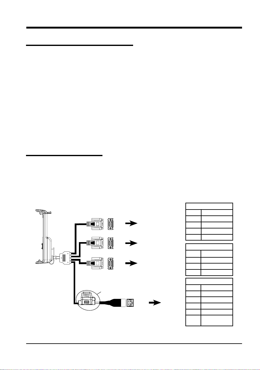
1.2 Electrical connections
G7 Farmnavigator is provided with a bracket and a wiring with connectors to ensure an easy and
safe installation on your tractor.
Wiring harness consists of a 2A protection fuse.
The supply voltage must be within the range 10-35 Vdc
Follow the instructions included in the package.
Figure 1.2.a - Electrical connections
AvMap G7 Farmnavigator – User Manual
6
9
6
9
6
9
2A Fuse
P5 PIN-OUT
1
P5
5
1
P4
5
1
P3
5
GPS antenna
Controller
Generic device
PIN n° Function
2 GPS TX
3 GPS RX
4 GPS VCC
5 GPS GND
P4 PIN-OUT
PIN n° Function
2 DEVICE 2 TX
3 DEVICE 2 RX
5 DEVICE 2 GND
P3 PIN-OUT
PIN n° Function
P2
PWR +
PWR -
Power
supply
2 DEVICE 1 TX
3 DEVICE 1 RX
4 DEVICE 1 VCC
5 DEVICE 1 GND
EXTERNAL
9
ALARM
5
Page 6
1.3 How to install Turtle Smart antenna
The procedure described below refers to Turtle Smart antenna, since it is entirely produced by AvMap
and it is the most common type of antenna used by our clients. (Please, contact the assistance if you
need clarications about the installation of third-party antennas).
Turtle Smart is provided with three magnets which ensure a quick installation on a ferromagnetic
surface.
1.3.1 How to connect Turtle Smart antenna to G7 Farmnavigator
Turtle Smart antenna is provided with a 9-pin serial cable which transfers data and power supply
between G7 Farmnavigator and Turtle Smart antenna.
Turn o the device, and connect the 9-pin serial cable to the cable located on the bracket, marked
with “GPS Antenna”.
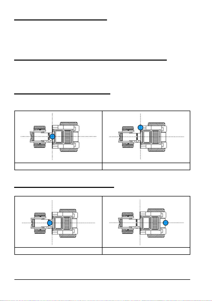
1.3.2 Antenna position– Transverse axis
The antenna must be located in the exact centre of the tractor. Carefully measure the exact centre
of the tractor to determine the central axis.
YES NO
Table 1.3.a How to install the antenna - Transverse Axis
1.3.3 Antenna position - Longitudinal axis
It is advisable to locate the antenna as close as possible to the front steering axles.
YES NO
Table 1.3.b How to install the antenna – Longitudinal Axis
6
AvMap G7 Farmnavigator – User Manual
Page 7
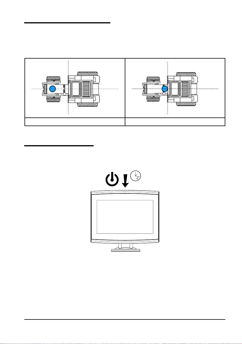
1.3.4 Antenna position – Height
The eects of antenna height have to be considered in case of jobs on steep sloping grounds. In
these cases, it is recommended to install the antenna on the front of the tractor so as to reduce tilt
and oscillation error.
In all other cases (jobs on the level ground), the antenna may be positioned on the top of the tractor.
Slope Flat
Table 1.3.c How to install the antenna – Height
1.4 Turning the device on
Before turning G7 Farmnavigator on, make sure the display is connected to the bracket. Check that
the bracket is rmly anchored to the tractor and that the power cable is plugged into 12V socket.
Figure 1.4.a Turning on the display
1. Press and hold the button located in the upper right corner of the display for 2 to 3 seconds;
2. Once the device is on, the logo will be displayed on the screen;
3. Once loading is completed, a warning section will appear on the screen. Please, read it
carefully and press OK to accept and continue, and open the main menu.
NOTE: when turning the device on for the rst time, you must select the language.
AvMap G7 Farmnavigator – User Manual
7
Page 8
To turn the display o:
1. Press and hold the power button for 2 to 3 seconds;
2. Press “YES” to turn the device o.
It is possible to reset G7 Farmnavigator if the device cannot be normally turned on/o. The reset
button is located at the left of the power button, below the plastic cover.
Figure 1.4.b Reset the device
How to reset the device:
1. Press the button;
2. Wait for the device to reset.
ATTENTION: a reset of the device might cause data loss.
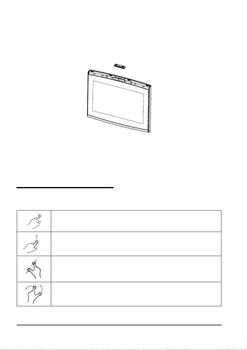
1.5 How to use multi-touch display
G7 Farmnavigator is provided with a multi-touch display which allows you to perform specic actions
with your ngers.
Tap the screen to select a button from the menu.
Move your nger to scroll through the menu or scroll through the pages.
Slide the ngers closer together or further apart to zoom in or zoom out the eld.
Touch the screen with two ngers simultaneously to rotate the eld.
Table 1.5.a Touch screen gestures and movements
8
AvMap G7 Farmnavigator – User Manual
Page 9
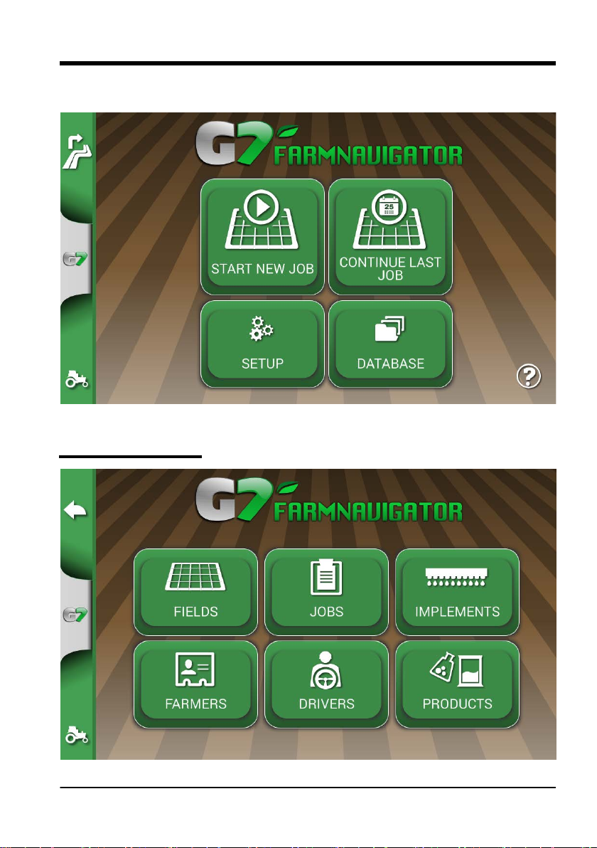
2. Main menu and basic operations
Below are the basic operations for the creation of a new job, system settings, the creation of a new
implement and working methods.
Figure 2.0 - Main menu
2.1 DATABASE menu
AvMap G7 Farmnavigator – User Manual
Figure 2.1.a DATABASE menu
9
Page 10
Farmnavigator functions are designed to save and precisely organize all the information relating to each
single job. It is advisable to enter data from the outset, in order to fully exploit all the advantages of this
technology.
Through DATABASE menu, it is possible to manage all your data (insertion, visualization, editing,
elimination, exportation).
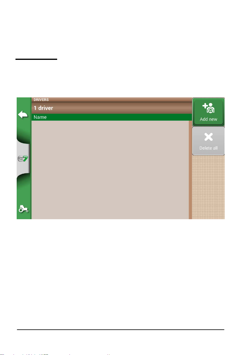
2.1.1 DRIVERS
It is possible to save all DRIVERS name.
1. Select “Add new”;
2. Enter the name, and select “OK”;
3. Tap the green arrow in the upper left corner of the screen to go back to the previous page.
10
Figure 2.1.b Add a new driver
AvMap G7 Farmnavigator – User Manual
Page 11
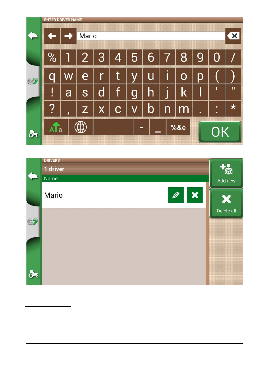
Figure 2.1.c Driver name
Figure 2.1.d List of drivers
2.1.2 FARMERS
It is essential to save FARMERS name. FARMERS refer to all customers or landowners. If a company has
the ownership of all the worked lands, insert the name of the company in the FARMERS section.
1. Select “Add New”;
AvMap G7 Farmnavigator – User Manual
11
Page 12
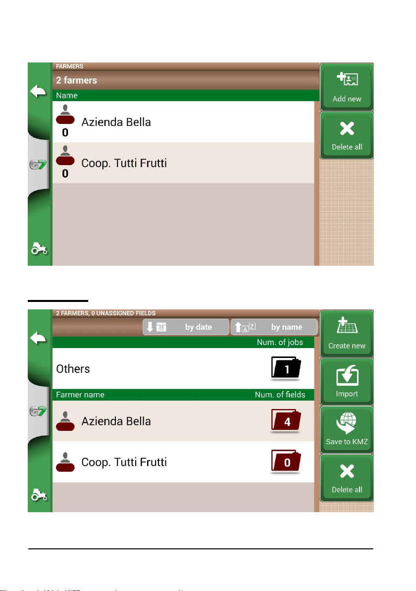
2. Insert the name, and select “OK”;
3. Tap the green arrow in the upper left corner of the screen to go back to the previous page.
Figure 2.1.e List of farmers
2.1.3 FIELDS
12
Figure 2.1.f List of elds associated with farmers or others
AvMap G7 Farmnavigator – User Manual
Page 13
It is possible to collect and save all the parcels of land worked or that must be worked. FIELD are associated
with FARMERS:
1. Select farmer name;
2. Select “Add New”;
3. Insert the name, and select “OK”;
4. Tap the green arrow in the upper left corner of the screen to go back to the previous page.
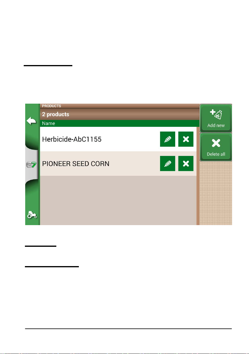
2.1.4 PRODUCTS
G7 Farmnavigator allows you to create a list of products and save their use after each activity.
1. Select “Add New”;
2. Insert the name, and select “OK”;
3. Tap the green arrow in the upper left corner of the screen to go back to the previous page.
Figure 2.1.g List of products
2.1.5 JOBS
Jobs are created automatically through the procedures described below.
2.1.6 IMPLEMENTS
In the IMPLEMENTS page, it is possible to create and congure all the implements that will be used with
G7 Farmnavigator.
1. Select “Add New”;
2. Insert the name, and select “OK”;
AvMap G7 Farmnavigator – User Manual
13
Page 14
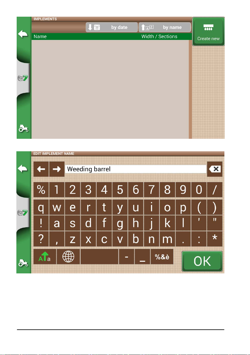
Figure 2.1.h IMPLEMENTS menu
Figure 2.1.i Implement name
3. If active, select the external controller type. Select “No section control” to use the implement
without section control.
14
AvMap G7 Farmnavigator – User Manual
Page 15
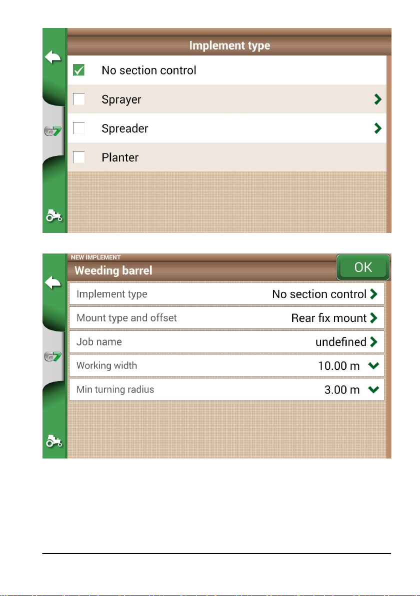
Figure 2.1.j External control unit connection
Figure 2.1.k Implement setting
4. Select “Assembling type and oset”;
5. If the implement is mounted, tap “REAR FIX MOUNT”;
- Oset 1 refers to the distance between the posterior axle and the implement operating point.
- Oset 2 refers to an eventual misalignment between the implement and the centre of the tractor.
AvMap G7 Farmnavigator – User Manual
15
Page 16
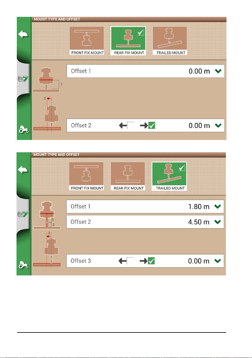
Figure 2.1.l Rear x mount implement
Figure 2.1.m Trailed mount
6. In case of towed implement, select “TRAILED MOUNT”;
- Oset 1 is the distance between the posterior axle and the junction;
- Oset 2 is the distance between the junction and the implement operating point;
- Oset 3 refers to a possible misalignment between the implement and the centre of the tractor;
16
AvMap G7 Farmnavigator – User Manual
Page 17
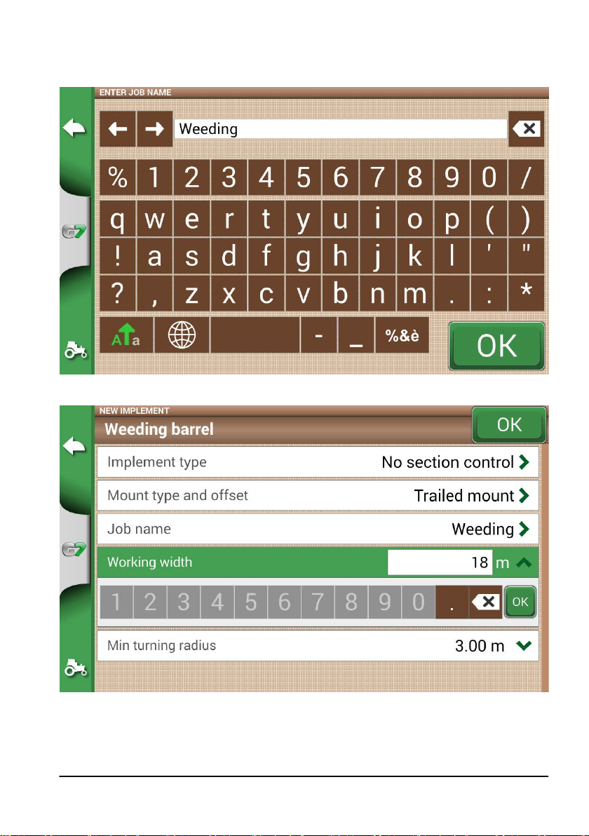
7. Tap the green arrow in the upper left corner of the screen to go back to the previous page;
8. Select “Job type” to enter the type of job performed by the implement;
Figure 2.1.n Implement main activity
Figure 2.1.o Working width setting
9. Tap “Working width”, insert implement width, and select “OK”;
10. Tap “Minimum turning radius” and insert the turning value indicated in the tractor registration
certicate, and select “OK”;
AvMap G7 Farmnavigator – User Manual
17
Page 18
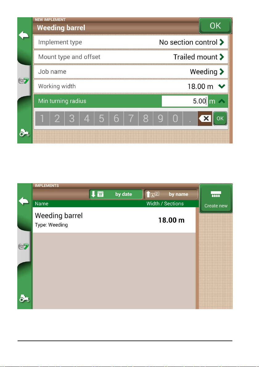
Figure 2.1.p Tractor minimum turning radius setting
11. Select “OK” in the upper left corner of the page to conrm;
All the information needed are now entered. From the database menu, it is always possible to add, edit and
delete the information entered.
Figure 2.1.q List of saved implements
18
AvMap G7 Farmnavigator – User Manual
Page 19
2.2 New job menu
To create a new job in fast mode, that is without entering all the working parameters and starting
with your job:
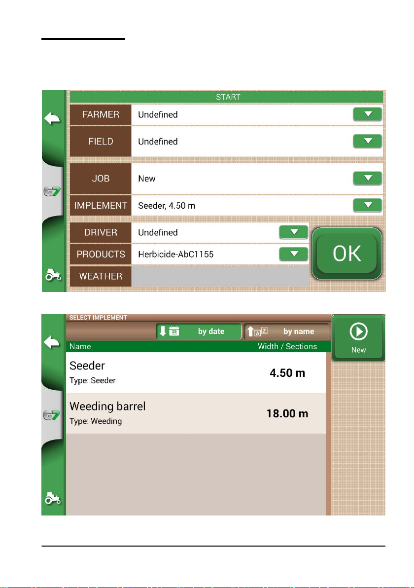
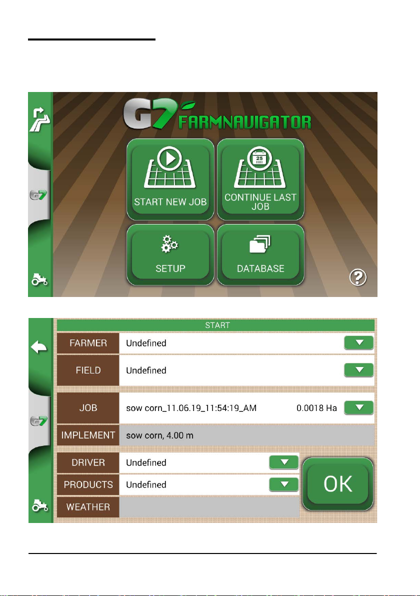
1. Select “START NEW JOB”;
2. Select the implement from the “IMPLEMENT” line, tapping the downward green arrow;
Figure 2.2.a Start new job page
AvMap G7 Farmnavigator – User Manual
Figure 2.2.b List of implements
19
Page 20
3. Select the name of the implement;
4. Select “OK” to switch to the job page;
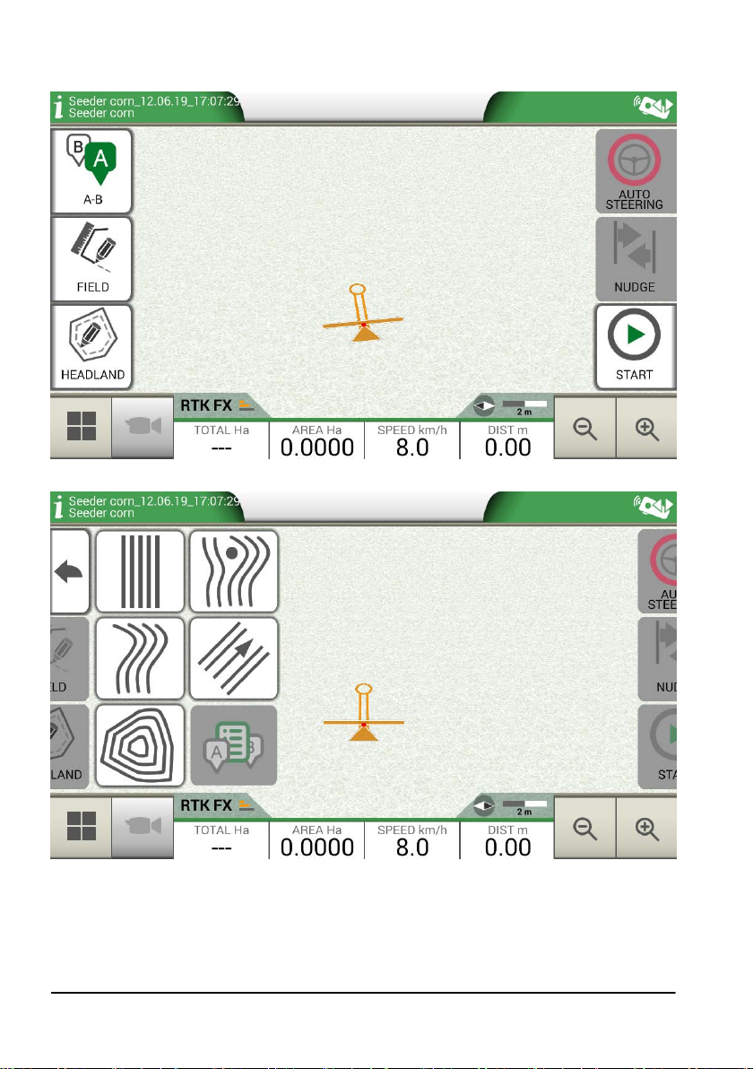
Figure 2.2.c Job page
Figure 2.2.d Job type selection
5. Select “A-B” to start the job;
6. Select the type of guidelines, for example A-B parallel guidelines;
20
AvMap G7 Farmnavigator – User Manual
Page 21
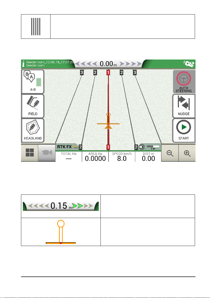
A-B parallel guidelines
Tap this icon to work with A-B parallel guidelines.
Table 2.2.e A-B straight lines
- Tap the icon to save point A;
- Proceed few metres straight ahead to save point B;
Figure 2.2.f Parallel lines
7. A-B lines are now created;
8. Follow both the line direction displayed at the top of the page and the guidance cursor to maintain
the correct trajectory of the vehicle.
Tabel 2.2.g Distance from guideline and smart cursor
AvMap G7 Farmnavigator – User Manual
Distance
Distance between the tractor and the A-B guideline.
The green cursor indicates how to turn the steering
wheel so as to correct the trajectory.
Smart cursor
The smart cursor is provided with two lines. It
helps user to maintain the tractor aligned with the
direction of the A-B guideline.
21
Page 22
2.3 Continue last job menu
G7 Farmnavigator allows you to continue the last job, accessing it directly from the Main Menu:
1. Select “CONTINUE LAST JOB” from the main menu;
2. This page shows you all the information about your last job. Select “OK” to conrm;
Figure 2.3.a Main menu – Continue last job
22
Figure 2.3.b Last job conrmation page
AvMap G7 Farmnavigator – User Manual
Page 23
3. The project will be loaded. Now it is possible to continue the job.
Figure 2.3.c Last job and latest position visualization
2.4 Configuration menu
From the “CONFIGURATION” menu, it is possible to access dierent settings, parameters and customization.
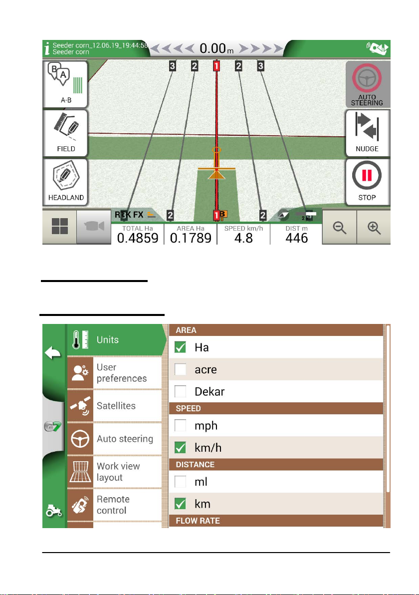
2.4.1 Units of measurement
AvMap G7 Farmnavigator – User Manual
Figure 2.4.a Units of measurement
23
Page 24
It is possible to congure unit of measurement for area, speed and distance:
1. Tap on “CONFIGURATION” > “Units”;
2. Select the unit that you need to modify;
3. Select the required unit of measurement;
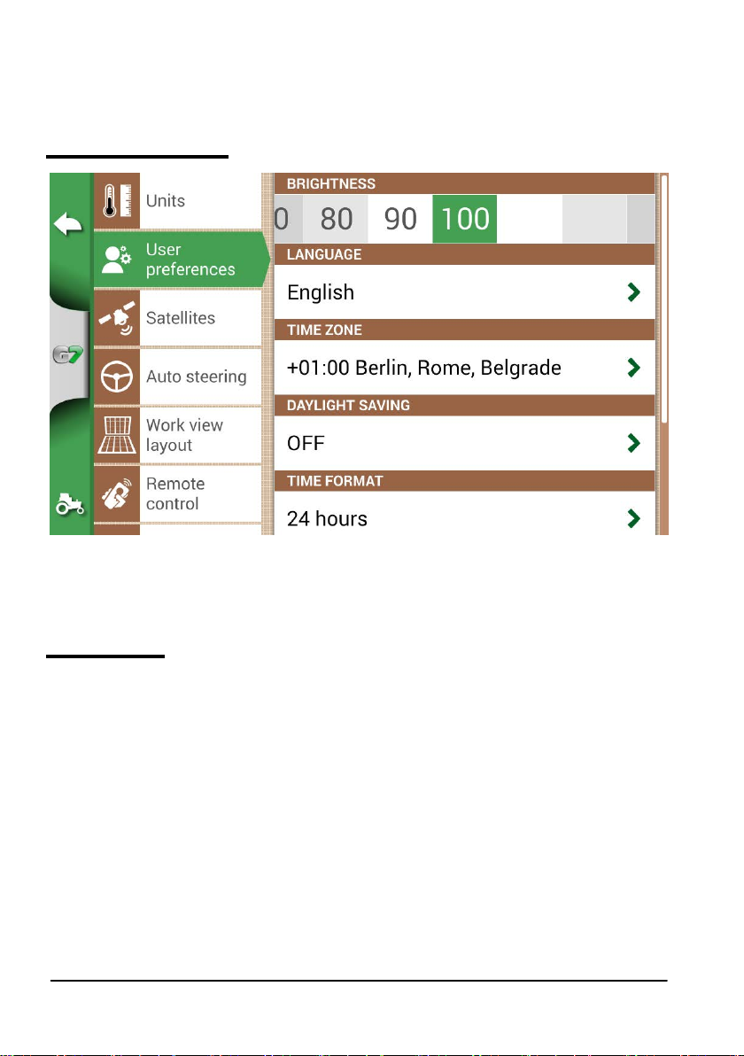
2.4.2 User preferences
Figure 2.4.b User preferences page
It is possible to congure and edit user preferences:
1. Select “CONFIGURATION” > “User Preferences”;
2. Select the preference than has to be changed and tap the arrow to change it.
2.4.3 Satellites
This page allows you to check the satellites status and change the settings of the GNSS receiver. GNSS
settings may vary depending on the type of GNNS, for this reason the menu may look dierently from
one type to another.
1. Select “CONFIGURATION” > “Satellites”;
- MINIMUM SPEED LIMIT: This value should be close to 0 km/h only if you are using a high precision
receivers (RTK).
ATTENTION: It is strongly recommended to modify this parameter only after receiving conrmation from
technical support;
- REVERSE DETECTION: this feature indicates if the tractor is driving forward or in reverse. When
active, if the direction of travel is detected incorrectly, tap “Forward Direction” to restore normal
functioning;
- SATELLITES INFORMATION: this page displays the map of satellites and their signal strength. In
order to guarantee a correct functioning of the device, the majority of the satellites must be coloured
in green. Otherwise, wait at least 20 minutes in an open-space and dust the antenna with a wet rag.
24
AvMap G7 Farmnavigator – User Manual
Page 25

Figure 2.4.c Satellites conguration page
2.4.4 GPS antenna position on the tractor
This parameter refers to the position of the GPS antenna in relation to the posterior axel of the tractor.
1. Enter the distance value accurately and select “FORWARD” if the antenna is located in front of the
axel; select “BACKWARD” if it is located behind the rear axle.
Figure 2.4.d Antenna position in relation to rear axle
AvMap G7 Farmnavigator – User Manual
25
Page 26

2.4.5 Auto-Steering (for G7 Plus only)
Auto-Steering menu allows you to access G7 Farmnavigator settings when it is connected to AutoSteering system.
1. Select “SETTINGS” > “Auto-Steering”;
Figure 2.4.e Auto-Steering conguration page
In this page it is possible to nd:
- ECU INFO: information about ECU-S1 steering controller connected to G7 Farmnavigator;
- AUTO-STEERING: it is possible to open Auto-Steering advanced menu settings
ATTENTION: this feature is limited to expert users. An incorrect conguration leads to a malfunction of the
Auto-Steering system;
- NUDGE STEP: it is possible to congure a default displacement value for the function “Move”;
- SYNC JOB START/STOP: set this function “ON” and select Auto-Steering button to start colouring
the worked area.
2.4.6 Work view layout
Work view layout menu allows you to edit the map view.
1. Select > “SETTINGS” > “Work view Layout”;
- MAP VIEW: select 2D to have a view from above or 3D for a perspective view;
- DAILY BACKGROUND: allows you to change the background colour of the map;
- SCALE GRID: it allows you to create a grid on the background. It is possible to congure grid size
manually.
NOTE: grid orientation always refers to geographical North.
26
AvMap G7 Farmnavigator – User Manual
Page 27

Figure 2.4.f Work view layout conguration page
2.4.7 Remote control (for G7 Plus only)
Remote control menu allows you to congure the supplied remote control.
1. Select “SETTINGS” > “Remote control”
Figure 2.4.g Remote control setting page
Remote control allows you to have a quick access to the main functions, such as opening the main menu,
AvMap G7 Farmnavigator – User Manual
27
Page 28

starting or pausing jobs, enabling or disabling Auto-Steering system, placing a mark on the map (on
obstacles, on specic points, etc.).
To connect the remote control, make sure that it is within a range of a few metres from G7 Farmnavigator
and insert batteries into the slot. Then:
1. Select “SETUP” > Remote control;
2. Select “REMOTE CONTROL RECEIVER” and Press “ON” to turn it on;
3. Select “PIN” and enter the PIN code given on the back of your remote control;
PIN
Figure 2.4.h Remote control
4.Press the middle button (navigation arrow) of your remote control, to connect the display to the remote
control. Once connected, select “REMOTE CONTROL INFO” to check connection status, battery status
and rmware version.
The functions of the remote control buttons can only be used in job page. On details:
8
1
Menu
1
Press it to open the main Menu.
Cycle
3
If the camera is connected, select
it to open the camera visualization.
28
2
3
4
Back
2
Press it to go back to the previous page.
Mark
4
Press it to mark an obstacle on the map.
7
6
5
AvMap G7 Farmnavigator – User Manual
Page 29

Start/Stop
5
Press it to start/stop colouring the
worked area on the map.
Zoom in/zoom out wheel
7
Use the lateral wheel to zoom in
or out the map.
Table 2.4.i Remote control functions
Setting
6
Press it to open set up page.
Nudge control
It allows you to move the line to follow, moving
8
the remote control to the right or to the left.
2.4.8 Wireless connectivity (for G7 Plus only)
G7 Farmnavigator is provided with wireless connectivity and it can be connected to a WiFi hotspot. A
dedicated menu allows the conguration of a WiFi network.
1. Select “SET UP” > “WiFi”;
2. Select “ON” to start searching for available networks;
3. Select the network that you want to access;
4. Select “Password” to enter the PIN code;
5. Wait for a moment and conrm the connection. Tap the name of the network to check
connection status and IP address information.
6. Select “FORGET” to disable automatic WiFi connection.
Figure 2.4.j WiFi conguration page
2.4.9 Mirror Control (for G7 Plus only)
Install the app Mirror Control to control G7 Farmnavigator with your smartphone or tablet. This app
allows you to use the display of your Android or Apple device as if it was G7 Farmnavigator display.
AvMap G7 Farmnavigator – User Manual
29
Page 30

Figure 2.4.k Mirror Control conguration page
It is possible to connect G7 Farmnavigator to a smartphone or tablet via WiFi network, only if G7
Farmnavigator and the smartphone or tablet are connected to the same router.
1. Select “SETTINGS” > “Mirror-Control” > “ON”;
2.4.10 System Information
Figure 2.4.l System Info page
This page summarizes all the information about the device. On the right side of the page, there are
30
AvMap G7 Farmnavigator – User Manual
Page 31

four buttons.
G7 Plus allows you to search for software updates automatically by selecting “Check for updates” button.
In order to check for updates, you need to connect the device to a WiFi network.
1. Select “SETTINGS” > “System Info”
AvMap G7 Farmnavigator – User Manual
31
Page 32

3. Job page
The Job page shows all the information and functions needed during your work activity.
Figure 2.4.a Job main page
3.1 Current job information
3.1.1 Job name
Job and implement names appear at the upper left corner of the page. Touch “i” to directly access
detailed information about your job.
File and implement name description
Table 3.1.a Job name
3.1.2 Connected devices
At the upper right corner of the screen, there are the icons that identify the type of devices connected
to G7 Farmnavigator.
32
Devices connected to G7 Farmnavigator
Connected and working remote control
AvMap G7 Farmnavigator – User Manual
Page 33

Connected and working WiFi
External third-party device connected and enabled for automatic
sections control
Auto-Steering system connected and enabled for the steering
wheel control
Table 3.1.b Connected devices
3.1.3 Antenna precision and reception
At the bottom left corner of the page, it is possible to see the reception and precision status of the
antenna connected to G7 Farmnavigator.
Description of antenna reception status and signal quality
Figure 3.1.c Antenna reception and precision status
There are dierent levels of accuracy of the antenna:
RTK FX Centimetre accuracy, maximum level of precision possible.
RTK FT
DGPS
3D/SPS Low accuracy, it is not suitable for any type of job.
NO GPS
If the antenna icon (Figure 3.1.c) is green in all its parts, the receiving conditions are perfect.
Otherwise, wait a few minutes, clean the antenna and get the device away from metal obstacles or
dense vegetation.
Decimetre accuracy, very high precision level. It does not t for those jobs which
require 1-2 centimetres precision.
Sub-meter accuracy, middle level of accuracy, perfect for the majority of job. It
includes the correction provided by geostationary satellites SBAS (EGNOS,
WAAS, etc.).
No GPS signal, the antenna is disconnected or it is in a place where there is a total
coverage of the signal (inside a building).
Table 3.1.d Antenna precision level
3.1.4 Zoom Level and compass
At the bottom right corner of the screen, it is possible to see both zoom level and the compass that
indicates the direction of the tractor.
The compass is oriented according to tractor’s progress. The black
tip of the compass indicates the North. The scale bar indicates the
zoom level applied to the map.
Table 3.1.e Zoom and compass
AvMap G7 Farmnavigator – User Manual
33
Page 34

3.1.5 Area, speed, distance
At the bottom of the screen, it is possible to see all the information about distance, speed, worked area
and total area.
Information about area, speed and
distance during work.
Table 3.1.a Area, speed, distance
The information displayed may vary if G7 Farmnavigator is connected to third-party devices. Long tap
area value icon (second box starting from the left) to open a selection menu and change the information
displayed.
3.2 Operative functions during job
3.2.1 Start/stop
START/STOP function enables you to draw or not a worked area.
- Press “START” to draw a green area of the same width as the implement and to count it in the
worked area;
- Press “STOP” to interrupt colouring and suspend the counting of the area.
NOTE: START/STOP function can be also used in case of refuelling pauses during job.
START
Tap this icon to start working and colouring the worked area.
STOP
Tap this icon to interrupt colouring of the area.
Table 3.2.a Start/Stop functions
3.2.2 A-B lines
When you start a new job, tap A-B to have access to dierent types of guidelines. More specically:
A-B Parallel lines
Tap this icon to work with A-B Parallel lines.
Once you tap the icon, the point A will be saved. Proceed few metres straight ahead
to save point B.
A-B Contour guidelines
Tap this icon to work with A-B Contour guidelines.
Once you tap the icon, the point A will be saved. Proceed few metres straight ahead
to save point B. It is essential to correctly set “Minimum Turning radius” in the
implement settings page.
Pivot Guidelines
Tap this icon to work with pivot guidelines.
34
AvMap G7 Farmnavigator – User Manual
Page 35

A-B Adaptative contour
Tap this icon to work with A-B Adaptative contour.
Once you tap the icon, the point A will be saved. Proceed few metres straight
ahead to save point B.
With this type of guideline, the last track drawn will be copied. It always provides
a 180° turn at the end of the eld.
Point A + Direction
Tap the icon to save point A.
In the end, the direction of the tractor will be displayed and it can be conrmed
or edit.
A-B lines list
This icon is active when the eld is selected and if there are A-B guidelines
already associated to that eld.
Table 3.2.b A-B line types
Figure 3.2.a A-B guidelines
Once A-B lines are dened and created, the icon will indicate the type of guideline which is currently
active during your job.
A-B Parallel A+ Heading
Table 3.2.c Icon with A-B guideline type
During the job, tap A-B icon to access additional functions concerning A-B lines cancellation,
change, or displacement.
AvMap G7 Farmnavigator – User Manual
35
Page 36

Figure 3.2.b Operating functions during job activity
Below is a list of all the functions available:
Magnet
Move A-B lines according to the antenna position.
Streets
Move A-B guidelines some metres away from the antenna position. The
maximum displacement permitted is equal to half of implement width.
Shift cancellation
Delete shift and reset original A-B guidelines.
A-B guidelines list
If active, it shows the list of A-B guidelines saved and used in the eld.
Delete A-B lines
This feature allows you to delete the A-B guideline created in the eld. The
area already worked and coloured in green will not be deleted.
Table 3.2.d Functions available in the A-B menu
36
AvMap G7 Farmnavigator – User Manual
Page 37

3.2.3 Field
In order to dene a eld, go along the eld perimeter and activate eld registration mode.
The term eld refers to the physical perimeter of the eld. “FIELD” function allows you to save the
position of the eld. It is possible to carry on the activities even during the measurement of eld
boundaries. It is important to take into account that G7 Farmnavigator calculates the position of the
eld boarders according to the width of the chosen implement.
- Move to the edge of the eld;
- Select “START” if you are working the area during the registration of the eld boundaries;
- Select “FIELD” and move along the eld perimeters;
Figure 3.2.c Creation of a new eld
- Tap “FIELD” again, when you are in close proximity to the starting point so as to nish
recording;
AvMap G7 Farmnavigator – User Manual
37
Page 38

Figure 3.2.d Closing the eld perimeter
- The eld takes the same name dened during the new job creation page. Tap “EDIT” if you
want to modify it;
Figure 3.2.e Field name modication
- Field boundaries are now saved and stored in memory
NOTE: It is possible to locate the eld on the same perimeters next year only by using an RTK
instrumentation.
38
AvMap G7 Farmnavigator – User Manual
Page 39

Once the eld is dened, there are other features which allow you to visualize, edit or delete eld
boundaries. Tap “FIELD” to access these features:
Edit/continue eld registration
It allows you to modify eld boundaries already dened by adding or modifying
one of its part.
Enable/disable eld view
Tap this icon to enable or disable the contour view of the eld from the map.
Delete eld boundaries
Delete eld contour.
Table 3.2.e Field functions detail
3.2.4 Headlands
This feature is very useful for determining the contour of the worked area. Dene the eld to use
this function.
Take the following steps to activate headland:
- Select a eld from the list and create a new job;
- Move to the edge of the eld;
Figure 3.2.f Headland, start a new row
AvMap G7 Farmnavigator – User Manual
39
Page 40

- Select headland key, named “HEADLAND”, and set the width of the headland that must be a
multiple of implement width;
- An area which corresponds to the headland will be displayed on the map.
Figure 3.2.g, Headland width conguration
Figure 3.2.h Headland, area
Headland has dierent functionalities:
- It allows to dene the area of the contour to be worked or already worked;
40
AvMap G7 Farmnavigator – User Manual
Page 41

- In case of automatic sections control, it avoids that the product will be sprayed on the headland;
- It allows you to activate Auto-Steering system along the headland path (eld contour).
Tap “HEADLAND” to enable all these functionalities. Four dierent icons will be displayed:
Headland active
It allows you to open sections automatically on the headland. It shows the path
tracking for Auto-Steering;
Headland disabled
It prevents the opening of the sections automatically inside the headland
Headland inactive
Headland is drawn on the screen, the opening of the sections is active and the
path tracking for Auto-Steering is not active;
Delete Headland
Allows you to delete headland and to restore initial eld conditions.
Table 3.2.f Headland specic functions
3.2.5 Obstacles
G7 Farmnavigator allows users to save and view the position of a specic point on the map (e.g.
an obstacle).
- G7 Plus permits you to activate this option only with remote controller.
- G7 Ezy is provided with a specic button on the main menu.
To save the position on a specic point:
- Tap on “MARK”;
Obstacle / Mark
If pressed, it saves the position and it draws a marker on the map
Table 3.2.i Obstacle, point of interest
- On the map, it is possible to see a marker near the selected point.
AvMap G7 Farmnavigator – User Manual
41
Page 42

Figure 3.2.j Obstacle on the map
3.2.6 Auto-Steering system (For G7 Plus only)
G7 Farmnavifator is compatible with Auto-Steering mode. Connect G7 Farmnavigator to an external
device which allows the steering wheel to be activated automatically and keep the tractor on the
guideline.
In the Job page, the button marked as “AUTOMATIC STEERING” allows you to enable and disable
automatic steering.
Automatic steering not available
G7 Farmnavigator is enabled for Auto-Steering but steering device is not
installed or it is not active.
Auto-Steering active but not in use
Touch the red button to enable Auto-Steering.
Auto-Steering active and in use
Touch the green button to disable Auto-Steering.
Table 3.2.g. Auto-Steering buttons
For more detailed tecnical information about Auto-Steering system, check the Installation and
Maintenance Manual.
42
AvMap G7 Farmnavigator – User Manual
Page 43

3.2.7 Nudge
From the Job page, it is possible to move the A-B lines position a few centimetres. In order to do
so, tap “NUDGE”.
Nudge
It allows you to modify A-B line position.
Table 3.2.k Work page, nudge button
Figure 3.2.I Work page, A-B lines movement.
It is possible to insert nudge step, select movement direction or align the lines to the current position
of the tractor.
Set nudge step
Tap this icon to set nudge step in centimetres, e.g. 5 cm.
Move the line to the left
Tap this icon to immediately move the line to the left, for example 5 cm (value
set as nudge step).
Move the line to the right
Tap this icon to immediately move the line to the right, for example 5 cm (this is
the value set as nudge step).
AvMap G7 Farmnavigator – User Manual
43
Page 44

Align the lines
Tap this icon to move the line on the current position of the tractor.
Delete movement
Tap this icon to restore A-B line initial position and remove all the saved
movements.
Go back to the previous page
Tap this icon to close the menu relative to nudge page. The menu will be closed
automatically after 5 seconds of inactivity.
Table 3.2.m Details of nudge functions
ATTENTION: The maximum allowed nudge step is equal to half of the implement width.
44
AvMap G7 Farmnavigator – User Manual
Page 45

4. Advanced operating modes
This chapter describes advanced operative functions.
4.1 Start new job, full mode
To start a new job in full mode, it is necessary to insert all the information required for a correct
registation of a new job:
1. Select “START NEW JOB”;
2. At “FARMER” line, tap the downward green arrow and select the farmer’s name;
3. At “FIELD” line, tap the downward green arrow and select the eld. In case of undened
eld, tap on “Create New” and follow the procedure for inserting a new name;
4. At “IMPLEMENT” line, tap the downward green arrow and select implement’s name;
5. At “DRIVER” line, tap the downward green arrow and select driver’s name;
6. At “PRODUCTS” line, tap the downward green arrow and select the name of the product. It
is possible to select more than just one product for every single job;
7. Select “OK” to go to work page;
8. Tap the “i” located at the upper left corner of the display to edit Job name:
1. Tap the pen icon to modify the text;
2. Select “OK”;
3. Tap on the downward green arrow to go back to the previous page;
4. Tap on “A-B” to start the job.
4.2 Define the field and create new A-B guidelines
During the denition of the eld, it is possible to create A-B guidelines to work the area inside the
eld boundaries. This procedure is to be used the rst time you dene the eld.
In this way an A-B line is created in conjunction with the passage of the tractor on that side of the
eld, avoiding unecessaries overlaps.
- Create a new Job, preferably in full mode.
- Move to the edge of the eld;
NOTE: It is advisable to change the name of the job. In order to do so, tap on “i” located at the top
left corner of the display.
- Tap “START” if the area must be worked during the recording of the boundaries;
- Tap “FIELD” and move along the perimeters of the eld;
- On the Job side, tap “A-B”;
- Select the line type;
- Proceed straight ahead to save point B;
- Tap B and proceed straight ahead to close the contour;
- Tap “FIELD” to complete registration, when you are in proximity to the starting point;
- The eld takes the name dened during the new job creation page. Tap “EDIT” if you want
to modify it;
- Field boundaries will be saved and stored.
AvMap G7 Farmnavigator – User Manual
45
Page 46

Figure 4.2.a Job name modication
NOTE: After one year, the replacement in the same position will be possible only with RTK
instrumentation.
- It is possible to work within the perimeter following the dened A-B lines.
4.3 Working again on defined A-B lines using the same implement
This procedure allows you to avoid redening A-B lines every year. For example; if you need to seed
the same eld with the same seeder every year.
NOTE: this feature is available only with RTK instrumentation.
G7 Farmnavigator allows you to reload a previous job and work it again, recalling the A-B lines used
during the previous activity.
1. Tap “DATABASE”,
2. Tap “FIELD”;
3. Select farmer name;
4. Select eld name;
5. Scroll to the “JOB” line and tap the downward green arrow;
6. Select the job that you want to recall;
7. Select “Start as new” to recall A-B lines saved during the previous activity.
In particular, there are two functions:
Continue
The job will be reloaded and the coloration of the worked area will be maintained.
46
AvMap G7 Farmnavigator – User Manual
Page 47

Restart as new
This function oers you two possibilities:
- start from an existing job.
- create a new job. It is advisable to modify job name tapping “i” at the upper
left corner of the screen.
Table 4.3.b ‘Continue’ and ‘Start as new’ detail
Figure 4.3.a ‘Restart as new’ function
4.4 Working on predefined A-B lines but with another implement
This procedure is useful to avoid redening A-B lines every year. For example, if you have dened
A-B guidelines during planting season and you need to recall them for your treatments next year.
The procedure is the following:
1. Tap “START NEW JOB”;
2. Select the “FARMER”;
3. Select the “FIELD”. It is essential to select the name of the eld used during the previous
activity, so that to recall the A-B lines used in that eld.
AvMap G7 Farmnavigator – User Manual
47
Page 48

Figure 4.4.a Field selection page
4. Select the “IMPLEMENT” (it must be dierent from the implement used in the previous job);
5. Select the “DRIVER”;
6. Select the “PRODUCT”;
7. Tap “OK” to conrm the creation of a new job.
The last job will be reloaded and A-B lines width will be calculated according to the new implement
width.
It is necessary to put the tractor in the same position as for the previous job, by following this
procedure:
1. Tap on “A-B”;
2. Tap on “Magnet” icon. The rst line will be move to the real implement position;
3. In case of error in the positioning, repeat the operation;
4. Select “START”;
5. Proceed with the activity.
4.5 Create more than one A-B line during the same job session
NOTE: this function can be used only if the eld is set.
G7 Farmnavigator allows you to save more than one A-B lines and recall them for further activities.
To save more than one A-B lines within the eld, proceed as follows:
1. Create a new job, select a eld from the list or create a new eld;
2. Start the job and dene an A-B line (e.g. A-B Parallel guidelines);
3. Tap again on “A-B” if you need to create another A-B line (e.g. adaptative guidelines);
4. Tap the “A-B” icon, marked with a red X, to cancel the lines from the display;
5. Tap “YES”. The line will be deleted only from the display, but it is stored in memory;
6. Move the tractor to the new job direction, inside the same eld and the same job;
48
AvMap G7 Farmnavigator – User Manual
Page 49

7. Tap “A-B” icon and select the lines type that must be dened (e.g. Contour guidelines);
8. Move to the point B;
9. At this point, a second A-B line is created.
4.6 Change A-B lines during the same job
ATTENTION: this function can be used only if the eld is set.
If during your activity, there is a need to change A-B lines, proceed as follows:
1. Tap “A-B”;
2. Tap AB List icon.
Figure 4.6.a A-B line change during job
AB list icon.
Table 4.6.b A-B list icon
3. Select the A-B line type that you need to display;
AvMap G7 Farmnavigator – User Manual
49
Page 50

Figure 4.6.c List of A-B lines used in a eld
4. Delete A-B line, tap “YES”. The line will be deleted only from the display, but it is stored in
memory;
Figure 4.6.d Example of a job with more than one A-B line saved
4.7 Move the line to a specific point, “Magnet” function
It is possible to use “Magnet” function to:
- Avoid an obstacle (moat, drain, street) and move to a new parcel of eld without creating a
50
AvMap G7 Farmnavigator – User Manual
Page 51

new A-B line;
- Locate the line on your current position, maintaining A-B direction;
- Reuse A-B lines with an implement which has a dierent width: locate the implement at the
starting point, use the “Magnet” function to move the origin of A-B lines on that point.
To use “Magnet” function:
1. Tap “A-B”;
2. Tap “Magnet”;
Magnet
Move the A-B lines to the antenna position.
Table 4.7.a “Magnet” function
3. A-B lines will be moved to the exact position of the tractor.
4.8 Move A-B line according a precise value, “Street” function
“Street” function allows you to move A-B line according to a precise metrical distance. The
repositioning of the A-B lines starts from the tractor current position.
This function is essential when you need to:
- Leave a precise distance between one A-B line and the other;
- Create “Streets” in sowing area, usually used for irrigation;
- Split the parcel into precise portions.
In order to use “Streets” function:
1. Tap “A-B”;
2. Tap on “Street” icon;
Streets
Move A-B lines few meters away from the antenna position. The maximum
allowed movement is equal to half the width of the implement.
Table 4.8.a ‘Streets’ Functions
3. Set the metrical distance according to which the row will be moved;
NOTE: the distance will be calculated starting from the antenna position (which corresponds to the
position of the tractor);
4. Conrm to apply the movement.
4.9 Connect an external device to control sections
G7 Farmnavigator allows you to connect third-party external devices to make an automatic control
of the section. This feature can be used with implements such as:
- Weeding barrel
- Spreaders
- Planters
In the appendix, there is a list of supported devices.
The procedure to be performed for the correct conguration is as follows:
AvMap G7 Farmnavigator – User Manual
51
Page 52

1. Connect the external device to the G7 Farmnavigator bracket through 9-pin serial port
marked as “CONTROLLER”;
2. Turn both G7 Farmnavigator and the external device on. Any other settings concerning the
external device are not part of this manual;
3. Select “DATABASE” > “IMPLEMENTS”;
4. Create a new implement;
Figure 4.9.a New implement page
52
Figure 4.9.b External implement type selection page
AvMap G7 Farmnavigator – User Manual
Page 53

5. Select which type of external control is connected to G7 Farmnavigator;
6. Scroll through the list and select the connected device;
Figure 4.9.c External device type
7. Wait for a connection between G7 Farmnavigator and the device;
Figure 4.9.d Connection between G7 Farmnavigator and the external device
8. Set the total width divided into sections;
AvMap G7 Farmnavigator – User Manual
53
Page 54

Figure 4.9.e Section conguration: nozzle per section
9. It is possible to set the width of the spray boom either for the number of nozzles per single
section or for the entire section width;
Figure 4.9.f Sections conguration: section width
10. Enter the number of boom sections;
54
AvMap G7 Farmnavigator – User Manual
Page 55

Figure 4.9.g. Number of sections conguration
11. Insert the individual width of each section. Check the total width to avoid errors;
Figure 4.9.h Single section width conguration
Below is an example of 18 metres boom with 5 sections;
G7 Farmnavigator allows you to insert a time value to advance the opening and closing of the section so as to
anticipate the command that must be send to the external device. This value, expressed in seconds, is equal
to the time required by the device to order the opening of the sections and the actual release of product from
the nozzles.
AvMap G7 Farmnavigator – User Manual
55
Page 56

Figure 4.9.i Example of 18 meters bar with 5 sections
Figure 4.9.j Conguration of opening and closing delays of the section
There are other settings, among which the spray boom overlap percentage.
For example, a value of 100% means that the section will be closed in case of total overlapping. A value
of 50% means that the section will be closed when the boom overlaps the total section width by 50%.
56
AvMap G7 Farmnavigator – User Manual
Page 57
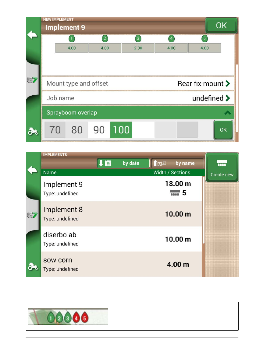
Figure 4.9.k Spray boom overlap conguration
Figure 4.9.I Implements with automatic section control
The implement is now set and displayed in the implement list. An icon identies the implement with active
section control. On the job page, there are icons that show the sections status.
Boom sections status
Green colour indicates that the section is active and
operating.
Red colour indicates that the section is active but turned o.
Table 4.9.m Boom sections status
AvMap G7 Farmnavigator – User Manual
57
Page 58

Figure 4.9.n Boom sections status
G7 Farmnavigator allows you to manually control a section, by tapping the boom sections status.
It is possible to control a section manually forcing the automatic section control. Manual section control
can be congured to either be always active or inactive.
Automatic Status
The section will be turn on and o automatically.
Manual status active
The section is always active. In this case, the drop is green.
Manual status inactive
The section is always inactive. In this case, the drop is red.
Table 4.9.o Section status: automatic and manual
4.10 Using “Planter” to create fields planting layout
G7 Farmnavigator allows you to design and realize planting layout of vines, fruit plants, cultivation and
installation of poles.
In order to activate this feature, it is necessary to use “Planter”. On details:
1. Tap “SETTINGS” > “IMPLEMENTS”;
2. Create a new implement and insert the name;
58
AvMap G7 Farmnavigator – User Manual
Page 59

3. In the implement type selection menu, select “Planter”;
Figure 4.10.a New implement: planter
4. Create a new job and select A-B parallel lines (or A + Direction). Point A will represent the
position of the rst plant;
5. Dene the distance between rows and plants and tap OK to conrm;
Figure 4.10.b Distance between plants and rows conguration page
AvMap G7 Farmnavigator – User Manual
59
Page 60

6. The position of point A and the position of the rst plant are dened;
Figure 4.10.c Field planting layout, point A
7. Proceed to point B and tap “B”. In this way the lines will be created and the plants position
will be marked on the line.
Figure 4.10.d Plant distribution on A-B line
8. When the position of the antenna coincides with the position of the plant, the circle will
change its colour from orange to green;
60
AvMap G7 Farmnavigator – User Manual
Page 61

Figure 4.10.e Plants worked in eld planting layout
9. Further information are displayed at the bottom of job page;
Distance from the plant
This information allows user to know the exact distance between
the antenna position and the next plant (if the sign is positive) or the
distance from the previous plants (if the sign is negative).
Number of worked plants
It allows user to know how many plants have actually been worked
from the beginning of the work.
Table 4.10.f Information about “Planter”
NOTE: third-party accessories will be available for the motions of the tractor, both for Auto-Steering
and for planter automation.
AvMap G7 Farmnavigator – User Manual
61
Page 62

5. Importing and exporting data
5.1 Download a job and view it in the office
G7 Farmnavigator allows you to download a job in KMZ format and visualize it on your Personal
Computer (PC).
NOTE: in order to use this function, Google Earth™ software must be installed on your PC.
To download the le, you need an USB stick, ‘USB cable + Video in’ (G7 Ezy, P/N: K2CYFS0600) or
the ‘USB cable + Video in + Ethernet’ (G7 Plus, P/N: K2CYFS1000).
Figure 5.1.a USB Cabe + Video in
1. Connect USB cable to the G7 Farmnavigator bracket;
2. Insert USB stick in the supplied USB cable connector;
3. Tap “DATABASE” > “JOBS”;
4. Select the job you want to export.
62
AvMap G7 Farmnavigator – User Manual
Page 63

Figure 5.1.b Saving data in KMZ
1. The le will be automatically saved in the USB stick;
2. Connect the USB stick to your PC;
3. Enter the “Export” folder to access the saved job;
4. Double click on the job name;
5. Google Earth™ will be opened (if previously installed).
Figure 5.1.c Job view with Google Earth™
Tap “Info” to see all job information available.
5.2 Import the field boundaries in KMZ format
G7 Farmnavigator allows you to import eld boundaries in KMZ format. This feature is useful when
you want to move eld registration from one G7 Farmnavigator to another or if the eld boundaries
AvMap G7 Farmnavigator – User Manual
63
Page 64

are drawn in your oce using Google Heart™ software.
Create a new folder called “Import” and put it in the USB stick. Inside the folder “Import”, copy the
KMZ les you want to import. Connect the USB stick to G7 Farmnavigator using the supplied cable.
1. Tap “DATABASE” > “FIELD”> “Import”;
2. Select the le that you need to import;
Figure 5.2.a KMZ le import access menu
64
Figure 5.2.b File KMZ selection
AvMap G7 Farmnavigator – User Manual
Page 65

- Tap “Import” and wait for the elds to be imported;
Figure 5.2.c Importing elds from KMZ
- In “FIELD” menu, there is a eld for each imported KMZ le.
Figure 5.2.d Preview of a eld imported from KMZ
5.3 Importing a map in SHP file format
Create a new folder called “Import” and put it in the USB stick. Inside the folder “Import”, copy the
AvMap G7 Farmnavigator – User Manual
65
Page 66

KMZ les you want to import. Connect the USB stick to your G7 Farmnavigator using the cable
supplied.
- Tap “DATABASE” > “CAMPI” > “Import”;
Figure 5.3.a File SHP import menu
- Select the le which you need to import;
Figure 5.3.b SHP le Import
- Tap “Import” and wait for boundaries to be imported;
66
AvMap G7 Farmnavigator – User Manual
Page 67

Figure 5.3.c Import SHP le – work in progress
- All the eld boundaries contained in the SHP le are now visible in “FIELD” menu;
Figure 5.3.d – List of elds loaded from SHP le
- It is now possible to see a preview of each eld;
AvMap G7 Farmnavigator – User Manual
67
Page 68

Figure 5.3.e Example of a eld loaded from SHP le
5.3.1 Create a boundary in SHP file format
There are various software available for creating boundaries and exporting them to SHP le format.
Above is an example of saving eld boundaries in SHP format starting from Google Heart™.
- Drawn a polygon in Google Earth™
Figure 5.3.f Example of a polygon drawn with Google Earth™
- Save the le with “Save place as..”;
68
AvMap G7 Farmnavigator – User Manual
Page 69

- Use one of the online software available to convert a KMZ le into a SHP format (for example;
MyGeodata Cloud);
- Import the SHP le into G7 Farmnavigator following the import procedure (Par 5.2).
Figure 5.3.g SHP le created with Google Earth™
AvMap G7 Farmnavigator – User Manual
69
Page 70

6. Other functions
6.1 G7 Farmnavigator software updates
The updates for G7 Farmnavigator are available every year. Follow the above procedure to update
the software of your device.
6.1.1 Software Update via WiFi (G7 Plus only)
G7 Farmnavigator is provided with an automatic search for available updates when the device is
connected to a WiFi network. To search for software update:
1. Tap “SET UP”> System info > “Check for updates” and wait for the connection;
Figure 6.1.a Software update via WiFi
1. Tap “YES” to download the update;
2. The device restarts in update mode;
3. Tap “UPDATE NOW” to proceed with the installation;
4. Tap “CONTINUE” and wait for the restart;
5. The update is completed and the WiFi network can be turned o.
6.1.2 Software Update via USB
If it is not possible to update the software via WiFi due to the lack of connection or since you have a
G7 Ezy, you have to update the software via USB.
To proceed with the update, you need:
- USB stick (at least 2GB);
- Update le (it is strongly suggested to contact the customer service);
70
AvMap G7 Farmnavigator – User Manual
Page 71

- ‘USB Cable/ Video in’ (g7 Ezy, p/n: K2CYFS0600) or cable USB / Video in / Ethernet’ (G7
Plus, P/N: K2CYFS1000).
Perform the following procedure:
1. Copy the update le from a PC to USB stick;
2. Connect USB cable to the G7 Farmnavigator bracket;
3. Insert USB stick into the USB connector of the supplied cable;
4. Turn G7 Farmnavigator on, the device starts in update mode;
5. Tap “UPDATE NOW” to install the update;
6. Tap “CONTINUE” and wait for the program to start;
7. The update is now completed and the USB stick can be dismissed.
6.2 Video camera
G7 Farmnavigator allows you to connect an external, analogic video camera. There are no settings
to be performed on the software.
6.2.1 Type of supported cameras
G7 Farmnavigator supports analogic cameras with PAL o NTFS format.
The video camera must be provided with a male RCA connector. Power to the video camera must
be supplied externally to G7 Farmnavigator. IP and USB camera are not supported. Power must be
supplied externally.
6.2.2 Connect a video camera
It is possible to connect a video camera to G7 Farmnavigator via the ‘USB cable/Video in’ (G7 Ezy,
P/N: K2CYFS0600) or ‘USB cable / Video in /Ethernet’ (G7 Plus, P/N: K2CYFS1000). The cable is
provided with an analog RCA female video input.
Figure 6.2.a How to connect a video camera to G7 Farmnavigator
6.2.3 Display mode for Video camera
When the camera is properly connected to G7 Farmnavigator, the video camera icon will be
automatically activated on the main page of your job.
- Tap the camera icon displayed on the main page of your job to switch to video mode.
AvMap G7 Farmnavigator – User Manual
71
Page 72

Video camera available
The video camera is recognized and connected.
Video camera not available
The video camera is not connected or not compatible.
Table 6.2.b Camera button
6.3 G7 Navi (Only for G7 Plus)
G7 Navi is an app used for terrestrial navigation. It is available only for G7 Plus and it allows you to
use road navigation function. To switch to this modality:
- In the main page, tap the button located at the upper left side of the page;
72
Figure 6.3.a Access to G7 Navi
- Tap “YES”
AvMap G7 Farmnavigator – User Manual
Page 73

Figure 6.3.b Switch to road navigator conrmation page
6.4 Activate a virtual NMEA output on the “Generic” port
Some third-party devices used on the tractor in complementary mode to G7 Farmnavigator, require
the use of GPS antenna for a correct functioning.
G7 Farmnavigator gives the possibility to generate and share a GPS code in NMEA format to be
sent to a third-party device, without using a second GPS antenna.
Figure 6.4.a Virtual GPS output on the ‘Generic’ port
AvMap G7 Farmnavigator – User Manual
73
Page 74

1. Tap “SETUP” > “Satellites”
2. Tap “NMEA on Generic port” and select “ON”.
6.5 Activate the demo mode
G7 Farmnavigator is provided with a Demo mode, very useful for outdoor demonstrations without
GPS.
To enable the demo mode (Demo):
1. Tap “SETUP” > “System info”> “Start demo mode”;
2. Tap the tractor icon located in lower right corner of the page to switch to the job page.
74
Figure 6.5.a Start demo mode
AvMap G7 Farmnavigator – User Manual
Page 75

Figure 6.5.b Demo mode
ATTENTION: do not use demo mode if the GPS antenna is connected to the connector of the G7
Farmnavigator bracket marked as “GPS ANTENNA”.
To disable Demo mode:
- Tap “Demo mode stop”;
Figure 6.5.c Demo mode stop
AvMap G7 Farmnavigator – User Manual
75
Page 76

7. Contacts/Customer Support
To get rst-level assistance regarding:
- User manual guide
- Warranty
- Replacements, malfunctions
- Repairs
- Updates
Telephone: +39 0585 784044
Mail: support@avmap.it
To get second-level assistance regarding:
- Autosteering
- RTK systems
- Settings
Telephone: +39 334 6033178
Mail: support.farm@avmap.it
76
AvMap G7 Farmnavigator – User Manual
Page 77

8. Appendix
List of third-party devices compatible with G7 Farmnavigator:
Antenna
- AvMap Smart Turtle
- Novatel AgStar
- Novatel Smart6
- Novatel Smart7
- Harxon TS108Pro
Sprayer
- Agral AGSIG
- Agromehanika AG-Tronik
- Bertolini Buono
- Cani CB9
- FarmscanAG UniPOD
- Geoline GeoSystem 260
- MC Elettronica Hydra 590
Spreader
- Bogballe Icon
- Bogballe Zurf
Planter
- Gpskit AgriDrive
AvMap G7 Farmnavigator – User Manual
77
Page 78

Analytic Index
A
Antenna 3, 5, 6, 7, 24, 25, 33, 36, 51, 60, 61, 73, 75
Auto-Steering 3, 5, 26, 28,33, 41, 42, 61
C
Customer Support 3, 76
D
Demo mode 3, 74, 75
Distance from the plant 61
Driver 3, 10, 11, 45, 48
E
Electrical connections 5
Export 5, 62, 63
F
Farmer 11, 12, 13, 45, 46, 47
Field 3, 5, 8, 13, 35, 36, 37, 38, 39, 41, 45, 46, 47, 48, 49, 50,
58, 60, 61, 63, 64, 65, 67, 68
G
Google Earth™ 5, 62, 63, 68, 69
H
Headland 3, 39, 40, 41
Import 3, 5, 37, 62, 63, 64, 65, 66, 67, 69
J
Job 3, 9, 10, 17, 19, 20, 22, 23, 26, 28, 32, 33, 34, 35, 36, 38,
39, 42, 43, 45, 46, 47, 48, 49, 50, 57, 59, 61, 62, 63, 71, 74
Job name 3, 32, 45, 46
K
KMZ 3, 62, 63, 64, 65, 66, 69
M
Magnet 3, 36, 48, 50, 51
Mirror-Control 30
N
Nozzles 54, 55
Nudge 3, 26, 29, 43, 44
Number of worked plants 61
O
Obstacle 28, 41, 42, 50
P
Planter 58, 59, 61, 77
Products 3, 13, 45
R
Remote control 3, 27, 28, 29, 32, 41
S
Satellites 3, 24, 25, 33, 74
Sections 3, 5, 33, 41, 51, 53, 54, 55, 56, 57, 58
Sections control 33, 41
Start 19, 20, 26, 29, 34, 37, 39, 45, 46, 47, 48, 71
Stop 3, 26, 29, 34, 75
Streets 36, 51
T
Total area 34
U
Units 3, 23, 24
Updates 3, 31, 70, 76
USB 3, 62, 63, 64, 65, 66, 70, 71
User preferences 3, 24
V
Video camera 3, 71, 72
W
Worked area 26, 29, 34, 39, 46
Working width 17
Work view layout 3, 26, 27, 78
Z
Zoom 3, 8, 29, 33
Page 79

Page 80

MAG7XAM0AE010
ÑMAG7XAM0AE0109Ó
 Loading...