

Page 1

Your journey, Our technology
User and Installation Manual
Product model number: UX0EMS10AM
Software: version 1.1.0R or more recent
Firmware: version 1.1.0R or more recent
IMPORTANT: Before using this manual check if your Engine product model number
corresponds to the above model number.
Page 2

Page 3

AvMap EngiBOXINDEX
DISCLAIMER & WARNINGS
The information displayed by the EngiBOX is not certied for use for VFR or IFR ights.
The EngiBOX is meant as an aid to VFR ight and is not a substitute for certied instruments.
All critical information is presented for reference only and must be veried by the user.
The EngiBOX is not a substitute for on-board instruments.
The pilot in command assumes total responsibility and risk associated with the use of this device and remains
solely responsible for ying in safe conditions. AvMap disclaims any liability deriving from an improper use of
the device, in a way that may violate the ight and navigation rules, regulations and safety.
1. Overview 4
2. Installation 6
2.1 Mechanical installation 6
2.2 Connections & wiring 8
3. Initialization and First Use 12
3.1 Initialization procedure 12
3.2 First Use 13
4. How to operate the unit 14
4.1 EngiBOX Data views 14
4.2 Graphs 17
4.3 Clock page 18
5. Menu 19
5.1 Settings 19
5.2 Alarms 20
5.3 Export Data 20
5.4 About 21
6. Software update 22
7. EngiBOX App 23
7.1 App installation 23
7.2 Download data for analysis and instant support 23
8. EngiBOX Web Portal 24
9. Technical Specications 25
Appendix: Engine warning and alarm limits
27
Page 4

4 - User and Installation Manual
AvMap EngiBOX
1. Overview
EngiBOX is an Engine Monitoring System (EMS), developed especially for Rotax Engines,
displaying the engine parameters with an update rate of ve times per second and recording
160 hours of data in the internal memory. It is a rugged and reliable system designed for
xed panel installation.
Rotation knob
Figure 1
microSD slot
Note: For connection specications see Chapter 2.
microSD card
A microSD card is provided together with the Engibox. The microSD card is a blank card
without data preloaded. The microSD card should be used for software updates and export
logged data from the EngiBOX to the microSD card.
Note: For more details see Chapter 4.
Rotation knob
Pressing the rotation knob allows to conrm a selection, while rotating the knob allows to
change selection.
EngiBOX connection board:
• 1 x Power input 10-35 VDC, free wire connection
• 4 x Thermocouple sensor input
• 2 x Resistance thermometer sensor input
• 1 x Oil pressure sensor input
• 1 x RPM pick-up
• 1 x Serial connection
• 1 x Manifold pressure sensor
• 1 x Alarm output
Connection board
Page 5

User and Installation Manual - 5
AvMap EngiBOX
Note: Software 1.1.0R does not support serial connection and alarm out.
Compatible Engines
• 2 stroke Air cooled: Rotax 447 UL SCDI, Rotax 503 UL DCDI
• 2 Stroke Liquid cooled: Rotax 582 UL DCDI, Rotax 618 UL DCDI
• 4 Stroke Liquid cooled: Rotax 912 DCDI series, Rotax 912S DCDI series, Rotax 914
DCDI series
EngiBOX displays:
• Exhaust Gas Temperature (EGT)
• Revolutions Per Minute (RPM)
• Manifold Pressure (MAP)
• Oil Pressure (OIL P)
• Oil Temperature (OIL T) / Air Temperature (AIR T)
• Cylinder Head Temperature (CHT) / Coolant Temperature (CT)
• Hobbs meter
EngiBOX measures the engine parameters to warn you instantly if any measurement
exceeds the engine limits and registers instantly the data on the internal memory.
The registered data can be either exported to the micro SD card provided along with the
product or send to the EngiBOX Web Portal through the EngiBOX mobile app. In this way,
data can be analyzed from home and be shared with the engine service center to receive
instant support.
Further EngiBOX features:
• Wizard to initialize the engine,
• Parameters displayed in two alternative views: graphic or numeric,
• Graph page to analyze the performance per each engine parameter (last 20 minutes),
• Clock page to show ight time, engine lifetime (Hobbs meter) and time since last
overhaul.
Note: Engine inizialization may not be needed in case unit installation has been already
performed by the engine service center or the aircraft manufacturer.
Page 6
6 - User and Installation Manual
AvMap EngiBOX
2. Installation
The installation procedure is divided in the following steps:
• Mechanical installation
• Connections & wiring
2.1 Mechanical installation
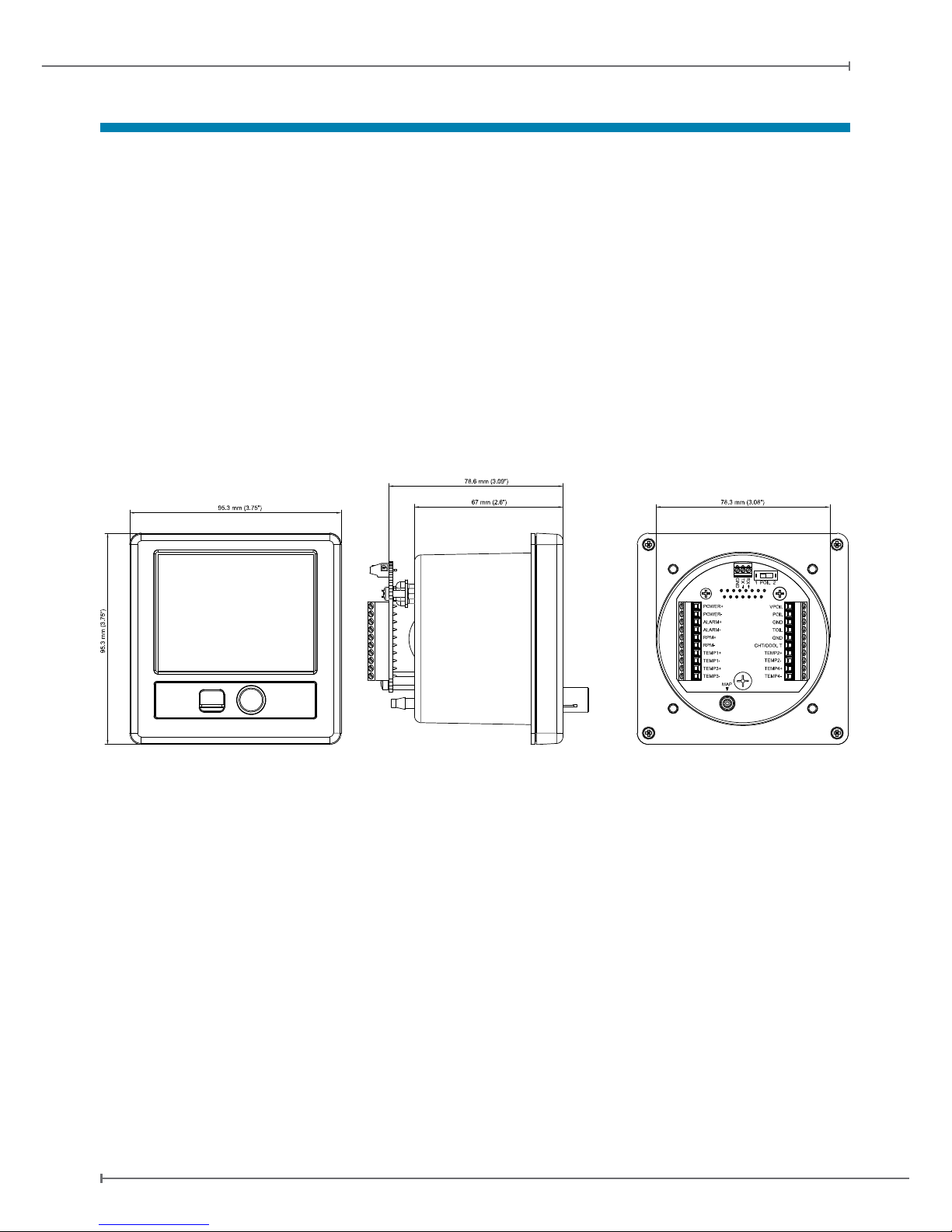
EngiBOX is designed to be installed on the aircrafts instrument panel, in a standard 3 1/8”
(79,5 mm) diameter hole. Make sure you have enough space on the front and behind the
cockpit panel to install the EngiBOX.
Check the EngiBOX main dimensions reported in Figure 2.
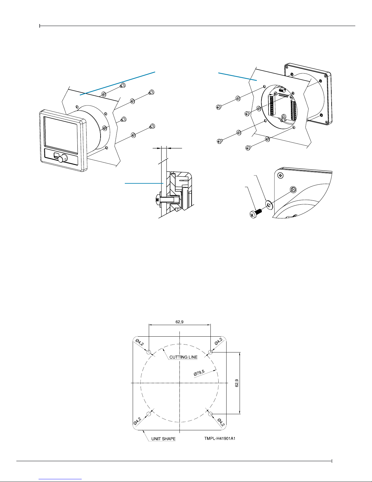
The instrument has to be installed from the front of the panel and screwed from behind the
panel according to Figure 3.
The screw length that need to be used for panel installation depend on the panel thickness
and is based on the following formula:
5mm ≤ l - t ≤ 8mm
l = length of the screw
t = thickness of the panel
Figure 2
Page 7
User and Installation Manual - 7
AvMap EngiBOX
Use the screws and metal washer included in the box for standard panel thickness of up to 3mm. For
thicker instrument panels, use longer screws and use the formula to choose the right screw length.
3
METAL WASHER
M4X08 SCREW
Figure 3
Figure 4
IMPORTANT: Make sure you respect the screw length formula to avoid damaging the
plastic of the EngiBOX. Use light thread locker to prevent screw loosening with vibration.
Use the cutting template, included in the box, to cut out the panel. (see Figure 4)
Aircraft instrument panel
Panel thickness
Page 8
8 - User and Installation Manual
AvMap EngiBOX
2.2 Connections & wiring
Compatible sensors
Sensors
4 x INPUT Thermocouple ungrounded (type K and J)
Thermocouple ungrounded type K Rotax P/N: 966370
Thermocouple ungrounded type J Rotax P/N: NA
Application:
Exhaust Gas Temperature (EGT) (2 Stroke / 4 Stroke)
Cylinder Head Temperature (CHT) (2 Stroke)
2 x INPUT Resistance thermometer (type: NTC and PT-100)
NTC: Rotax P/N 965530 and 965531
PT-100: Rotax P/N 966385
Application:
Air Temperature, Coolant Temperature (2 Stroke)
Oil Temperature, Cylinder Head Temperature / Coolant Temperature
(4 Stroke)
1 x INPUT Oil Pressure pick-up (Keller 4-20 mA and VDO resistive 10 bar/150 psi)
Keller 4-20 mA Rotax P/N: 456180
VDO resistive Rotax P/N: 956357 / 956415
Measuring range: 0 to 10 bar / 0 to 150 psi
Application: Oil Pressure (4 Stroke)
1 x RPM pick-up
Measuring range: 0 to 9990 rpm
1 x INPUT Manifold Pressure
Measuring range: 0 to 70 inHg
Usage of other instruments in parallel
• Thermocouple sensors (for EGT and CHT) and Manifold pressure input can be used in
parallel with other measurement instruments.
• To use EngiBOX RPM input in parallel with another RPM instrument depends on
capacity of the other instrument. EngiBOX applies a 100 ohm load on RPM. Verify if the
other RPM instrument is able to correctly measure RPM with a 100 ohm load applied
between RPM input and instrument ground. This is equivalent to EngiBOX RPM usage
in parallel with another RPM instrument.
• Thermoresistance sensors (for OIL T, CHT, CT and Air T) and Oil pressure sensors can
not be used in parallel with other measurement instruments.
WARNING: Thermocouple sensors must be ungrounded, not be referred to GND or negative
external power.
Page 9
User and Installation Manual - 9
AvMap EngiBOX
Note: See Table 1 or 2 for the connection specication relative to your engine type.
4 Stroke Engines - Connection Diagram
LEFT RIGHT
external power positive input POWER + VPOIL
auxiliary power source for oil pressure
sensor (not used for VDO resistive sensor
of 1 wire)
external power negative input POWER - POIL oil pressure sensor input
output at external power voltage +
(disabled)
ALARM + GND
oil temperature Ground (only if PT-100
semsor is used)
output at external power voltage - ALARM - TOIL oil temperature input
RPM positive input RPM + GND
CHT or CT Ground (only if PT-100 sensor
is used)
RPM negative input RPM - CHT / COOLT CHT or CT input
EGT PTO R + TEMP1 + TEMP2 + EGT PTO L +
EGT PTO R - TEMP1 - TEMP2 - EGT PTO L -
EGT MAG R + TEMP3 + TEMP4 + EGT MAG L +
EGT MAG R - TEMP3 - TEMP4 - EGT MAG L -
Note: See the compatible sensor table for each parameter at page 8.
Figure 5
Table 1
Connection board
EngiBOX has several sensor input ports, which can be occupied variably according to the connected
engine type. On the back of the EngiBOX there are several connections, see Figure 5.
Page 10
10 - User and Installation Manual
AvMap EngiBOX
Manifold Pressure (MAP)
Connect a exible plastic tube with an inside diameter of 4mm (0,16 inches) to the EngiBOX MAP
port and to the Engines manifold pressure connecting nipple. Make sure the tube t tightly.
Note: see your Rotax manual for the manifold pressure connecting nipple position or contact your
Rotax Service Center for assistance.
Oil Pressure
The EngiBOX connection board is pre-congured to be used with the Keller type 4-20 mA pressure
sender for Oil pressure. The POIL sensor selector switch is set to “2” (ON).
Instead, if the resistive 10 Bar/150 psi VDO type pressure sender is connected it is neccessary to set
the POIL sensor selector switch to “1”. See Figure 6.
2 Stroke Engines - Connection Diagram
LEFT RIGHT
external power positive input POWER + VPOIL NOT USED
external power negative input POWER - POIL NOT USED
output at external power voltage +
(disabled)
ALARM + GND CT Ground (only if PT -100 sensor is used)
output at external power voltage - ALARM - TOIL CT input
RPM positive input RPM + GND
air temperature Ground (only if PT-100
sensor is used)
RPM negative input RPM - CHT / COOLT air temperature input
EGT PTO + TEMP1 + TEMP2 + CHT PTO +
EGT PTO - TEMP1 - TEMP2 - CHT PTO -
EGT MAG + TEMP3 + TEMP4 + CHT MAG +
EGT MAG - TEMP3 - TEMP4 - CHT MAG -
Note: See the compatible sensor table for each parameter at page 8.
Note: PTO stands for power take o side and MAG for magneto side of the engine.
Power supply
Power the EngiBOX from an 10 to 35 Vdc supply. Mount on the power wire (RED) the 1A fuse holder,
provided in the box, to protect against short circuits.
Note: Use the Aeronautical grade wires for power supply that are supplied together with the
EngiBOX (black -- / red ++). For connection see the connection board (see Fig. 5).
Figure 6
Keller type 4-20 mA pressure sender
Resistive 10 Bar/150 psi VDO type
pressure sender
Table 2
Page 11

User and Installation Manual - 11
AvMap EngiBOX
IMPORTANT: In order to avoid any possible disturbance on the sensors make sure you
have a direct power connection between the mass of the engine and the EngiBOX power-
terminal.
Serial Connection
The EngiBOX has serial RS232 connection ports to interface to an external device.
Note: current software 1.1.0R does not support serial in/out interface.
Wires lock system
Use the wire lock system to tighten all wires together that are connected to the EngiBOX (see
Figure 7).
Figure 7
Wires lock system
WARNING: At installation of the sensors take into consideration the following:
• Do not solder or tin-plate the sensor wire when connecting the sensor wire into the terminal.
• Make sure the sensor wire is completely inserted into the terminal connection. Open
completely the terminal before inserting the sensor wire, insert the sensor wire and then
close the terminal with the screw.
• Use the wire lock system to tighten all sensor wires together that are connected to the
EngiBOX. This to avoid that weight of the sensors on the terminal will cut the sensor wire
and will create loose contact and false readings.
• Route sensor lines to be protected against excessive temperatures.
• Route sensor lines free of vibrations, but with some exibility.
• Sensor lines to be without kinks and must not chafe.
• The threads of the thermocouple sensors and pick-up of Resistance thermometer sensors
have to be greased with Loctite ANTI-SEIZE, to ensure trouble free removal.
• Shortcomings in these points can result in false readings, interruption of lines or the ruin of
pick-up lines and sensors.
Note: Usually, the sensors are furnished by the supplier with pickup lines of 2 m (6’ - 6”)
length, but can be extended to a max. length of 4 m (13’).
• Thermocouples to be extended with compatible resistor cables only. Connections have to
be soldered and insulated, preferably by shrink tube.
• Never establish connections by clamping, danger of false reading due to higher contact
resistance. Thermocouple compatible resistor cables are available in a specialist store or
from your local Rotax Service Center.
• All other sensors can be extended by suitable stranded copper wire.
ATTENTION: Always bear in mind, you are dealing with measuring devices when you install
sensors, and handle these sensitive components carefully.
AvMap declines any responsibility of the connections to the engine. AvMap strongly advise to
follow the instructions of the Rotax engine manual and the installation to be performed by a
qualied Rotax Service Center. For any question, please contact your local Rotax Service Center.
Page 12

12 - User and Installation Manual
AvMap EngiBOX
3. Initialization and First Use
3.1 Initialization procedure
The engine initialization procedure is necessary to pair EngiBOX to the connected engine
model.
Note: Engine initialization may not be needed in case unit installation has been already
performed by the engine service centre or the aircraft manufacturer.
When you connect EngiBOX to the power for the rst time, you will see the Initialization
message. Follow the wizard, pressing the knob to start the initialization according to these
steps:
1. Enter date and time (UTC)
• Press the knob to open the controller.
• Rotate the knob to choose the value.
• Press the knob again to close the controller.
• Finally, press the knob to conrm and proceed.
2. Select the engine type
• Rotate the knob to select your engine type and press the knob to conrm.
• EngiBOX asks you for conrmation, press again OK to proceed.
3. Enter the engine ID
• Rotate the knob to select the character and press to conrm.
• Select OK and press the knob to proceed.
4. For each engine parameter:
• Rotate the knob and confirm if you want to activate or disable the function.
• Rotate the knob and confirm the sensor type that is installed on the connection
board.
• Rotate the knob to go back to the parameter title and press the knob to confirm the
setting and proceed.
5. The recap page shows all the entered data
• Press the knob to conrm, or select cancel to start again from the beginning.
Note: After this step the initialization is completed. The device is operating in test mode and data will
not be registered till next power on.
IMPORTANT: After initialization conrmation the EngiBOX is programmed for the selected
engine model and engine ID. Only authorized service centres and AvMap Support can reprogram the
EngiBOX and restart the initialization procedure.
Page 13

User and Installation Manual - 13
AvMap EngiBOX
5. Bluetooth Test
Next step is the Bluetooth test. For this test you need your Smartphone/Tablet (with Bluetooth 4.0),
where you have already downloaded the EngiBOX app (that you can get for free from the App Store).
• Choose Skip or OK and press the knob to conrm.
• Activate the Bluetooth on your Smartphone / tablet.
• Launch the EngiBOX app. The app will scan for EngiBOX in the surroundings and the
list of found devices will appear in the left column.
• Select your EngiBOX according to the EngiBOX ID.
Note: Follow instructions reported in paragraph 5.4 to read the EngiBOX ID.
• Follow the wizard to register your EngiBOX (needed just the rst time).
• Power o the unit.
3.2 First Use
The first time you power on the EngiBOX after the initialization, you need to enter all
the settings.
1. Language:
• Rotate the knob to choose the desired language.
• Press the knob to tick the checkbox.
• Press the knob to conrm and proceed.
2. Units:
Set the desired unit of measure for pressure (Bar, Kg/cm2, Psi), manifold pressure (Hpa,
inHg) and temperature (C°, F°).
• Press the knob to open the controller.
• Rotate the knob to choose the desired unit of measure.
• Press the knob again to conrm and proceed.
3. Date and time (UTC):
• Rotate the knob to select month, day, year, hours, minutes and seconds.
• Press the knob to open the controller.
• Rotate the knob to choose the value.
• Press the knob again to close the controller.
• Finally, press the knob to conrm and proceed.
4. Warning page:
• Read the warning.
• Select OK and press the knob to conrm and proceed.
• EngiBOX is ready to be used.
Page 14

14 - User and Installation Manual
AvMap EngiBOX
4. How to operate the unit
EMS data – view 1: data are displayed highlighting graphically engine trends, warning and
alarm limits.
EMS data – view 2: data are displayed highlighting the values of engine trends, warning
and alarm limits.
Graph Pages: graphs available for performance analysis of the last 20 minutes for each
engine parameter.
Clock Page: includes ight time, total lifetime and time since the last overhaul.
4.1 EngiBOX Data views
According to your engine model you will be able to monitor dierent data:
Rotax 912 series, Rotax 912S series and Rotax 914 series
• Revolutions per Minute (RPM)
• Manifold Pressure (MAP)
• Oil Pressure (Oil P)
• Oil Temperature (Oil T)
• Cylinder Head Temperature (CHT) / Coolant Temperature (CT)
• Exhaust Gas Temperature (EGT), PTO left and right
• Exhaust Gas Temperature (EGT), MAG left and right
Page 15

User and Installation Manual - 15
AvMap EngiBOX
Rotax 447 UL, Rotax 503 UL and Rotax 618 UL
• Revolutions per Minute (RPM)
• Air Temperature (Air T)
• Exhaust Gas Temperature (EGT), PTO
• Exhaust Gas Temperature (EGT), MAG
• Cylinder Head Temperature (CHT), MAG
• Cylinder Head Temperature (CHT), PTO
Rotax 582 UL
• Revolutions per Minute (RPM)
• Coolant Temperature (CT)
• Air Temperature (Air T)
• Exhaust Gas Temperature (EGT), PTO
• Exhaust Gas Temperature (EGT), MAG
• Cylinder Head Temperature (CHT), PTO
• Cylinder Head Temperature (CHT), MAG
Page 16

16 - User and Installation Manual
AvMap EngiBOX
4.1.1 EMS data – View 1
In the rst data page the engine trends, warning
and alarm limits are highlighted graphically.
Each parameter is shown with 3 elements: the
pointer in a coloured bar, the numeric value, the
trend icon.
Coloured bar legend:
• Blue (only for RPM bar) is shown when the
engine is yet too cold for take o. Once the right
oil temperature is reached, the RPM bar turns
green.
• Green area: normal operation
• Yellow area: warning limit
• Red area: exceeding alarm limit
Note: see Appendix “Engine warning and alarm limits” to know the values for your engine.
Trend icon legend:
• Arrow up: the value is increasing
• Arrow down: the value is decreasing
• Square: the value is stable
• Red cross: sensor not connected /sensor failure
4.1.2 EMS data – View 2:
The second data page highlights values. Each
parameter is shown with 4 elements: the pointer
in the coloured bar, the numeric value, numeric
alarm limit, the trend icon.
Coloured bar legend:
• Black area: below or above the warning and
alarm limits
• Green area: normal range of values
• Yellow line: warning limit
• Red line: exceeding alarm limit. The alarm
limit value is shown in white above the black area.
Trend icon legend:
• Arrow up: the value is increasing
• Arrow down: the value is decreasing
• Square: the value is stable
• Red cross: sensor not connected /sensor failure
Page 17

User and Installation Manual - 17
AvMap EngiBOX
4.1.3 Alarms
Warning limit: the black background for each value turns yellow when the parameter is
approaching the warning limit.
Alarm limit: the black background for each value turns red when the alarm limit is exceeded.
Alarm Reminder ! : Once an alarm has been activated, an exclamation mark appears next
to the parameter abbreviation and remains there even when the parameter goes back to the
normal value.
This mark is a useful reminder, in facts, in case you have not noticed the alarm, you can
always see the exclamation mark at the end of your ight next to the parameter abbreviation.
Go to Settings and open the Alarms page to check date and time of the alarm activation
(Chapter 5). The exclamation mark will remain on the display till you clear the alarms in the
Alarms page.
4.2 Graphs
Graphs are available for performance analysis
of the last 20 minutes for each engine parameter.
To change parameter, press the knob: the arrow
icon in the top left corner becomes orange, and
you can now rotate the knob to cycle among the
parameter.
Press again the knob to go back and continue
cycling among the pages.
Page 18

18 - User and Installation Manual
AvMap EngiBOX
4.3 Clock page
The clock page includes time, ight time, total
lifetime (Hobbs Meter), time since the last
overhaul and date. The EngiBOX will ask you
monthly to check and conrm the time.
When Bluetooth is activated, a blue Bluetooth
symbol is shown on the Clock page.
When the EngiBOX is paired to another device,
a green Bluetooth symbol is shown on the Clock
Page.
Page 19

User and Installation Manual - 19
AvMap EngiBOX
5. Menu
To access the Menu press and hold the knob
for 5 seconds, the Menu page will appear. To
go back to the main pages, press again for 5
seconds, or wait: the Menu page will be closed
automatically after 10 seconds of inactivity.
Rotate the knob to select a menu item and
press to conrm: Settings, Alarms, Export data
and About.
5.1 Settings
In the settings page you can set up brightness, language, Bluetooth, units of measure, date
and time, sensors; and you can perform a Factory Settings Reset.
5.1.1 Brightness:
• Rotate the knob to select Brightness
• Press the knob to open the brightness controller
• Rotate the knob to choose the desired display brightness
• Press the knob again to close the brightness controller
• Rotate the knob to choose BACK and press to conrm and exit
5.1.2 Language:
• Rotate the knob to choose the desired language
• Press the knob to tick the checkbox
• Rotate the knob to choose BACK and press to conrm and exit
5.1.3 Bluetooth:
• Rotate the knob to choose Activate
• Press the knob to tick the checkbox
• Rotate the knob to choose BACK and press to conrm and exit
• When Bluetooth is activated a blue Bluetooth symbol is shown on the Clock page.
• When the EngiBOX is paired to another device a green Bluetooth symbol is shown on
the Clock Page.
5.1.4 Units:
Set here the desired unit of measure for pressure (Bar, Kg/cm2, Psi), manifold pressure
(Hpa, inHg) and temperature (C°, F°).
• Rotate the knob to choose the desired unit
• Press the knob to tick the checkbox
• Rotate the knob to choose the unit of measure and press the knob to conrm
• Rotate the knob to choose BACK and press to conrm and exit
Page 20

20 - User and Installation Manual
AvMap EngiBOX
5.1.5 Date and time:
• Rotate the knob to select month day, year, hours, minutes and seconds
• Press the knob to open the controller
• Rotate the knob to choose the value
• Press the knob again to close the controller
• Rotate the knob to choose BACK and press to conrm and exit
5.1.6 Sensors:
For each engine parameter:
• Conrm if you want to activate or disable the function on the display.
• Conrm the sensor type that is installed on the connection board.
5.1.7 Settings Reset:
• You will be asked for conrmation
• Select OK and Press the knob to conrm
5.2 Alarms:
You can nd here the recap of the alarms that have been activated with: status, value, date
and time (see table 3, Alarm Tags). Once you have read the alarm, press clear to remove
the exclamation mark from the data view pages. Rotate the knob to select OK and press to
conrm.
ALARM TAGS
NC Sensor is not connected
S/C
Sensor is shorted
FAIL Sensor is not working correctly
ALM HI Alarm high, engine related alarm
WARN HI Warning high, engine related alarm
WARN LO Warning low, engine related alarm
ALM LO Alarm low, engine related alarm
5.3 Export Data
Engine parameters are monitored with an update rate of ve times per second. Data are
recorded and stored in the internal memory up to 160 hours.
In order to download the data log you can use:
• The EngiBOX mobile app for iOS and Android (see chapter 7)
• The microSD card (insert the microSD card into the EngiBOX and choose Export Data
to export the stored data from the device on the microSD card)
Note: data can be stored on your EngiBOX Portal account for engine analysis (see chapter 8).
Table 3
Page 21

User and Installation Manual - 21
AvMap EngiBOX
5.4 About
You can read here: the EngiBOX ID, Boot version, Loader version, Software version, Engine
type, Total lifetime of the engine and Time since last overhaul. Rotate the knob to choose
BACK and press to exit.
IMPORTANT: the EngiBOX ID is needed to register your EngiBOX through the EngiBOX
APP, in order to download data and get customer support.
Page 22

22 - User and Installation Manual
AvMap EngiBOX
6. Software update
Software updates are released by AvMap for free. You just need to register your EngiBOX at
http://www.avmap.it/support/Registration. Registration is needed to get Customer Support.
1. Visit http://www.avmap.it/support/download, choose Select > Aeronautical products >
Instruments > EngiBOX to nd out if there is a software update for your EngiBOX.
2. Click on Download. (You need to be registered on the AvMap website) if you are not
logged in, you can insert your login and Password received at the moment of registration.
3. Copy the software le on the microSD card.
4. Insert the microSD card into the EngiBOX while the EngiBOX is turned OFF.
5. Turn the EngiBOX ON providing power to the device. Automatically the EngiBOX starts
the update procedure. At the end of the update procedure the devices asks to press the
knob to proceed.
6. After the update process the EngiBOX starts up. You can check the software version in
the About page (see paragraph 5.4).
Page 23

User and Installation Manual - 23
AvMap EngiBOX
7. EngiBOX App
You can download the EngiBOX mobile app (iOS and
Android) for free on your Smartphone / tablet.
7.1 App installation
1. Activate the Bluetooth on your Smartphone / tablet
2. Launch the EngiBOX app. The app will scan for
EngiBOX in the surroundings and the list of found
devices will appear in the left column.
3. Select your EngiBOX according to the EngiBOX ID.
4. In case of first use, follow the wizard to register
your EngiBOX.
7.2 Download data for analysis and instant support
1. Launch the EngiBOX mobile app.
2. Select your EngiBOX from the left column to
connect to it.
3. The app shows: EngiBOX ID, connection status.
Engine model, Engine ID number and date of last
overhaul. In order to download available data
touch DOWNLOAD DATA.
4. Choose how many minutes you want to download: the minimum is the last 30 minutes
of activity, the maximum 10 hours and 30 minutes (see the estimated time for download
in the bottom right corner)
5. When the download is complete, press SEND to send the data to your EngiBOX
Portal account. If you wish to share the data with a Service Center to get instant
support service, select your favourite Service Center on the EngiBOX App. The
service center will receive all your engine logs.
Once the operation is completed, contact the service center to get Instant Support Service.
Page 24

24 - User and Installation Manual
AvMap EngiBOX
8. EngiBOX Web Portal
With the EngiBOX App or micro SD card you can import your engine data log on your
EngiBOX portal account.
Thanks to the EngiBOX Portal, you can manage your Engine at home, view your ights and
the recorded engine performance.
You can share your engine data with your Rotax Service Center anytime you need
maintenance or help.
• Safely store your engine data: always available on your EngiBOX Portal account.
• Always in control: check your engine performance from anywhere /any platform.
• Get better diagnosis and support: share your data with your Rotax Service Center for
a full analysis.
IMPORTANT: Register your account at engibox.avmap.it
Page 25

User and Installation Manual - 25
AvMap EngiBOX
9. Technical Specifications
Hardware:
• Dimensions: 95 x 95 x 88 mm
• Fitting standard 3-1/8” (79.5 mm) panel hole
• Weight: 250g
• Display: 3.5” colour LCD, with anti reective coat 320x240 pixels, 500 cm/m2
• Micro SD slot
• Real Time Clock
• Bluetooth Low Energy
• Power Input range: 10-35 VDC
• Current consumption @ 12VDC: 150 mA MAX
• Operating Temperature range: -20° C / +70° C
• Manifold pressure sensor
• Sensor probe connection board:
○ 4 x Thermocouple sensor input for EGT
○ 2 x Resistance thermometer sensor input for Oil T, CHT, CT or Air T
○ 1 x Oil pressure sensor input for Oil P
○ 1 x RPM pick-up
○ 1 x Serial connection (RS-232, NMEA for GPS input)
Software:
• Engine data displayed in two alternative views
• Warn you instantly if any measurement exceeds the engine limits.
• Update rate of ve times per second.
• Data are recorded and stored in the internal memory (up to 160h)
• Data export to Micro SD or EngiBOX Mobile App
• Download the free EngiBOX smartphone App to get Instant Support Service
• Graph page for each engine parameter
• Clock page including ight time, total lifetime, time since overhaul
Compatible Sensors:
• Thermocouple sensor ungrounded:
○ Thermocouple ungrounded Type K, Rotax P/N: 966370
○ Thermocouple ungrounded Type J, Rotax P/N: NA
• Resistance thermometer sensor:
○ Standard Rotax NTC sensor, Rotax P/N 965530 and 965531
○ Optional Rotax PT100 sensor, Rotax P/N 966385
• Oil pressure sender:
○ Standard Keller type 4-20 mA pressure sender, Rotax P/N 456180
○ Resistive 10 Bar/150 psi VDO type pressure sender, Rotax P/N 956357 and 956415
IMPORTANT: Sensor probes are not included in the box.
Page 26

26 - User and Installation Manual
AvMap EngiBOX
Compatible Engines:
• Rotax Engine series: 447, 503, 582, 618, 912, 912s, 914.
Note: All compatible engines are precongured in the software installation wizard.
Included accessories:
• Aeronautical grade wires for power supply
• Mounting KIT (Cutting template, 4x metal washers and 4x screws)
• 1x 1A fuse holder
• Blank microSD card
• Microber cleaner cloth
Page 27

User and Installation Manual - 27
AvMap EngiBOX
Appendix: Engine warning and alarm limits
4 Stroke Engines (912/912S DCDI Series)
Engine Model: 912 DCDI Series*, with Coolant Temperature (CT)
Limits EGT PTO - EGT MAG (°C) OIL T (°C) CT (°C) OIL P (bar) MAP (InHg) RPM
Min 0 0 0 0 0 0
Alarm low 0 50 0 1,5 0 1400
Warning low 0 55 0 1,8 0 1700
Warning up 840 130 110 5 27 5500
Alarm up 880 140 120 7 27,5 5800
Max 900 150 150 8 30 6000
*912 UL / 912 A / 912 F
Note: Cold engine: When oil temperature is under warning low limit, RPM must be under 3500. In cold engine
status EngiBOX will give a warning at 3500 RPM and an alarm at 4000 RPM.
Engine Model: 912 DCDI Series*, with Cylinder Head Temperature (CHT)
Limits EGT PTO - EGT MAG (°C) OIL T (°C) CHT (°C) OIL P (bar) MAP (InHg) RPM
Min 0 0 0 0 0 0
Alarm low 0 50 0 1,5 0 1400
Warning low 0 55 0 1,8 0 1700
Warning up 840 130 140 5 27 5500
Alarm up 880 140 150 7 27,5 5800
Max 900 150 160 8 30 6000
*912 UL / 912 A / 912 F
Note: Cold engine: When oil temperature is under warning low limit, RPM must be under 3500. In cold engine
status EngiBOX will give a warning at 3500 RPM and an alarm at 4000 RPM.
Engine Model: 912S DCDI Series*, with Coolant Temperature (CT)
Limits EGT PTO - EGT MAG (°C) OIL T (°C) CT (°C) OIL P (bar) MAP (InHg) RPM
Min 0 0 0 0 0 0
Alarm low 0 50 0 0,8 0 1400
Warning low 0 55 0 2 0 1700
Warning up 840 120 110 5 27 5500
Alarm up 880 130 120 7 27,5 5800
Max 900 140 150 8 30 6000
*912 ULS / 912 S
Note: Cold engine: When oil temperature is under warning low limit, RPM must be under 3500. In cold engine
status EngiBOX will give a warning at 3500 RPM and an alarm at 4000 RPM.
Page 28

28 - User and Installation Manual
AvMap EngiBOX
Engine Model: 912S DCDI Series*, with Cylinder Head Temperature (CHT)
Limits EGT PTO - EGT MAG (°C) OIL T (°C) CHT (°C) OIL P (bar) MAP (InHg) RPM
Min 0 0 0 0 0 0
Alarm low 0 50 0 0,8 0 1400
Warning low 0 55 0 2 0 1700
Warning up 840 120 125 5 27 5500
Alarm up 880 130 135 7 27,5 5800
Max 900 140 145 8 30 6000
*912 ULS / 912 S
Note: Cold engine: When oil temperature is under warning low limit, RPM must be under 3500. In cold engine
status EngiBOX will give a warning at 3500 RPM and an alarm at 4000 RPM.
4 Stroke Engines (914 DCDI series)
Engine Model: 914 DCDI Series*, with Coolant Temperature (CT)
Limits EGT PTO - EGT MAG (°C) OIL T (°C) CT (°C) OIL P (bar) MAP (InHg) RPM
Min 0 0 0 0 0 0
Alarm low 0 50 0 1,5 0 1400
Warning low 0 55 0 1,8 0 1700
Warning up 900 120 11 0 5 35,4 5500
Alarm up 950 130 120 7 39,8 5800
Max 970 140 150 8 39,9 6000
*914 UL / 914 F
Note: Cold engine: When oil temperature is under warning low limit, RPM must be under 3500. In cold engine
status EngiBOX will give a warning at 3500 RPM and an alarm at 4000 RPM.
Engine Model: 914 DCDI Series*, with Cylinder Head Temperature (CHT)
Limits EGT PTO - EGT MAG (°C) OIL T (°C) CHT (°C) OIL P (bar) MAP (InHg) RPM
Min 0 0 0 0 0 0
Alarm low 0 50 0 1,5 0 1400
Warning low 0 55 0 1,8 0 1700
Warning up 900 120 125 5 35,4 5500
Alarm up 950 130 135 7 39,8 5800
Max 970 140 145 8 39,9 6000
* 914 UL / 914 F
Note: Cold engine: When oil temperature is under warning low limit, RPM must be under 3500. In cold engine
status EngiBOX will give a warning at 3500 RPM and an alarm at 4000 RPM.
Page 29

User and Installation Manual - 29
AvMap EngiBOX
2 Stroke Engines (447 UL SCDI, 503 UL DCDI, 582 UL DCDI, 618 UL DCDI)
Engine Model: 447 UL SCDI
Limits EGT PTO - EGT MAG (°C) CHT PTO - CHT MAG (°C) AIR T (°C) RPM
Min 0 0 -50 0
Alarm low 0 0 -25 2000
Warning low 460 190 0 2300
Warning up 580 230 40 6500
Alarm up 650 260 50 6800
Max 680 275 60 7000
Note: Cold engine: When Cylinder Head Temperature is under warning low limit, RPM must be under 2500. In cold
engine status EngibOX will give a warning at 2500 RPM and an alarm at 3000 RPM.
Engine Model: 503 UL DCDI
Limits EGT PTO - EGT MAG (°C) CHT PTO - CHT MAG (°C) AIR T (°C) RPM
Min 0 0 -50 0
Alarm low 0 0 -25 2000
Warning low 460 180 0 2300
Warning up 580 220 40 6500
Alarm up 650 250 50 6800
Max 680 275 60 7000
Note: Cold engine: When Cylinder Head Temperature is under warning low limit, RPM must be under 2500. In cold
engine status EngiBOX will give a warning at 2500 RPM and an alarm at 3000 RPM.
Engine Model: 582 UL DCDI
Limits EGT PTO - EGT MAG (°C) CHT PTO - CHT MAG (°C) CT (°C) AIR T (°C) RPM
Min 0 0 0 -50 0
Alarm low 0 0 50 -25 2000
Warning low 500 110 55 0 2300
Warning up 620 130 75 40 6000
Alarm up 650 150 80 50 6400
Max 680 180 95 60 7000
Note: Cold engine: When Coolant Temperature is under warning low limit, RPM must be under 2500. In cold
engine status EngiBOX will give a warning at 2500 RPM and an alarm at 3000 RPM.
Engine Model: 618 UL DCDI
Limits EGT PTO - EGT MAG (°C) CHT PTO - CHT MAG (°C) AIR T (°C) RPM
Min 0 0 -50 0
Alarm low 0 0 -25 2000
Warning low 500 110 0 2300
Warning up 620 130 40 6900
Page 30

30 - User and Installation Manual
AvMap EngiBOX
Alarm up 650 150 50 7000
Max 680 180 60 7300
Note: Cold engine: When Cylinder Head Temperature is under warning low limit, RPM must be under 2500. In cold
engine status EngiBOX will give a warning at 2500 RPM and an alarm at 3000 RPM.
Page 31

Page 32

www.avmap.it
www.avmap.us
www.avmap.com.br
ÑMAEMSAM2AE030 3Ó
MAEMSAM2AE030
 Loading...