

Page 1

EKP-III
EKP-III C
Software version 1.51
Warning!!!
A measure of knowledge by the user is required for proper and safe use of the
chart plotter. Read the User Manual and the Warranty completely.
Use Good Judgement
This product is an excellent navigation aid, but it does not replace the need for
careful pilotage and good judgement. Never rely solely on one means of navigation.
Use Care to Avoid Inaccuracies
The Global Positioning System (GPS) is operated by the U.S. Government, which
is solely responsible for the accuracy and the maintenance of GPS. Certain conditions can make the system less accurate.
Accuracy can also be affected by poor satellite geometry.
The accuracy of position fixes is subject to changes in accordance with the Department of Defense civil GPS user policy and
the Federal Radionavigation Plan.
Copyright 2003 AvMap Italy - All rights reserved
No part of this User Manual may be reproduced or transmitted in any form or by any
means, electronic or mechanical, including photocopying and recording, for any purpose
other than the purchaser’s personal use without the written permission of AvMap.
EKP III USER MANUAL
Page 2

TABLE OF CONTENT
INTRODUCTION......................................................................................................................9
1.1 FEATURES......................................................................................................9
1.1.1 SPECIFICATIONS ......................................................................................10
1.1.2 MAIN CHARACTERISTICS ......................................................10
1.1.3 PHYSICAL CHARACTERISTICS ..............................................12
1.2 BASIC............................................................................................................12
1.3 FLYING START..............................................................................................13
1.3.1 THE MOVING MAP....................................................................13
1.3.2 THE MAIN MENU ......................................................................14
1.3.3 MOVING MAP FUNCTIONS......................................................14
1.3.4 MOVING MAP ICONS ..............................................................15
1.3.5 COURSE PREDICTOR..............................................................15
1.3.6 GOTO ........................................................................................16
1.3.7 DATABASE ................................................................................16
THE BASICS ........................................................................................................................17
2.1 THE KEYBOARD ..........................................................................................17
2.2 TURNING THE EKP-III ON AND OFF ..........................................................18
2.2.1 TURNING ON ............................................................................18
2.2.2 TURNING OFF ..........................................................................19
2.3 CHANGING BRIGHTNESS & CONTRAST..................................................19
2.4 SELECTING THE LANGUAGE ....................................................................19
2.5 EXTERNAL CONNECTIONS........................................................................20
2.5.1 INTERNAL/EXTERNAL GPS SOURCE ....................................20
2.5.2 NMEA OUTPUTS ......................................................................20
2.5.3 DIFFERENTIAL INPUT ............................................................21
2.5.4 DOWN OR UP-LOAD FLIGHT PLANS & TRACKS ..................22
2.6 ADDITIONAL C-CARDS ..............................................................................23
2.6.1 INSERTING C-CARD ................................................................23
2.6.2 REMOVING C-CARD ................................................................................24
2.7 SYSTEM SETUP OPTIONS..........................................................................25
2.8 DATA ENTRY ................................................................................................25
THE MOVING MAPS ............................................................................................................27
3.1 OPERATING MODES ....................................................................................27
3.1.1 CURSOR MODE ........................................................................27
3.1.2 HOME (SCREEN AMPLIFIER) MODE......................................28
3.1.3 AUTO ZOOM MODE..................................................................28
3.2 DATA WINDOW ............................................................................................28
3.3 AUTOMATIC INFO ......................................................................................29
3.4 CURSOR OR POSITION MODE ..................................................................29
3.4.1 AIRSPACE INFORMATION........................................................30
3.4.2 FULL INFORMATION ................................................................30
3.4.3 PROJECT RADIAL ....................................................................30
3.4.4 A > B FUNCTION ......................................................................31
2 EKP III USER MANUAL
Page 3

3.4.5 WAYPOINT HANDLING 31
3.4.6 FLIGHTPLAN 32
3.5 MOVING MAP MENU....................................................................................33
3.5.1 VIEWED FP ..............................................................................33
3.5.1.1 AUTO POSITION MODE ......................................................34
3.5.2 DATA WINDOW MODE..............................................................34
3.5.3 SETUP DATA FIELDS................................................................35
3.5.4 DEFAULT DATAFIELDS ............................................................36
3.5.5 MAP ORIENTATION ..................................................................36
3.5.6 MAP PRESENTATION SETTINGS ............................................37
3.5.7 AUTOMATIC INFORMATION ....................................................37
3.5.8 VFR, AIRSPACE, LAND, MARINE AND OTHER SETTINGS....37
3.5.9 SELECTIVE DISPLAY SETTINGS ............................................39
NAVIGATION & LOCATION..................................................................................................41
4.1 NAVIGATION & LOCATION DATA ..............................................................41
4.2 SAVE CURRENT FIX AS USER WAYPOINT ..............................................43
THE HIS SCREEN ................................................................................................................45
5.1 HSI DESCRIPTION ......................................................................................45
5.2 HSI MENU ....................................................................................................46
5.2.1 ADD MARK UNDER FIX............................................................46
5.2.2 SETUP DATAFIELDS ................................................................46
5.2.3 DEFAULT DATAFIELDS ............................................................46
5.2.4 COMPASS ORIENTATION ........................................................47
FLIGHT PLAN ......................................................................................................................49
6.1 VIEWED FLIGHT PLAN ................................................................................50
6.2 CREATING A FLIGHT PLAN FROM THE DATABASE ................................50
6.3 ACTIVATE & DEACTIVATE A FLIGHT PLAN..............................................50
6.4 NAMING A FLIGHT PLAN ............................................................................51
6.5 CLEAR A FLIGHT PLAN..............................................................................51
6.6 REVERSE A FLIGHT PALN..........................................................................52
6.7 GOTO FLIGHT PLANS ................................................................................52
6.7.1 GOTO - DATABASE MODE ......................................................52
6.7.2 GOTO - MOVING MAP MODE................................................52
6.8 NEAREST SEARCH FOR GOTO FLIGHT PLAN ACTIVATION ................53
THE GLOBAL POSITIONING SYSTEM ..............................................................................55
7.1 GPS PAGE ....................................................................................................55
7.2 GPS RECEIVER SPECIFICATIONS ............................................................56
7.3 HOW GPS WORKS ......................................................................................56
7.3.1 ACCURACY ..............................................................................57
7.3.2 WAAS ........................................................................................57
7.3.3 DIFFERENTIAL GPS ................................................................57
7.3.4 MONITORING & CONTROLLING THE GPS ............................58
7.3.5 GPS INFORMATION SOURCES ..............................................58
WAYPOINT & DATABASE ....................................................................................................59
8.1 USER WAYPOINTS – MOVING MAP ..........................................................60
EKP III USER MANUAL 3
Page 4

8.1.1 CREATING USER WAYPOINTS – MOVING MAP ....................60
8.1.2 SAVING PRESENT POSITION – MOVING MAP METHODS ..60
8.1.3 EDITING USER WAYPOINTS – MOVING MAP METHODS ....60
8.1.3 DELETING USER WAYPOINTS – MOVING MAP METHODS ..60
8.2 USER WAYPOINTS – DATABASE METHODS ............................................61
8.2.1 CREATING USER WAYPOINTS – DATABASE METHODS ......61
8.2.2 EDITING USER WAYPOINTS – DATABASE METHODS..........61
8.2.3 DELETING USER WAYPOINTS – DATABASE METHODS ......61
8.3 DATABASE....................................................................................................61
8.3.1 DATABASE MENU ....................................................................62
8.4 USER C-CARD ..............................................................................................63
8.4.1 FORMATTING A USER CARD..................................................63
8.4.2 SAVING DATA TO USER C-CARD ............................................64
8.4.3 LOADING DATA FROM USER C-CARD....................................64
8.4.4 DELETING DATA FROM USER C-CARD ..................................65
APPROACH DATA PROCEDURES ......................................................................................67
9.1 APPROACH FROM THE MOVING MAP ......................................67
9.2 APPROACH FROM FLIGHT PLAN DATABASE..........................................68
9.3 SELECT APPROACH FOR GOTO ..............................................................69
CALCULATOR ......................................................................................................................71
10.1 COUNTDOWN TIMER ................................................................................71
10.2 ELAPSED TIMER........................................................................................72
10.3 TRIP COMPUTER ......................................................................................72
10.4 VERTICAL NAVIGA TION ..........................................................................73
10.5 WIND CALCULA TION ................................................................................75
10.6 FUEL CONSUMPTION................................................................................76
THE CHECKLISTS................................................................................................................79
11.1 ENGINE START ..........................................................................................79
11.2 GROUND CHECK ......................................................................................80
11.3 PRE TAKE-OFF ..........................................................................................80
11.4 LANDING ....................................................................................................80
SIMULATOR..........................................................................................................................81
12.1 SIMULATING STRAIGHT MODE................................................................81
12.2 SIMULATING ROUTE MODE ....................................................................82
12.3 TURNING THE SIMULA TOR OFF ..............................................................82
THE COMMUNICATION........................................................................................................83
13.1 NMEA OUTPUT ..........................................................................................83
13.2 WAYPOINTS UPLOAD DOWNLOADS ......................................................84
13.3 FLIGHT PLAN UPLOAD OR DOWNLOAD................................................84
13.4 TRACK DO WNLO AD ..................................................................................84
THE SYSTEM SET-UP MENU ..............................................................................................85
14.1 GENERAL SET-UP......................................................................................86
14.1.1 BEEPER ..................................................................................86
4 EKP III USER MANUAL
Page 5

14.1.2 SCALE FORMAT......................................................................86
14.1.3 LANGUAGE..............................................................................86
14.1.4 MILITARY FREQUENCY..........................................................86
14.2 FIX SET-UP..................................................................................................87
14.2.1 FIX SOURCE ..........................................................................87
14.2.2 DIFFERENTIAL CORRECTION SOURCE..............................87
14.2.3 FIX SYMBOL ..........................................................................87
14.2.4 STATIC NAVIGATION ..............................................................87
14.2.5 COURSE PREDICTOR ..........................................................88
14.2.6 HEAD UP RESPONSE............................................................88
14.3 ALARM SET-UP..........................................................................................88
14.3.1 ARRIVAL ALARM RADIUS......................................................88
14.3.2 XTE ALARM RANGE ..............................................................88
14.3.3 WAYPOINT ALARM RADIUS ..................................................89
14.3.4 AIRSPACE AHEAD ALARM ....................................................89
14.3.5 EVENT LOG ............................................................................89
14.3.6 CLEAR EVENT LOG................................................................90
14.4 TRACK SET-UP ..........................................................................................90
14.4.1 TRACK DISPLA Y ....................................................................90
14.4.2 TRACK RECORDING STEP....................................................90
14.4.3 CLEAR TRACK ........................................................................90
14.4.4 REMAINING TRACK................................................................91
14.5 UNITS SET-UP ............................................................................................91
14.5.1 DISTANCE UNIT......................................................................91
14.5.2 SPEED UNITS ........................................................................91
14.5.3 ALTITUDE UNIT ......................................................................91
14.5.4 DEPTH UNIT............................................................................91
14.5.5 FUEL UNIT ..............................................................................92
14.5.6 DESCENT RATE......................................................................92
14.5.7 TEMPERATURE ......................................................................92
14.5.8 NORTH REFERENCE ............................................................92
14.5.9 COORDINATE SYSTEM..........................................................92
14.6 DATE & TIME SET-UP ................................................................................93
14.6.1 TIME FORMA T ........................................................................93
14.6.2 LOCAL TIME DIFFERENCE....................................................93
14.6.3 DATA FORMAT ........................................................................93
14.7 COLORS SET-UP – ONLY EKP III C ..........................................................93
14.7.1 DATA WINDOW COLORS........................................................94
14.7.2 TRACK COLOR ......................................................................94
14.8 CLEAR USER DATA ..................................................................................94
14.9 CLEAR ALL REDIALS................................................................................94
14.10 FACTORY DEFAULTS ..............................................................................94
OPERATING REQUIREMENTS............................................................................................95
15.1 EXTERNAL WIRING ..................................................................................96
15.2 ANTENNA ASSEMBLY & PLACEMENT....................................................96
15.3 SECURING THE EKP III ............................................................................96
15.4 DIMENSIONS ..............................................................................................97
EKP III USER MANUAL 5
Page 6

15.6 TROUBLESHOOTING ................................................................................99
15.6.1 POWER....................................................................................99
15.6.2 GPS FIX ..................................................................................99
15.6.3 WHEN NOTHING ELSE WORKS..........................................100
15.6.4 CUSTOMER SUPPORT ........................................................100
15.7 SYSTEM TEST ..........................................................................................101
15.7.1 RAM MENU............................................................................101
15.7.2 C-CARD MENU ....................................................................102
15.7.3 SERIAL PORTS ....................................................................103
APPENDIX A - TERMS ......................................................................................................105
APPENDIX B - OPERATIONAL COMMAND TREE ..........................................................108
APPENDIX C - MAP DATUM..............................................................................................109
APPENDIX D - ICAO CODES ............................................................................................110
APPENDIX E - C-MAP AVIATION CARTRIDGE OPTIONS ..............................................114
CONTINENTAL NAVDATA ................................................................114
SUB-CONTINENTAL ........................................................................114
REGIONAL CARTOGRAPHY ........................................................114
CUSTOMIZED REGIONAL COVERAGE AREA ..............................114
NAVDATA UPDATES ........................................................................114
APPENDIX F - C-MAP DATA TRANSFER..........................................................................115
INDEX ..........................................................................................................................116
6 EKP III USER MANUAL
Page 7

EKP III USER MANUAL 7
_____Attenzione!___________________________________
L'esposizione del display ai raggi ultravioletti può accorciare la vita dei cristalli liquidi
usati nel vostro plotter cartografico. Questo limite è dovuto alla tecnologia costruttiva
degli attuali display.
Evitare inoltre che il display si surriscaldi per non causare una diminuzione di contrasto che, in casi estremi, può rendere lo schermo completamente nero.
Tale condizione è comunque reversibile durante il raffreddamento.
______Warning!____________________________________
Exposure of display to UV rays may shorten life of the liquid crystals used in your
plotter. This limitation is due to the current technology of the LCD displays.
Avoid overheating which may cause loss of contrast and, in extreme cases, a darkening of the screen. Problems which occur from overheating are reversible when temperature decreases.
______Achtung!____________________________________
Ultraviolette Strahlen können die Lebensdauer vom Flüssigkristalldisplay verkürzen.
Die derzeitige LCD-Technologie bedingt diese verkürzte Lebensdauer.
Überhitzung des Displays durch Sonneneinstrahlung führt zu einem Kontrastverlust
und in extremen Fällen sogar in eine Schwär zung des Bildschirmes.
Bei sinkenden Temperaturen normalisiert sich der Kontrast wieder und die
Bildschirminformation wird wieder ablesbar.
______Attention!___________________________________
L'exposition de votre écran LCD aux ultra-violets lors de soleil intense réduira la
durée de vie de l'afficheur de votre lecteur. Cette contrainte est liée à la technologie
des écrans LCD.
Une augmentation trop importante de température peut obscurer des zones de votre
écran et le rendre ainsi inutilisable (non couvert par la garantie).
______ Aviso!______________________________________
La exposición de la pantalla a los rayos UV puede acortar la vida del cristal líquido
usado en su ploter. Esta limitación se debe a la tecnología actual de las pantallas LCD.
Evitar que la pantalla se caliente en exceso pues puede causar pérdida de contraste y,
en caso extremo, la pantalla puede quedar totalmente negra.
Este problema revierte al enfriarse la pantalla.Table of Contents
Page 8

8 EKP III USER MANUAL
Page 9

1
Introduction
If you have not used a GPS Charting System before and intend to use your EKP-III for navigating, we suggest that you read this User Manual and make sure you are familiar with its contents.
Throughout this User Manual, the keys are shown in capital letters enclosed between
single inverted commas, for example ‘MENU’.
Menu operations are in bold characters listed by keys sequence with the menu names
enclosed between quotes, for example ‘MENU’ 1 sec . + “SYSTEM SETUP” + ‘ENTER’
+ “FIX SETUP” + ‘ENTER’ means: press and hold down the ‘MENU’ key for 1 second,
using the cursor keys selects the System Setup menu, press ‘ENTER’, using the cursor keys
selects the Fix Setup menu and then press ‘ENTER’.
Terms underlined, for example W
aypoint, are explained in Appendix A “Terms”.
1.1 FEATURES
This electronic charting system integrates the remarkable accuracy of a GPS receiver with a
detailed moving map into a single, easy-to-use, computerized electronic map system. Designed
as a sophisticated navigation infor mation center, the features of the EKP-III allow the user to
Track infor mation and navig ate to points of interest.
Equipped with C-MAP NT
+
cartography, the EKP-III system can be used either with
a C-MAP NT+C-CARD (data card) or as a Track plotter using the inter nal background map.
The EKP-III can be connected to an external GPS or position receiver via a data cable
providing an NMEA0183 data string. Connections to an external receiver, device or an external antenna are made quickly and easily while in the cockpit (see Chapter 15).
The EKP-III contains built-in cartog raphy with coastlines, names of countries, major
cities, highways, lakes and rivers. Additional street, lake and river detail, which enhances the
internal data, can be obtained with C-MAP Aviation’s regional terrestrial librar y.
When the package containing the EKP-III is first opened, please check it for the following contents (if any parts are missing contact the dealer where you purchased the EKP-III):
EKP III USER MANUAL 9
Page 10

• C-MAP Navdata C-card
• Antenna and 5 meter cable with SMB connector
• Power Cable (with cig arette lighter adapter)
• Velcro Leg Strap
• User Manual
• One Year War ranty
Optional Accessories:
• C-Map NT+Regional C-CARDs
• User C-CARD (memory card)
• Mounting plate compatible with R-A-M® mounting systems
• PC/Data cable
C-Map NT+C-CARD (cartog raphy and aeronautical data cards) are available through
your local dealer. For additional information on C-MAP Cartography visit our web site at:
http://aviation.c-map.com.
1.1.1 SPECIFICATIONS
1.1.2 MAIN CHARACTERISTICS
Recordable Individual points
• Waypoints : 1000
• Type of User Waypoint Icons : 16
Flight Plans
• Flight Plans : 10
• Max Waypoints per Flight Plan : 100
Tracking
• Tracks : 1
• Track Colors : 7 (
ONLY FOR EKP-III C)
• Points per Track : 5000
• Step by Distance : Auto, 0.1, 0.25, 0.5, 1, 5 NM
• Step by Time : 5, 30 SEC, 1 MIN
Cartographic Functions
• Worldwide Background
• Built-in Continental Cartog raphy
• Detailed Map using C-Map NT
+
C-CARD
• Coordinates System (DDD MM SS, DDD MM.mm, DDD MM.mmm, UTM, OSGB)
• Auto Zoom
10 EKP III USER MANUAL
Page 11

EKP III USER MANUAL 11
• Map Presentation (Aero + Terrestrial, Aeronautical, Marine)
• Selective Display
• VFR - Airports, VOR, NDB, Intersections, Vertical Obstr uctions, Aero Objects Id,
Enroute Communications
• Airspace - Controlled Areas, Restricted Areas, FIR & UIR, MORA
• Land Roads, Road Labels, Railroads, City Names, Cultural Features, Natural Features,
Landmarks
• Marine - Lights, Chart Boundaries, Bathymetric & Soundings, Bathymetric & Soundings
Range, Depth Area Limit, Navig ational Aids, Attention Areas, Tracks & Routes
• Other - User Points, Objects Overlap, Lat/Lon Grid
Fix Functions
• DGPS
• WAAS
• Fix Symbol user selectable
• Static Navigation
• Course Predictor
• Map Orientation (Track-up, Course-up, North-up)
• Projected Radial
• A-B measurement
Data Page Options
• Nav/Location
• HSI
• Flight Plan
• GPS
• About
Special Functions
• Automatic Info
• Nearest search
• Direct-To navigation
• Distance Unit selection (KM, NM, SM)
• Speed Unit selection (MPH, KTS, KMH)
• Altitude Unit selection (FT, FL, MT)
• Depth Unit selection (FT, FM, MT)
• Fuel Unit selection (GAL, LIT, LB, KG, BGAL)
• Alar ms handling (Ar rival, XTE, Airspace)
• VNAV, Wind and Fuel Calculator
• Simulation mode
• Checklists
• Communications
• Route/Waypoints Upload/Download
Page 12

• Track Download
Auxiliary Memory
• User Cartridge 1MB (about 52,000 Track points; 26,000 User Points available)
Interface
• Two I/O ports
1.1.3 PHYSICAL CHARACTERISTICS
EKP-III size (inch/mm)
• 6” x 2.6” x 9.4” (150.5 mm x 66.4 mm x 239.5 mm)
EKP-III weight
• (800 g)
LCD display
• monochromatic 7.2”; color TFT 6.4”
• resolution 640 x 480 pixels
Antenna dimensions
• 3” diameter, 0.625” height (76.2 mm diameter, 15.9 mm height)
Antenna includes a 5 meter cable
Power consumption
• monochromatic: 7 Watt, 10–35 Volt DC; color 10 Watt, 10–35 Volt DC
Operating Temperature Range
• 32°F to 131°F (0°C to 55°C)
Storage Temperature
• -13°F to 158°F (-25°C to 70°C)
Memory
• Non volatile with battery back-up
Keyboard
• Backlighted, silicon rubber
1.2 BASIC
The EKP-III is controlled by using 12 keys. As you press a key, a single audio beep confir ms
the key action; every time the key pressed is not valid, three rapid beeps sound indicating that
no response is available.
POWER Key - For quick access to the GPs status tap the POWER key. The Brightness and
contrast will appear; the GPS status and current time are displayed at the bottom of this box
12 EKP III USER MANUAL
Page 13
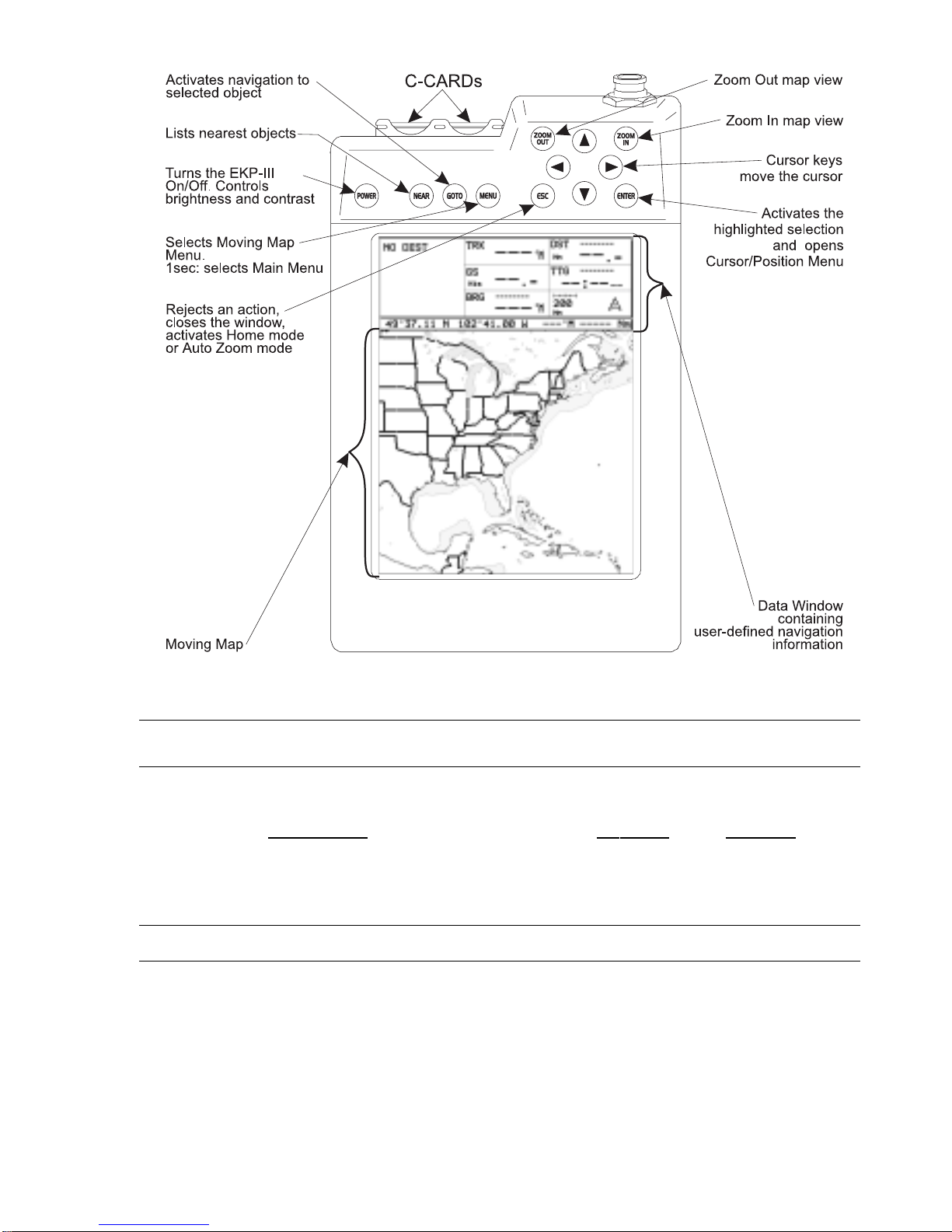
Fig. 1.2 - The EKP-III
1.3 FLYING START
These pages provide a very brief overview of several of the EKP-III’s impor tant features, the
Main Menu, the Mo
ving Map, GoTo flights and locating a Waypoint in the Database. It does
not replace the User Manual, which should be read to get the fullest possible use from your
EKP-III.
NOTE
The EKP-III is an aid to navigation. It does not replace paper charts and good judgement.
1.3.1 THE MOVING MAP
Before starting, connect the EKP-III to power and place the antenna with a clear view of the
sky. Insert a C-MAP NT+C-CARD (label facing front) into either slot at the top of the EKPIII. Press ‘POWER’ to start the EKP-III. The EKP-III will identify the coverage of the
EKP III USER MANUAL 13
Page 14
14 EKP III USER MANUAL
C-MAP NT+ C-CARD (if one is installed), its date of production, software name and version,
library version followed by the Warning page. Press ‘ENTER’ to exit from the War ning page
and enter the Mo
ving Map mode. T he Mo
ving Map is the default state displaying the Moving
Map screen and the Data Window. The Data Window contains navigation information boxes.
(See Chapter 3 for details on Mo
ving Map mode).
To Change the Scale of the Moving Map
Use ‘ZOOM IN’ and ‘ZOOM OUT’ to change the map display scale.
To Select Position
Use the cursor keys to scroll to the location you want.
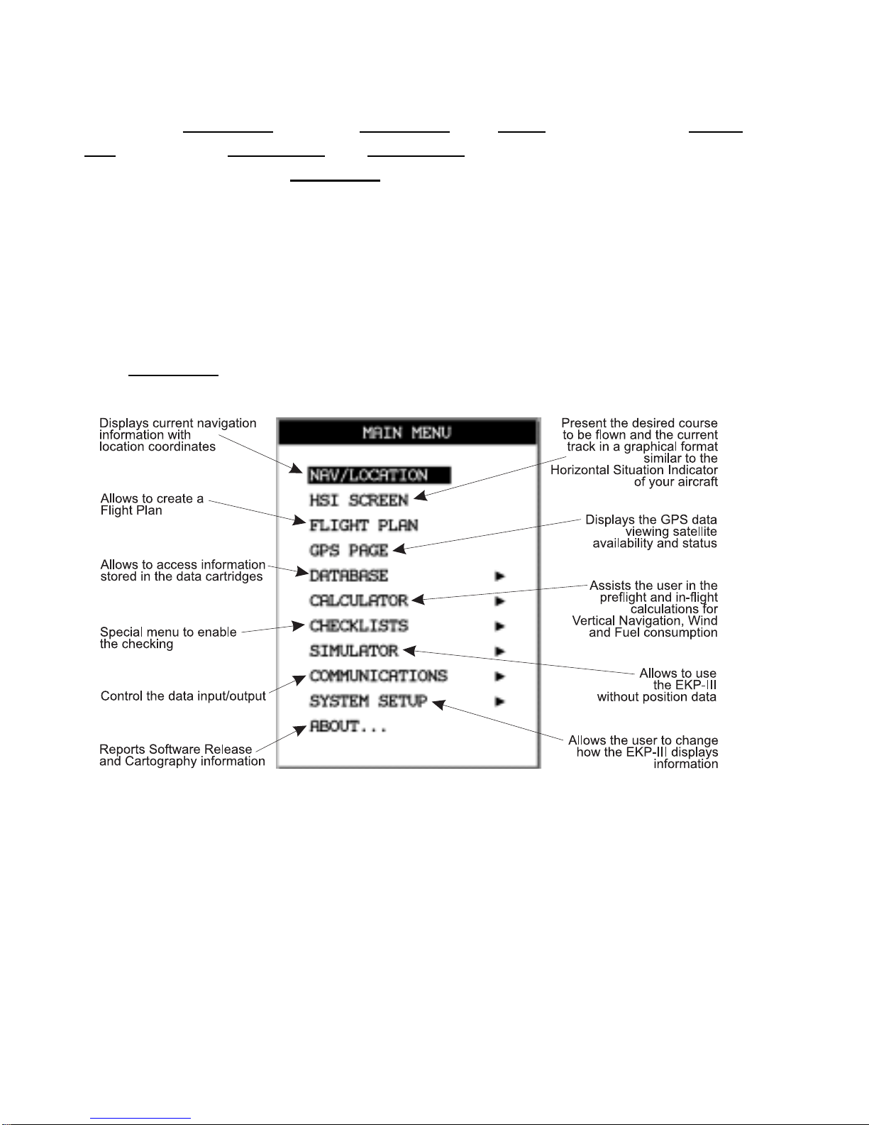
1.3.2 THE MAIN MENU
From Moving Map
press ‘MENU’ for 1 second to display the Main Menu:
Fig. 1.3.2 - Main Menu
1.3.3 MOVING MAP FUNCTIONS
The Moving Map operates in Auto Home, Auto Zoom, and Cursor Mode. The screen will
behave differently based on the mode of operation selected.
The Auto Home mode will allow the user to pan away from his present position to view
other parts of the map, and return to present position automatically when no buttons are
pushed for a pre-determined amount of seconds.
Page 15
Auto Zoom mode will keep your present position, and your destination in the screen at all
times. The screen will automatically zoom in as you get closer. To shut off this function, simply select OFF.
The Cursor Mode (OFF Selected) will allow you to move the map to any position to
view data or details. To return to your present position, just press ESC (escape key) while in
moving map.
The control for these functions is found in the Moving Map Menu, under Auto
Position Mode.
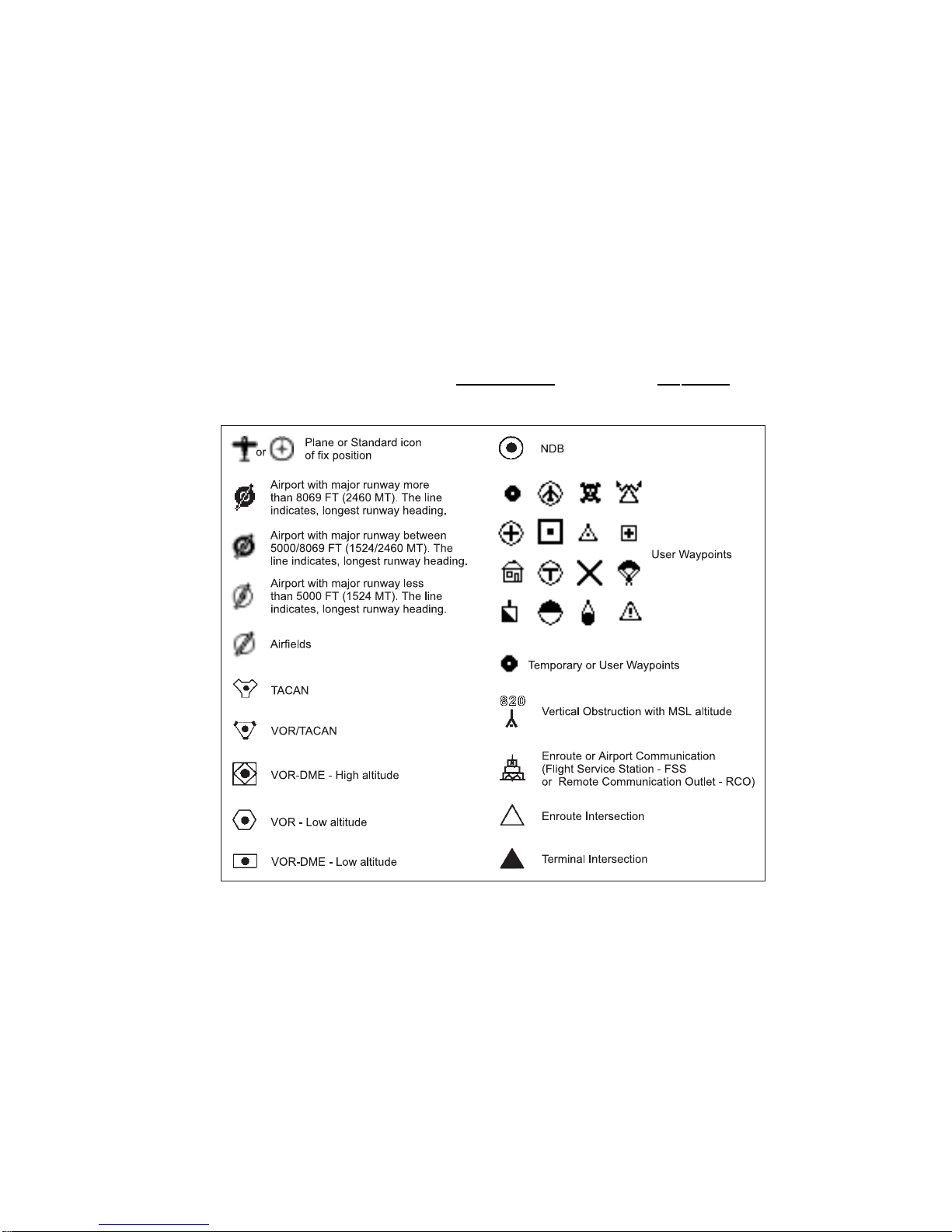
1.3.4 MOVING MAP ICONS
The following icons are displayed on the Moving Map to represent Waypoints, navigation aids
and airports.
Fig. 1.3.4 - Moving Map Icons
1.3.5 COURSE PREDICTOR
Indicates the projected position at the set time interval if the cur rent speed and heading are
kept. This allows the pilot to correct for wind drift, in real time, right from the moving map.
To select course predictor:
'MENU' 1 sec. + "SYSTEM SETUP" + 'ENTER' + "FIX SETUP" + 'ENTER' +
"COURSE PREDICTOR" + 'ENTER'
EKP III USER MANUAL 15
Page 16

16 EKP III USER MANUAL
1.3.6 GOTO
GoTo sets a 1-leg course from the present position to any location or selected Waypoint.
To activate a GoT
o Flight Plan move the cursor to the desired location or Waypoint
and press ‘GOTO’. T he GoTo menu box will open enabling you to activate the current cursor
position or search the Da
tabase for a specific object to fly to. To activate the current cursor
position, highlight “CURSOR” and press ‘ENTER’.
To activate a GoTo F
light Plan to a specific Database item, select the category and
press ‘ENTER’. Select the database item and press ‘GOTO’ ag ain to activate.
To deactivate, press ‘GOTO’ and select “DEACTIVATE”.
1.3.7 DATABA SE
The Database function allows the user to access infor mation stored in the data cartridges on
Airports, VOR’s, NDB
’s, Intersections and User Waypoints. Searching the Database allows the
user to activate GoTo F
light Plans and locate the item on the map.
There are two methods of accessing the Da
tabase information. The first is through the
Da
tabase
function within the Main Menu and the second is directly from the Moving Map dis-
play (see Chapter 5).
Page 17

2
The Basics
This chapter provides general information about the functions of the keys, inserting and
removing data cartridges and entering data (connecting the EKP-III to power and using the
antenna are described in Chapter 15).
2.1 THE KEYBOARD
The EKP-III has 12 keys, which access and control features. Some keys perform different tasks
based on the operation mode. A quick key guide is displayed at the bottom of many menus for
easy reference.
Below we indicate the keys in capital letters enclosed between single inverted commas,
for example ‘MENU’. When a key, for example ‘MENU’, must be pressed and held down for
more than 1 second it is shown as ‘MENU’ 1 sec.
The Power key
‘POWER’: press and hold to tur n the EKP-III On.
‘POWER’ 3 sec.: once the EKP-III has been turned On tur ns the EKP-III Off.
‘POWER’: (immediately release!) once the EKP-III has been tur ned On displays the
Brightness and the Contrast Menu.
The Menu key
‘MENU’: selects the Mo
ving Map Menu.
‘MENU’ 1 sec.: opens Main Menu (equivalent to press ‘MENU’ twice).
The GoTo key
Activates a F
light Plan to the cursor position (in Moving Map) or to selected object (in
other modes).
EKP III USER MANUAL 17
Page 18

The Near key
Displays a list of the 20 nearest objects relative to fix position
or cursor position if
no fix is available.
The Esc key
Rejects an action, closes a window or activates Home
or Auto Zoom mode.
The Enter key
Selects the desired option or confirms selection. Also opens the Cursor/P
osition Menu.
The ar row ,-up, -left, -right, -down cursor keys
Moves the cursor on the moving map Moving Map, quickly and accurately. Also
scrolls to the desired options in menu page(s).
The Zoom-In key
Shows more detail of a smaller area by changing the chart scale and zooming in on
the map display.
The Zoom-Out key
Shows less detail of a larger area by changing the chart scale and zooming out on
the map display.
2.2 TURNING THE EKP-III ON AND OFF
Before powering On the EKP-III, check for the correct voltage (10-35 Volt DC) and the correct connections. (See Typical Connections, Par. 14.5.)
2.2.1 TURNING ON
Press and hold ‘POWER’ for 1 second. The EKP-III emits one rapid beep sound and a Title
page containing information about the Product name, Software version, library version and cartridges installed is displayed. This data can also be viewed in the "About" page in the "Main
Menu".
18 EKP III USER MANUAL
Page 19
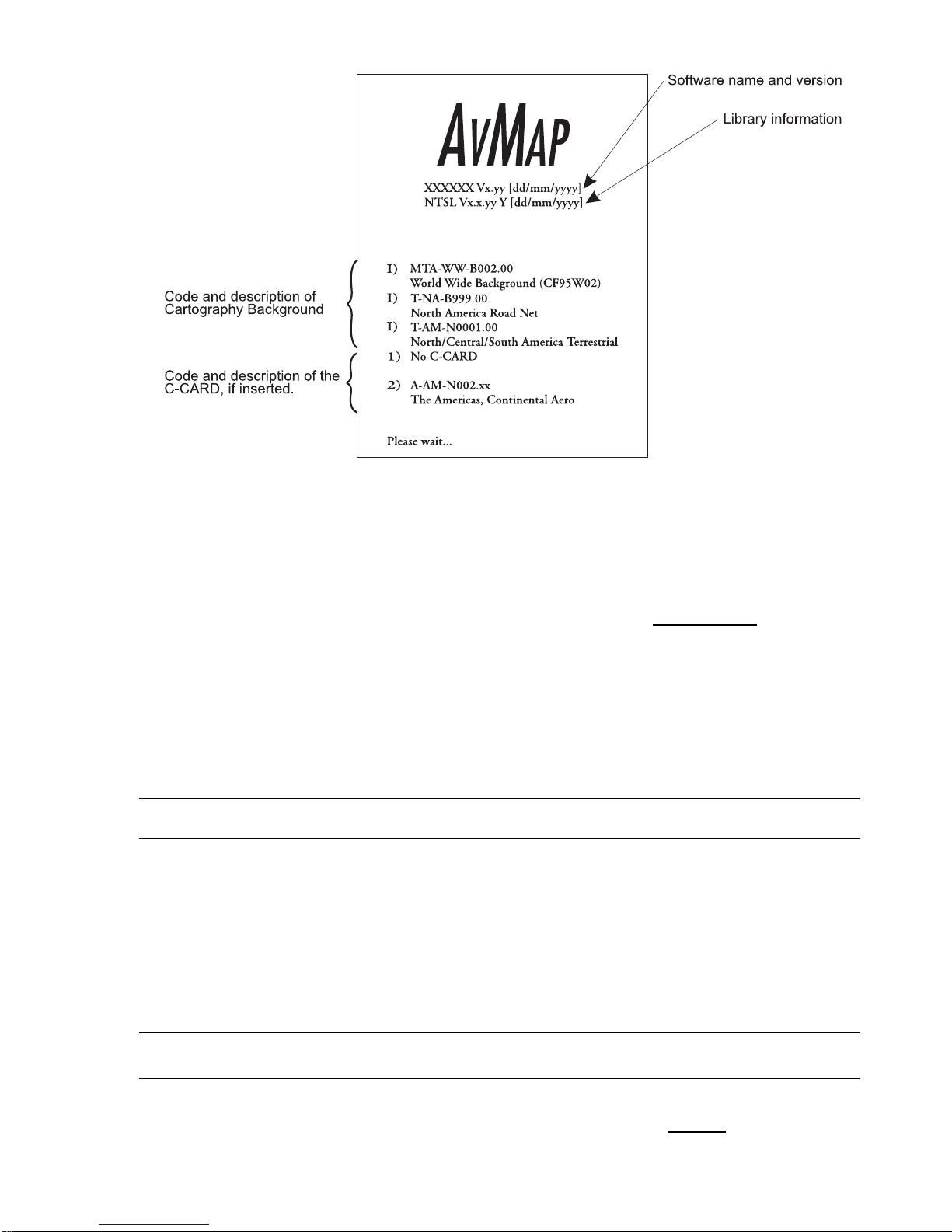
Fig. 2.2.1 - Title page
After a few seconds the Warning page is displayed, reminding you that the EKP-III is an aid to
navigation and should be used with appropriate prudence. The electronic charts are not intended to substitute for the official charts. Press ‘ENTER’ to open the Mo
ving Map screen.
2.2.2 TURNING OFF
‘POWER’ 3 sec.: a countdown timer appears on the screen, if you release the key before the
countdown timer reaches zero, the EKP-III will remain On.
2.3 CHANGING BRIGHTNESS & CONTRA ST
Press and immediately release ‘POWER’ to adjust the brightness and the contrast of the display
and keyboard (do not press and hold the key or the “power-off” message will be displayed!).
To increase/decrease the brightness use respectively up/down cursor k eys . Similarly, to
increase/decrease the contrast use left/right cursor keys.
Use ‘NEAR’ to choose Night Palette and ‘MENU’ to choose Normal palette.
2.4 SELECTING THE LANGUAGE
It is possible to select the language in which the information is displayed (for screen labels,
menus and options, but it does not affect the map information). T he def
ault setting is English.
EKP III USER MANUAL 19
Page 20
20 EKP III USER MANUAL
>‘MENU’ 1 sec. + “SYSTEM SETUP” + ‘ENTER’ + “GENERAL SETUP” + ‘ENTER’ + “LANGUAGE” + ‘ENTER’ Choose the languag e you want and press ‘ENTER’ again to confirm.
2.5 EXTERNAL CONNECTIONS
2.5.1 INTERNAL/EXTERNAL GPS SOURCE
The EKP-III has an internal GPS Receiver. Be sure the Fix Source is set to Internal GPS to
receive data from this internal receiver.
>‘MENU’ 1 sec. + “SYSTEM SETUP” + ‘ENTER’ + “FIX SETUP” + ‘ENTER’ + “FIX
SOURCE” + ‘ENTER’ Choose Inter nal GPS and press ‘ENTER’ to confirm.
Otherwise if the EKP-III is using an external NMEA0183
positioning source, set the
Fix Source as External NMEA0183.
The recognized Input NMEA0183 messages are the following: GGA, GLL, GSA, GSV, HDG, HDM, HDT, PCMPA, RMC, VHW, VTG (see
Appendix F for more details on NMEA
sentences).
>‘MENU’ 1 sec. + “SYSTEM SETUP” + ‘ENTER’ + “FIX SETUP” + ‘ENTER’ + “FIX
SOURCE” + ‘ENTER’
Choose External NMEA0183
and press ‘ENTER’ to confirm.
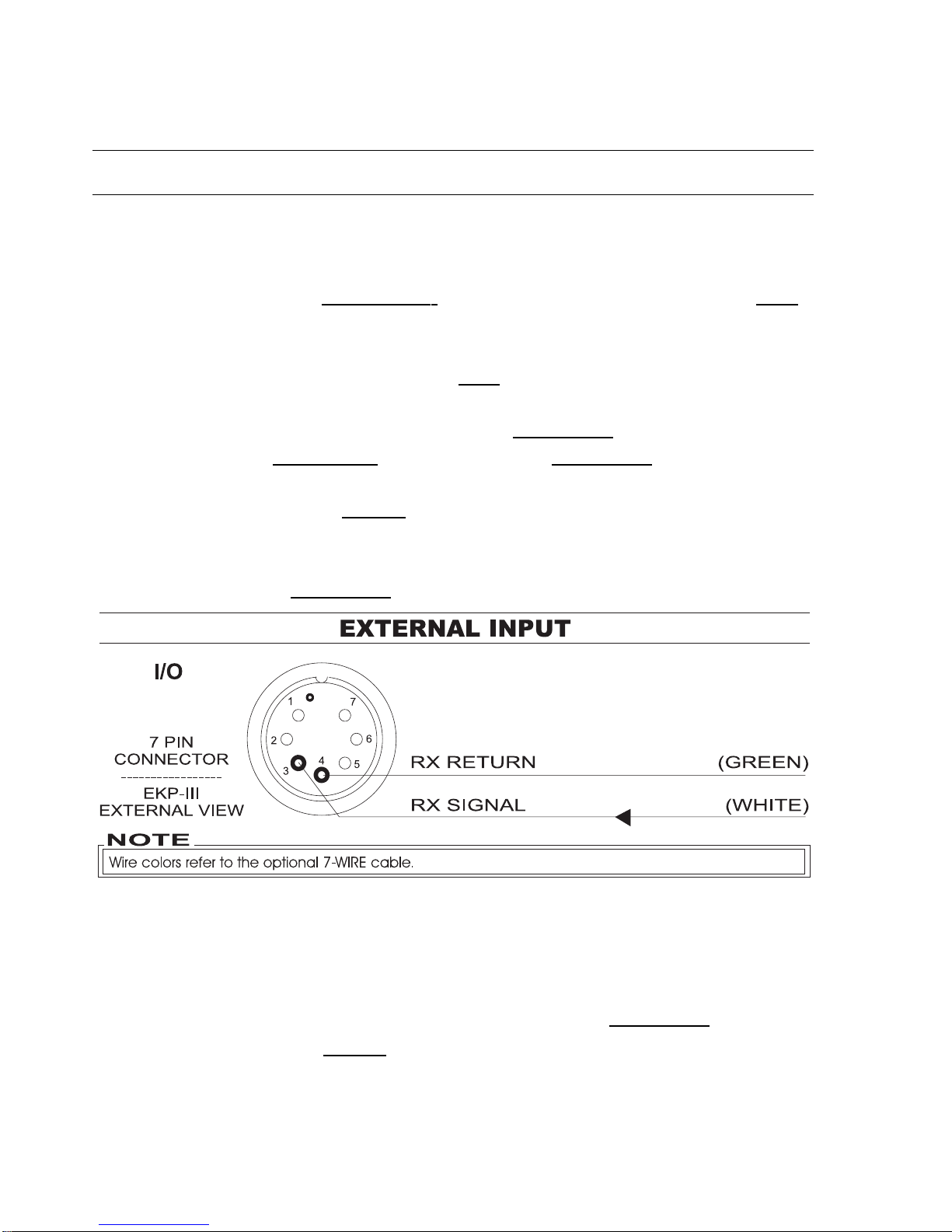
Fig. 2.5.1 - External Input
2.5.2 NMEA OUTPUTS
The EKP-III can be connected to external equipment that acce pts NMEA0183 data input.
Once attached, the output of NMEA
formatted position information can be enabled in the
following manner:
>‘MENU’ 1 sec. + “COMMUNICATIONS” + ‘ENTER’ + “NMEA OUTPUT” + ‘ENTER’
Page 21
The def
ault setting is Off. The Output NMEA0183
messages are the following: APA,
APB, BOD, BWC, GGA, GLL, HSC, RMA, RMB, RMC, VTG, WCV, XTE (see Appendix F
for more details on NMEA
sentences) BOD, BWC, GGA, GLL, HSC, RMA, RMB, RMC,
VTG, WCV, XTE (see Appendix F for more details on NMEA
sentences).
Fig. 2.5.2 - NMEA Connections
2.5.3 DIFFERENTIAL INPUT
The EKP-III can be connected to a DGPS
Beacon Receiver that sends R
TCM-104 data. To
select the Differential Correction you want among NONE, W
AAS, RTCM 1200,RTCM 2400,
RTCM 4800, RTCM 9600, RTCM 19200, RTCM 38400 follow the procedure:
‘MENU’ 1 sec. + “SYSTEM SETUP” + ‘ENTER’ + “FIX SETUP” + ‘ENTER’ + “DIFFERENTIAL CORRECTION SOURCE” + ‘ENTER’
The default setting is WAAS which works off the inter nal GPS receiver.
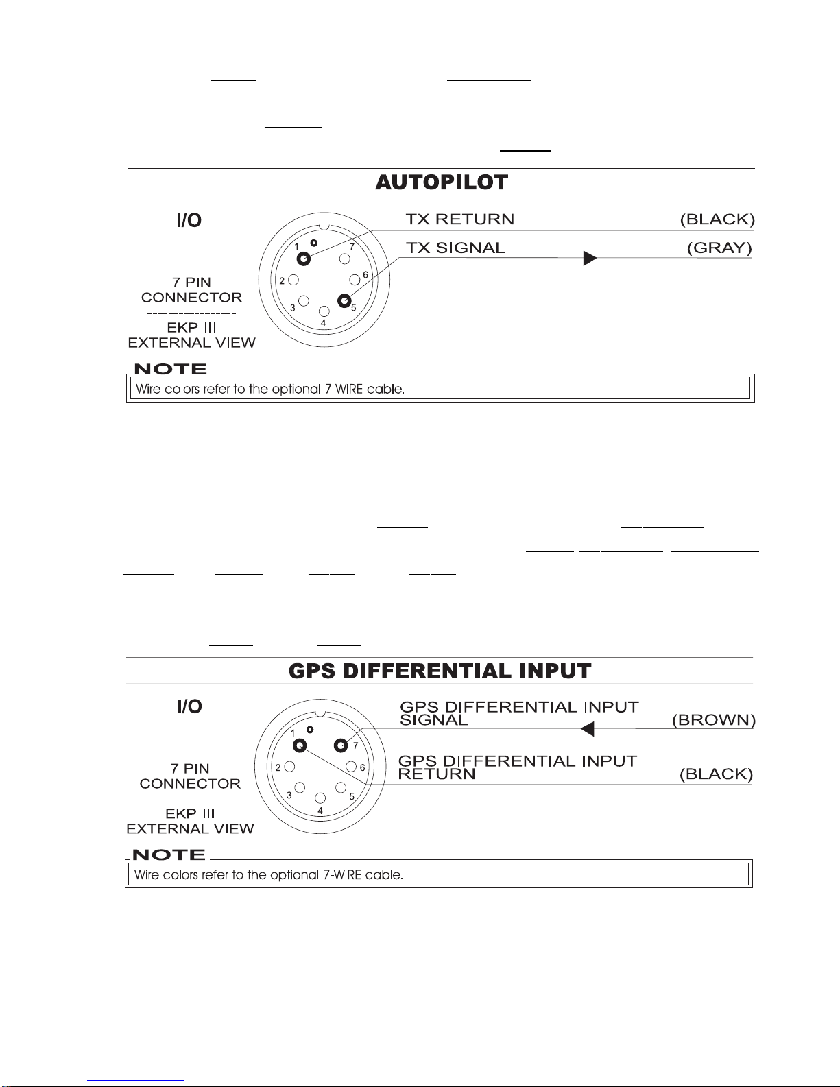
Fig. 2.5.3 - Differential input connections
EKP III USER MANUAL 21
Page 22
22 EKP III USER MANUAL
2.5.4 DOWN OR UP-LOAD FLIGHT PLANS & TRACKS
The EKP-III can also send and receive Flight Plans from the C-MAP PC-PLANNER NT
+
software program or another device compatible with it. This requires an optional power/data
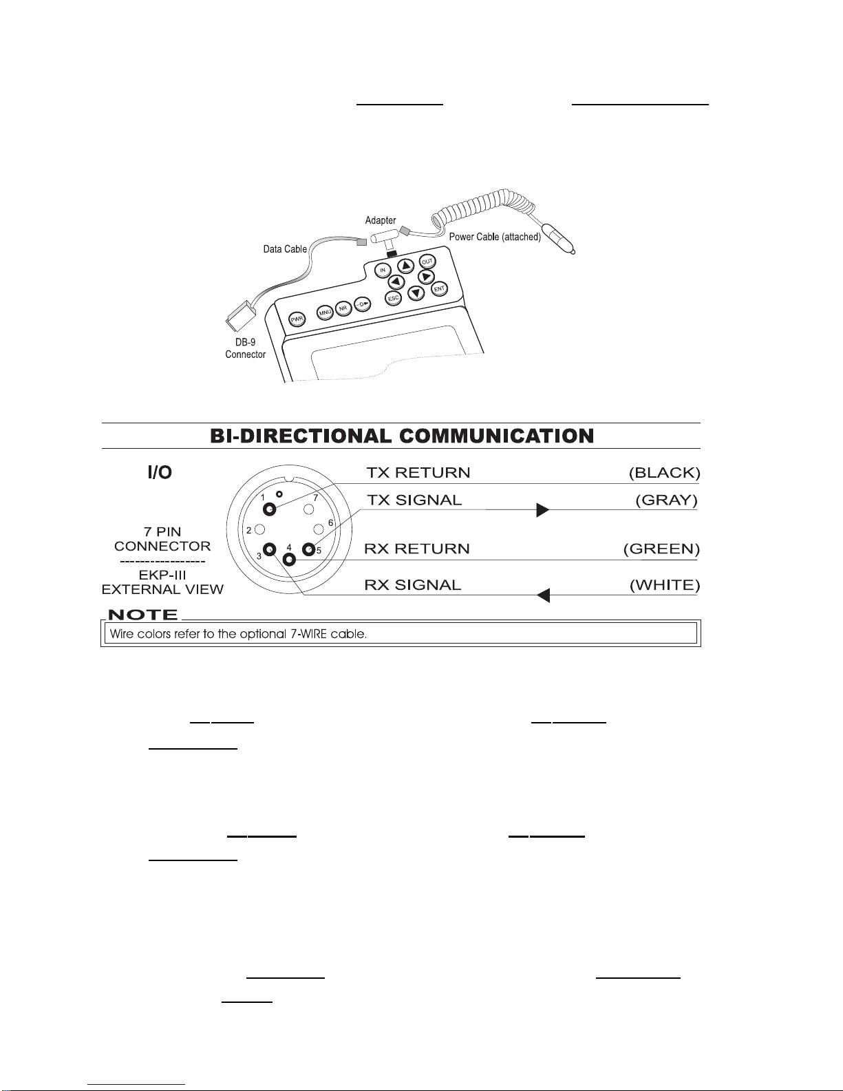
cable that can be purchased from your avionics dealer or C-MAP (see Fig. 2.5.4) for a proper
connection to the device (see Fig. 2.5.4a).
Fig. 2.5.4 - Optional Power/Data cable
Fig. 2.5.4a - Bi-directional Communicatons
2.5.4.1 Download/Upload Waypoints
The Download Waypoint function allows you to send the current Waypoints to the serial port
using the NMEA0183
$WPL sentence (see Appendix F):
>‘MENU’ 1 sec. + “COMMUNICATIONS” + ‘ENTER’ + “WAYPOINTS DOWNLOAD” +
‘ENTER’
The Upload Waypoint function allows you to receive Waypoints from the serial por t
using the NMEA0183
$WPL sentence (see Appendix F):
>‘MENU’ 1 sec. + “COMMUNICATIONS” + ‘ENTER’ + “WAYPOINTS UPLOAD” +
‘ENTER’
2.5.4.2 Download/Upload Flight Plan
The Download F
light Plan function allows you to send the current Flight Plans to the
serial port using the NMEA
0183 $WPL and $RTE sentences (see Appendix F):
Page 23

EKP III USER MANUAL 23
>‘MENU’ 1 sec. + “COMMUNICATIONS” + ‘ENTER’ + “FLIGHT PLAN DOWNLOAD”
+ ‘ENTER’
The Upload Flight Plan function allows you to receiv e F
light Plans from the serial port
using the NMEA
0183 $WPL and $RTE sentences (see Appendix F):
>‘MENU’ 1 sec. + “COMMUNICATIONS” + ‘ENTER’ + “FLIGHT PLAN UPLOAD” +
‘ENTER’
The received Flight Plan is saved in the cur rent Flight Plan. If the cur rent Flight Plan
contains data the user should be asked to confirm the action (overwriting the existing F
light
Plan) or choose another Flight Plan.
2.5.4.3 Download Track
The Download T rack function allows you to send Track data from the serial port using
the C-MAP Proprietary NMEA0183
$PCMPT sentence (see Appendix F):
‘MENU’ 1 sec. + “COMMUNICATIONS” + ‘ENTER’ + “TRACK DOWNLOAD” +
‘ENTER’
2.6 ADDITIONAL C-CARDS
The EKP-III uses two types of C-MAP cartridges: either a chart cartridge or a data storage cartridge.
A chart cartridge, called C-CARD, contains detailed data of the area covered. The
Aviation Database Cartridge ( C-CARD) displays public and military air ports with runway
layouts, airspace boundaries, VORs, NDBs
and Intersections.
A data storage cartridge, called User C-CARD
(see Par .5.4), can be used to permanent-
ly store your F
light Plans, Waypoints and Track, for later upload into the EKP-III. This data
can also be shared with other AvMap plotters compatible with this feature.
2.6.1 INSERTING C-CARD
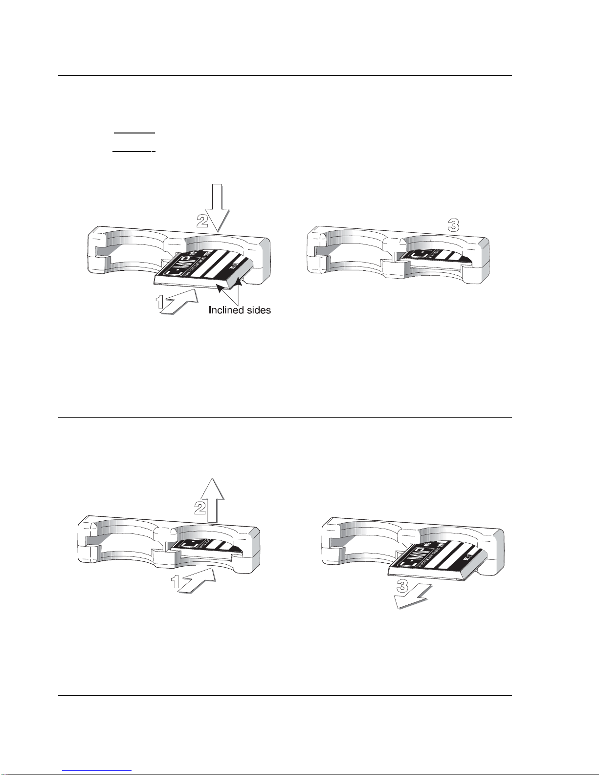
Hold the C-CARD by the short inclined side so that you can see the C-MAP label.
Fig. 2.6.1 - Inserting C-CARD (I)
The EKP-III has two C-CARD slots on top of the EKP-III. It does not matter which
slot is used. Insert the C-CARD in one of the slots on top of the EKP-III, above ‘POWER’.
Page 24
NOTE
C-CARD should be inserted or removed when the EKP-III is powered Of f . Be sur e to keep the slot fr ee
of moistur e; it is NOT waterproof.
While holding the EKP-III facing towards you, hold the C-CARD with the gold contacts
toward the r
eceiver and “C-MAP” facing up. Insert the C-CARD into one of the slots at the
top of the r
eceiver. Push the C-CARD all the way in. When it will go in no further, press the
edge of the C-CARD down gently until it rests in place behind the plastic catch.
Fig. 2.6.1a - Inserting C-CARD (II)
2.6.2 REMOVING C-CARD
To remove the C-CARD, turn your EKP-III off and push the C-CARD in and up gently to
free it from the plastic catch, then slide it out. The C-CARD will pop out easily.
Fig. 2.6.2 - Removing C-CARD
NOTE
Data cartridges are available from your dealer or dir ectly fr om C-MAP (see addr ess on the r ear cover).
24 EKP III USER MANUAL
Page 25

2.7 SYSTEM SETUP OPTIONS
You may select how the EKP-III displays primary infor mation (such as how time is displayed)
from the System Setup Menu.
>‘MENU’ 1 sec. + “SYSTEM SETUP” + ‘ENTER’
Refer to Chapter 13 for information about the System Setup Menu.
2.8 DATA ENTRY
Information is keyed into the EKP-III when editing a Waypoint, entering a Flight Plan, using
the calculator and searching the Da
tabase. When the field is highlighted:
- Enter or edit data by pressing up/down cursor keys to step through the available
characters until the desired character is displayed.
- Press right cursor key to move the cursor to the right.
- Use left cursor key to move the cursor to the left.
Some pilot-entered data requires either a +, - or a hemisphere identification:
- Move the cursor over the displayed symbol and press up/down cursor key until the
desired symbol appears.
- Press ‘ENTER’ to continue to the next line or to return to the previous menu.
EKP III USER MANUAL 25
Page 26

26 EKP III USER MANUAL
A
Page 27

3
The Moving Maps
The Moving Map is the default state of the software. This mode displays the Moving Map
screen and Data Window. The Moving Map displays map detail in Home,Auto Zoom or
Cur
sor mode. The operation mode will determine the options available within the screen. The
Da
ta Window contains the navigation infor mation pertaining to the active flight; these fields
can be customized.
From the Mo
ving Map
screen you can obtain Automatic Info and Full Info for
Da
tabase
objects. Here you can also open the Cursor/Position Menu for features related to
F
light Plans,Waypoints and airspace.
3.1 OPERATING MODES
3.1.1 CURSOR MODE
In Cur
sor mode the screen is controlled by your movement of the cursor. When in Cursor
mode, a data field line will appear under the Data Window providing LAT/LON of the cursor
position. If a fix has been computed, a distance and bearing
will also appear from the position
fix to the cursor.
When in Cur
sor mode it is possible to scroll on the map such that the position fix will
not be displayed on the screen. When this occurs, you can quickly display y our position
by acti-
vating Home
mode (press ‘ESC’ once). At this time, the system will operate in Home mode (see
below Par. 3.1.2).
If you have a position fix, and would like to continue with the cursor at the last position, press ‘ESC’ again (if the cursor keys have not been pressed between these two ‘ESC’
presses, the cursor will revert to the original position).
To activate the cursor from the current fix position
, simply press the cursor keys and
the Cur
sor mode becomes active at the present fix position.
The cursor can be used to create and edit W
aypoints and Flight Plans; identify airspace,
obtain info about objects, project radial lines and measure distance (see Cursor Menu, Par. 3.6).
EKP III USER MANUAL 27
Page 28

3.1.2 HOME (SCREEN AMPLIFIER) MODE
The Home mode (also called Screen Amplifier) is used to keep the fix position within the visible map. The map is scrolled and redrawn automatically as your position
moves. When this
mode is active the cursor is hidden. When in Home
mode, there will be no position line dis-
played at the bottom of the Da
ta Window.
NOTE
Auto Zoom must be selected to Off in the Moving Map Menu.
A slow flashing airplane icon will indicate your current position. The air plane will be pointing
in the direction of movement. Home mode can display the map in North-up, Course-up or
Track-up (see Moving Map Settings, Par. 3.5).
To deactivate Home
mode press ‘ESC’ activating the cursor at the previous position or
press a cursor key to enable the cursor under the current fix position
.
3.1.3 AUTO ZOOM MODE
The A
uto Zoom mode is used to keep the fix position
and destination (Target) visible on the
map. The map is scrolled and zoomed automatically to keep the best view possible. When this
mode is active the cursor is hidden. When in A
uto Zoom mode, there will be no position line
displayed at the bottom of the Da
ta Window.
NOTE
Auto Zoom must be selected to On in the Moving Map Menu.
To activate Auto Zoom mode press ‘ESC’ in Moving Map.Auto Zoom requires a
position fix and an active destination point. If a destination point is not present it works as
Home
mode.
To deactivate A
uto Zoom mode press ‘ESC’ to enable the cursor at the previous position or press a cursor key to enable the cursor under the current fix position. Instead if you
press ‘ZOOM IN’ or ‘ZOOM OUT’ enables the cursor under the current fix position
and
zooms on the map.
3.2 DATA WINDOW
28 EKP III USER MANUAL
Page 29

The Mo
ving Map screen provides the option for a Da
ta Window display for a user defined nav-
igation information panel. This window is fixed at the top of the screen. During Cur
sor mode,
an additional line is displayed at the bottom of this box with details on the cursor position. See
Par. 3.5.3 and 3.5.4 for details on customizing the data fields display.
The data fields window is updated continuously during flight. For full information
regarding navigation and GPS
data, you can select the Nav/Location screen from the Main
Menu (see Chapter 4).
To view A-B BRG and DST, the “Info: A-B Function” must be selected for display in
a Data window field.
3.3 AUTOMATIC INFO
Automatic Info will provide details on cartog raphic objects, Waypoints and navaid items when
the cursor is placed over them. This is a user setting that can be defined in Mo
ving Map Menu.
The def
ault is Automatic Information to be displayed for aeronautical and terrestrial data.
When the Cur
sor mode is active, the Automatic Info window appears on the Moving
Map screen if there is an object under the cursor position. Depending on the cursor position
the window is opened in the top or bottom of the screen.
If additional infor mation is available for the object, the box will indicate with the following message: “Press and hold ENTER to select”. By doing so, you will activate the information box and can then select the item using the cursor keys (if more than one item is displayed). With the item highlighted, press ‘ENTER’ again and the additional details will be displayed. If the information is an airpor t, the ‘ENTER’ key will toggle between the pages of
data. Press ‘ESC’ to exit.
3.4 CURSOR OR POSITION MODE
The Moving Map page provides a sub-menu directly related to the cursor or position fix.
To activate from the Mo
ving Map press ‘ENTER’. The menu displayed will be Cursor or
P
osition de pendent upon the map mode (see map mode above). The two menus are dis-
played on the next page:
EKP III USER MANUAL 29
Page 30
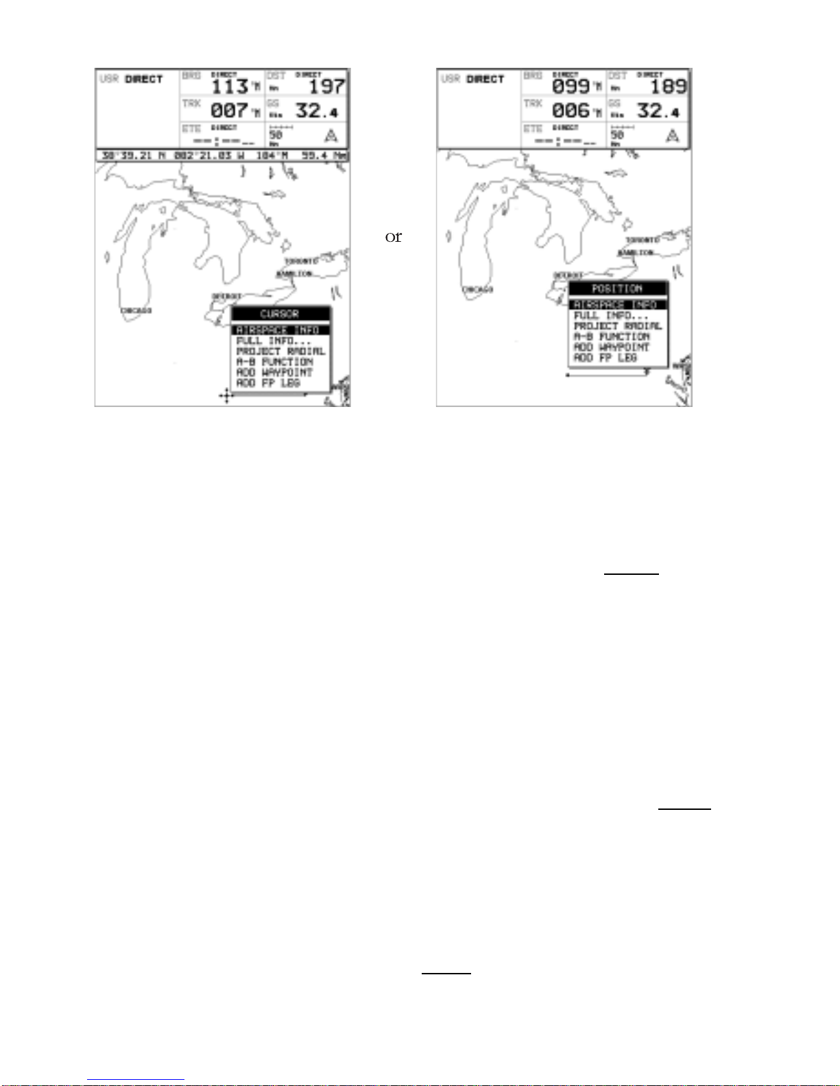
Fig. 3.4 - Cursor/Position Menu
3.4.1 AIRSPACE INFORMATION
Airspace Info will display infor mation about the airspace within the cursor/position fix. The
selected area(s) of airspace queried is highlighted.
>‘ENTER’ + “AIRSPACE INFO” + ‘ENTER’
Like Automatic Info the window is opened in the top or bottom part of the screen.
One window displays all airspace objects. Displayed information is the following: Name of airspace; type of airspace; altitude rang e; tower frequency for airpor t traffic areas or main air por t
frequency for Class B and Class C areas.
3.4.2 FULL INFORMATION
Full Info window displays C-Map attribute information for the object under the cursor/position.
>‘ENTER’ + “FULL INFO” + ‘ENTER’
Found objects are presented using a tree structure. Using the cursor keys highlight the
object desired and press ‘ENTER’ for further details.
3.4.3 PROJECT RADIAL
The project radial feature creates a line at a given bearing and distance from a navaid or user
waypoint. If no object is present, an error message stating “Object not found” will appear on
30 EKP III USER MANUAL
Page 31

the screen. The EKP-III will store 10 radials.
To project a radial, first select the object with the cursor, then:
>‘ENTER’ + “PROJECT RADIAL” + ‘ENTER’
Using the cursor keys enter the Bearing and press ‘ENTER’. The Distance box is now
active; using the cursor keys enter the Distance for the line to extend and press ‘ENTER’.
To remove a radial, select the object icon or the radial line with the cursor, then:
>‘ENTER’ + “PROJECT RADIAL” + ‘ENTER’
A Warning message appears asking if you would like to remove the radial. Press
‘ENTER’ to confirm or ‘ESC’ to exit.
To remove all radials stored in the EKP-III (see also Par. 14.9):
>‘MENU’ 1 sec. + “SY STEM SETUP” + ‘ENTER’ + “CLEAR ALL RADIALS” + ‘ENTER’
3.4.4 A > B FUNCTION
The A-B Function allows you to calculate distance and bearing between two specified points
(“A” and “B”). The distance and bearing
will appear in the A-B data field box at the top of the
screen. (This must be selected for display; see Da
ta Window, Par. 3.2).
To measure two points:
>Place the cursor at first position “A” + ‘ENTER’ + “A-B FUNCTION” + ‘ENTER’
>Place the cursor at second position “B” + ‘ENTER’ + “A-B FUNCTION” + ‘ENTER’
You can also measure distance from the current fix position using the A-B feature.
From Home
or Auto Zoom mode:
>‘ENTER’ + “A-B FUNCTION” + ‘ENTER’
This will place “A” at the current fix position, then:
>Place the cursor at second position “B” + ‘ENTER’ + “A-B FUNCTION” + ‘ENTER’
This line will remain on the screen until it is deactivated. To deactivate:
>‘ENTER’ + “A-B FUNCTION” + ‘ENTER’
3.4.5 WAYPOINT HANDLING
Associate Waypoint with User Waypoint Alarm (13.3.2a):
When editing the waypoint, select the icon for the waypoint. Any Waypoint with this icon
wil activate a user Waypoint Ar rival Alar m if this feature is turned on in the System Setup Alarm Setup Menu.
The EKP-III provides storage for 1000 W
aypoints. These can be a combination of
User Waypoints or Flight Plan Waypoint storage.
User W
aypoints can be edited, searched and used as Waypoints within a Flight Plan.
User W
aypoints can be created from the Moving Map screen or via the Database page (see
Da
tabase, Chapter 8 for entering Waypoints from the Database).
EKP III USER MANUAL 31
Page 32

Add Waypoint:
>Place the cursor at position + ‘ENTER’ + “ADD WAYPOINT” + ‘ENTER’
Edit Waypoint:
>Place the cursor over Waypoint + ‘ENTER’ + “EDIT WAYPOINT” + ‘ENTER’
The Edit Waypoint box will appear. Using the cursor keys scroll through the alphanumerics to create an eight character name, adjust the La
titude or Longitude or select an icon.
Press ‘ENTER’ within each character field to mov e to the next field. After completing the icon
selection, the box will close and the new data is stored.
Remove Waypoint (present only if there is a W
aypoint under the cursor position):
>Place the cursor over Waypoint + ‘ENTER’ + “REMOVE WAYPOINT” + ‘ENTER’
A shadow of the icon will remain on the screen until the map is redrawn.
3.4.6 FLIGHTPLAN
The EKP-III provides storage for 10 Flight Plans of 100 legs each. From the Moving Map
screen you can edit and create F
light Plans using the cursor. The F
light Plan edited or created
will be the one that is currently viewed by the software (see Chapter 6).
Creating a Flight Plan
To create a new F
light Plan from the Moving Map screen, be sure the current viewed
F
light Plan (see Chapter 6) is empty. Place the cursor at the desired position on the map, this
can be an aero object (APT, VOR, NDB
, INT), User Waypoint or a spot on the map.
>‘ENTER’ + “ADD FP LEG” + ‘ENTER’
This will create the first Waypoint within your Flight Plan. Continue this way to add
the remaining W
aypoints within your Flight Plan.
NOTE
If several aer o objects are found under the cursor, the system will default the selection as follows: Airport, VOR,
NDB, INT. If no aer o object is found, a temporary Waypoint is placed at the coordinates of the cursor and is
named “WPTxxx” (where xxx is a number).
Add Waypoint
To add a W
aypoint (leg) to the viewed (current) Flight Plan place the cursor over the position.
>‘ENTER’ + “ADD FP LEG” + ‘ENTER’
This will place another leg onto the end of the cur rent viewed Flight Plan.
Remove Waypoint (present only if there is a W
aypoint under the cursor position):
>Place the cursor over existing Waypoint + ‘ENTER’ + “REMOVE WAYPOINT” + ‘ENTER’
If the W aypoint was within the Flight Plan, the revised leg will be drawn on the screen.
Inserting a Waypoint
32 EKP III USER MANUAL
Page 33

To edit a flight plan on the moving map, be sure the flight plan is selected as the
“Viewed” f light plan. (See Sec. 6.1.1). To insert a waypoint between two existing waypoints in
the viewed flight plan, move the cursor over the leg to be edited:
‘ENTER’ + “ADD FP LEG” + ‘ENTER’.
The new waypoint is now inserted into the flight plan.
3.5 MOVING MAP MENU
The Moving Map Menu provides access to the set up functions of the Moving Map display.
Here you can define the items for display, Map Orientation, Auto Zoom, selective display and
other settings to customize the EKP-III for your navigational needs.
From Mo
ving Map press ‘MENU’ to display the Moving Map Menu. From here use
the cursor keys to select the item desired and press ‘ENTER’ to activate. At any time, press
‘ESC’ to back out of the menus and return to the Mo
ving Map.
Fig. 3.5 - Moving Map Menu
3.5.1 VIEWED FP
This item enables you to select the Flight Plan to display on the Moving Map from the list of
stored Flight Plans. The f light Plan that is “Viewed” can then be edited or activated from the
Moving Map display.
‘ >MENU’ + “VIEWED FP” + ‘ENTER’
EKP III USER MANUAL 33
Page 34

The Flight Plan list will display, using the arrow keys, highlight the flight plan and press
‘ENTER’. Select an EMPTY flight plan if you do not want a flight plan to display on the
Moving Map, or to create a new Flight Plan from the Moving Map.
3.5.1.1 AUTO POSITION MODE
To set Auto Zoom or Auto Home mode:
‘MENU’ + “AUTO POSITION MODE” + ‘ENTER’
The following options are available”
OFF - The moving map display will remain in ‘CURSOR’ or ‘HOME’ mode as set
by the user.
AUTO ZOOM - Used to keep the current position and the destination (Target) visi-
ble on the map. T he map is scrolled and zoomed automatically to keep the best view possible
during all phases of flight. When A
uto Zoom is selected, and the cursor is active, the map will
reposition the cursor to the center point of the current position fix and the destination waypoint as needed to keep both items visible on the display.
AUTO HOME - The Moving Map page will automatically change to the ‘HOME’
mode when no cursor activity is present for 60 seconds. The default setting is A
UTO HOME.
A
uto Zoom is On the Auto Zoom mode is activated (see Par. 3.1.3).
'MENU' + "AUTO ZOOM" + "ON"+ 'ENTER'
The Auto Zoom mode is used to keep the fix position and the destination (T arget) vis-
ible on the map. T he map is scrolled and zoomed automatically to keep the best view possible.
3.5.2 DATA WINDOW MODE
The Da
ta Window is displayed on the top of the Moving Map. This window provides
navigation information relating to the F
light Plan and GPS data. This screen can be cus-
tomized to allow you to select the information based on your flying needs.
>‘MENU’ + “DATA WINDOW MODE” + ‘ENTER’
The following options are available for the data window display:
OFF
1-line - Provides three fields for data display.
2-lines - Provides six fields for data display.
3-lines - Provides nine fields for data display.
HSI + Fields - Provides the HSI along with 6 data fields in the top half of the
display window. (Settings for the HIS display are selected in the HIS menu pag e, see Sec.5.)
34 EKP III USER MANUAL
Page 35

EKP III USER MANUAL 35
Fig. 3.5.2 - Data Window options
3.5.3 SETUP DATA FIELDS
You can select the item to be displayed in each of the fields of the Data Window. The following
Fig . 3.5.3 displays the options available. The fields selected for each window mode option (1-line,
2-lines, etc.) are independent; therefore, you can select different fields for each window view.
Fig. 3.5.3 - Setup Data Fields
>‘MENU’ + “SETUP DATA FIELDS” + ‘ENTER’
After pressing ‘ENTER’, a box in the Data Window will be highlighted. Using the
arrow keys, select the box to be edited and press ‘ENTER’.
The OPTIONS box will appear (Fig.3.5.3) allowing you to select the item to display in
the highlighted is box. Highlight the desired item from the list and press ‘ENTER’ to accept.
You can then scroll to another box and proceed as above. Once all boxes are set up,
press ‘ESC’ to exit.
Page 36

NOTE
The Dest: Wpt Info option requires 3 ver tical fields for display; ther efor e, you can only select this option in
a top field on the 3-line display or the top field in the HIS + Fields display. If you attempt to select this item in another filed, the system will beep three times and revert to the previous selection mode.
If you have the Dest: Wpt Info displayed and would like to change to three different items, select the top of the
Destination Info box. The first filed will display the one you selected and the bottom two fields will display default items
3.5.4 DEFAULT DATAFIELDS
This will restore data fields settings to default v alues
>‘MENU’ + “DEFAULT DATA FIELDS” + ‘ENTER’
The message “DONE” will appear to the right confirming the action is complete. The
Default Fields will only be applied to the currently selected Data Window Option; i.e. 1-Line,
2-Lines, etc. .
3.5.5 MAP ORIENTATION
Map Orientation
controls the direction that the Moving Map is pointing during Home and
A
uto Zoom modes.
>‘MENU’ + “MAP ORIENTATION” + ‘ENTER’
The options are:
Track-up - will rotate the map automatically to keep your T
rack pointed toward the
top of the display (see Par. 14.2.5; System Setup + Fix Setup + Head Up Response).
Course-up - will rotate the map automatically to keep your active leg pointed toward
the top of the display.
North-up - will rotate the map automatically to keep Nor th pointing toward the top
of the display.
During Nor
th-up mode the Screen Amplifier is active. Depending on the Heading, the
fix icon is placed on one of the 8 positions. For example, if the Heading
is 45°, the fix icon is
placed on the bottom left part of the screen (see Fig. 3.5.5). This method of icon placement
allows for the maximum view ahead of the aircraft at the given direction of travel.
36 EKP III USER MANUAL
Page 37

Fig. 3.5.5 - 8 marks at the areas where the icon may appear
3.5.6 MAP PRESENTATION SETTINGS
Map Presentation allows you to select the priority of the map display and color selections
among AERO + TERRESTRIAL/AERONAUTICAL/MARINE settings.
>‘MENU’ + “MAP PRESENTATION” + ‘ENTER’
The options are: Aero + Terrest, Aeronautical, Marine. The default setting is Aero +
Ter rest. Aeronautical setting will change all land based detail to a light color to enhance the
aeronautical data. When using aviation and land based C-CARDs, be sure this setting is on Aero
+ Ter restrial. Switch to Marine when utilizing the C-MAP Marine C-CARDs.
3.5.7 AUTOMATIC INFORMATION
The display of Automatic Information is controlled by this setting. The categ or y of detail selected will be displayed on the Mo
ving Map automatically when the cursor is placed over the object.
>‘MENU’ + “AUTOMATIC INFO” + ‘ENTER’
The selection options are: OFF /AERO+TERREST /AERONAUTICAL
/TERRESTRIAL/ MARINE (refer to Par . 3.3). If the category is turned Off, no details about
objects will be displayed automatically. (Full Info is can be viewed from the Cursor Menu.) The
def
ault setting is Aero + Terrest.
3.5.8 VFR, AIRSPACE, LAND, MARINE AND OTHER SETTINGS
The following menus enable/disable the display of categ ories of data.
>‘MENU’ + “VFR/AIRSPACE/LAND/MARINE/OTHER SETTINGS” + ‘ENTER’
EKP III USER MANUAL 37
Page 38

3.5.8.1 VFR Settings
The VFR Settings category relates to the aviation features found in the Navdata C-CARD.
Airports: ON/OFF. The def
ault setting is On.
VOR: ON/OFF. The def
ault setting is On.
NDB: ON/OFF. The def
ault setting is On.
Intersections: ON/OFF. The def
ault setting is On.
Vertical Obstructions: ON/OFF. The def
ault setting is On.
Aero Objects Id: OFF/SMALL/MEDIUM/LARGE. The def
ault setting is Large.
Enroute Communications: ON/OFF. The def
ault setting is On.
3.5.8.2 Airspace Settings
The Airspace Settings categor y relates to the airspace data found in the Navdata C-CARD.
Controlled Areas: ON/OFF. The def
ault setting is On.
Restricted Areas: ON/OFF. The def
ault setting is On.
FIR and UIR: ON/OFF. The def
ault setting is Off.
MORA
: ON/OFF. The def
ault setting is Off.
3.5.8.3 Land Settings
The Land Settings menu controls the level of cartog raphic detail shown.
Roads: ON/OFF. The def
ault setting is On.
Road Labels: OFF/AMERICAN/EUROPEAN. The def
ault setting is American.
Railroads: ON/OFF. The def
ault setting is On.
City Names: ON/OFF. The def
ault setting is On.
Rivers & Lakes: ON/OFF. The def
ault setting is On.
Cultur
al Features: ON/OFF. The default setting is On.
Na
tur
al Features
: ON/OFF. The def
ault setting is On.
Landmar
ks: ON/OFF. The default setting is Off.
3.5.8.4 Marine Settings
The Marine Settings menu controls the detail shown from a C-MAP Marine C-CARD.
Lights: ON/OFF/NO SECTOR. When Lights are On lights are shown on lighthouses and
other lights that rotate, a light sector is displayed to show the range of coverage for the light.
In the No Sector setting the light is shown without sector. The def
ault setting is On.
Chart Boundaries: ON/OFF/AUTO. The def
ault setting is On.
Bathymetric & Soundings: ON/OFF. The def
ault setting is On.
Bathymetric & SND Range: Sets the min/max value for Bathymetrics and Soundings. If the
depth unit is Meter
(MT), the rang e is [0 - 15000], if Feet (FT) is [0 - 49212], if Fathom (FM)
is [0 - 8202]. The def
ault setting is [0, 33] FT.
Depth Area Limit: Sets a reference depth value (in the range [0 - 30000]): the software fills all
the bathymetric areas that have starting depth area lower than the reference v alue with grey. All
38 EKP III USER MANUAL
Page 39

other bathymetric areas are white. So, if the reference depth is 0, all areas are white, if it is
99.999 all areas are gray. The def
ault setting is 33 FT.
NOTE FOR THE EKP-III C
The Depth Areas shown on the scr een ar e filled with thr ee dif fer ent shades of blue. Selecting the Min and Max values in the range of Depth Limit, ther e ar e thr ee ar eas: [0, Min] color ed with dark blue, [Min, Max] colored in
blue and [Max, 15000] colored in light blue. The default setting is 6 Ft for Depth Areas Limit 1 and 50 Ft for
Depth Areas Limit 2.
Navigational Aids: ON/OFF. The default setting is On.
Attention
Areas: ON/OFF/CONTOUR. The default setting is Contour.
T
racks & Routes: ON/OFF. The default setting is On.
3.5.8.5 Other Settings
User Points: OFF/ICON/ICON LABEL. The default setting is Icon/Label.
Objects Overlap: ON/OFF. The def
ault setting is On. When more then one object
is at the same position, the selection of On allows the screen to
draw the objects overlapping.
LA
T/LON Grid: ON/OFF. The default setting is Off.
3.5.9 SELECTIVE DISPLAY SETTINGS
In addition to the above Moving Map Settings the Selective Display feature allows you to further
customize the display by selecting the chart scale level at which the categ ory of data will begin
displaying on the map. This feature is extremely useful in decluttering the screen in populated
areas or at times when you want to focus on a single category of data, i.e. medium airpor ts only.
>‘MENU’ + “SELECTIVE DISPLAY...” + ‘ENTER’
Scroll through the cells using the cursor keys . To select the desired scale you would like
the map to begin displaying data for the category, place the cursor within the cell and press
‘ENTER’. (T he map scale for the cell is displayed at the top right.) Any box with an “X” indicates the feature is not available at that chart scale.
All data for that category will begin to display at that chart scale chec k ed and all scales belo w.
EKP III USER MANUAL 39
Page 40

Fig. 3.5.9 - Selective Display Settings
40 EKP III USER MANUAL
Page 41

4
Navigation & Location
The Navigation and Location screen displays a full page of navig ation infor mation with location coor
dinates. To access from the Main Menu:
>‘MENU’ 1 sec. + “NAV/LOCATION” + ‘ENTER’
Fig. 4 - Nav/Location screen
4.1 NAVIGATION & LOCATION DATA
The Navigation data displayed in this window is based on the current Flight Plan leg or active
W
aypoint. If no Flight Plan is active, only Ground Speed and Track can be displayed.
The CDI
is a graphic display of Cross Track Error (XTE). The airplane remains at the
center, with the course line needle moving right and left in relation to the airplane icon. W hen
the line is to the left of the airplane, you are right off cour
se and must turn left (fly to the line)
to close on the cour
se.
EKP III USER MANUAL 41
Page 42

NOTE
Distances are measured horiz ontally.
If the icon rotates 180° and points toward the bottom of the display ,you are moving away from
the destination.
The numbers on either side of the CDI
represent a full-scale deflection.
To change the CDI
scale press the left/right cursor keys.
The EKP-III references navigation information to the next W
aypoint in the active
F
light Plan. W hen you reach the destination of one leg, the EKP-III automatically switches to
the next leg.
This leg switching occurs when the airplane crosses the bisector
of the 2 legs, as shown
in the diagram.
The pilot may choose a different leg (forward of the present location) by using the
F
light Plan menu and activating the leg destination.
>‘MENU’ 1 sec. + “FLIGHT PLAN” + ‘ENTER’
Highlight the destination Waypoint of the desired leg and press ‘GOTO’ to activate
that leg of the F
light Plan.
Fig. 4.1 - Flight Plan
The Location information displayed on the Nav/Location screen includes the destination
waypoint, Bearing (BRG), Track (TRK), Estimated Time Enroute (ETE), Distance to waypoint (DST), Ground Speed (GS), Cross Track Er ror (XTE), LAT/LON coordinates, GPS
Altitude, Time to Descent, Estimated Time of Arrival (ETA), and the current time.
NOTE
If you are using an external GPS, combinations of time, date and altitude may not be displayed. Normal GPS
altitude accuracy can be +/- 1000 f eet
Arrival Circle
Radius = 0.25 Nm
Perpendicular
to courseline
WPT001
Leg 1
Leg 2
WPT003
WPT002
42 EKP III USER MANUAL
Page 43

EKP III USER MANUAL 43
The Altitude (AL
T
), distance and velocity units of measure are selected from Units
Setup in the System Setup Menu; the clock format (time and date) is selected from Time
Format in Date & Time Setup, also in the Setup Menu (refer to Chapter 14).
4.2 SAVE CURRENT FIX A S USER WAYPOINT
You can save your current position as a User Waypoint while viewing the Nav/Location pag e
by pressing ‘ENTER’. A warning box will appear to confirm your desire to add the W
aypoint,
displaying the def
ault Waypoint name. Press ‘ENTER’ to accept or ‘ESC’ to cancel.
This W
aypoint is now stored in your User Waypoint Database.
Page 44

A
Page 45

5
The HIS Screen
The HSI screen presents the desired course to be flown and the current Track in a graphical
format similar to the Horizontal Situation Indicator of an aircraft; using the compass rose as
the center of the display. From Mo
ving Map:
>‘MENU’ 1 sec. + “HSI SCREEN” + ‘ENTER’
5.1 HSI DESCRIPTION
The HSI calculates user data (current Flight Plan and VNAV calculator data) with GPS data to
provide the visual display of the parameters of flight. While flying with the HSI mode, the
Heading
Index and Cour
se
Indicator guide you to your destination.
Fig. 5.1 - HSI screen
The Vertical Situation Indicator (VSI) scale is displayed on the left side of the screen, while the
EKP III USER MANUAL 45
Page 46

Course De
viation Indicator
(CDI) scale is displayed at the bottom of the screen. Use the cursor keys up/down to change VSI scale among 250, 500 and 1000 FT. Use the cursor keys
left/right to change CDI
scale among 0.1, 0.5, 1, 2, 5 and 10 NM
.
The units of measure are selected from Units Setup in the System Setup Menu, (refer
to Chapter 14).
5.2 HSI MENU
When on the HSI screen, pressing ‘MENU’ will access the HSI Menu with the following options:
Add Mark under Fix, Setup Data Fields, Default Data Fields and Compass Orientation.
5.2.1 ADD MARK UNDER FIX
While in HSI mode, it is possible to create a User Mar
k under the current position
fix. From
the HSI screen:
>‘MENU’ + “ADD MARK UNDER FIX” + ‘ENTER’
An information box will appear confirming the creation of the User Waypoint and
informing of the def
ault name applied by the software; press ‘ENTER’ to acce pt. To edit this
Mark see Par. 8.1.3 and Par. 8.2.2.
5.2.2 SETUP DATAFIELDS
The HSI Data Window can be customized by the user to display navigational data required for
his flight; similar to the Mo
ving Map Data Window (see Par. 3.2). You can edit the data fields
from the HSI page:
>‘MENU’ 1 sec. + “HSI SCREEN” + ‘ENTER’ + ‘MENU’ + “SETUP DATA FIELDS...” +
‘ENTER’
After pressing ‘ENTER’ a box in the Data Window will be highlighted. Select the box
to be edited and press ‘ENTER’. T he OPTIONS box will appear allowing you to select the
item to display in this box. Once selected, press ‘ENTER’ to acce pt.
You can then scroll to another box and proceed as above. Once all boxes are set up,
press ‘ESC’ to exit.
5.2.3 DEFAULT DATAFIELDS
This will restore the data field settings to the default values of Track (TRK), Ground Speed
(GS), To Descent, Distance (DST), Estimated Time Enroute (ETE) and Altitude (ALT).
From the HSI screen:
46 EKP III USER MANUAL
Page 47

EKP III USER MANUAL 47
>‘MENU’ + “DEFAULT DATA FIELDS” + ‘ENTER’
5.2.4 COMPA SS ORIENTATION
The Compass Orientation allows you to set the orientation mode for the HSI compass to either
North-up or Track-up. The Compass Orientation controls the rotation such that track head
-
ing (Track-up or North-up) always appears at the top of the screen.
>‘MENU’ 1 sec + “HSI SCREEN” + ‘ENTER’ + ‘MENU’ + “COMPASS ORIENTATION”
+ ‘ENTER’
Page 48

48 EKP III USER MANUAL
A
Page 49

EKP III USER MANUAL 49
6
Flight Plan
>‘MENU’ 1 sec + “FLIGHT PLAN” + ‘ENTER’
The Flight Plan mode allows you to create a Flight Plan with User Points, Temporary
W
aypoints or Jeppesen object as W
aypoints. Flight Plans can be entered on the Moving Map
(see Par. 3.6.6) or in the Flight Plan Menu if all Waypoints are known objects. The EKP-III can
store up to 10 F
light Plans with up to 100 individual legs each. Additional Flight Plans can be
stored via the User C-CARD
(see Chapter 8).
The F
light Plan Menu page provides the BRG, DST, ETA and Fuel data for the
active/viewed F
light Plan. By using the left/right cursor keys it is possible to change the table
columns displayed, choosing between BR
G, DST, ETA and DST, ETA, Fuel.
The Flight Plan Menu is where you can edit, view and activate Flight Plans. To open
the Flight Plan Menu press 'MENU' from the Flight Plan page.
Fig. 6 - Flight Plan page with Flight Plan menu box open
See section 3.4.6 regarding Flight Plan creation from the moving map page.
Page 50

6.1 VIEWED FLIGHT PLAN
When you enter the Flight Plan Page, the infor mation appearing on the screen is for the current “Viewed” F
light Plan. The Flight Plan name will appear at the top of the page.
All actions within the F
light Plan menu are related to the cur rently “Viewed” Flight
Plan. To select the Flight Plan to vie
w:
>‘MENU’ 1 sec. + “FLIGHT PLAN” + ‘ENTER’ + ‘MENU’ + “VIEWED FP” + ‘ENTER’
Using the cursor key, select the F
light Plan desired for viewing/activating/editing.
The “Viewed” F
light Plan will display on the Moving Map. Select an Empty Flight
Plan if you do not want a Flight Plan to display on the Moving Map.
In addition, the viewed Flight Plan can be selected from the Moving Map Menu. (See
Sec. 3.5.1.)
6.2 CREATING A FLIGHT PLAN FROM THE DATABA SE
>‘MENU’ 1 sec. + “FLIGHT PLAN” + ‘ENTER’ + ‘MENU’
The Flight Plan Menu will open. You will need to select Flight Plan number to view. When creating a F
light Plan select an “EMPTY” F
light Plan number:
>‘MENU’ + “VIEWED FP” + ‘ENTER’ + “EMPTY” + ‘ENTER’ + ‘ESC’
Press ‘ZOOM IN’ to begin adding the Waypoints of your Flight Plan.
The “Add Waypoint” box will open allowing you to select the type of object for your
first W
aypoint. Use the cursor keys to select the object type and ‘ENTER’ to activate. This will
bring up the Da
tabase Menu for that object. Select the Database item desired (see Par. 5.3.1 in
the Da
tabase Menu for details on selecting objects) and press ‘ESC’ or ‘MENU’ to add to the
F
light Plan. A warning box will appear asking you to confirm your selection before adding it to
the F
light Plan. Press ‘ENTER’ to acce pt or ‘ESC’ to quit.
Use the down cursor key to move the highlighted line to the next blank space and
proceed as above to continue adding legs to the F
light Plan. As each leg is added, the soft-
ware will calculate the bearing
and distance between legs. The total distance will appear at
the bottom of the screen. During flight, the ET
A and Fuel data will be calculated based on
your actual flight conditions.
6.3 ACTIVATE & DEACTIVATE A FLIGHT PLAN
A Flight Plan must be activated to pr ovide navigational data:
>‘MENU’ 1 sec. + “FLIGHT PLAN” + ‘ENTER’
50 EKP III USER MANUAL
Page 51

EKP III USER MANUAL 51
Be sure the F
light Plan you would like to activate is the “Viewed” F
light Plan appear-
ing on the screen. If it is not, you will need to select it from the F
light Plan menu:
>‘MENU’ 1 sec. + “FLIGHT PLAN” + ‘ENTER’ + ‘MENU’ + “VIEWED FP” + ‘ENTER’
+ “FPXX” + ‘ENTER’ + ‘ESC’
Activation can be obtained in two ways:
1. The F
light Plan page displays each leg with the first Waypoint highlighted. To acti-
vate a leg of the F
light Plan, use the cursor key to select the leg and press ‘GOTO’. This will
activate navigation to that W
aypoint. This method is useful when continuing a Flight Plan after
a stop. The letter “A” (Activated) will be shown near the chosen W
aypoint.
2. The F
light Plan Menu allows you to Activate/Deactivate the Flight Plan by the fol-
lowing procedure:
>‘MENU’ 1 sec. + “FLIGHT PLAN” + ‘ENTER’ + Select Waypoint + ‘MENU’ + “ACTIVATE/DEACTIVATE FP” + ‘ENTER’ + ‘ESC’
NOTE
The first line of the Flight Plan menu will read “Activate”or “Deactivate” dependent upon the cur r ent
status of the Flight Plan mode.
It is necessary to deactivate a Flight Plan before activating another. Other Flight Plans
can be created or edited while another F
light Plan is “Active”.
In addtioni, the Flight Plan can be activated/deactivated from the GOTO Menu box.
‘GOTO; + “ACTIVATE FP” OR “DEACTIVATE FP” + ‘ENTER’
This will activate/deactivate the cur rently Viewed Flight Plan. (See Sec.3.5.1.)
6.4 NAMING A FLIGHT PLAN
The EKP-III allows you to create a user defined name of 12 alphanumeric characters for each
F
light Plan. This name will appear at the top of the page when viewed and in the Flight Plans
List when viewing all F
light Plans. To edit the default name:
‘MENU’ 1 sec. + “FLIGHT PLAN” + ‘ENTER’ + ‘MENU’ + “RENAME FP” + ‘ENTER’
Use left/right cursor keys to select the field and the up/down cursor keys to insert the
desired name. At any time in the rename screen, ‘ENTER’ will activate the name change.
6.5 CLEAR A FLIGHT PLAN
This will delete the Flight Plan from the EKP-III memory enabling another Flight Plan to be
created in this FP
number:
Page 52

‘MENU’ 1 sec. + “FLIGHT PLAN” + ‘ENTER’ + ‘MENU’ + “CLEAR FP” + ‘ENTER’
A Warning window will appear to confirm deletion: press ‘ENTER’ to confirm,
‘ESC’ to abort.
6.6 REVERSE A FLIGHT PALN
The Flight Plans stored in the EKP-III memory can be automatically reversed by:
>‘MENU’ 1 sec . + “FLIGHT PLAN” + ‘ENTER’ + ‘MENU’ + “REVERSE FP” + ‘ENTER’
The message “DONE” will appear to the right of the menu selection and the sequence
of the W
aypoints change immediately on the screen.
6.7 GOTO FLIGHT PLANS
A GoTo Flight Plan is a one leg direct Flight Plan to a specified Database object or cursor position on the Mo
ving Map.
6.7.1 GOTO - DATABASE MODE
To activate a GoTo F
light Plan within a Database page (see Chapter 8) press ‘GOTO’. Doing
this will deactivate the current F
light Plan and redraw the screen to the Moving Map page. All
navigation infor mation is now related to this object.
To Deactivate the GoTo F
light Plan, from the Moving Map screen press ‘GOTO’.A
GoTo Menu box will appear with the option to deactivate. Pressing “DEACTIVATE FP” will
cancel the navigation data and place the EKP-III in a Plotter Mode without an active F
light Plan.
If a Flight Plan was active prior to the GOTO, the Flight Plan will resume as active.
6.7.2 GOTO - MOVING MAP MODE
To activate a GoTo Flight Plan from the Moving Map, press ‘GOTO’. A “GoTo” Menu box
will appear on the screen. You can select the cur rent cursor position or select a Da
tabase
object categor y. When selecting the Database categor y, the Database menu will appear (see
Chapter 8 for details on searching the Da
tabase Menu). Once the desired object has been
found, press ‘GOTO’ to activate.
NOTE
‘GOTO’ creates a temporary Flight Plan that is not stored in the EKP-III memor y.
52 EKP III USER MANUAL
Page 53

EKP III USER MANUAL 53
6.8 NEAREST SEARCH FOR
GOTO FLIGHT PLAN ACTIVATION
Pressing ‘NEAR’ at any time will provide a list of the 20 Nearest Database objects. T he first
page to appear will be the last chosen categor y of data. To select another categ ory of data,
press ‘MENU’ to display the available categ ories.
Fig. 6.2 - Nearest function with Nearest menu opened
The Nearest page will display the identif
iers, bearing To and From, Distance and Estimated
Time Enroute (ETE). Using the cursor keys select the desired object and press ‘GOTO’ to activate a R
oute to this item.
To obtain additional details regarding the object, press ‘ENTER’ and the Da
tabase
page will appear.
To locate the object on the Mo
ving Map without creating a “GoTo” Flight Plan, press
and hold ‘GOTO’ for 2 seconds.
NOTE
The Nearest list displayed is based on your curr ent GPS position. If no GPS position is available, the
list is based on the curr ent cursor position.
a
Page 54

54 EKP III USER MANUAL
A
Page 55

7
The Global Positioning System
The Global Positioning System (GPS) is a constellation of satellites that orbit the earth twice a day ,
transmitting precise time and positioning information to anywhere on the globe, 24 hours a day.
The system was designed and deployed by the U.S. Department of Defense to provide
continuous, worldwide positioning and navigation data to U.S. and allied military forces. GPS
broad commercial applications were recognized early in the system’s development, and the U.S.
government decided to allow free access to GPS
signals. Today, GPS
is used in a wide variety
of commercial and scientific applications.
7.1 GPS PAGE
The GPS page shows GPS data in graphic mode, displaying satellite availability and status.
>‘MENU’ 1 sec. + “GPS PAGE” + ‘ENTER’
Fig. 7.1 - The GPS page
This page displays the current status and location of all available satellites in the GPS constellation, referenced to the initial position or last fix.
EKP III USER MANUAL 55
Page 56

On the bottom half of the screen (see previous Fig 7.1) there is a polar representation
of the Azim
uth and Elevation of the satellites used to compute a position fix.
The Ele
vation
is the height of the satellite above the horizon, with 5° (lowest) near the
horizon and 90° (highest) being directly overhead (the EKP-III does not normally use satellites
with Ele
vations lower than 10°). Azimuth is the satellite’s location in relation to true north,
measured clockwise as a bearing
. A satellite with an Azim
uth of 90° is to the east.
The circle contains a number indicating the number of the satellite and it is filled when
it is used for the fix solution. On the left side there are histograms indicating the S/N ratio
(SNR). The bar is filled when the satellite is used for the fix. When a valid fix is received, the
EKP-III displays the current position
coordinates, Date, Time, HDOP, VDOP,GS, TRK and
AL
T on the GPS page.
7.2 GPS RECEIVER SPECIFICATIONS
• Receiver : L1, C/A code, DGPS/WAAS Ready
• Channels :12
• Max Solution Update Rate : 10/sec.
• Cold Star t (avg) : < 45 sec.
• Warm Start (avg) : < 40 sec.
• Hot Star t (avg) : 8 sec.
7.3 HOW GPS WORKS
Each GPS satellite continuously broadcasts two signals: an SPS (Standard Positioning Service)
signal for worldwide civilian use and a PPS (Precise Positioning Service) signal for U.S. and
Allied military use. The SPS
signal is a spread-spectrum signal broadcast at 1575.42 MHz. The
signal is virtually resistant to multipath and nighttime interference and is unaffected by weather and electrical noise. All commercial and consumer GPS
receivers are SPS receivers.
The SPS
signal contains two types of orbit data: almanac and ephemeris. Almanac data
contains the health and approximate location of every satellite in the system. A GPS
receiver
collects almanac data from any available satellite, then uses it to locate the satellites that should
be visible at the receiver’s location. Ephemeris da
ta represents the precise orbital parameters of
a specific satellite.
Receivers listen to signals from many satellites simultaneously and triangulate a posi
tion fix using the interval between the transmission and reception of each satellite signal (a
r
eceiver tracks more satellites than are actually needed for a position fix, so that if one satellite
56 EKP III USER MANUAL
Page 57

EKP III USER MANUAL 57
becomes unavailable, the r
eceiver knows exactly where to find the best possible replacement).
Three satellites are required for two-dimension positioning (which determines position
only) and
four satellites are required for three-dimension positioning (to determine position
and elevation).
7.3.1 ACCURACY
In general, an SPS receiver can provide position information with an error of less than 25
Meter
s and velocity information with an er ror of less than 5 Meter
s per second. For applica-
tions that require much greater accuracy the effects of SA
and environmentally produced errors
can be overcome by using a technique called Dif
ferential GPS (DGPS), which increases over-
all accuracy.
7.3.2 WAAS
The Federal Aviation Administration (F AA), in cooperation with other DOT organizations and
DOD, is augmenting the GPS
/SPS
with a satellite-based Wide Area Augmentation System
(WAAS). WAAS will provide a signal-in-space to WAAS compatible receivers to support en
route through precision approach navigation. After achieving initial operational capability,
WAAS will be incrementally improved to expand the area of coverag e, increase the availability
of precision approaches, increase signal redundancy and reduce operational restrictions.
7.3.3 DIFFERENTIAL GPS
Differential GPS (DGPS) uses a GPS receiver at a fixed point with a known position of submeter accuracy. This is the control unit. The r
eceiver collects data for all visible satellites and
computes predicted satellite ranges, which are compared with actual ranges. The difference is
the satellite range error, which is conver ted to cor rection signals for use by a roving r
eceiver.
It is assumed that this correction will be the same for other GPS
receivers that are in
the same area and are using the same satellites for positioning. If the correction is communicated to other receivers in the area (usually by a beacon on the same site), the range error can
be removed from satellite signals and precise fixes calculated by these receivers.
It should be noted that not all data errors can be cor rected in this way. Errors that are
caused by r
eceiver noise (which is inherent in any GPS receiver) and multipath problems cannot be eliminated with differential corrections. (Multipath errors occur when the receiver’s
antenna “sees” the reflections of signals that have bounced off of surrounding objects.)
Using DGPS
to eliminate the effects of correctable errors requires that the user’s GPS
receiver be connected to a compatible differential beacon receiver and be within range of the
broadcasting beacon. The differential beacon r
eceiver accepts and demodulates the broadcast
corrections, which are then relayed to the GPS
receiver. T he GPS receiver applies the cor rec-
tions to the navigation data it uses to compute a position solution and displays differentially
Page 58

corrected data. Care must be taken to ensure that the DGPS
receiver and the GPS receiver are
compatible for this procedure to be successful.
7.3.4 MONITORING & CONTROLLING THE GPS
The Global Positioning System is monitored and controlled by the U.S. Air Force, which is
responsible for updating and maintaining exact satellite position and signal data accuracy. It is
also responsible for performing maintenance on the satellites, which may require the satellite
being taken off-line. Since the system is subject to periodic updates and changes, the almanac
data broadcast by the satellites is current for a limited time — generally about 14 days.
7.3.5 GPS INFORMATION SOURCES
The needs of the worldwide civil GPS user community are served by the Ci vil GPS Information
Center (GPSIC) in Virginia. The GPSIC is operated and maintained by the U.S. Coast Guard for
the U.S. Depar tment of Transportation. Its primary function is to provide infor mation on the
Global P
ositioning System and satellite status and to serve as a point of contact.
The GPSIC has general GPS
literature available free upon request. The Center also
maintains up-to-date almanac
data and Operational Advisory Broadcasts containing current
constella
tion
status and planned satellite outages.
There are three ways to quickly obtain current information about the Global
Positioning System from the GPSIC:
1. Recorded phone messag e at (703) 313-5907
2. WebSite: www.navcen.uscg.mil
3. Live information at phone (703) 313-5900
There are several GPS
bulletin board services outside the United States, including:
South Africa +27 (12) 803 8318
Germany +49 (69) 6333 418 Internet via TELNET: 141.74.240.25
German X.25 Network, Datex-P (from Sprintnet preferred):
45050262720
Norway +47 32124045 or +47 32118369
United Kingdom +44 (602) 422111 full access is available only to members of the UK
Civil Satnav Group
There are other sources for GPS
information, ranging from free, g overnmentally produced literature to purchased professional literature and seminars. T he geog raphy department
of your local college or the local office of the National Geodetic Sur vey may be able to help.
58 EKP III USER MANUAL
Page 59

8
Waypoint & Database
The EKP-III uses three types of Wa
ypoints:
Jeppesen W
aypoints are contained in the C-CARD™ and include Airport, VOR, NDB and
Inter
section Wa
ypoints. Each of these Waypoints is displayed on the Moving Map by an icon.
These W
aypoints can be searched in the Da
tabase Menu and identified on the Moving Map
with Quick Info or Full Info.
Each of these W
aypoints can be used in a Flight Plan, for the Nearest Search or GoTo
functions. When used in a F
light Plan, details regarding the Waypoint are displayed in the
Destination box during flight (when DEST is chosen for display in the Da
ta Window, see Par.3.5.2).
Our Jeppesen library is updated every 28 days. Please contact your local C-MAP office
for update orders and pricing.
User-Defined W
aypoints (also called User Waypoints) are created by the user. T he user can
create unique 8 character names and choose from 16 icons for each waypoint.
Waypoints can be created and edited both on the Mo
ving Map and in the User Waypoint
Database page. Like the Jeppesen Waypoints, they can be used in a Flight Plan, for the Nearest
Search or GoTo functions.
The EKP-III can store up to 1,000 User-Defined W
aypoints within the internal memory.
The internal waypoint memory capacity is shared with Flight Plan waypoints; i.e. if you have 10
flight plans with 10 waypoints stored in the unit memory, there is room for 900 User Waypoints.
Additional W
aypoints can be stored in the optional User C-CARD (see Par. 8.4.2).
Temporar y W
aypoints are created only on the Moving Map and are associated with a partic-
ular F
light Plan. They are named in the for mat WPT001, WPT002 etc. Temporary Waypoints
can be used at the beginning, middle or end of F
light Plans. They can be used as the destina-
tion of a Direct-To F
light Plan, but cannot be accessed in the Nearest function.
EKP III USER MANUAL 59
Page 60

60 EKP III USER MANUAL
8.1 USER WAYPOINTS – MOVING MAP
8.1.1 CREATING USER WAYPOINTS – MOVING MAP
From the Moving Map the User Waypoint is a saved cursor position. To create a User
W
aypoint at the cursor position:
>‘ENTER’ + “ADD WAYPOINT” + ‘ENTER’
A name is automatically assigned in the format “USRxxx”, where “xxx” is a sequential
number. You may use the def
ault display name, LAT/LON and symbol or edit them.
NOTE
When editing the waypoint, select the “picture” icon to associate the waypoint with the Waypoint Alarm.
(See Sec 14.3.3.)
8.1.2 SAVING PRESENT POSITION – MOVING MAP METHODS
To automatically save your present GPS position as a User Waypoint:
>‘ENTER’ 1 sec.
A name is automatically assigned in the format “USRxxx”, where “xxx” is a sequential
number. The def
ault icon is an X. You may use the default display name, LAT/LON and sym-
bol or edit them.
8.1.3 EDITING USER WAYPOINTS – MOVING MAP METHODS
You can edit the User Waypoint information from the default. From the Moving Map screen:
>Place the cursor over the Waypoint + ‘ENTER’ + “EDIT WAYPOINT” + ‘ENTER’
To edit Name field (up to 8 characters): press left/right cursor keys to select the character to be changed and then up/down cursor keys to scroll to the desired character. Press
‘ENTER’ to accept and to pass to the next field.
Repeat the same procedure to change the Coor
dinates and Icons fields.
8.1.3 DELETING USER WAYPOINTS – MOVING MAP METHODS
A Waypoint can be deleted only if it is not being used in a Flight Plan. To delete the User
W
aypoint from the Moving Map screen:
>Place the cursor over the Waypoint + ‘ENTER’ + “REMOVE WAYPOINT” + ‘ENTER’
NOTE:
Only User Waypoints may be deleted and only if they are not contained in a Flight Plan. If the option to
Edit or Remove Waypoint is not displayed in the Cusrsor/Position Menu, adjust the cursor closer to the object icon.
Page 61

8.2 USER WAYPOINTS – DATABASE METHODS
8.2.1 CREATING USER WAYPOINTS – DATABASE METHODS
A User Waypoint can be entered manually into the User Da
tabase Menu by selecting a display
icon
, entering a name (up to 8 characters) and keying in the desired Coor
dinates. To enter a
W
aypoint via the Database Menu page from the Moving Map:
>‘MENU’ 1 sec. + “DATABASE” + ‘ENTER’ + “USER WAYPOINTS” + ‘ENTER’ +
‘ZOOM IN’
Edit the name (up to 8 characters) using the left/right cursor keys to select the character to be changed and then up/down cursor keys to scroll to the desired character. Press
‘ENTER’ to accept and to pass to the next field. Repeat the same procedure to change the
Coor
dinates and Icons fields.
8.2.2 EDITING USER WAYPOINTS – DATABASE METHODS
To edit a Waypoint already created within the Database from the Moving Map:
>‘MENU’ 1 sec. + “DATABASE” + ‘ENTER’ + “USER WAYPOINTS” +’ENTER’ + select
Waypoint to edit + ‘ENTER’
Using the up/down and left/right keys, select a user icon and press ‘ENTER’ to mov e
to the next column. Continue in this manner through each column. When you have reached
the last column and press ‘ENTER’ the W
aypoint will be saved and sorted into the table
alphanumerically.
8.2.3 DELETING USER WAYPOINTS – DATABASE METHODS
A Waypoint can be deleted only if it is not being used in a Flight Plan. To delete a Waypoint
via the Database Menu from the Moving Map screen:
>‘MENU’ 1 sec. + “DATABASE” + ‘ENTER’ + “USER WAYPOINTS” + ‘ENTER’ +
‘ZOOM OUT’
A warning box will appear asking you to confirm deletion of the Waypoint. Press
‘ENTER’ to confirm or ‘ESC’ to cancel.
8.3 DATABASE
The Database functions allow the user to search for and display information stored in the data
cartridges on Air por ts, VOR, NDB
, Intersections and User Waypoints.
EKP III USER MANUAL 61
Page 62

8.3.1 DATABA SE MENU
To access the main Database menu from the Mo
ving Ma
p:
>‘MENU’ 1 sec + “DATABASE” + ‘ENTER’
Options are: Airports, VOR, NDB, Intersections, User Waypoints.
A window shows the different categories of Da
tabase items within the EKP-III.
Highlight the categor y to be searched and press ‘ENTER’.
Depending upon the category of object, the Database can be searched by one of three
methods: identif
ier, name or city (and in the Pro version; Places, Streets).
8.3.1.1 Selecting Database Search Fields
Upon entering the Da
tabase
page for the selected item, (except User Waypoints) the EKP-III will
def
ault the ID box for search criteria by placing a box around the field name. If you would like to
search by another field, press the up/down cursor key to select the field and press ‘ENTER’ to
activate the chosen field. At that time a double sided arrow key will appear in the first character
field. The double sided arrow key allows you to scroll through the database alphanumerically.
Fig. 8.3.1.1 - Airport Database page with the arrow active on the ID
Or use the left/right cursor keys to select the character to be changed and then the up/down
cursor keys to scroll to the desired character. Press ‘ENTER’ or ‘ESC’ to obtain the full information for the item displayed.
From the Database page, pressing GOTO will begin a direct flight to the waypoint.
Pressing GOTO for and holding will redraw the moving map centered on the object.
62 EKP III USER MANUAL
Page 63

8.3.1.2 Displaying Sunrise and Sunset Infor mation
With the Airport selected on the Database page, press ‘NEAR’ to display the Sun/Moon information for the airport. If a GPS fix is present, the information will automatically display. If no GPS
fix is present, or you would like to see the information for another day, press ‘ENTER’ to activate
the SUN/MOON INFO box and select the date.
NOTE - SEARCHING THE AIRPORT DATABA SE
When searching by city for airports located within the same city, the double sided arrow key will scroll through each airport within the city. When
displaying Air port data, pr ess the left/right cursor keys for additional details on the airport frequencies and runway
data. Remember to key in the ICAO prefix (“K” for the United States) at the beginning of air port identifiers,
where applicable (see Appendix 4 for details).
8.4 USER C-CARD
This feature Is not a vailable in Version 1.32 softwar e and earlier
The EKP-III allows you to download (copy) information to an optional User C-CARD
; thereby allowing you to store additional data externally and reload that information at a later time.
This User C-CARD
also allows you to share data with other compatible chart plotters.
The User C-CARD
is different than the C-CARD containing map detail. Be sure the
C-CARD you are using to store data is labeled as “User”. If you do not already have a User CCARD contact your C-MAP dealer.
New User C-CARD
s must be formatted before use (see following Par. 8.4.1): this
operation initializes the User C-CARD
and prepares it for storing infor mation.
WARNING!!!
A User C-CARD containing data may be reformatted, this operation destroys any data already
on the User C-CARD
.
To perfor m the following functions, begin by inserting the User C-CARD into either
of the C-CARD slots of the EKP-III (see Par. 2.6 for correct inser tion). Then:
>‘MENU’ 1 sec + “DATABASE” + ‘ENTER’ + “USER C-CARD” + ‘ENTER’
After pressing ‘ENTER’ the User C-CARD director y page appears. Us e ‘ ZO O M
IN’/’ZOOM OUT’ to select the function desired.
8.4.1 FORMATTING A USER CARD
The for matting function must be done before using a new User C-CARD: this operation prepares the User C-CARD
to receive and store information. Before you start the formatting pro-
cedure, inser t a new User C-CARD
(see Par. 2.6):
EKP III USER MANUAL 63
Page 64

>‘MENU’ 1 sec + “DATABASE” + ‘ENTER’ + “USER C-CARD” + ‘ENTER’ + “FORMAT”
+ ‘ENTER’
A warning window is shown, select “YES” and press ‘ENTER’ to confirm the format-
ting (select “NO” otherwise).
Once finished, your User C-CARD
is formatted and ready to use. Be sure to label it.
The label will remind you that the User C-CARD
has been formatted and contains data you
may not want to erase.
A used User C-CARD
can be re-formatted. If a used User C-CARD is for matted, all
previously stored data will be lost completely.
8.4.2 SAVING DATA TO USER C -CARD
The saving function stores the desired information onto the User C-CARD:
‘MENU’ 1 sec + “DATABASE” + ‘ENTER’ + “USER C-CARD” + ‘ENTER’ + “SAVE” +
‘ENTER’
You will be prompted to name the file you want to save. Use the cursor keys to name
the f
ile and press ‘ENTER’. You can now choose the type of file you want to save (Routes,
T
r
ack, User P
oints). Choose the file type and press ‘ENTER’. Press ‘ENTER’ again to confirm.
NOTE
The data stored on the User C-CARD will include all items cur r ently stor ed in the units memory for the
category of data. All data is stored as one file with the file name given. The software does not allow for the storage
of single items within the categor y of data, i.e. all flight plans ar e saved with the one file. When naming a file, you
may have trouble finding a name that uniquely identifies the file’s contents. Dates, for example, are often used in filenames; however, they take up several characters, leaving you with little flexibility. The secret is to find a compromise,
a point where you can combine a date with a word, creating a unique filename. The maximum length of the filename
is 8 characters. The characters may be numbers (0, ..., 9), letters (A, ..., Z) and spaces (for example legal identifiers
are “ABC”, “AA”, “12121212”, “A B C”, “1 A 1”, and so on.
8.4.3 LOADING DATA FROM USER C -CARD
The loading function loads from User C-CARD the desired information. Before you start the
loading procedure, inser t the User C-CARD (see Par. 2.6):
‘MENU’ 1 sec + “DATABASE” + ‘ENTER’ + “USER C-CARD” + ‘ENTER’ + “LOAD” +
‘ENTER’
Highlight the file you want to upload into the EKP-III and press ‘ENTER’. Press
‘ENTER’ again to confirm.
64 EKP III USER MANUAL
Page 65

EKP III USER MANUAL 65
8.4.4 DELETING DATA FROM USER C -CARD
Just as you may need to saving files, you may also need to remove old or unnecessary files to
clean up your User C-CARD
. The deleting function erases a f
ile from User C-CARD.
Remember though that this operation permanently erases the f
ile. Before you start the deleting
procedure, inser t the User C-CARD
(see Par. 2.6):
>‘MENU’ 1 sec + “DATABASE” + ‘ENTER’ + “USER C-CARD” + ‘ENTER’ + “DELETE”
+ ‘ENTER’
Highlight the file you want to delete and press ‘ENTER’. Press ‘ENTER’ again to
confirm.
Page 66

66 EKP III USER MANUAL
a
Page 67

9
Approach Data Procedures
WARNING:
The EKP III C is not certified for use as the only navigation device during Instrument Flight
Rules as established by the FAA. Instrument approach points displayed in the unit are for infor mation only and do
not establish authority for a pilot to fly the IFR approach pr ocedur e in actual instrument flying conditions. For IFR
flight. The final “Approach Segment & Missed Appr oach Point” the EKP is to be used strictly as a monitoring
instrument only.
An approach procedure is a series of pre-determined maneuvres for the orderly transfer of an aircraft, under instrument f light conditions, from the beginning of the initial approach to a point
from which a safe landing may be made visually. Generally, the approach pattern and procedure is
not chosen until arrival in close proximity of the destination airport, since conditions may change
on route. To activate an “Approach” it is necessary to have an active “Flight Plan” or “GOTO”.
For each air port with at least one published final approach, there exists one or more named
approach procedures. Each approach procedure can be related to a runway and to nearby
NavAids (such as ILS, VOR, NDB, GPS...).
9.1 APPROACH FROM THE MOVING MAP
NOTE
You must start with an empty flight plan..
While navigating or planning in the moving map screen, the pilot will not be able to establish
an approach on a flight plan, without changing into the Flight Plan mode, but can place the cursor over the selected airport. To display the quick data box press:
‘ENTER’ 1 sec + ‘ENTER’ (for detailed infor mation).
The detailed infor mation on the airport will be displayed, beginning with the general information and frequencies. By pressing the left ar row, the approaches for the chosen
airport will display in the box and the bearing for the viewed a
pproach will display on the
moving map. By continuing to press the left arrow the other approaches for the airport will
display, the last bearing for the last approach viewed will become white on the moving map
and the bearing for the viewed approach will be displayed in black on the moving map.
EKP III USER MANUAL 67
Page 68

(Note: The white a
ppr
oach bearings will disappear once the screen redraws itself).
9.2 APPROACH FROM FLIGHT PLAN DATABASE
Refer to Chapter 6 for Flight Planning.
Flight Plan mode allows the pilot to plan and activ ate up to ten flight plans with up to 100 individual legs each. Now the EKP III allows the pilot to pre-program an approach at the destination end of the flight plan and to change the approach as desired.
Once an airport is present as a final waypoint in the flight plan, press ‘MENU’ and
“SELECT APPROACH” + ‘ENTER’ and the available approaches for the destination airport will be displayed. Highlight the approach desired, press ‘ENTER’ and the waypoints
associated for that approach will show in the flight plan list. Press ‘ESC’ + ‘ESC’ and the flight
plan will appear on the moving map.
To change the desired approach for the airport, if one is selected
‘MENU’ + ‘MENU’ + “FLIGHT PLAN” + ‘ENTER’ + ‘MENU’ + “CHANGE APPROACH”
- select the approach + ‘ENTER’.
This will substitude the previous approach including the waypoints on the moving map for the
new approach and add the new waypoints to your flight plan and the moving map.
68 EKP III USER MANUAL
Page 69

To remove desired approach
‘MENU’ + ‘MENU’ + “FLIGHT PLAN” + ‘ENTER’ + ‘MENU’ + “REMOVE APPROACH”
+ ‘ENTER’.
9.3 SELECT APPROACH FOR GOTO
If a ‘GOTO’ to an airport is active, pressing “GOTO” from the map will display the GOTO
menu (regardless of your cursors position).
If an approach to the destination airpor t is not yet selected (the approach has to be
present in the Jeppesen® database), the “GOTO Menu” will display “Select Approach”
If an approach is already selected, the “GOTO Menu” will show the options:
“Change Approach” or “Remove Approach”
Selecting “Select Approach” or “Change Approach” will open a new window with available
approaches for the destination airport.
After selecting the desired approach, the EKP III will remove the GOTO destination
airport and re place it with the approach waypoints.
The ‘GOTO’ destination is now the first approach waypoint.
The EKP III will take you to the first point of the approach, and after passing through
this point automatically, will go to each of the other points of the approach.
EKP III USER MANUAL 69
Page 70

Selecting “Remove Approach” removes the approach waypoints from the GOTO destination
replacing them with the corresponding air por t waypoint (that was originally selected).
Activating a GOTO with an Approach from database
If you are in the airports database pag e
‘MENU’ + ‘MENU’ + “DATABASE” + “AIRPORTS”
and the screen is displaying approach infor mation, by pressing ‘GOTO’ you will activate a ‘GOTO’ to the selected air port and automatically opened the “Select Approach” window. If you don’t want to select any approaches just press ESC.
70 EKP III USER MANUAL
Page 71

EKP III USER MANUAL 71
10
Calculator
The Calculator functions assist the user in preflight and in-flight calculations for Vertical
Navigation, Wind and Fuel consumption. In addition, clock functions and trip data can be
found in this menu. T he Calcula
tor uses GPS data and user data for computations.
All Calculator functions are based on the active F
light Plan. The active Flight Plan is
selected and activated on the W
aypoint/Flight Plan menu (see Chapter 6).
>‘MENU’ 1 sec. + “CALCULATOR” + ‘ENTER’
Fig. 10 - Calculator page
10.1 COUNTDOWN TIMER
The Countdown Timer will sound an alar m at the end of the set time inter val. T he time calculations continue in the background of the software, even if you are not on the Calculator
page or do not display the timer data in the data fields window.
The system does require a GPS
fix to begin the timer, as the calculation of time is
Page 72

based on the GPS data. If the GPS
fix is lost during this mode, the timer will display dashes in
the right hand column. The time calculation will continue to work in the background.
>‘MENU’ 1 sec. + “CALCULATOR” + ‘ENTER’ + “COUNTDOWN TIMER” + ‘ENTER’
A box will appear in the right hand column allowing you to set the hours, minutes and
seconds. Using the cursor keys select the number desired and press ‘ENTER’ to accept and
begin the countdown. Entering 00:00:00 equals Off. The def
ault setting is Off (00:00:00).
10.2 ELAPSED TIMER
The Elapsed Timer will begin calculating time from zero when activated. The elapsed time will
continue to calculate in the background of the software, even if you are not on the Calculator
screen or do not display the timer data in the data fields window.
The system does require a GPS
fix to begin the timer, as the calculation of time is
based on the GPS
data. If the GPS
fix is lost during this mode, the timer will display dashes in
the right hand column. The time calculation will continue to work in the background.
>‘MENU’ 1 sec. + “CALCULATOR” + ‘ENTER’ + “ELAPSED TIMER” + ‘ENTER’
This will begin the timer. To tur n Off the timer, press ‘ENTER’ from this menu. A
warning box will appear on screen to confirm your action. Press ‘ENTER’ to confirm or ‘ESC’
to quit and continue the timer calculation. T he def
ault setting is Off (00:00:00).
10.3 TRIP COMPUTER
The EKP-III provides a calculation page which tracks speed, flying time, and distance traveled.
This data is statistical in nature and is calculated based on GPS parameters.
NOTE
The Fuel Calculator “Starting Fuel” entry will reset the partial trip data.
To select the Trip Computer page:
>‘MENU’ 1 sec. + “CALCULATOR” + ‘ENTER’ + “TRIP COMPUTER” + ‘ENTER’
72 EKP III USER MANUAL
Page 73

Fig. 10.3 - Trip Computer page
Flying Avg: Speed values above 35 knots divided by flying time.
Overall Avg: Speed values divided by Par tial Distance.
Maximum Speed: Fastest speed reached
Curr ent Speed: Current GPS speed.
Flying Time: Total time when speed is g reater than 35 knots.
Stopped Time: Total time unit was on with a GPS fix and speed was less than 2 knots.
Trip Time: Total time the unit is on reg ardless of GPS fix.
Partial Dist: Total distance since reset.
Trip Dist: Total distance traveled since reset.
To Reset Partial totals to zero (all fields except trip distance):
While on the Trip Computer Page, press ‘ZOOM IN’ + ‘ENTER’ to confirm action.
To Clear all totals (all fields):
While on the Trip Computer Page, press ‘ZOOM OUT’ + ‘ENTER’ to confirm action.
10.4 VERTICAL NAVIGATION
The Vertical Navigation (VNAV) function prepares a descent profile and recommends a
descent to the altitude
of the destination of the active Flight Plan or to some OFFSET point
from the destination. The Ver tical Situation Indicator in the HSI display is activated with this
EKP III USER MANUAL 73
Page 74

function (the units of measure used for the values entered here are selected from Units Setup menu
in the System Setup Menu, see Par. 13.5). T his feature requires that a F
light Plan be activated.
>‘MENU’ 1 sec.+ “CALCULATOR” + ‘ENTER’ + “VERTICAL NAVIGATOR” + ‘ENTER’
User data is entered in the fields at the bottom half of the screen. To set Vertical
Navigation parameters use ‘ENTER’ to edit the selected field (a box appears around the active
field) and the cursor key to move between fields. Press ‘ESC’ to return to Calculator menu.
NOTE
The Vertical Navigation solution estimates the tar get altitude (altimeter reading) from glideslope, distance to
the Waypoint, and the total altitude change. GPS altitude is not accurate enough for stand alone vertical navigation.
Some values are automatically displayed. Time To Go, Distance, Descent Rate and Altitude
From are based on current GPS data. An Altitude To is displayed if a Traffic Pattern Altitude
for the destination exists in the Data
base. Altitude From, Altitude To, Offset Distance and
Glide Slope
can be edited.
V
ertical Navigation is a full screen page with the following structure:
Fig. 10.4 - Vertical Navigation page
74 EKP III USER MANUAL
Page 75

Fig. 10.1a - Vertical Navigation function
Vertical Navigation can be activated (On) only if a Flight Plan is active (destination present).
Destination point for V ertical Navigation is the last point of the R
oute or destination of GoT o mode .
Prior to the Descent Point being reached the Distance To Go displays TO, Time To
Go to Descent point and Descent Rate from the current position
.
After passing Descent point the system displays TO, Time To Go to the Destination
and T arget altitude
based on actual descent profile. Time To Descent or Target AL T values can
be displayed in the Da
ta Window of Moving Map and HSI modes.
The V ertical Navigation value displayed in the HSI is calculated as a difference between
current altitude
(from GPS) and Target altitude.
10.5 WIND CALCULATION
The Wind Calculation feature computes winds aloft by comparing Ground Speed and Track
with indicated heading, indicated air speed and Outside Air Temperature.
>‘MENU’ 1 sec. + “CALCULATOR” + ‘ENTER’ + “WIND CALCULATION” + ‘ENTER’
User data is entered in the fields at the bottom half of the screen. To set Wind
Calculation parameters use ‘ENTER’ to edit the selected field (a box appears around the active
field) and the cursor keys to move between fields. Press ‘ESC’ to return to Calculator menu.
EKP III USER MANUAL 75
Page 76

NOTE
This function works best when the airplane is straight and le vel.
Wind Calculation is a full screen page with the following structure:
Fig. 10.5 - Wind Calculation page
The EKP-III computes wind velocity and direction from the information entered
above and from the current Gr
ound Speed,Track and Altitude, which are derived from GPS
data. ETE to Waypoint is also based on GPS Ground Speed and Track.
Wind information will be recomputed when the heading
, air speed, air temperature or
Altitude
values are edited.
NOTE
The wind calculator does not corr ect for local bar ometric pr essur e, which may not be known accurately
enroute. The values produced by the wind calculator may ther efor e dif fer fr om the tr ue winds by up to 5%.
10.6 FUEL CONSUMPTION
The EKP-III computes Fuel Consumption for each leg of the active Flight Plan or the fuel
used in flight, based on entries made by the pilot. This is a useful feature for f light planning
purposes. Actual Fuel Consumption will vary based on flight conditions and engine settings.
Fuel can be calculated in pounds, liters or gallons; the units of measure used for the val-
ues entered here are selected from Units Setup menu in the System Setup Menu (see Par. 14.5).
>‘MENU’ 1 sec. + “CALCULATOR” + ‘ENTER’ + “FUEL CONSUMPTION” + ‘ENTER’
76 EKP III USER MANUAL
Page 77

Fig. 10.6 - Fuel Consumption page
To set Fuel Consumption parameters use ‘ENTER’ to edit the selected field (a box
appears around the active field) and use the cursor keys to move between fields. Press ‘ESC’
to return to the Calculator Menu.
If your current Gr
ound Speed is over 20 Knots, the EKP-III will display “Actual GS”
and will not allow you to edit the value.
The EKP-III will compute and display Fuel Consumption for each leg of a F
light Plan,
and total fuel needed for the flight in the Flight Plan page (see Chapter 6). When selected for
display, the data fields window will provide information on the flight time remaining before the
reserve fuel has been reached.
NOTE
The Fuel Consumption re pr esents calculated fuel use based on user data. The r eser ve does not r e pr esent
actual fuel available in the aircraft.
Fuel Consumption can be modified en route by increasing or decreasing the fuel burn
rate to match actual usage. T he new fuel computation will be averag ed over the full distance
and provide a good estimate of fuel remaining.
When refueling en route, combine the amount of new fuel and the remaining fuel to
enter the new “Starting Fuel” total for true computation of To Reser ve data.
NOTE
Fuel calculations are only as accurate as the entries made. Always double-check fuel calculations.
EKP III USER MANUAL 77
Page 78

Fig. 10.6a - Sample Calculation
78 EKP III USER MANUAL
Page 79

EKP III USER MANUAL 79
11
The Checklists
The EKP-III provides a checklist of standard procedures for Engine Start, Ground Check,
Pre-Take-off, and Landing.
NOTE
Your aircraft may have additional items that r equir e checking for each procedur e. Consult your aircraft manual for a
complete list.
>‘MENU’ 1 sec. + “CHECKLISTS” + ‘ENTER’
Fig. 11 - Checklists page
11.1 ENGINE START
>‘MENU’ 1 sec. + “CHECKLISTS” + ‘ENTER’ + “ENGINE START” + ‘ENTER’
After pressing ‘ENTER’ select each item (Doors/Belts, Parking Brake, CKT BRK, Carb. Heat,
Throttle, Mixture, Master Switch, Fuel Pump, Start Engine, RPM/Gauges).
Press ‘ENTER’ to mark each item after checking is completed. If all the items of the
Page 80

list are not checked upon exit a war ning message appears on the screen that states the checklist has not been completed. Press any key to accept.
11.2 GROUND CHECK
>‘MENU’ 1 sec. + “CHECKLISTS” + ‘ENTER’ + “GROUND CHECK” + ‘ENTER’
After pressing ‘ENTER’ select each item (Brakes/Steer , Props/Mags, Vacuum, Oil Tmp/Press,
Fuel Pressure, Carb. Heat, Ammeter, Primer-Locked, Flt Controls, Lights).
Press ‘ENTER’ to mark each item after checking is completed. If all the items of the
list are not checked upon exit a war ning message appears on the screen that states the checklist has not been completed. Press any key to accept.
11.3 PRE TAKE-OFF
>‘MENU’ 1 sec. + “CHECKLISTS” + ‘ENTER’ + “PRE-TAKEOFF” + ‘ENTER’
After pressing ‘ENTER’ select each item (Instr uments, Fuel Tanks, Prop/Mixture, Fuel Pump,
Engine Gauges, Carb. Heat-Off, Doors/Belts, Flaps/Trim, Transponder, Radios).
Press ‘ENTER’ to mark each item after checking is completed. If all the items of the
list are not checked upon exit a war ning message appears on the screen that states the checklist has not been completed. Press any key to accept.
11.4 LANDING
>‘MENU’ 1 sec. + “CHECKLISTS” + ‘ENTER’ + “LANDING” + ‘ENTER’
After pressing ‘ENTER’ select each item (Mixture, Prop/Mixture, Fuel Tanks, Fuel Pump,
Carb. Heat, Seat Belts, Trim, Flaps, Gear, Lights) .
Press ‘ENTER’ to mark each item after checking is completed. If all the items of the
list are not checked upon exit a war ning message appears on the screen that states the checklist has not been completed. Press any key to accept.
80 EKP III USER MANUAL
Page 81

12
Simulator
The built-in Simulator function allows you to become proficient in the use of the EKP-III
before ever taking it into the cockpit. No cur rent position
fix is required because the EKP-III
simulates position
data internally. The EKP-III simulates flight in two ways: a straight flight
path or following a selected route.
The Simulator will display various altitudes during simulation mode.
Fix status displayed in the GPS
page during this mode is “Simulation”.
12.1 SIMULATING STR AIGHT MODE
For Straight Mode of Simulation, you enter the of Speed and Heading. The EKP-III will then
fly that speed and heading indefinitely until a change is made, i.e. you adjust either parameter.
The starting position for the Sim
ulation is the current cursor position.
To start the simulator :
>‘MENU’ 1 sec. + “SIMULATOR” + ‘ENTER’ + “SPEED” + ‘ENTER’
Using the cursor keys select the desired Speed and press ‘ENTER’.
>“HEADING” + ‘ENTER’
Using the cursor keys select the desired Heading and press ‘ENTER’.
(Speed and Headin
g can be adjusted during the simulated flight.)
>“SIMULATION MODE” + ‘ENTER’ + ‘STRAIGHT’ + ‘ENTER’
Once the settings are selected, turn on the Simulator:
> “SIMULATION” + ‘ENTER’ + “ON” + ‘ENTER’
All functions of the EKP-III will work as in normal flight ex cept for Altitude related functions.
EKP III USER MANUAL 81
Page 82

12.2 SIMULATING ROUTE MODE
To Simulate the flight of an existing F
light Plan, be sure the f light is the “Viewed” Flight Plan
(see Par. 6.1) Then enter the Simulator Menu and select the parameters of “Speed” and “Flight
Plan Mode”.
>‘MENU’ 1 sec. + “SIMULATOR” + ‘ENTER’ + “SPEED” + ‘ENTER’
Using the cursor keys select the desired Speed and press ‘ENTER’.
Speed can be adjusted during the simulated flight.
>“SIMULATION MODE” + ‘ENTER’ + ‘ROUTE’ + ‘ENTER’
Once the settings are selected, turn on the Simulator:
>“SIMULATION” + ‘ENTER’ + “ON” + ‘ENTER’
The simulated aircraft position
will now fly the active F
light Plan from the first Waypoint. All
functions of the EKP-III will work as in normal flight except for Altitude
related functions.
NOTE
As stated earlier, in the Simulation mode the EKP-III retains full functionality. It is recommended that
the Simulator be used to experiment with the full range of capabilities contained within the EKP-III so that you
may get the most out of it when used in the cockpit.
12.3 TURNING THE SIMULATOR OFF
The Simulator may be turned Off and the EKP-III returned to nor mal operation as follows:
>‘MENU’ 1 sec. + “SIMULATOR” + ‘ENTER’ + “SIMULATION” + ‘ENTER’ + “OFF” +
‘ENTER’
If the EKP-III had a position fix before the Simulation mode was entered, then nor-
mal operation will resume. If there was no position
fix, the EKP-III begins a satellite search
and should obtain a position
fix in the same manner as normal star t-up.
82 EKP III USER MANUAL
Page 83

13
The Communication
The Communications Menu contains options that control the GPS data input:
>‘MENU’ 1 sec. + “COMMUNICATIONS” + ‘ENTER’
Fig. 13 - Communications Menu
13.1 NMEA OUTPUT
The EKP-III can be attached to external equipment that accepts GPS data input. (see Chapter
15 for wiring.) Once attached, the output of NMEA
formatted data can be enabled in the fol-
lowing manner:
>‘MENU’ 1 sec. + “COMMUNICATIONS” + ‘ENTER’ + “NMEA OUTPUT” + ‘ENTER’
+ “ON”
The default setting is Off.
(See Appendix F for details on NMEA
data formatting.)
EKP III USER MANUAL 83
Page 84

13.2 WAYPOINTS UPLOAD DOWNLOADS
The Upload Waypoint function allows the unit to receive a W
aypoint from the serial port using
the NMEA
0183 $WPL sentence (see Appendix E):
>‘MENU’ 1 sec. + “COMMUNICATIONS” + ‘ENTER’ + “WAYPOINTS UPLOAD” +
‘ENTER’
The Download Waypoint function allows the unit to send the current W aypoints to the
serial port using the NMEA
0183 $WPL sentence (see Appendix E):
>‘MENU’ 1 sec. + “COMMUNICATIONS” + ‘ENTER’ + “WAYPOINTS DOWNLOAD” +
‘ENTER’
13.3 FLIGHT PLAN UPLOAD OR DOWNLOAD
The Upload Flight Plan function allows the unit to receive a Flight Plan from the serial port
using the NMEA
0183 $WPL and $RTE sentences (see Appendix E):
>‘MENU’ 1 sec. + “COMMUNICATIONS” + ‘ENTER’ + “FLIGHT PLAN UPLOAD” +
‘ENTER’
The received Flight Plan is saved in the active Flight Plan. If the current Flight Plan
contains data the user will be asked to confirm the action (overwriting the existing Flight Plan)
or to choose another F
light Plan.
The Download F
light Plan function allows the unit to send the current Flight Plan to
the serial port using the NMEA
0183 $WPL and $RTE sentences (see Appendix F):
>‘MENU’ 1 sec. + “COMMUNICATIONS” + ‘ENTER’ + “FLIGHT PLAN DOWNLOAD”
+ ‘ENTER’
13.4 TRACK DOWNLOAD
The Download Track function allows the unit to send Track data from the serial port
using the C-MAP Proprietary NMEA
0183 $PCMPT sentence (see Appendix F):
‘MENU’ 1 sec. + “COMMUNICATIONS” + ‘ENTER’ + “TRACK DOWNLOAD” +
‘ENTER’
84 EKP III USER MANUAL
Page 85

14
The System set-up Menu
The System Setup Menu allows the user to change how the EKP-III displays information. System
Setup options are arranged in sub-menus. For example, all options that relate to the Fix functions
are in Fix Setup sub-menu and all options related to time or date are in Date Time Setup.
>‘MENU’ 1 sec. + “SYSTEM SETUP” + ‘ENTER’
Once you are in the System Setup Menu, use your cursor keys to highlight the sub-
menu desired and press ‘ENTER’ to activate or to proceed to the next selection menu.
Fig. 14 - The System Setup Menu
NOTE ONLY FOR EKP-III C
In the System Setup Menu a COLOR SETUP menu is present.
EKP III USER MANUAL 85
Page 86

14.1 GENERAL SET-UP
The General Setup sub-menu controls the EKP-III settings.
>‘MENU’ 1 sec.+ “SYSTEM SETUP” + ‘ENTER’ + “GENERAL SETUP” + ‘ENTER’
14.1.1 Beeper
The EKP-III makes a beep with each key press, warning or alarm message.
>‘MENU’ 1 sec. + “SYSTEM SETUP” + ‘ENTER’ + “GENERAL SETUP” + ‘ENTER’ +
“BEEPER” + ‘ENTER’
Use the cursor key to select and ‘ENTER’ to accept. The Off selection of this menu
will turn all beeper sounds Off. The def
ault setting is On.
14.1.2 Scale format
Selects the desired setting for display of the map scale in the Da
ta Window field.
>‘MENU’ 1 sec. + “SYSTEM SETUP” + ‘ENTER’ + “GENERAL SETUP” + ‘ENTER’ +
“SCALE FORMAT” + ‘ENTER’
The selection options are:
BAR - the width of the screen is equal to the bar length times the number displayed.
LEVEL - a letter associated with C-MAP’s char t cell level is displayed.
WIDTH - the width of the screen is displayed.
Use the cursor key to select and ‘ENTER’ to acce pt. The def
ault setting is Bar.
14.1.3 Language
Selects the language in which you wish menu information to be displayed (i.e. screen labels,
menus and options). Map detail will remain in English.
>‘MENU’ 1 sec. + “SYSTEM SETUP” + ‘ENTER’ + “GENERAL SETUP” + ‘ENTER’ +
“LANGUAGE” + ‘ENTER’
Use the cursor key to select and ‘ENTER’ to acce pt. The default setting is English.
14.1.4 Militar y Frequency
The display of Military Frequency data can be set to ON or OFF (this data is found in
European Da
tabase cards).
>‘MENU’ 1 sec. + “SYSTEM SETUP” + ‘ENTER’ + “GENERAL SETUP” + ‘ENTER’ +
“MILITARY FREQUENCY” + ‘ENTER’
Use the cursor key to select and ‘ENTER’ to acce pt. The default setting is Off.
86 EKP III USER MANUAL
Page 87

14.2 FIX SET-UP
The Fix Setup sub-menu contains options relating to GPS
data input and display.
>‘MENU’ 1 sec. + “SYSTEM SETUP” + ‘ENTER’ + “FIX SETUP” + ‘ENTER’
14.2.1 FIX SOURCE
The EKP-III uses positioning information provided by the internal GPS
-r
eceiver or by an
external NMEA
0183, external Air Data, or External RNAVdata string.
>‘MENU’ 1 sec. + “SYSTEM SETUP” + ‘ENTER’ + “FIX SETUP” + ‘ENTER’ + “FIX
SOURCE” + ‘ENTER’
Use the cursor key to select and ‘ENTER’ to acce pt. When connecting the EKP-III to
an external source, be sure the data output of the external device is set for the correct format (see
Sec. 2.5). The default
setting is Internal GPS.
14.2.2 DIFFERENTIAL CORRECTION SOURCE
The EKP-III can be connected to a DGPS Beacon Receiver that sends RTCM-104 data. To
select the Differential Correction source:
'MENU' 1 sec. + "SYSTEM SETUP" + 'ENTER' + "FIX SETUP" + 'ENTER' +
"DIFFERENTIAL CORRECTION SOURCE" + 'ENTER'
Options are: NONE, WAAS, RTCM 1200, RTCM 2400, RTCM 4800, RTCM 9600,
RTCM 19200, RTCM 38400. The default setting is NONE. WAAS corrections are handled by
the internal GPS receiver and do not require additional equipment.
14.2.3 FIX SYMBOL
A flashing icon on the Moving Map displays the GPS position fix.
>‘MENU’ 1 sec. + “SYSTEM SETUP” + ‘ENTER’ + “FIX SETUP” + ‘ENTER’ + “FIX
SYMBOL” + ‘ENTER’
This setting allows you to select among a Plane or Standard (circle with an “X”) icon.
The def
ault setting is Plane.
14.2.4 STATIC NAVIGATION
A GPS-receiver can produce speed settings that are minimal when standing still. The Static
Navigation sets a threshold for the speed. When the speed received from the positioning device
is under 0.89 knots, the EKP-III displays zero. The def
ault setting is On.
>‘MENU’ 1 sec . + “SY STEM SETUP” + ‘ENTER’ + “FIX SETUP” + ‘ENTER’ + “STATIC
NAVIGATION” + ‘ENTER’
EKP III USER MANUAL 87
Page 88

14.2.5 COURSE PREDICTOR
The EKP-III will display a line with a circle at the end to indicate the position your aircraft will
reach at the set time, based on current direction of travel and speed. This is continuously
updated to account for changes.
>‘MENU’ 1 sec. + “SYSTEM SETUP” + ‘ENTER’ + “FIX SETUP” + ‘ENTER’ + “COURSE
PREDICTOR” + ‘ENTER’
Setting options are: OFF, INFINITE, 1 MIN, 3 MIN, 6 MIN, 10 MIN, 30 MIN, 1
HOUR, 2 HOURS. The default setting is 10 MIN.
14.2.6 HEAD UP RESPONSE
The Head Up Response is related to the Track-up mode of operation. W hen displaying the
position
fix in T rac k-up, the setting selected here will enable the heading
to vary +/- the degree
selected before the map is redrawn. A higher number here will result in less redraw time.
>‘MENU’ 1 sec. + “SYSTEM SETUP” + ‘ENTER’ + “FIX SETUP” + ‘ENTER’ + “HEAD
UP RESPONSE” + ‘ENTER’
Setting options are: +/-5, +/-10, +/-15, +/-45, +/-90. The def
ault setting is +/-15.
14.3 ALARM SET-UP
The EKP-III provides alarm settings for various functions. Here you can set the system for
your navigational requirements.
>‘MENU’ 1 sec. + “SYSTEM SETUP” + ‘ENTER’ + “ALARM SETUP” + ‘ENTER’
14.3.1 ARRIVAL ALARM RADIUS
Specifies the radius of a circle around the Waypoint of a Route: when your aircraft reaches a
point within this circle an alarm sounds and the W
aypoint Arrival box appears on screen. To
set this alarm:
>‘MENU’ 1 sec. + “SYSTEM SETUP” + ‘ENTER’ + “ALARM SETUP” + ‘ENTER’ +
“ARRIVAL ALARM RADIUS” + ‘ENTER’
After pressing ‘ENTER’ a box will appear with 00.00. Using the cursor keys select the
number desired and press ‘ENTER’. T he def
ault setting is Off (00.00).
14.3.2 XTE ALARM R ANGE
Specifies the distance your Cross Track Error (XTE) can vary before the sound of an alarm.
To set this alar m:
>‘MENU’ 1 sec. + “SYSTEM SETUP” + ‘ENTER’ + “ALARM SETUP” + ‘ENTER’ + “XTE
ALARM RANGE” + ‘ENTER’
88 EKP III USER MANUAL
Page 89

After pressing ‘ENTER’ a box will appear with 00. Using the cursor keys select the
number desired and press ‘ENTER’. T he def
ault setting is Off (00).
14.3.3 WAYPOINT ALARM RADIUS
Specifies the radius of a circle around the User Waypoint: when your aircraft reaches a point
within this circle an alarm sounds and the Waypoint Alar m box apprears on the screen.
Note: The alar m is only active for User Waypoints with this symbol selected for the
icon: “alarm logo”
To set the alar m:
‘MENU’ 1 sec + ‘MENU’ + “ALARM SETUP” + ‘ENTER’ + “AIRSPACE AHEAD
ALARM” + ‘ENTER’
After pressing ‘ENTER’ a box will appear with 00.00. Using the cursor keys , select the
number desired and press ‘ENTER’.
The default setting is OFF (00.00).
14.3.4 AIRSPACE AHEAD ALARM
If your projected track will cross an airspace sector, an alarm will sound and a warning box will
appear on the screen. If there is an altitude limitation to the airspace, we will display an alarm
if your current altitude is within 500 feet of the limitations.
To set the time inter val for the alar m:
‘MENU’ 1 sec + “ALARM SERUP: + ‘ENTER’ “AIRSPACE AHEAD ALARM” + ‘ENTER’
After pressing ‘ENTER’ a box will appear with 00.00. Using the cursor keys, select
the number desired and press ‘ENTER’.
The default setting is OFF (00.00).
IN addition, you can select the category of airspace associated with the alarm.
To select the categories:
‘MENU’ 1 sec ‘MENU; + “ALARM SETUP”
Use the arrow keys to select each category of airspace and tur n ON/OFF the alarm for that
categor y. The time interval set above is for all airspace selected as ON.
14.3.5 EVENT LOG
The Event Log page contains infor mation on Event as Power On, Power Off, GPS Fix Lost,
and so on. For each Event, the Event name, Time and Date are shown.
To Select the Event LOG page:
>‘MENU’ 1 sec. + “SYSTEM SETUP” + ‘ENTER’ + “ALARM SETUP” + ‘ENTER’ +
“EVENT LOG...” + ‘ENTER’
EKP III USER MANUAL 89
Page 90

14.3.6 CLEAR EVENT LOG
Clears the Event Log memory and starts new:
>‘MENU’ 1 sec. + “SYSTEM SETUP” + ‘ENTER’ + “ALARM SETUP” + ‘ENTER’ +
“CLEAR EVENT LOG” + ‘ENTER’
After pressing ‘ENTER’ a window appears: press ‘ENTER’ to confirm deletion (or
‘ESC’ to abort function). The message “DONE” will appear confirming the action.
14.4 TRACK SET-UP
Track is the actual course traveled, which the EKP-III can display as a series of connected dots.
The inter val setting can be defined by the pilot.
>‘MENU’ 1 sec. + “SYSTEM SETUP” + ‘ENTER’ + “TRACK SETUP” + ‘ENTER’
14.4.1 TRACK DISPLAY
T rac k displa y On will displa y trac k history on the Moving Map . All track data stored in the unit
memory will be displayed. The def
ault setting is Off.
>‘MENU’ 1 sec. + “SYSTEM SETUP” + ‘ENTER’ + “TRACK SETUP” + ‘ENTER’ +
“TRACK DISPLAY” + ‘ENTER’
14.4.2 TRACK RECORDING STEP
The EKP-III stores up to 5,000 data points to display a pattern of aircraft movement (T
rack).
After 5,000 intervals the oldest is deleted with each new position
fix point. The following
options assist in getting the most track memory for your type of f lying.
>‘MENU’ 1 sec. + “SYSTEM SETUP” + ‘ENTER’ + “TRACK SETUP” + ‘ENTER’ +
“TRACK RECORDING STEP” + ‘ENTER’
Distance - will store a fix point at the specified interval of distance.
Time - will store a fix point at the specified interval of: 5 sec, 30 sec, 1 min.
Auto - this allows for the most efficient use of the memory as the software will deter-
mine when to store a fix point based on straight and curved flight paths.
The def
ault setting is Auto.
14.4.3 CLEAR TRACK
Deletes all of the Track histor y and begins new.
>‘MENU’ 1 sec. + “SYSTEM SETUP” + ‘ENTER’ + “TRACK SETUP” + ‘ENTER’ +
“CLEAR TRACK” + ‘ENTER’
After pressing ‘ENTER’ a window appears; press ‘ENTER’ to confirm deletion or
‘ESC’ to abort function. The message “DONE” will appear confirming the action.
90 EKP III USER MANUAL
Page 91

14.4.4 REMAINING TRACK
The remaining track memory is displayed on the Track Setup Menu page. The number displayed will be points, time, or distance based on the recording step selection.
14.5 UNITS SET-UP
This sub-menu contains the various options that define how the EKP-III displays units of
measurement.
>‘MENU’ 1 sec. + “SYSTEM SETUP” + ‘ENTER’ + “UNITS SETUP” + ‘ENTER’
14.5.1 DISTANCE UNIT
>‘MENU’ 1 sec. + “SYSTEM SETUP” + ‘ENTER’ + “UNITS SETUP” + ‘ENTER’ + “DIS-
TANCE” + ‘ENTER’
Distance measurements can be displayed in Statute Miles (SM), Nautical Miles (NM) or kilometers (KM). The def
ault setting is NM.
14.5.2 SPEED UNITS
>‘MENU’ 1 sec. + “SYSTEM SETUP” + ‘ENTER’ + “UNITS SETUP” + ‘ENTER’ +
“SPEED” + ‘ENTER’
Speed measurements can be displayed in miles per hour (MPH), Knots (KTS) or kilometers per
hour (KMH). The def
ault setting is Knots.
14.5.3 ALTITUDE UNIT
>‘MENU’ 1 sec. + “SYSTEM SETUP” + ‘ENTER’ + “UNITS SETUP” + ‘ENTER’ +
“ALTITUDE” + ‘ENTER’
Altitude measurements can be displayed in Feet (FT), Meters (MT) or Flight Levels (FL). The
def
ault
setting is Feet.
14.5.4 DEPTH UNIT
>‘MENU’ 1 sec. + “SYSTEM SETUP” + ‘ENTER’ + “UNITS SETUP” + ‘ENTER’ +
“DEPTH” + ‘ENTER’
Depth measurements can be displayed in F eet (FT), Fathoms (FM) or Meters (MT). The default
setting is Feet.
EKP III USER MANUAL 91
Page 92

14.5.5 FUEL UNIT
Fuel units are used in the Fuel Consumption Calculator.
>‘MENU’ 1 sec. + “SYSTEM SETUP” + ‘ENTER’ + “UNITS SETUP” + ‘ENTER’ +
“FUEL” + ‘ENTER’
You may select Gallons (GAL), Liters (LIT), Kilog rams (KG), Pounds (LB) or British
Gallons (BGAL). The def
ault setting is Gallons.
14.5.6 DESCENT RATE
>‘MENU’ 1 sec. + “SYSTEM SETUP” + ‘ENTER’ + “UNITS SETUP” + ‘ENTER’ +
“DESCENT RATE” + ‘ENTER’
The Descent Rate is used in the Vertical Navigation calculation. It can be displayed as Feet per
Min
ute (FT/MIN) or Meter
s per second (M/S) or Degrees (DEG). T he default setting is Feet
per Min
ute.
14.5.7 TEMPERATURE
>‘MENU’ 1 sec. + “SYSTEM SETUP” + ‘ENTER’ + “UNITS SETUP” + ‘ENTER’ +
“TEMPERATURE” + ‘ENTER’
The Temperature is used in the Wind Calculation. Y ou ma y select F ahrenheit (F) or Celsius (C).
The def
ault setting is Celsius.
14.5.8 NORTH REFERENCE
>‘MENU’ 1 sec. + “SYSTEM SETUP” + ‘ENTER’ + “UNITS SETUP” + ‘ENTER’ +
“NORTH REFERENCE” + ‘ENTER’
The North Reference for calculations can be shown as Magnetic or Tr ue (Magnetic
uses an automatic adjustment for local magnetic variation).
The North Reference used for wind computations and r unway information is always
Magnetic; all other heading
, bearing and T rack computations are based on the user-selected ref-
erence. T he def
ault setting is Magnetic.
14.5.9 COORDINATE SYSTEM
>‘MENU’ 1 sec. + “SYSTEM SETUP” + ‘ENTER’ + “UNITS SETUP” + ‘ENTER’ +
“COORDINATE SYSTEM” + ‘ENTER’
Sets the display of the Latitude/Longitude coordinates system among: DDD MM SS (Degrees,
Min
utes, Seconds); DDD MM.mm (Degrees, Minutes - to two decimals); DDD MM.mmm
(De
grees, Minutes - to three decimals); UTM, OSGB.
The default setting is DDD MM.mm.
92 EKP III USER MANUAL
Page 93

14.6 DATE & TIME SET-UP
These functions control how the EKP-III displays time and date settings.
>‘MENU’ 1 sec. + “SYSTEM SETUP” + ‘ENTER’ + “DATE & TIME SETUP” + ‘ENTER’
14.6.1 TIME FORMAT
>‘MENU’ 1 sec. + “SYSTEM SETUP” + ‘ENTER’ + “DATE & TIME SETUP” + ‘ENTER’
+ “TIME FORMAT” + ‘ENTER’
Using the cursor keys select the desired setting and press ‘ENTER’.
Time can be displayed as UT
C (Zulu time) 12 hour or 24 hour local time. The default
setting is 24/Local.
If you select a local time display, continue with the next step.
14.6.2 LOCAL TIME DIFFERENCE
If you select local time above, you must key in an of
fset from UTC. The cor rect time differ-
ence must be entered to calculate the local time.
>‘MENU’ 1 sec. + “SYSTEM SETUP” + ‘ENTER’ + “DATE & TIME SETUP” + ‘ENTER’
+ “LOCAL TIME DIFFERENCE” + ‘ENTER’
After pressing ‘ENTER’ a window appears; using the cursor keys, select the difference
between local time and UT
C to the nearest 30 Minutes. Press ‘ENTER’ to activate.
NOTE
If you are unsur e what the time diff er ence is for your area, get a position fix using the UTC format. Display the
Location page and note the displayed time. Compare UTC to your local time and note the differ ence. Key in the difference as hours and minutes to the nearest half hour, using a negative value if you are in the wester n hemispher e
(for example, the difference in New York is -5 hours, or -4 hours on Daylight Savings Time).
14.6.3 DATA FORMAT
>‘MENU’ 1 sec. + “SYSTEM SETUP” + ‘ENTER’ + “DATE & TIME SETUP” + ‘ENTER’
+ “DATE FORMAT” + ‘ENTER’
The EKP-III displays dates as MM/DD/YY – Month/Day/Year or DD/MM/YY –
Day/Month/Year. The def
ault setting is MM/DD/YY.
14.7 COLORS SET-UP – ONLY EKP III C
>‘MENU’ 1 sec. + “SYSTEM SETUP” + ‘ENTER’ + “COLORS SETUP” + ‘ENTER’
EKP III USER MANUAL 93
Page 94

14.7.1 DATA WINDOW COLORS
This setting controls the background color of the data window display.
>‘MENU’ 1 sec. + “SYSTEM SETUP” + ‘ENTER’ + “COLORS SETUP” + ‘ENTER’ +
“DATA WINDOW COLOR”
The options are Dark or Light. The default is Dark.
14.7.2 TRACK COLOR
The color of the track history display line can be selected from this menu setting.
>‘MENU’ 1 sec. + “SYSTEM SETUP” + ‘ENTER’ + “COLORS SETUP” + ‘ENTER’ +
“DATA WINDOW COLOR”
Using the cursor keys select the color and press ‘ENTER’ to accept.
The “Track Display” setting in the “Track Setup” menu must be On.
14.8 CLEAR USER DATA
Deletes all Flight Plans, Track histor y and User Waypoints.
>‘MENU’ 1 sec. + “SYSTEM SETUP” + ‘ENTER’ + “CLEAR USER DATA” + ‘ENTER’
After pressing ‘ENTER’ a window appears; press ‘ENTER’ to confirm deletion, or
‘ESC’ to abort function.
The message “DONE” will appear confir ming the action.
14.9 CLEAR ALL REDIALS
You can delete all stored Projected Radial lines displayed on the Moving Map with this one function.
>‘MENU’ 1 sec. + “SY STEM SETUP” + ‘ENTER’ + “CLEAR ALL RADIALS” + ‘ENTER’
After pressing ‘ENTER’ a window appears; press ‘ENTER’ to confirm deletion, or
‘ESC’ to abort function.
The message “DONE” will appear confir ming the action.
14.10 FACTORY DEFAULTS
This will restore the EKP-III to all factor y default settings.
‘MENU’ 1 sec. + “SYSTEM SETUP” + ‘ENTER’ + “FACTORY DEFAULTS” + ‘ENTER’
After pressing ‘ENTER’ a window appears; press ‘ENTER’ to confir m , or ‘ESC’ to
abort function.
The message “DONE” will appear confir ming the action.
94 EKP III USER MANUAL
Page 95

15
Operating Requirements
The EKP-III must be connected to a 10–35 V DC power source and the antenna requires a
clear view of the sky in order to operate.
Fig. 15 - Power and I/O Connector
NOTE
The cable that ends with wires is available as an optional part. Please contact your local C-MAP office
for details.
EKP III USER MANUAL 95
Page 96

15.1 EXTERNAL WIRING
External Power
The EKP-III has a detachable power cable. After connecting the power cable to the EKP-III
via the 7 pin conxall connector, insert the power cable into the aircraft’s cigarette lighter or the
optional battery pack.
External Equipment
External equipment can be connected to the EKP-III through an optional data cable. The
optional data cable terminates in a DB-9 connector.
Fig. 14.1 - DB-9 Connections
15.2 ANTENNA ASSEMBLY & PLACEMENT
The antenna comes with a 5 meter cable with a SMB connector. The antenna is designed for
use inside the aircraft. It can be temporarily mounted on the aircraft’s dashboard using the
included velcro strip.
The antenna must have a clear view of the sky in order to receive satellite signals. GPS
uses “line of sight” signals to locate and track satellites. If the signals are obstr ucted by dense
objects such as aluminum, steel or even heavy ice,the EKP-III will not operate properly. Signals
may also be blocked by heated wind screens (fiberglass, plexiglass and other plastics are normally transparent to GPS
signals).
The antenna can be mounted to any convenient surface that has a clear view of the
sky. If you find that the EKP-III does not locate and track satellites quickly or consistently,
move the antenna. Moving the location of the antenna a few inches often provides a better
view of the sky.
15.3 SECURING THE EKP III
The EKP-III was designed to be mounted on your leg for operation. This will put the EKPIII close at hand and in an easily visible location without interfering with other equipment.
96 EKP III USER MANUAL
Page 97

Use the elastic strap provided to secure the EKP-III to your leg. Position the elastic
strap around your leg with the long looped strip on top. Fasten with the hook and loop closure
at each end of the strap. Hold the EKP-III over the strap on your leg and lower into place.
Press down a little to be sure the strips are secure. If you prefer there are after market mounts
available for attachment to the yoke assembly or the seat rail tracks. Please contact your dealer
for more details on these items.
NOTE
Yoke mounts may not be appropriate for your aircraft. Use care to ensure that the EKP-III does not
obscure the primar y instr uments.
15.4 DIMENSIONS
Fig. 15.4 - EKP-III Dimensions
EKP III USER MANUAL 97
Page 98

15.5 TYPICAL CONNECTION – POWER & I/O CONNECTOR
Fig. 15.5 - EKP-III Typical Connection
98 EKP III USER MANUAL
Page 99

15.6 TROUBLESHOOTING
The following is a brief guide to some of the problems you may experience while using the
EKP-III with common solutions.
15.6.1 POWER
No Power — The power connections are loose or not fully engaged. Make sure all Power Cable
connections are secure. Make sure the power supply is operating properly. Check the fuse located at the end of the cigarette plug. (To open unscrew the middle circle at the tip of the adaptor.)
15.6.2 GPS FIX
Position fix doesn’t change — The signal from one or more satellites has been lost; the positioning information displayed is the most recent available.
Position fixes var y a lot — GPS accuracy is affected by several variables, the most prevalent
of which are the g
eometric quality of the fix. Therefore, the specified accuracy of 15 Meters
RMS
in 2D is statistical, not absolute and assumes the absence of Selective Availability which
was discontinued in April 2000.
The EKP-III is not obtaining position fixes — If the EKP-III is using an internal GPS
Recei
ver, proceed to the GPS
status screen:
>‘MENU’ 1 sec. + “GPS PAGE” + ‘ENTER’
Review the number of satellites in use. If zero, check that the antenna has a clear view
of the sky and that the connections have been made properly. If less than four satellites are in
use, the GPS
receiver may have difficulty receiving a fix. Try repositioning the antenna. A GPS
fix requires a minimum of three satellites and a poor Signal Quality on one or more satellites
may preclude receiving a position
fix.
Verify the user setting for Fix Source is listed as Internal GPS
:
>‘MENU’ 1 sec. + “SYSTEM SETUP” + ‘ENTER’ + “FIX SETUP” + ‘ENTER’ + “FIX
SOURCE” + ‘ENTER’ + “INTERNAL GPS” + ‘ENTER’
If the EKP-III is using an External GPS receiver, proceed to Fix functions screen:
>‘MENU’ 1 sec. + “SYSTEM SETUP” + ‘ENTER’ + “FIX SETUP” + ‘ENTER’
Verify that the Fix Source is listed properly (External NMEA) as indicated in the
System Setup section of this User Manual (see Chapter 13) and that the Baud Rate is set correctly for your GPS
receiver (the EKP-III requires 9600- Baud Rate). Verify that the data cable
connections are proper.
External device is not r esponding — The data port is not turned on or is not outputting
EKP III USER MANUAL 99
Page 100

messages in the correct format. Refer to the external device’s user guide to determine the correct message format. Check the Installation Settings menu and make any necessary changes.
The EKP-III may not be properly connected to the external device. Check all connections to
be sure they are correctly made and secure.
Navigate feature does not work — Blanks are displayed in the navigation data fields until a
GPS
fix has been obtained; this usually occurs within a few Minutes. Also a Flight Plan must
be active to display values for navigation-related information (such as Cr
oss Track Error) and
you must be travelling at least 2 Knots
to display values for velocity-related infor mation (such
as GS
). Activate a Flight Plan and/or increase your speed.
Fluctuations in positioning and navigation data — Small f luctuations in positioning and
velocity-related navigation is normal.
15.6.3 WHEN NOTHING ELSE WORKS
The list above should allow you to solve most of the operating problems you are likely to
encounter. Simply disconnecting the EKP-III from power for a moment may solve your problem as well. If this does not help, try resetting the EKP-III to the factory defaults:
>‘MENU’ 1 sec. + “SYSTEM SETUP” + ‘ENTER’ + “FACTORY DEFAULTS” + ‘ENTER’
If this does not help, you can try one additional memory clear option. This is a factory default RAM Clear that should only be tried after all other attempts have been made. When
using the RAM Clear feature, you will loose all user stored information and the EKP-III will
default to factory settings. Before this step, you have the option of saving user Mar
ks, Track
history and R
outes to a User C-CARD (this is an optional purchase from your dealer). To per-
form a RAM Clear see Par. 15.7.
15.6.4 CUSTOMER SUPPORT
If you are unable to solve your operation problems, please contact C-MAP Aviation at 133
Falmouth Road Mashpee, MA 02649, 508-539-3115 or 800.363.2627, reporting the Software
Release and Cartography information available in the About page.
>‘MENU’ 1 sec. + “About...” + ‘ENTER’
100 EKP III USER MANUAL
 Loading...