


DSG
Table of contents
 Loading...
AVK DSG, DSG 125, DSG 144, DIG 150, DIG 156 Installation, Service And Maintenance
...
DSG/DIGDSG/DIG AlternatorsAlternators
Installation, Service and Maintenance
English
Original Instructions
03-2019 ING-WI-0395/A046V044 (Issue
7)


Table of Contents
1. FOREWORD............................................................................................................................. 1
1.1 General.............................................................................................................................. 1
1.2 The Manual........................................................................................................................ 1
1.3 Legal.................................................................................................................................. 1
2. SAFETY PRECAUTIONS ......................................................................................................... 3
2.1 Safety Information and Notices used in this Manual......................................................... 3
2.2 Skill Requirements of Personnel ....................................................................................... 3
2.3 Risk Assessment............................................................................................................... 3
2.4 Personal Protective Equipment (PPE) .............................................................................. 3
2.5 Grounding.......................................................................................................................... 4
2.6 Noise ................................................................................................................................. 4
2.7 Electrical Equipment.......................................................................................................... 4
2.7.1 Work on Electrical Equipment ................................................................................ 4
2.8 Lock Out/Tag Out .............................................................................................................. 5
2.9 Lifting ................................................................................................................................. 5
2.10 Safety Zones: Alternator Operating Areas (Alternators with Open-Circuit
Cooling).............................................................................................................................. 5
2.11 Safety Zones: Alternator Operating Areas (Alternators with Closed-Circuit
Cooling).............................................................................................................................. 6
2.12 Safety Information Signs ................................................................................................. 7
2.12.1 Hazard Warning Labels ........................................................................................ 7
2.13 Oils and Grease .............................................................................................................. 8
2.13.1 Solvents and Substances Containing Solvents.................................................... 8
2.14 General Guidance ........................................................................................................... 8
2.14.1 General Safety Instructions .................................................................................. 9
2.14.2 General Guidance for Use.................................................................................. 10
3. SAFETY DIRECTIVES AND STANDARDS ........................................................................... 13
3.1 Low Voltage Directive: Declaration of Conformity Drawing............................................. 13
3.2 Machinery Directive: Declaration of Incorporation........................................................... 15
4. INTRODUCTION .................................................................................................................... 19
4.1 Serial Number.................................................................................................................. 19
4.2 Rating Plate..................................................................................................................... 19
4.3 Important Remarks.......................................................................................................... 19
4.4 Liability, Warranty and Guarantee................................................................................... 20
4.5 Intended Use ................................................................................................................... 21
4.5.1 Operating Conditions............................................................................................ 21
4.6 Documentation ................................................................................................................ 22
4.6.1 Additional Information........................................................................................... 22
4.6.2 Information not included in the Documentation.................................................... 22
5. TRANSPORTATION, STORAGE AND CORROSION PROTECTION .................................. 23
5.1 Transportation and Packaging ........................................................................................ 23
5.1.1 General ................................................................................................................. 23
5.1.2 General Information for Anti-Friction Bearings ..................................................... 23
iING-WI-0395/A046V044 (Issue 7)

Table of Contents 03-2019
5.1.3 General Information for Sleeve Bearings ............................................................. 23
5.1.4 General Information for Air-Water Coolers ........................................................... 23
5.1.5 Packaging ............................................................................................................. 23
5.1.6 During Transport (DSG 125, DSG 144, DIG 140/150/156/163/167).................... 23
5.1.7 During Transport (DIG 142).................................................................................. 25
5.1.8 During Transport (All DSG and DIG 110/120/130)............................................... 26
5.1.9 Unpacking Checks/Items supplied ....................................................................... 28
5.1.10 Inspection on Arrival ........................................................................................... 28
5.1.11 Inspection on Unpacking .................................................................................... 28
5.2 Storage ............................................................................................................................ 29
5.2.1 Storage in a Suitable Room (less than 6 Months)................................................ 29
5.2.2 Storage in a Suitable Room (longer than 6 Months) ............................................ 29
5.2.3 Storage in Unsuitable Conditions (less than 2 Months) ....................................... 30
5.2.4 Storage in Unsuitable Conditions (longer than 2 Months).................................... 30
5.3 Protect Against Corrosion ............................................................................................... 30
5.3.1 Bare Surfaces....................................................................................................... 30
5.3.2 Sleeve Bearings ................................................................................................... 31
5.3.3 Anti-Friction Bearings ........................................................................................... 31
5.3.4 Air-Air Cooler ........................................................................................................ 32
5.3.5 Air-Water Cooler................................................................................................... 32
5.3.6 Customer Connection Openings .......................................................................... 32
5.4 Remove Corrosion Protection ......................................................................................... 32
5.4.1 Anti-Friction Bearings ........................................................................................... 32
5.4.2 Sleeve Bearings ................................................................................................... 32
5.4.3 Cooler ................................................................................................................... 33
5.4.4 Condensed Water Drain ....................................................................................... 33
5.5 Oil Drain Points ............................................................................................................... 34
6. INSTALLATION AND ALIGNMENT........................................................................................ 35
6.1 General............................................................................................................................ 35
6.2 Preparation of the Alternator ........................................................................................... 35
6.2.1 Alternators with Anti-Friction Bearings ................................................................. 35
6.2.2 Alternators with Sleeve Bearings.......................................................................... 35
6.2.3 Recommendations for Coupling Assembly........................................................... 36
6.3 Mounting Design.............................................................................................................. 36
6.3.1 General ................................................................................................................. 36
6.3.2 Mounting Forces................................................................................................... 37
6.3.3 Mounting on Marine Applications ......................................................................... 37
6.3.4 Installation on Concrete Foundations................................................................... 38
6.3.5 Installation on Steel Foundation ........................................................................... 39
6.4 Align the Prime Mover and Alternator ............................................................................. 40
6.4.1 General ................................................................................................................. 40
6.4.2 Theory of Alignment ............................................................................................. 40
6.4.3 Compensate for Thermal Expansion.................................................................... 41
6.4.4 Assemble the Coupling Halves............................................................................. 42
6.4.5 Coarse Alignment ................................................................................................. 43
6.4.6 Final Alignment..................................................................................................... 43
6.5 Fit the Dowel Pins ........................................................................................................... 45
6.6 Measures for Delayed Commissioning............................................................................ 45
ii ING-WI-0395/A046V044 (Issue 7)

Table of Contents03-2019
7. MECHANICAL AND ELECTRICAL CONNECTIONS............................................................. 47
7.1 General............................................................................................................................ 47
7.2 Mechanical Connections ................................................................................................. 47
7.2.1 Cooling Air Connections ....................................................................................... 47
7.2.2 Connect Cooling Water ........................................................................................ 48
7.2.3 Oil Supply for the Sleeve Bearings....................................................................... 48
7.3 Connect Vibration Sensors.............................................................................................. 49
7.3.1 Anti-Friction Bearings ........................................................................................... 49
7.3.2 Sleeve Bearings ................................................................................................... 49
7.4 Electrical Installation........................................................................................................ 49
7.4.1 General Information.............................................................................................. 49
7.4.2 Safety.................................................................................................................... 49
7.4.3 Moisture ................................................................................................................ 50
7.4.4 Insulation Resistance ........................................................................................... 50
7.4.5 Main Terminal Box................................................................................................ 51
7.4.6 Auxiliary Terminal Boxes ...................................................................................... 51
7.4.7 Isolation Distances for the Primary Line Connections.......................................... 51
7.4.8 Primary Line Cables ............................................................................................. 51
7.5 Criteria that Affect the Output Power .............................................................................. 54
7.5.1 Design Criteria...................................................................................................... 54
7.5.2 Effect of Coolant Temperature ............................................................................. 54
7.5.3 Effect of Installation Altitude ................................................................................. 55
7.5.4 Effect of Power Factor Cos Phi ............................................................................ 55
7.6 Electrical Behavior........................................................................................................... 56
7.6.1 Principle of Operation ........................................................................................... 56
7.6.2 Voltage Regulator................................................................................................. 56
7.6.3 Self-excitation, De-excitation ................................................................................ 57
7.6.4 Voltage and Frequency ........................................................................................ 57
7.6.5 Currents ................................................................................................................ 59
7.7 Parallel Operation............................................................................................................ 61
7.7.1 General ................................................................................................................. 61
7.7.2 Parallel Switching Conditions ............................................................................... 61
7.7.3 Island Parallel Operation ...................................................................................... 61
7.7.4 Operation in Parallel with the Line System .......................................................... 62
8. COMMISSIONING AND STARTING ...................................................................................... 63
8.1 General............................................................................................................................ 63
8.2 Check the Mechanical Installation................................................................................... 63
8.3 Check the Electrical Installation ...................................................................................... 63
8.4 Controller and Protective Equipment............................................................................... 63
8.4.1 General ................................................................................................................. 63
8.4.2 Stator Winding Temperature ................................................................................ 64
8.4.3 Maximum Temperature Setting ............................................................................ 64
8.4.4 Maximum Settings for the Stator Temperature .................................................... 64
8.4.5 Monitoring the Bearing Temperature.................................................................... 64
8.5 First Run.......................................................................................................................... 65
8.5.1 General ................................................................................................................. 65
8.5.2 Before Starting...................................................................................................... 66
8.5.3 Starting ................................................................................................................. 66
8.5.4 Direction of Rotation of the Alternator and External Motors................................. 66
iiiING-WI-0395/A046V044 (Issue 7)

Table of Contents 03-2019
8.5.5 Ground Fault Monitoring....................................................................................... 66
8.6 Operate the Alternator for the First Time ........................................................................ 67
8.6.1 Monitoring during Operation ................................................................................. 67
8.7 Check the Alternator in Operation ................................................................................... 67
8.7.1 Bearings................................................................................................................ 68
8.7.2 Vibration................................................................................................................ 68
8.7.3 Temperature Level ............................................................................................... 68
8.7.4 Heat Exchanger.................................................................................................... 69
8.8 Shut Down the Alternator ................................................................................................ 69
9. OPERATION........................................................................................................................... 71
9.1 General............................................................................................................................ 71
9.2 Normal Operating Conditions .......................................................................................... 71
9.3 Number of Starts ............................................................................................................. 71
9.4 Monitoring........................................................................................................................ 71
9.4.1 Bearings................................................................................................................ 72
9.4.2 Vibration................................................................................................................ 72
9.4.3 Stator Temperatures............................................................................................. 72
9.4.4 Heat Exchangers .................................................................................................. 72
9.4.5 Slip Ring Units ...................................................................................................... 72
9.4.6 Documentation of Operation................................................................................. 72
9.5 Shutting Down ................................................................................................................. 72
9.6 Anti-Condensation Heaters ............................................................................................. 72
9.7 Flashover Pressure Protection ........................................................................................ 73
9.8 Firefighting and Extinguishing Agents............................................................................. 74
9.8.1 General ................................................................................................................. 74
9.8.2 Extinguishing Agents ............................................................................................ 74
9.8.3 Cleaning After Fire-fighting................................................................................... 75
10. SERVICE AND MAINTENANCE........................................................................................... 77
10.1 Preventive Servicing...................................................................................................... 77
10.2 Safety Precautions ........................................................................................................ 77
10.3 Recommended Servicing Schedule .............................................................................. 78
10.3.1 Alternator ............................................................................................................ 79
10.3.2 Main Electrical Connections ............................................................................... 80
10.3.3 Stator and Rotor ................................................................................................. 81
10.3.4 Accessories ........................................................................................................ 82
10.3.5 Slip Ring Units .................................................................................................... 83
10.3.6 Lubrication System and Anti-friction Bearings.................................................... 84
10.3.7 Lubrication System and Sleeve Bearings........................................................... 85
10.3.8 Cooling System .................................................................................................. 86
10.3.9 Safety.................................................................................................................. 86
10.4 Servicing - General Structure........................................................................................ 86
10.4.1 Strength of Screw Fasteners.............................................................................. 87
10.5 Vibration ........................................................................................................................ 89
10.5.1 Measuring Methods and Operating Conditions .................................................. 89
10.5.2 Definition in Accordance with ISO 10816-3........................................................ 90
10.5.3 Definition in Accordance with ISO 8528-9.......................................................... 91
10.5.4 Warning Values and Shutdown Values .............................................................. 91
10.6 Servicing the Bearings and the Lubrication System...................................................... 92
iv ING-WI-0395/A046V044 (Issue 7)

Table of Contents03-2019
10.6.1 Sleeve Bearings ................................................................................................. 92
10.6.2 Anti-Friction Bearings ......................................................................................... 94
10.7 Alternators with Bearing Insulation................................................................................ 99
10.7.1 Bearing Insulation on Sleeve Bearings .............................................................. 99
10.7.2 Bearing Insulation on Anti-Friction Bearings ...................................................... 99
10.8 Service Windings........................................................................................................... 99
10.8.1 Safety Instructions for Servicing Windings ......................................................... 99
10.8.2 Scheduling the Servicing .................................................................................. 100
10.8.3 Correct Operating Temperature of Windings ................................................... 100
10.8.4 Insulation Resistance Test ............................................................................... 100
10.8.5 Insulation Resistance Measurement for Ancillary Equipment .......................... 102
10.8.6 The Polarization Index...................................................................................... 102
10.8.7 Servicing the Grounding Brushes..................................................................... 102
10.9 Servicing the Alternator Cooling.................................................................................. 104
10.9.1 Servicing Instructions for Alternators with Open-circuit Ventilation .................. 104
10.9.2 Service Instructions for Alternators with Air Filters........................................... 104
10.9.3 Servicing Instructions for Alternators with Heat Exchangers ........................... 105
10.10 Rectifier System ........................................................................................................ 106
10.10.1 Rectifier System for Alternators without Grid Code Compliance.................... 106
10.10.2 Rectifier System - Grid Code Compliance...................................................... 109
10.11 Repairs, Dismantling and Re-assembly .................................................................... 112
11. FAULT FINDING ................................................................................................................. 113
11.1 General Alternator ....................................................................................................... 114
11.2 Lubrication System and Anti-friction Bearings............................................................. 115
11.3 Lubrication System and Sleeve Bearings.................................................................... 116
11.4 Open Cooling System ................................................................................................. 117
11.5 Air-Air Cooling System ................................................................................................ 118
11.6 Air-Water Cooling System ........................................................................................... 119
11.7 Faults on the Brushes ................................................................................................ 120
11.8 Fault Finding Sleeve Bearings .................................................................................... 120
11.8.1 Oil Leaks on Sleeve Bearings .......................................................................... 120
11.8.2 Oil ..................................................................................................................... 121
11.8.3 Checking the Bearings ..................................................................................... 121
11.8.4 Check on the Oil Tank and the Oil Lines.......................................................... 121
11.8.5 Vibration and Oil ............................................................................................... 122
11.8.6 Check on Vibration ........................................................................................... 122
11.8.7 Hydrostatic System........................................................................................... 122
11.8.8 Air Pressure in the Bearing .............................................................................. 122
11.8.9 Air Pressure Outside the Bearing..................................................................... 122
11.9 Electrical Power, Excitation, Control and Protection ................................................... 124
11.9.1 Triggering the Protective System ..................................................................... 124
11.9.2 PT100/PT1000 Resistive Temperature Sensors.............................................. 124
11.10 Thermal Performance and Cooling System .............................................................. 125
12. SERVICE PARTS AND AFTER SALES SERVICE ............................................................ 127
12.1 Service Parts for Alternators ....................................................................................... 127
12.1.1 General Information on the Service Parts ........................................................ 127
12.2 Customer Service........................................................................................................ 127
12.2.1 Customer Service and Warranty ...................................................................... 128
vING-WI-0395/A046V044 (Issue 7)

Table of Contents 03-2019
13. END OF LIFE DISPOSAL ................................................................................................... 129
13.1 Disposal....................................................................................................................... 129
13.2 Introduction.................................................................................................................. 129
13.3 Average Material Content............................................................................................ 129
13.4 Recycling Packaging Material ..................................................................................... 130
13.5 Dismantling the Alternator ........................................................................................... 130
13.6 Separation of the Different Materials........................................................................... 130
13.6.1 Stator, Bearing Housing, Covers and Fans...................................................... 130
13.6.2 Components with Electrical Insulation.............................................................. 131
13.6.3 Hazardous Waste ............................................................................................. 131
13.6.4 Residual Waste ................................................................................................ 131
vi ING-WI-0395/A046V044 (Issue 7)

1 Foreword
1.1 General
This manual forms part of the items supplied and is an important technical guide to the intended use
of the alternator. It represents an essential source of information for the user and also for managers
for the prevention of injuries and damage to the alternator.
The alternator was manufactured by:
Cummins Generator Technologies
Bvd. Decebal 116A
Craiova, Dolj
200746 Romania
Tel: +40 351 443200
Fax: +40 351 443201
On the pages that follow the complete name of the company is replaced with the term
"manufacturer".
NOTICE
The alternator is the intellectual property of Cummins Generator Technologies. The general safety
regulations, the specific regulations for the place of use and the precautions described in this
document must be followed at all times.
1.2 The Manual
This manual contains guidance and instructions for the installation, servicing and maintenance of the
alternator.
Before operating the alternator, read this manual and make sure that all personnel who work on the
equipment have access to the manual and all additional documentation supplied with it. Misuse and
failure to follow the instructions, and the use of non-approved parts, may invalidate the product
warranty and lead to potential accidents.
This manual is an essential part of the alternator. Make sure that the manual is available to all users
throughout the life of the alternator.
The manual is written for skilled electrical and mechanical technicians and engineers, who have prior
knowledge and experience of generating equipment of this type. If in doubt, please seek expert advice
or contact your local Cummins Generator Technologies subsidiary.
Information in this manual was correct when published. It may be superseded due to our
policy of continuous improvement. Please visit www.stamford-avk.com for latest
documentation.
NOTICE
1.3 Legal
All rights to the alternator, the principle of the machine, the related drawings etc. lie with Cummins
Generator Technologies® and are subject to copyright law. Copying is only permitted with prior written
approval. © 2018, Cummins Inc. All Rights reserved.
1ING-WI-0395/A046V044 (Issue 7)

1. Foreword 03-2019
This page is intentionally blank.
2 ING-WI-0395/A046V044 (Issue 7)

2 Safety Precautions
2.1 Safety Information and Notices used in this Manual
Danger, Warning and Caution panels are used in this manual to describe the sources of hazards, their
consequences and how to avoid injury. Notice panels emphasize important or critical instructions.
DANGER
Danger indicates a hazardous situation which, if not avoided, WILL result in death or serious
injury.
WARNING
Warning indicates a hazardous situation which, if not avoided, COULD result in death or
serious injury.
CAUTION
Caution indicates a hazardous situation which, if not avoided, COULD result in minor or
moderate injury.
NOTICE
Notice refers to a method or practice which can result in product damage, or to draw
attention to additional information or explanations.
2.2 Skill Requirements of Personnel
Service and maintenance procedures must only be carried out by experienced and qualified
engineers, who are familiar with the procedures and the equipment.
2.3 Risk Assessment
A risk assessment has been performed on this product by Cummins, however a separate risk
assessment must be performed by the user/operating company to establish all personnel-related risks.
All affected users must be trained on the identified risks. Access to the Power Plant/Generator Set
during operation must be restricted to persons who have been trained on these risks.
2.4 Personal Protective Equipment (PPE)
All persons operating, servicing, maintaining or working in or with a power plant or a generator set
must wear appropriate Personal Protective Equipment (PPE)
Recommended PPE includes:
• Ear and Eye Protection
• Head and face protection
• Safety footwear
• Overalls that protect the lower arms and legs
3ING-WI-0395/A046V044 (Issue 7)

2. Safety Precautions 03-2019
Ensure that all persons are fully aware of the emergency procedures in case of accidents.
2.5 Grounding
WARNING
High Voltage
Will shock, burn or can cause death.
Work on electrical systems must be done by an electrician or instructed persons under the
management and supervision of an electrician wearing suitable PPE.
Parts of the machine and system on which inspections, servicing and repair work are done must, if so
stipulated, be electrically isolated.
1. Test the electrically isolated parts for electrical isolation using a suitable voltage tester, then ground
and short-circuit and also isolate neighboring live parts.
2. In case of work on high-voltage assemblies, after electrically isolating connect the line cable to
ground and short-circuit the components, e.g. capacitors, using a grounding bar.
The alternator is permanently grounded.
2.6 Noise
CAUTION
Alternators in operation emit noise. Exposure to noise can cause hearing damage. Wear
appropriate ear protection at all times. Maximum A-weighted noise emissions may reach 110
dB(A). Contact the supplier for application-specific details.
2.7 Electrical Equipment
DANGER
Hazardous Voltage
Will shock, burn or cause death
All electrical equipment can be dangerous if not operated correctly. Always install, service
and maintain the alternator in accordance with this manual.
Work that requires access to electrical conductors must comply with all applicable local and national
electrical safety procedures for the voltages involved and any site specific rules. Always use genuine
branded replacement parts.
2.7.1 Work on Electrical Equipment
DANGER
Hazardous voltage.
Will shock burn or cause death.
The colors of electrical cables and connections comply with the applicable regulations (VDI).
If the operating organization has agreed different colors with the manufacturer, these colors
apply.
Before working on electrical equipment, the entire system must be electrically isolated and
grounded.
4 ING-WI-0395/A046V044 (Issue 7)
2. Safety Precautions03-2019
DANGER
Hazardous voltage.
Will shock burn or cause death.
Faulty electrical components can be live and as a result life-threatening. Any defects found in
electrical systems, assemblies, equipment must be rectified without delay. If there is an acute
risk until rectified, the system or the assembly must not be used in the defective state.
WARNING
Magnetic field.
Alternator has a powerful magnetic field that can interfere with implanted medical devices
such as heart pacemakers.
Do not approach the alternator if you have an implanted medical device.
Work on electrical cables is to be done in accordance with local or national electrical safety
regulations applicable for the voltage as well as the safety regulations applicable on the site.
Each alternator is built in accordance with the applicable regulations. The electrical control system is
compliant with the VDE regulations, VBG 4 and EN 60204.
• Only use approved protective equipment
• In case of malfunctions in the supply of electrical power, immediately shut down the unit
(exception: if used as an emergency power alternator).
2.8 Lock Out/Tag Out
Risk of serious injury or death
Alternators can retain mechanical and electrical energy
Isolate the alternator from all sources of mechanical and electrical energy before starting
service or maintenance work. Adopt a suitable lock-out/tag out process.
2.9 Lifting
Improper lifting can cause serious injuries to persons or can cause death.
Do not use the alternator lifting points to lift the complete generator set (alternator coupled to
motive power source)
The lifting points provided are designed for lifting the alternator only.
Do not remove the lifting label attached to one of the lifting points.
WARNING
WARNING
2.10 Safety Zones: Alternator Operating Areas (Alternators with Open-Circuit Cooling)
Personnel, required to work in the alternator operating areas must be informed about the potential
risks and wear appropriate PPE.
In event of system malfunction, close proximity to areas of the alternator may present an elevated risk
of hazard exposure.
Make sure this consideration is captured in your risk assessment.
5ING-WI-0395/A046V044 (Issue 7)

2. Safety Precautions 03-2019
DANGER
Flying debris
Exposure to mechanically driven release of particles from alternator in the area of air outlet in
horizontal direction +/- 90° in elevation and +/- 75° in axial direction. This also applies to all
directions on the open shaft end, commonly known as drive end. Avoid these areas while the
alternator is operating.
DANGER
Flying particles and fumes
Exposure to electrically driven release of particles and fumes from alternator:
This may be released from all ventilation openings, air intake and air outlet. This can be
released in all directions (360°) from any ventilation openings.
Avoid these areas while the alternator is operating.
DANGER
Electrical particles and fumes from terminal boxes
Exposure to electrical driven release of particles and fumes from alternator terminal boxes:
All main terminal box cable entrance ducts are equipped with an overpressure release flap to
discharge energy from the main terminal boxes in case of internal combustion.
Depending on the machine design, the pressure release flap can be located at different
positions and directions, according to the ordered cable entry direction.
It is important to identify the position of the pressure release flap and avoid it during
operation.
2.11 Safety Zones: Alternator Operating Areas (Alternators with Closed-Circuit Cooling)
Personnel, required to work in the alternator operating areas must be informed about the potential
risks and wear appropriate PPE.
In event of system malfunction, close proximity to areas of the alternator may present an elevated risk
of hazard exposure.
Make sure this consideration is captured in your risk assessment.
DANGER
Flying debris
Exposure to mechanical driven release of particles from alternator in the area of pressure
release flap in horizontal direction +/- 90° in elevation and +/- 75° in axial direction. This also
applies to all directions on the open shaft end, commonly known as the drive end. Avoid
these areas while the alternator is operating.
DANGER
Electrical particles and fumes from terminal boxes
Exposure to electrical driven release of particles and fumes from alternator terminal boxes:
All main terminal box cable entrance ducts are equipped with an overpressure release flap to
discharge energy from the main terminal boxes in case of internal combustion.
Depending on the machine design, the pressure release flap can be located at different
positions and directions, according to the ordered cable entry direction.
It is important to identify the position of the pressure release flap and avoid it during
operation.
6 ING-WI-0395/A046V044 (Issue 7)
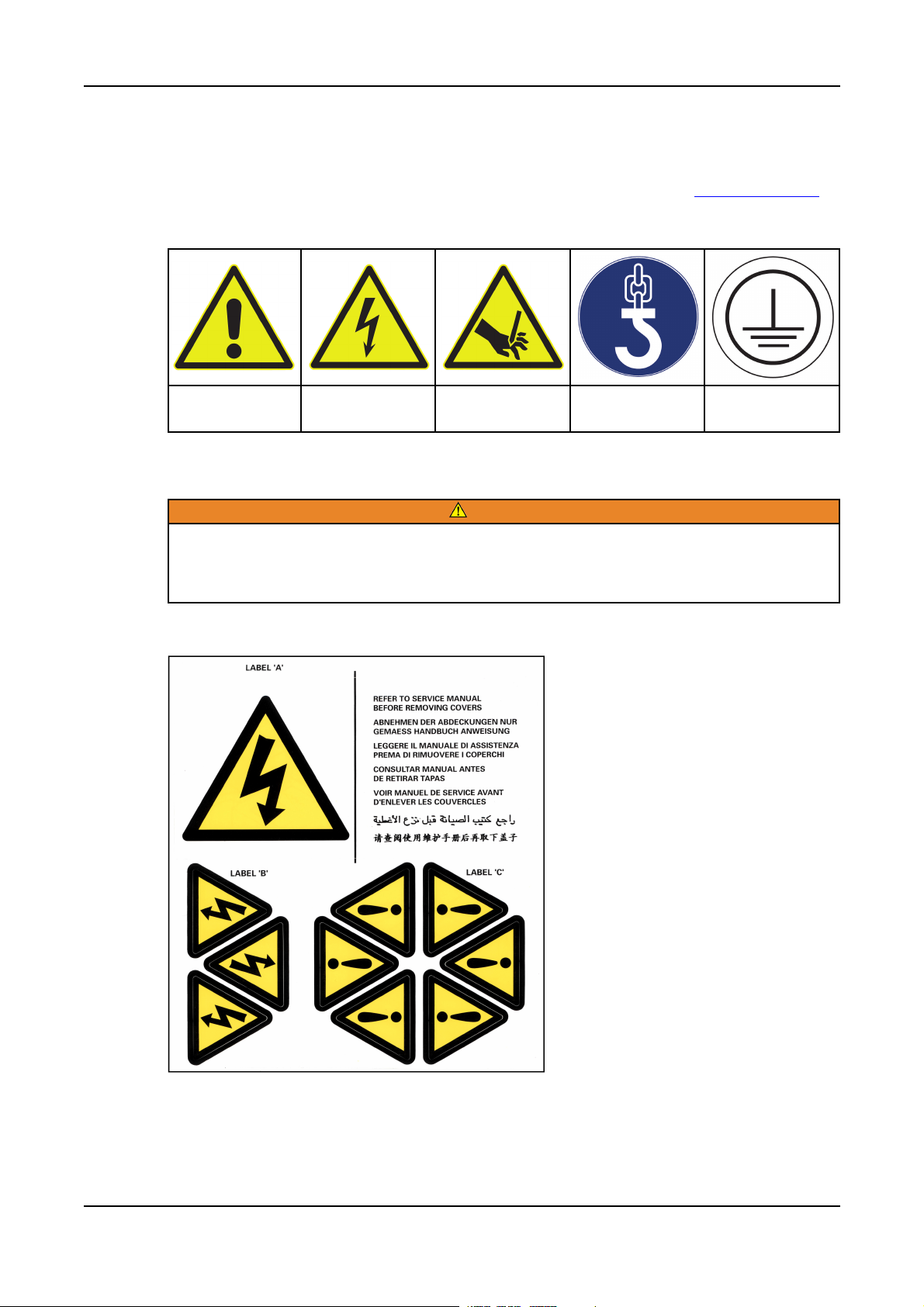
2.12 Safety Information Signs
Safety information signs are provided on the equipment to indicate hazards and emphasize
instructions. Become familiar with the signs and the meaning before operating the equipment. To
avoid injury, always take the necessary precautions. Sample signs are shown in Table 1 on page 7.
TABLE 1. SAFETY SIGN EXAMPLES
2. Safety Precautions03-2019
Warning Electrical Hazard Rotating Parts
2.12.1 Hazard Warning Labels
Hazard warning labels show the type and source of potential hazards. Observe the safety
labels to avoid risk of injury. The generator set manufacturer is responsible for fitting the
self-adhesive hazard warning labels supplied with the alternator. Labels must be fitted at the
locations shown on the back of the label sheet supplied with the alternator manual.
Replace labels that are missing, damaged or painted over.
WARNING
Mandatory
(Example: Lifting)
Protective
Conducter
7ING-WI-0395/A046V044 (Issue 7)

2. Safety Precautions 03-2019
2.13 Oils and Grease
CAUTION
Hazardous Substances
Misuse of oils, grease or other chemical substances can lead to serious injury
When handling oils, greases and other chemical substances pay attention to the safety
regulations, appropriate PPE and environmental regulations that apply.
2.13.1 Solvents and Substances Containing Solvents
NOTICE
Pay attention to the safety regulations on handling solvents. Ask the manufacturer of the
solvent for safety data sheets and first aid measures in case of emergency! The safety data
sheets must be available before using the solvent.
On handling solvents or substances containing solvents always wear protective equipment such as
safety glasses, safety shoes, hard hat, protective gloves and suitable protective clothing to protect the
skin. Always use barrier cream.
Only use solvents in well-ventilated areas. To keep the exposure and hazards as low as possible, you
should:
1. Seal solvent containers immediately after use
2. Ensure that solvent and its vapors are not inhaled.
Solvents are combustible and flammable! A flame is not necessarily required for ignition, ignition
can also be triggered by hot objects at temperatures above the ignition temperature of the
solvent, or by electrical sparks (pay attention to electrostatic charging).
3. Do not bring organic solvents into contact with oxidizing agents (risk of explosion).
4. Ensure adequate ventilation!
Solvent vapors are heavier than air and can collect on the ground or in hollows. There is a risk of
asphyxiation and explosion!
First aid:
After inhaling larger quantities: copious fresh air, seek medical attention.
After contact with the skin: rinse thoroughly with water.
In case of contact with the eyes: rinse using eye bath and seek medical attention from an
ophthalmologist.
After swallowing: Seek medical attention
2.14 General Guidance
NOTICE
These safety precautions are for general guidance and supplement your own safety
procedures and all applicable laws and standards.
8 ING-WI-0395/A046V044 (Issue 7)

2.14.1 General Safety Instructions
• Only use the alternator in correct working condition as well as in the manner intended, with due
consideration for safety and hazards while following the documentation and the local health and
safety regulations.
• Correct any malfunctions without delay that may affect safety or have them rectified by our
service organization.
• Always store this documentation with the alternator.
• Regularly check that personal work with due consideration for safety and hazards and follow the
documentation.
• Use appropriate personal protective equipment at all times
• Follow all information on safety and hazards on the alternator and maintain in legible condition.
• On the occurrence of safety-related changes on the alternator or in its operating behavior,
immediately shut down the alternator and correct malfunction without delay.
• Do not make any changes, additions or modifications to the alternator. This statement also
applies to installation and the settings for safety features.
• Do not circumvent or bypass any safety features. Before opening doors or covers for which the
use of a tool is required, the alternator must be shut down, electrically isolated and grounded.
2. Safety Precautions03-2019
• Service parts must comply with the technical requirements defined by the manufacturer. This
aspect is only ensured with genuine branded service parts. On the use of other service parts,
liability by the manufacturer is excluded.
• Do not make any changes to the program (software) in the programmable control system.
Changes to the program must only be made by appropriately trained personnel.
• Comply with stipulated intervals or intervals defined in the documentation for regular inspections
and servicing work.
• Use only appropriate tools for undertaking maintenance measures.
• Pay attention to fire alarm and firefighting procedures; pay attention to location and operation of
fire extinguishing systems (see Section 9.8 on page 74).
• Only allow trainees, apprentices or personnel under instruction or personnel undergoing general
training to work on the alternator under the constant supervision of an experienced person.
• Only task trained, experienced persons with the attachment of loads and signaling to crane
drivers. The person providing the signals must be visible for the operator.
• During installation work above head height, climbing aids and working platforms intended for this
purpose with appropriate safety features must be used. Do not use alternator components and
attachments as climbing aids! During servicing work at heights, wear fall arresting equipment.
• Keep all grips, steps, railing, pedestals, platforms, ladders free of debris and dirt.
• The alternator electrical equipment is to be checked regularly; loose connections or burnt,
damaged cables must be rectified immediately.
• If work is necessary on electrically live parts, involve a second person who can provide
immediate assistance in case of an emergency. Cordon off working area with a red-white safety
chain and a warning sign. Only use electrically insulated tools. Follow the local safety
regulations, e.g. VDE 0105
2.14.1.1 Safety Instructions for Normal Operation
• Refrain from all unsafe forms of working.
• Only operate the alternator if all protective devices and safety-related devices, e.g. detachable
protective devices, emergency stop devices, are fitted and functional.
• Inspect daily the alternator for externally visible damage and defects. Immediately report any
changes that have occurred (including changes in operating behavior) and immediately shut
down and secure the alternator.
9ING-WI-0395/A046V044 (Issue 7)

2. Safety Precautions 03-2019
• In case of malfunctions, immediately shut down and secure alternator. Correct malfunction
without delay.
• Follow the documented procedures for switching on and switching off.
• Before switching on/placing in operation the unit, make sure no-one will be placed at risk by the
starting machine.
2.14.1.2 Safety Instructions for Special Tasks
Observe adjustment, servicing and inspection activities and intervals stipulated in the documentation
including information on the replacement of parts/assemblies. Service and maintenance procedures
and tasks should only be carried out by experienced and qualified engineers, who are familiar with the
procedures and equipment.
• Before starting special tasks and maintenance work, inform the operators. Nominate supervisor.
• During all work related to the operation, the adjustment for production, the conversion or the
adjustment of the alternator and its safety-related features as well as inspection, servicing and
repair, pay attention to switching on and switching off procedures as per the documentation and
instructions on maintenance work.
• Mark and cordon off maintenance area as far as necessary.
• When the alternator is completely switched off for servicing and repair work, it must be secured
against unintended switching back on using Lock out / Tag out:
◦ Cordon off switch panel and attach a lock and tag to the main switch.
• Make sure individual parts, as well as larger assemblies, are fastened to lifting equipment and
secured on replacement so that they can cause no harm. Only use suitable lifting equipment in
correct working order with adequate load bearing capacity. Do not stand or work under
suspended loads.
• At the start of servicing / repair, clean alternator of dirt and residue of anti-corrosion agents. Do
not use aggressive cleaning agents. Use fluff-free cloths for cleaning.
• After cleaning, check all oil, compressed air lines for leaks, loose connections, chafing and
damage. Correct any defects found immediately.
• If it is necessary to remove safety features during set-up, servicing and repair, the safety
features must be re-fitted and checked immediately on completion of the servicing and repair
work.
• Ensure any materials used are disposed of safely with due consideration for the environment.
2.14.2 General Guidance for Use
Incorrect handling, hazardous voltages, rotating parts and hot surfaces will shock, burn or
cause loss of limbs or death.
Adhere to all safety instructions.
DANGER
Alternators have dangerous, live and rotating parts and hot surfaces. All work in relation to transport,
storage, installation, connection, commissioning, operation and servicing must be done by authorized,
trained specialist staff. National standards, e.g. EN 50 110-1 / DIN VDE 0105 / IEC 60364 are to be
followed in the specific case.
It is forbidden to place the unit in operation until the end product is compliant with local regulations
(follow in particular local safety and installation regulations, e.g. EN 60204).
These machines comply with the IEC EN 60034 series of standards. It is forbidden to use them in
potentially explosive atmospheres.
10 ING-WI-0395/A046V044 (Issue 7)

2. Safety Precautions03-2019
Under no circumstances use a degree of protection ≤ IP23 outdoors or in dusty environments.
Standard Air-cooled models are suitable for ambient temperatures from -15 °C to +40 °C and altitudes
of ≤ 1000 m above sea level. The ambient temperature for air/water-cooled models must not be less
than +5 °C without additional precautions. For alternators with sleeve bearings, the ambient
temperature must not be lower than 0° C. The oil temperature must be at least 15 °C for the start. (For
alternators with sleeve bearings also see the documentation from the bearing manufacturer). Pay
attention to any differing information on the rating plate. The conditions in the place of operation must
match all agreed information on the rating plate and in the specification.
In cases where there is a contradiction between the content of this manual and the machine supplied,
contact the manufacturer.
11ING-WI-0395/A046V044 (Issue 7)

2. Safety Precautions 03-2019
This page is intentionally blank.
12 ING-WI-0395/A046V044 (Issue 7)

3 Safety Directives and Standards
AvK alternators comply with European safety regulations as well as national and international
regulations on alternators issued in the EC. The alternator must be used in accordance with the
standards and intended use within the limits stated on the rating plate.
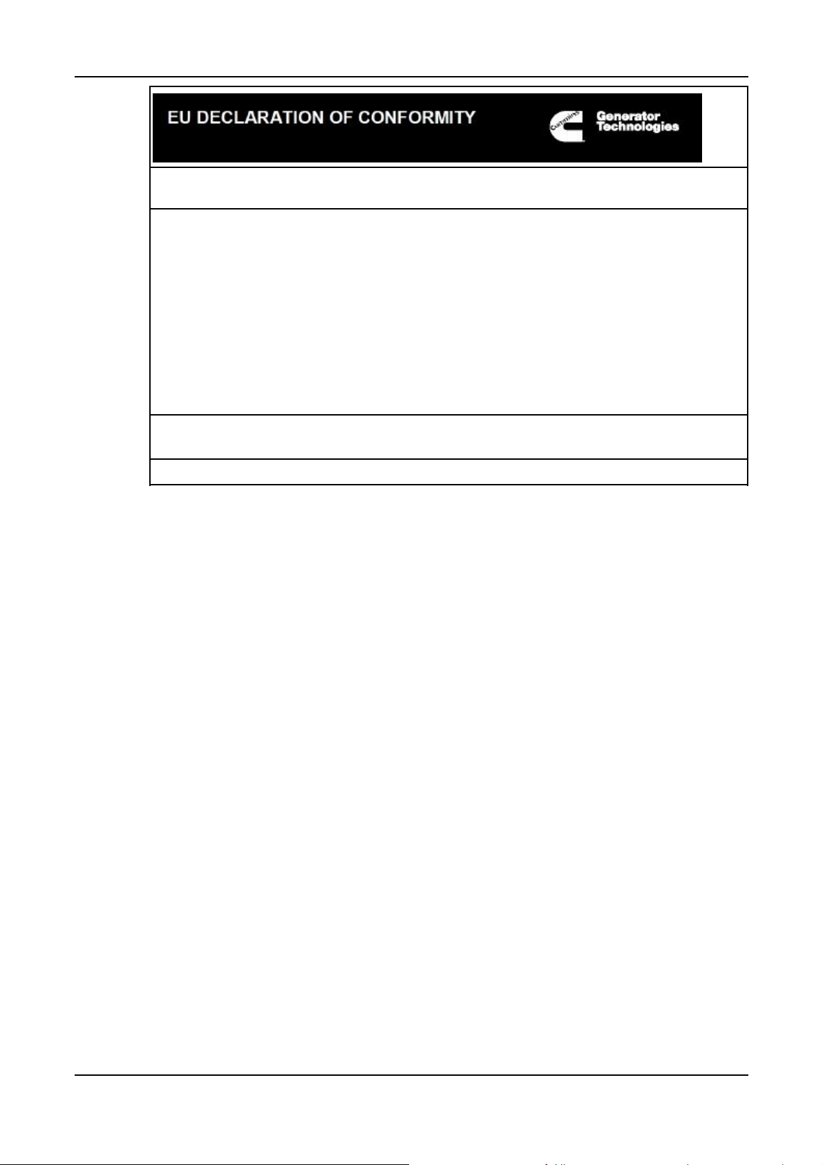
3.1 Low Voltage Directive: Declaration of Conformity Drawing
DSG alternators are supplied with an EC Declaration of Conformity. It is the responsibility of the
generator set manufacturer to ensure that the complete generator set complies with EC Directives and
Standards.
13ING-WI-0395/A046V044 (Issue 7)

3. Safety Directives and Standards 03-2019
TABLE 2. LOW VOLTAGE DIRECTIVE: DECLARATION OF CONFORMITY
This synchronous A.C. generator is designed for incorporation into an electricity generatingset and fulfils all the relevant provisions of the following EC Directive(s) when installed in
accordance with the installation instructions contained in the product documentation:
2014/35/EU
2014/30/EU
2011/65/EU
2015/863
Low Voltage Directive
The Electromagnetic Compatibility (EMC) Directive
Restrictions on Hazardous Substances in Electrical and Electronic
Equipment (RoHS) Directive
Delegated Directive amending Anex II of 2011/65/EU
and that the standards and/or technical specifications referenced below have been applied:
EN 61000-6-2:2005
EN 61000-6-
4:2007+A1:2011
EN ISO 12100:2010
EN 60034-1:2010
BS ISO 8528-3:2005
BS 5000-3:2006
EN 50581:2012
Electromagnetic compatibility (EMC). Generic standards – Part 6-2:
Immunity for industrial environments
Electromagnetic compatibility (EMC). Generic standards – Part 6-4:
Emission standard for industrial environments
Safety of machinery – General principles for design – Risk
assessment and risk reduction
Rotating electrical machines - Part 1: Rating and performance
Reciprocating internal combustion engine driven alternating current
generating sets - Part 3: Alternating current generators for generating
sets
Rotating electrical machines of particular types or for particular
applications - Part 3: Generators to be driven by reciprocating internal
combustion engines - Requirements for resistance to vibration
Technical documentation for the assessment of electrical and
electronic products with respect to the restriction of hazardous
substances
This declaration has been issued under the sole responsibility of the manufacturer. The
object of this Declaration is in conformity with the relevant Union harmonization Legislation.
The name and address of authorised representative, authorised to compile the relevant
technical documentation, is the Company Secretary, Cummins Generator Technologies
Romania, B-dul Decebal Nr. 116A 200746 Craiova Dolj, Romania.
Date: 06thMarch 2019
Name, Title and Address:
Kevan J Simon
Global Technical Director
Cummins Generator Technologies Romania
B-dul Decebal Nr.116A
200746, Craiova
Signed:
Dolj, ROMANIA
Description Serial Number
Cummins Generator Technologies Ltd. Registered Office: Fountain Court, Lynch Wood, Peterborough, UK, PE2 6FZ
Registered in England under Registration No. 441273.
DRAWING REF 450-16383-G
14 ING-WI-0395/A046V044 (Issue 7)
3. Safety Directives and Standards03-2019
The A.C. generator utilizes hazardous material exemptions as detailed in Annex III of EU Directive
2011/65/EU
Products carrying the following descriptions are considered to be out of scope of RoHS Directive
2011/65/EU, intended to be installed in Large Scale Fixed Installations and for installation into a predefined and dedicated location, installed and de-installed by professionals:
LVI80*
LVSI80*
DSG 99*
DSG 114*
DSG 125*
DSG 144*
Where * represents any combination of letters and characters completing the specific description of
the product.
Cummins Generator Technologies Ltd. Registered Office: Fountain Court, Lynch Wood, Peterborough, UK, PE2 6FZ
Registered in England under Registration No. 441273.
DRAWING REF 450-16383-G
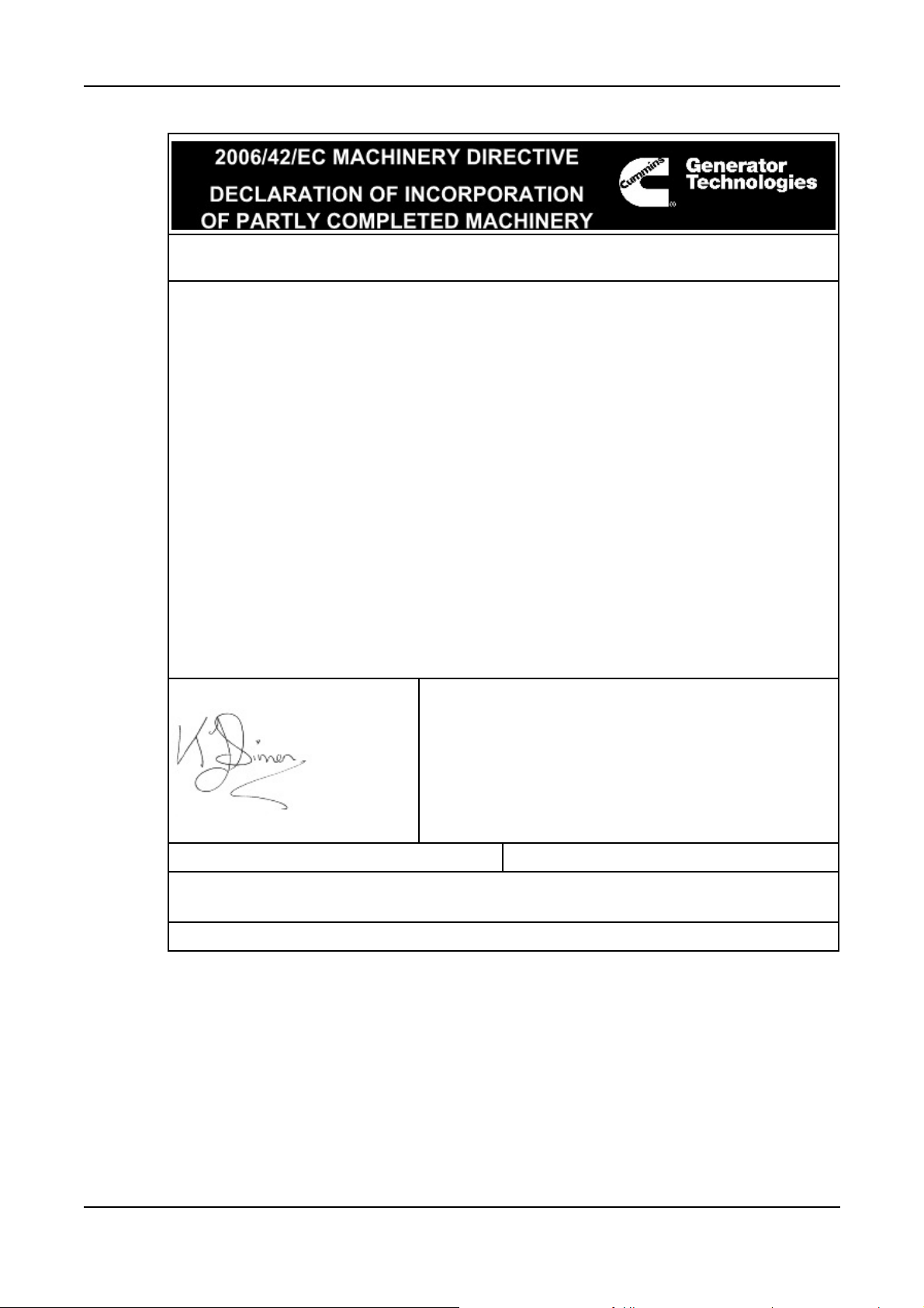
3.2 Machinery Directive: Declaration of Incorporation
DIG alternators are supplied with a "Declaration of Incorporation of Partly completed Machinery" for
incorporation into an electricity generating set. It is the responsibility of the generator set manufacturer
to ensure that the complete generator set complies with EC Directives and Standards.
15ING-WI-0395/A046V044 (Issue 7)
3. Safety Directives and Standards 03-2019
TABLE 3. MACHINERY DIRECTIVE: DECLARATION OF INCORPORATION - SHEET 1
Function: Synchronous A.C. generator designed for incorporation into an electricity
generating-set.
The partly completed machinery supplied with this declaration:
• Is designed and constructed solely as a non-functional component to be incorporated
into a machine requiring completion.
• Is designed to comply with the provisions of the following EU Directives so far as their
level of build will allow:
2014/30/EU The Electromagnetic Compatibility (EMC) Directive
• Must not be put into service within the European Community ("EC") until the final
machinery into which it is to be incorporated has been declared in conformity with the
Machinery Directive and all other applicable EC Directives.
• Is designed and constructed to comply with the essential health and safety
requirements of the Machinery Directive 2006/42/EC listed on sheet 2 of this Declaration.
The relevant technical documentation is compiled in accordance with the provisions of part B
of Annex VII of the Machinery Directive. All relevant information about the partly completed
machinery will be provided, in writing, on a reasoned request by the appropriate national
authority to its authorised representative. The name and address of authorised
representative, authorised to compile the relevant technical documentation, is the Company
Secretary, Cummins Generator Technologies Romania, B-dul Decebal Nr. 116 A 200746
Craiova Dolj, Romania.
The undersigned representing the manufacturer:
Date: 06thMarch 2019
Name, Title and Address:
Kevan J Simon
Global Technical Director
Cummins Generator Technologies Romania
B-dul Decebal Nr.116A
200746, Craiova
Signed:
Dolj, ROMANIA
Description Serial Number
Registered in England under Registration No. 441273.
Cummins Generator Technologies Ltd. Registered Office: Fountain Court, Lynch Wood, Peterborough, PE2 6FZ, England.
A048T564-D
16 ING-WI-0395/A046V044 (Issue 7)

3. Safety Directives and Standards03-2019
TABLE 4. MACHINERY DIRECTIVE: DECLARATION OF INCORPORATION - SHEET 2
ESSENTIAL HEALTH AND SAFETY REQUIREMENTS RELATING TO THE DESIGN AND
CONSTRUCTION OF PARTLY COMPLETED MACHINERY
1.1 General Remarks
• 1.1.2 : Principles of safety integration
• 1.1.3 : Materials and products
• 1.1.5 : Design of machinery to facilitate its handling
1.3 Protection Against Mechanical Hazards
• 1.3.1 : Risk of loss of stability
• 1.3.2 : Risk of break-up during operation
• 1.3.3 : Risks due to falling or ejected objects
• 1.3.4 : Risks due to surfaces, edges or angles
• 1.3.7 : Risks related to moving parts
• 1.3.8.1 : Moving transmission parts
1.4 Guarding
• 1.4.1 : Guards – General requirements
• 1.4.2.1 : Fixed guards
1.5 Other Hazards
• 1.5.2 : Static electricity
• 1.5.3 : Energy supply other than electric
• 1.5.4 : Errors of fitting
LEGEND
1. Essential Health and Safety
Requirements not shown are
not considered applicable for
this Partly Completed
Machinery or must be
fulfilled by the assembler of
the Machinery.
2. Essential Health and Safety
Requirements shown are
considered applicable for
this Partly Completed
Machinery and have been
fulfilled by the manufacturer
to the extent possible,
subject to the build
requirements of the
Machinery assembler, the
information contained in the
assembly instructions and
Cummins bulletins.
• 1.5.6 : Fire
• 1.5.13 : Emissions of hazardous materials and
substances
1.7 Information
• 1.7.1 : Information and warnings on the machinery
• 1.7.4 : Instructions
Registered in England under Registration No. 441273.
Cummins Generator Technologies Ltd. Registered Office: Fountain Court, Lynch Wood, Peterborough PE2 6FZ, England.
A048T564-D
17ING-WI-0395/A046V044 (Issue 7)

3. Safety Directives and Standards 03-2019
This page is intentionally blank.
18 ING-WI-0395/A046V044 (Issue 7)

4 Introduction
4.1 Serial Number
Each alternator is marked with a unique serial number. The serial number of this alternator is 81
34660 A001. It is marked on the rating plate on the alternator. (See Section 4.2 on page 19)
The serial number is to be stated in any future correspondence related to the alternator, as it is the
only information that is used to identify the specific alternator.
4.2 Rating Plate
Overheating
Can cause catastrophic failure and serious injury from ejected debris.
Always operate the alternator within the rated parameters specified on the rating plate .
A rating plate is permanently attached to the alternator and must not be removed. The rating plate
provides information on manufacture, identification, electrical and mechanical aspects.
WARNING
FIGURE 1. RATING PLATE
4.3 Important Remarks
In any areas of contradiction, the specific order-related documents take presidence.
In cases where there is a contradiction between the content of this manual and the alternator supplied,
contact Cummins Generator Technologies.
• The safety measures that are listed in the safety instructions in the manual must be observed at
all times.
NOTICE
19ING-WI-0395/A046V044 (Issue 7)

4. Introduction 03-2019
Safety in the workplace is dependent on the alertness, care and common sense of all persons who
operate and service the machines. Along with the safety precautions recommended here, caution is
always required in the vicinity of machines: Pay attention to your safety!
NOTICE
The installation must comply with the instructions and regulations for health and safety. This
statement applies for general safety regulations in the related country, specific agreements
made for the related works, safety instructions included in this manual, and separate safety
instructions supplied with the alternator.
4.4 Liability, Warranty and Guarantee
All data and information in this documentation is provided based on our past experience and
knowledge.
The technical information and data described in this documentation relate to the situation at the date
of publication. We reserve the right to make changes in the context of technical further development
without changing this documentation. It is therefore not possible to derive any claims from the data
and descriptions in this documentation.
We accept no liability for damage or interruptions to operation due to operating errors, failure to follow
the instructions, improper servicing or repair. The manufacturer is not liable under any circumstances
for direct, indirect, specific, accidental or consequential damage, irrespective of its nature, that results
from the application of this document; the manufacturer is also not liable for accidental or
consequential damage that results from the use of the alternator.
We specifically highlight that service parts and accessories not supplied by us must be approved by
the manufacturer of the alternator.
Any additional liability for damage resulting from the use of service parts and accessories that have
not been approved by the manufacturer is excluded by the manufacturer.
Liability covers manufacturing and material defects.
Liability for damage caused by improper storage, incorrect installation or incorrect operation of the
alternator is excluded, as are the resulting injuries to the personnel or third party damage.
The installation and the use of third-party products will degrade the design features of the electrical
machine and impair the safety of people, the system or other property.
Any unauthorized modifications or changes to the alternator are not allowed for safety reasons and
exclude liability on the part of the manufacturer for resulting damage. If attachments/parts provided by
the customer are to be installed in or on the alternator, this action must be done in consultation with
the manufacturer.
Warranty and liability conditions in the manufacturer's general terms and conditions are not expanded
by the above statements.
NOTICE
Claims cannot be made under the warranty if the operating conditions of the alternator have
been changed, changes have been made to the design of the alternator or repair work has
been done on the alternator without prior written agreement from the manufacturer.
20 ING-WI-0395/A046V044 (Issue 7)

4.5 Intended Use
4.5.1 Operating Conditions
4.5.1.1 Vibration Analysis
Serious damage (for example, destruction of the bearings, or cracks in the structure) may be
caused if the vibration allowed in the standard ISO 8528-9 or ISO 10816-3 is exceeded.
Serious damage (for example, destruction of the crankshaft, or destruction of the shaft) may
be caused if the torsional vibration is exceeded (e.g. ABS, LRS|). Ensure that the limits of the
Standards are adhered to.
It is the responsibility of the generating set builder to undertake the calculation, measurement and
evaluation of mechanical vibration in the power generating set (refer to standards ISO 8528-9 and ISO
10816-3).
It is imperative the rotational vibration calculation is made and checked.
4.5.1.2 Usage
4. Introduction03-2019
NOTICE
WARNING
Improper use.
Can cause hazards that could result in death or serious injury.
Always a operate in an accordance with the operation instructions.
NOTICE
Consult the manufacturer if you want to use the alternator in a different manner to that
described in the order documents.
The alternator is designed for onshore or maritime applications as per the order documentation.
4.5.1.3 Impermissible Forms of Operation
Do not operate the alternator:
• With operating data different to the data stated on the rating plate.
• With machine features modified by the operating organization.
• Outside the agreed specification
4.5.1.4 Permissible Forms of Operation
NOTICE
The alternator must only be used for the purpose stated in the order documentation. It must
be operated in accordance with the information in the documentation.
It is only allowed to operate the alternator
• In accordance with the procedures described in this documentation and
• If this documentation has been read and understood.
Any other use, as well as use involving hazardous or harmful substances is considered incorrect use.
21ING-WI-0395/A046V044 (Issue 7)

4. Introduction 03-2019
NOTICE
Damage caused by operation otherwise than as intended or by incorrect operation is not
covered by the manufacturer's warranty and guarantee obligations. The risk is borne solely
by the user.
We recommend that operating hours, malfunctions, inspections, servicing and repairs are documented
in a log.
If malfunctions or damage cannot be rectified by the operating organization's specialist personnel,
please contact our customer service department.
For details of your nearest service outlet visit www.stamford-avk.com.
4.6 Documentation
4.6.1 Additional Information
NOTICE
Some customer-specific elements can be found in the Appendices. If the information in this
manual does not match the information in the Appendices, the data in the supplementary
documentation in the Appendices applies.
In addition to this manual, each set of documentation is supplied with a dimension drawing and rotor
drawing, an electrical circuit diagram as well as data sheets that state, among others, the following
order-specific information:
1. External dimensions of the alternator
2. Alternator weight
3. Moment of inertia of the rotor
4. Position of the lifting eyes on the alternator
5. Instrumentation and position of additional equipment
6. Requirements on bearing oil and lubricants
7. Main and ancillary connections.
4.6.2 Information not included in the Documentation
This user manual does not contain any information on starting, protection or rotational speed control
features as this is not part of our delivery scope.
22 ING-WI-0395/A046V044 (Issue 7)
Loading...