

Page 1

Avision FB6000E Color Image Scanner
User’s Manual
Installing the Scanner
Installing the Software
Editing Your Image
Maintenance
Troubleshooting
i
Page 2

i
Trademarks
Microsoft is a U.S. registered trademark of Microsoft Corporation.
Windows and MS-DOS are trademarks of Microsoft Corporation.
IBM, PC, AT, XT are registered trademarks of International Business
Machines Corp.
Other brands and product names herein are trademarks or registered
trademarks of their respective holders.
Copyright
All rights reserved. No part of this publication may be reproduced,
transmitted, transcribed, stored in a retrieval system, or translated into
any language or computer language, in any form or by any means,
electronic, mechanical, magnetic, optical, chemical, manual, or
otherwise, without the prior written permission of Avision Inc.
Material scanned by this product may be protected by governmental
laws and other regulations, such as copyright laws, the customer is
solely responsible for complying with all such laws and regulations.
Warranty
The information contained in this document is subject to change
without notice.
Avision makes no warranty of any kind with regard to this material,
including, but not limited to, the implied warranties of fitness for a
particular purpose.
Avision shall not be liable for errors contained herein or for incidental
or consequential damages in connection with the furnishing,
performance, or use of this material.
i
Page 3

i
FCC Radio Frequency Interference
Statement
This equipment has been tested and found to comply with the limits
for a class B digital device, pursuant to Part 15 of the FCC rules.
These limits are designed to provide reasonable protection against
harmful interference in a residential installation. This equipment
generates, uses, and can radiate radio frequency energy and, if not
installed and used in accordance with the instruction manual, may
cause harmful interference to radio communication. However, there
is no guarantee that interference will not occur in a particular
installation. If this equipment does cause harmful interference to
radio or television reception, which can be determined by turning the
equipment off and on, the user is encouraged to try to correct the
interference by one or more of the following measures:
− Reorient or relocate the receiving antenna.
− Increase the separation between the equipment and receiver.
− Connect the equipment into an outlet on a circuit different from
that to which the receiver is connected.
− Consult the dealer or an experienced radio/TV technician for help.
FCC CAUTION: To assure continued compliance, (example - use
only shield interface cables when connecting to computer or
peripheral devices). Any changes or modifications not expressly
approved by the manufacture of this device could void the user's
authority to operate the equipment. This device complies with Part
15 of the FCC Rules. Operation is subject to the following two
conditions: (1) This device may not cause harmful interference, and
(2) this device must accept any interference received, including
interference that may cause undesired operation.
Responsible Party: Avision Labs, Inc.
Telephone No.: +1 (510) 739-2369
ii
Page 4

v
TABLE OF CONTENTS
1. INTRODUCTION ................................................ 1-1
2. SCANNER INSTALLATION ............................... 2-1
2.1 PRECAUTIONS ............................................................. 2-1
2.2 UNLOCKING YOUR SCANNER......................................... 2-2
2.3 SETTING SCSI ID........................................................ 2-3
2.4 SETTING SCSI TERMINATOR........................................ 2-3
2.5 SETTING SCSI SYNC SWITCH ..................................... 2-5
2.6 CONNECTING THE CABLES ........................................... 2-6
2.7 PLACING YOUR ORIGINAL ............................................. 2-7
3. SCANNER DRIVER INSTALLATION................. 3-1
3.1 SYSTEM REQUIREMENTS.............................................. 3-1
3.2 INSTALLATION STEPS ................................................... 3-1
3.3 SCANNING WITH IMAGE EDITING SOFTWARE .................. 3-2
3.4 A GLANCE OF THE USER INTERFACE............................. 3-4
4. EDITING YOUR IMAGE ..................................... 4-1
4.1 USING THE BASIC FEATURES....................................... 4-1
4.1.1 Choosing Your Scan Method ....................... 4-1
4.1.2 Selecting a Proper Image Type.................... 4-2
4.1.3 Determining a Proper Resolution ................. 4-4
4.1.4 Adjusting the Brightness and Contrast......... 4-5
4.1.5 Enlarging Previewed Image.......................... 4-6
4.1.6 Inverting and Selecting Your Image ............. 4-7
4.1.7 Enhancing Your Image................................. 4-9
i
Page 5

v
4.2
USING THE ADVANCED FEATURES ............................. 4-11
4.2.1 The Switch Button ...................................... 4-11
4.2.2 Adjusting Highlight/Shadow Levels ............ 4-12
4.2.3 Adjusting the Brightness Curve.................. 4-14
4.2.4 Changing Color Hue/Saturation/Lightness. 4-15
4.2.5 Using Color Balance................................... 4-16
4.2.6 Color Drop-out............................................ 4-17
4.3 USING OTHER TOOLS ................................................. 4-18
5. CARE AND MAINTENANCE.............................. 5-1
5.1 CLEANING THE GLASS ................................................. 5-1
6. TROUBLESHOOTING........................................ 6-1
6.1 FREQUENTLY ASKED QUESTIONS ................................. 6-1
6.2 TECHNICAL SERVICE................................................... 6-3
7. SPECIFICATIONS.............................................. 7-1
7.1 MODEL: FB6000E ..................................................... 7-1
INDEX ............................................................................A
Page 6

1. INTRODUCTION
Congratulations on your purchase of the Avision’s A3-sized color
image scanner. Avision is one of the leading companies to make high
quality color image scanner.
To ensure the optimum performance of the scanner, please take a
few minutes to read through this manual before you install and
operate the new scanner. The manual contains valuable
information on how to unpack, install, operate, and maintain the
scanner properly.
Figure 1-1 in below shows how the scanner is packed. Please
check if all items are included. If there is any item missing or
damaged, please contact your nearest dealer immediately for
replacement.
1-1
Page 7
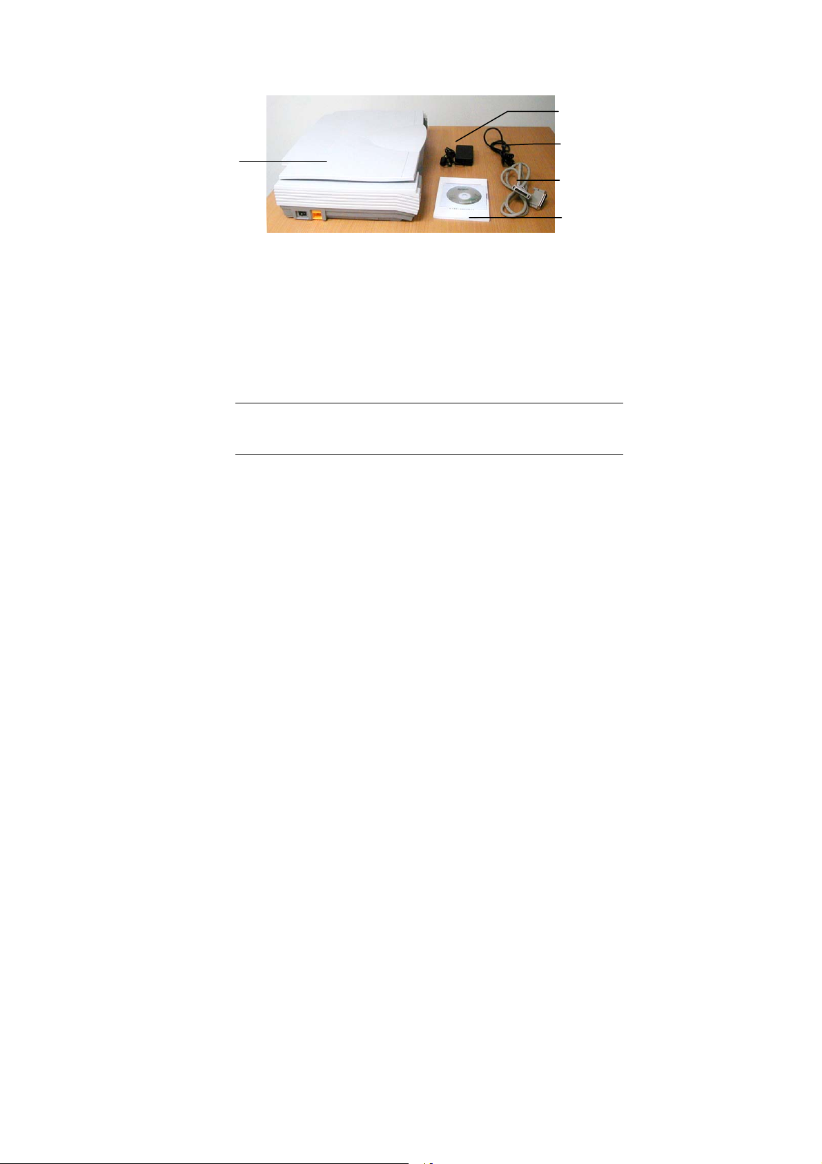
1
1. Scanner main unit
2. Power adapter
3. Power cord
4. SCSI cable
5. User’s manual/CD/SCSI card
Figure 1-1 Scanner Packaging
Note: When you unpack the scanner, retain the packing
material and shipping box in case you may transport the
scanner in the future.
2
3
4
5
4
5
6
1-2
Page 8

2. SCANNER INSTALLATION
2.1 PRECAUTIONS
¾ Keep the scanner out of direct sunlight. Direct exposure to the
sun or excessive heat may cause damage to the unit.
¾ Do not install the scanner in a humid or dusty place.
¾ Be sure to use the proper AC power source.
¾ Place the scanner securely on an even, flat surface. Tilted or
uneven surfaces may cause mechanical problems.
¾ Keep the shipping box and the material in case you may need to
ship the scanner again.
2-1
Page 9
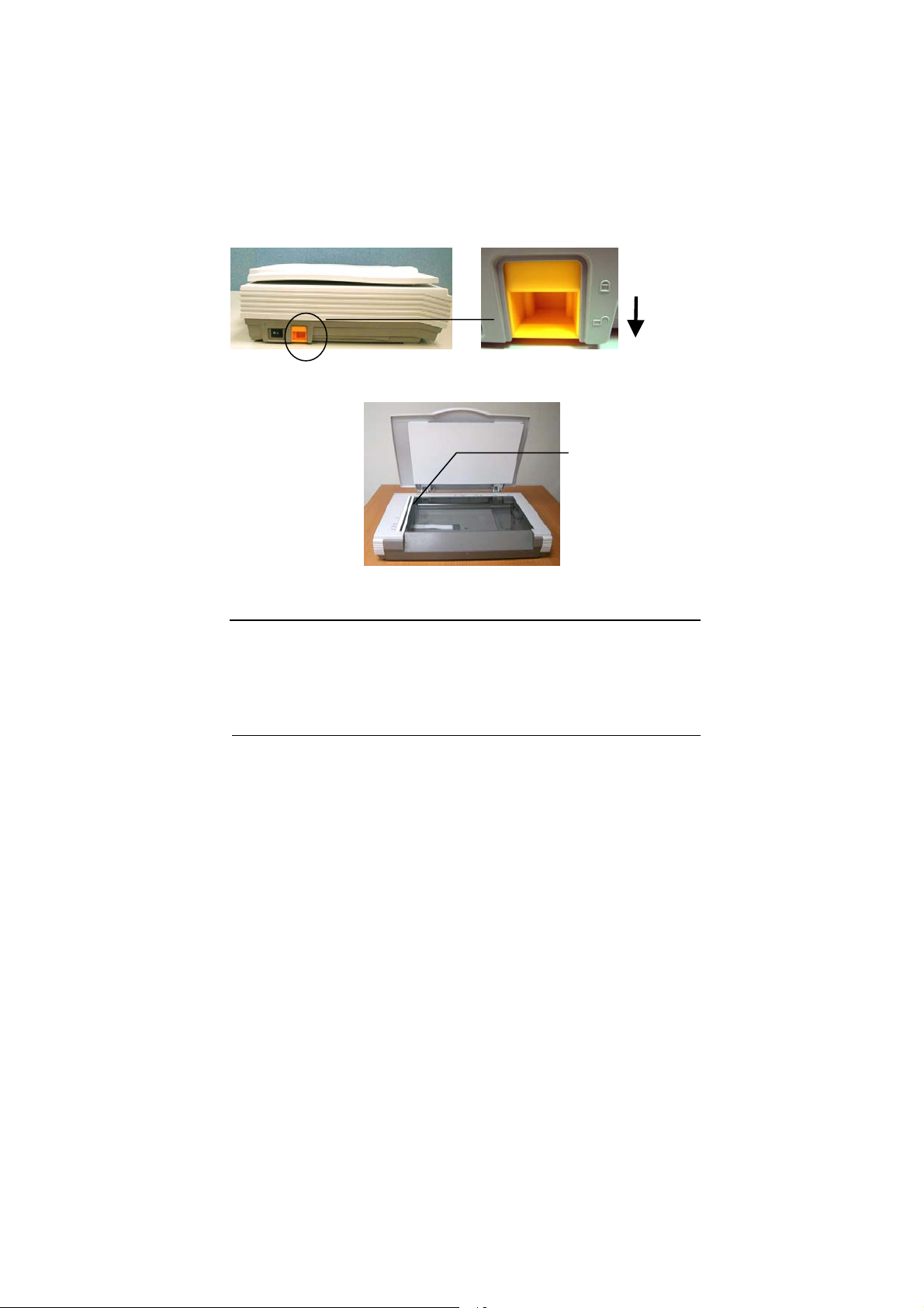
2.2 UNLOCKING YOUR SCANNER
To protect the scanning unit from damage during transportation, a
lock switch is designed at the back of the scanner to keep the
scanning unit from moving. To unlock the scanner, move the lock
switch up as shown in Fig. 2-1.
Locked
Unlocked
Figure 2-1 Unlocking the Scanner
Scanning unit at this
position before
locking the scanner
Figure 2-2 Home position
Note: If the scanning unit is not located at the front of the scanner
before transporting the scanner, be sure to do the follows:
1. Turn on the scanner.
2. The scanning unit should move to the front of the scanner.
3. Press the lock switch down to the “Lock position”.
4. The scanner is now ready to transport.
2-2
Page 10

2.3 SETTING SCSI ID
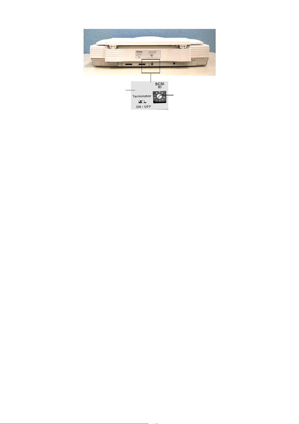
When you have several devices on a SCSI chain, you may have to
adjust the SCSI ID selector setting at the back of the scanner(See
Figure 2-2). This setting assigns a specific "device ID" to the
scanner. If the ID number is duplicated with an existing SCSI device
on the SCSI chain, please select a new ID#.
Note: The factory setting for the scanner is ID# 6. Usually, ID# 0 is
assigned to an internal hard disk drive, and ID# 7, to SCSI adapter or
host. ID# 8 and #9 are not in use.
2.4 SETTING SCSI TERMINATOR
The scanner is equipped with a built-in terminator switch on the rear
side of the scanner (See also Figure 2-2). Move the switch to the
“on” position to enable the SCSI termination or to the “off” position to
disable the SCSI termination. The SCSI termination ensures the
electrical signal flow through the SCSI chain properly.
As a result, if the scanner is the only or final device connected to
your computer, you should enable your SCSI chain terminates at the
scanner by moving the terminator switch to the “on” position. If your
scanner is linked between the host computer and other SCSI
devices, then the SCSI chain should terminate at the final SCSI
device. In the case, disable your SCSI termination on the scanner
by moving the terminator switch to “off” position.)
2-3
Page 11
2
1
1. SCSI ID Setting
2. SCSI Terminator Switch
Figure 2-2 SCSI ID setting/Terminator switch
2-4
Page 12
5
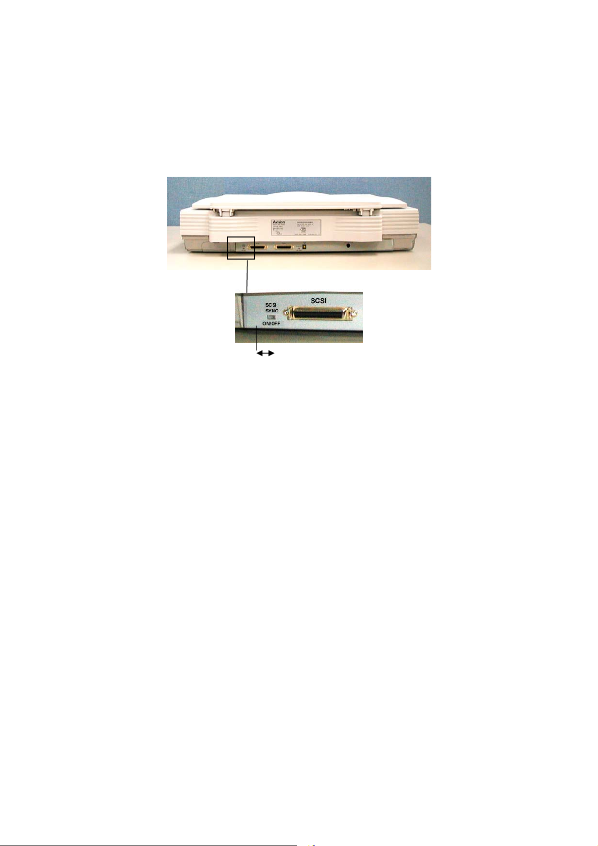
2.5 SETTING SCSI SYNC SWITCH
The scanner is designed with a SCSI SYNC switch at the rear of the
machine. The default setting is ”OFF”. If the SCSI card of your
computer supports SYNC, please move the SYNC switch at the rear
of the scanner to the “ON” position to make the data transmission
faster.
ON OFF
SYNC Switch
Figure 2-3 SCSI SYNC Switch
2-
Page 13
6
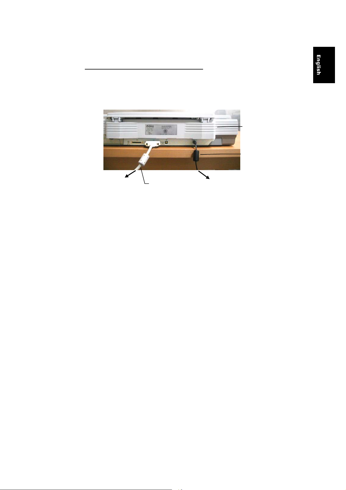
2.6 CONNECTING THE CABLES
Be sure the scanner power is switched off.
Connect the power cable and SCSI cable as shown in Figure 2-4.
Scanner
Power
cord
To a computer
SCSI cable
Figure 2-4 Cable Connection
To a power outlet
2-
Page 14
7
2.7 PLACING YOUR ORIGINAL
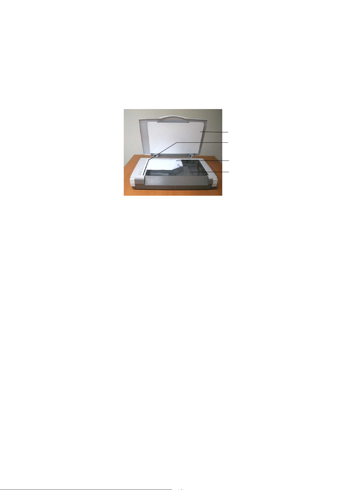
Open the document cover then place your original face down on the
document glass as shown in Fig. 2-5.
Make sure the top of your original near the document alignment
mark.
1
2
3
4
1. Document cover
2. Document alignment mark
3. Your original
4. Document glass
Figure 2-5 Placing the original
2-
Page 15

3. SCANNER DRIVER
INSTALLATION
3.1 SYSTEM REQUIREMENTS
To run the color image scanner at optimum speed, the following
minimum requirements are recommended:
• IBM compatible PC Pentium III 600 or above;
• Windows 95, Windows 98, Windows ME;
• One SCSI card installed one your computer;
• 100M bytes of available hard disk space for installation;
• 128M bytes of RAM or above;
• A video graphics array (VGA) monitor;
• A Microsoft Windows-compatible pointing device (e.g.,
the mouse);
• A CD-ROM drive.
3.2 INSTALLATION STEPS
1. Start Windows 98 / 98SE / Me / 2000 / XP.
2. Insert the supplied CD-ROM into your CD-ROM drive.
3. An installation menu will be automatically displayed. If the
installation menu has not been automatically displayed on your
screen, please press the “Start” button and choose RUN, type
“d:\cdsetup.exe” (“d:” the CD-ROM drive letter in use). Choose
“OK”.
4. Follow on-screen instructions to complete the installation.
3-1
Page 16
3.3 SCANNING WITH IMAGE EDITING SOFTWARE
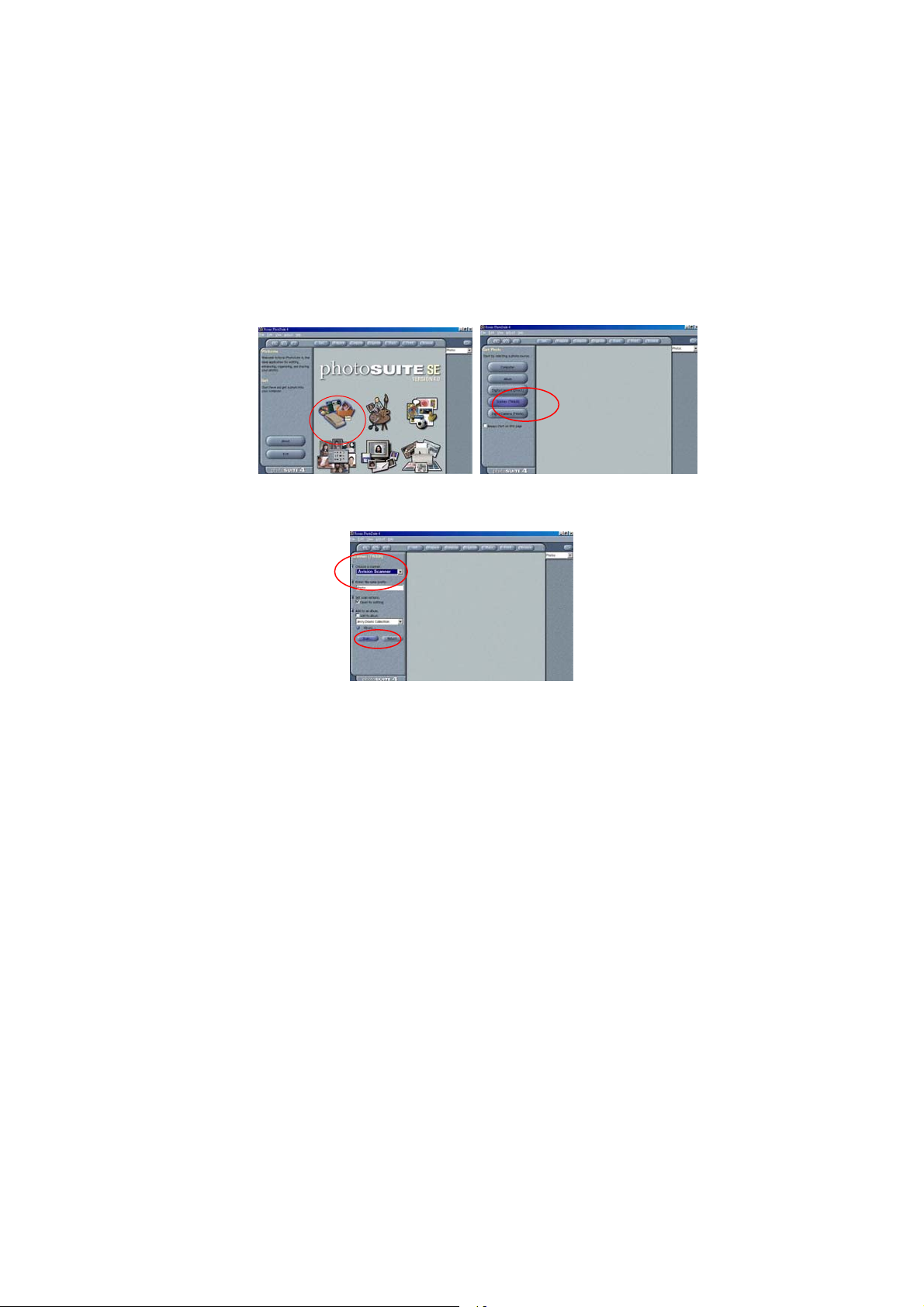
The scanner driver is not a stand-alone program, it has to be started
from within a TWAIN-compliant or plug-in software application and
then the scanner driver is able to scan and load the image to your
computer. The command to start the scanner driver may vary due to
different software applications.
1. Start a TWAIN compliant software application such as Roxio
PhotoSuite 4 SE which is bundled in the CD.
2. Click Get>Scanner (TWAIN).
3. Choose FB6000E as your scanning source. (You only need
to do this once.)
4. Place the document FACE DOWN on the document glass.
5. Click the Scan button to prompt the TWAIN user interface.
6. Click Preview to get an initial scan of your document.
Allocate your scanned area and choose Scan button to scan
the document.
3-2
Page 17
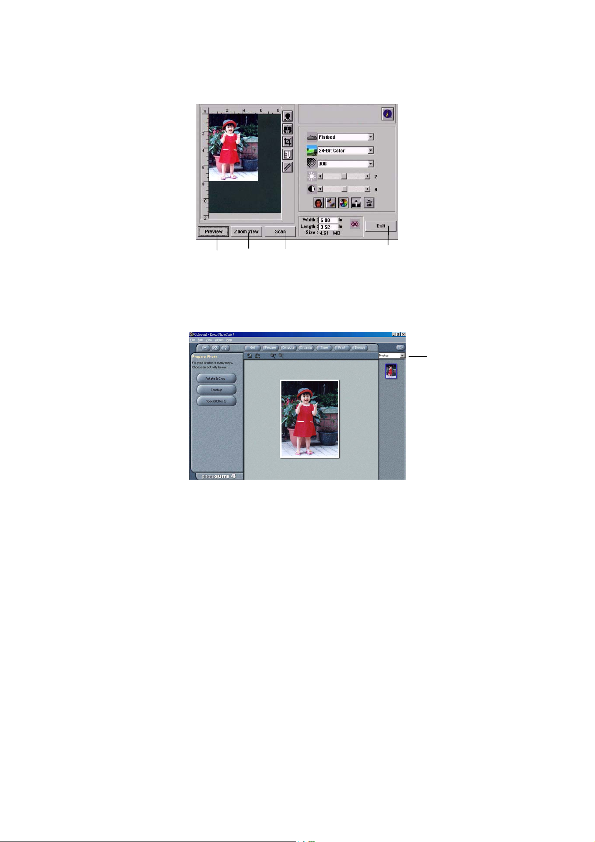
7. Click Exit to return to the main screen and click Open
Library and Photos at the upper-right corner to open your
scanned image.
1
2
1. Preview
2. Zoom View
3. Scan
4. Exit
5. Photos
3
4
5
3-3
Page 18
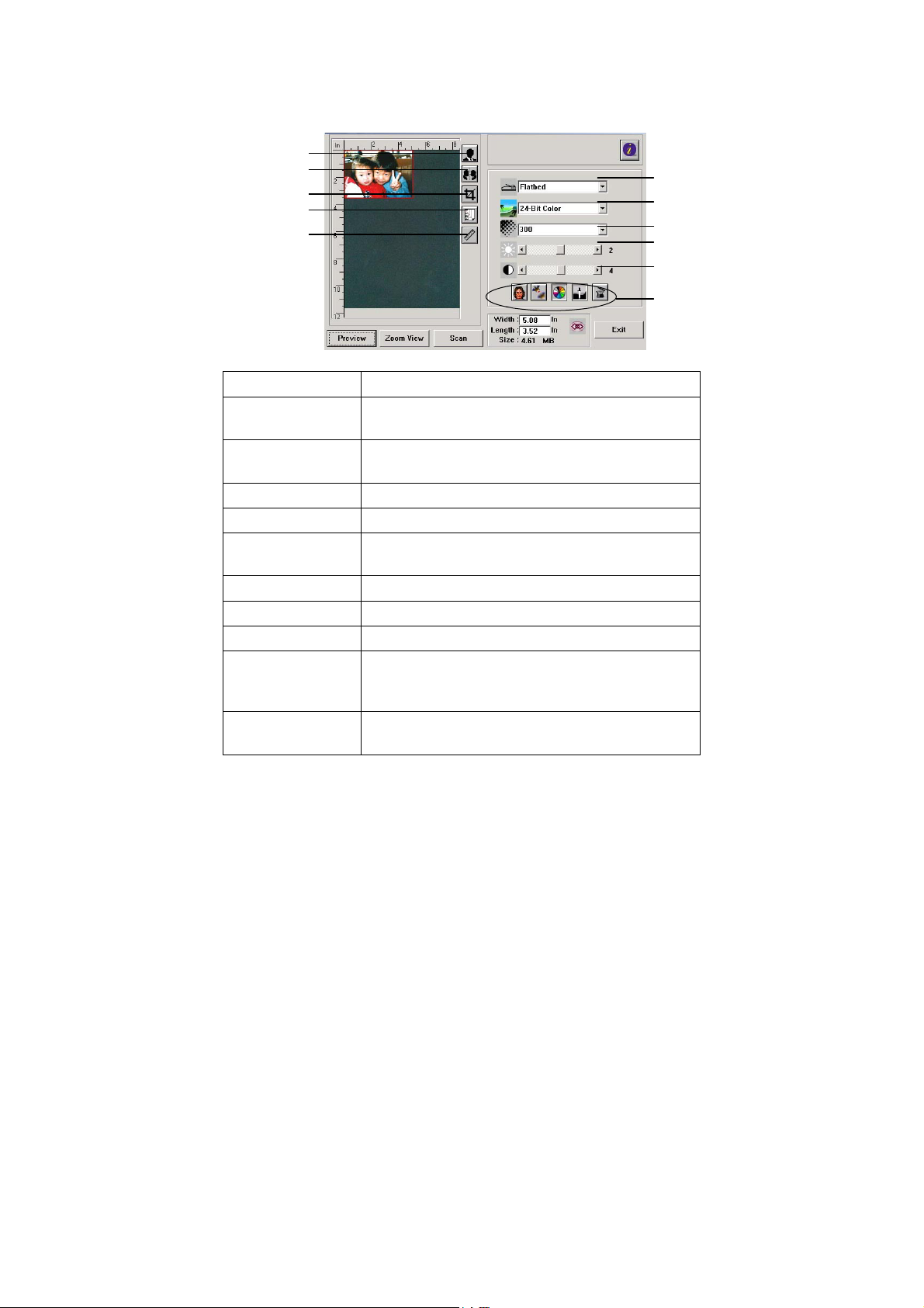
3.4 A GLANCE OF THE USER INTERFACE
7
8
9
10
11
1
2
3
4
5
6
1. Original Source Choice: Flatbed
2. Image Type Choice: Black & White, Halftone, 8-bit Gray, 8-
bit Color, 24-bit Color.
3. Resolution Choice: 50, 72, 100, 144, 150, 200, 300, 600
(dpi).
4. Brightness:
5. Contrast
6. Further Tools
Adjust the brightness level from –100 to +100.
Adjust the contrast level from –100 to +100.
Descreen, Sharpen, Color Adjustment, Auto
Level , Advanced Settings (From left to right).
7. Invert
8. Mirror Function
9. Crop
10. Paper Size
Reverse the color of your scanned image.
Flap your image.
Resize your scanned area.
Select your paper size from Card 4”x2.5”, Photo
5”x3”, Photo 6”x4”, A5, B5, A4, Letter, Legal, or
scanner maximum.
11. Measuring
Choice: cm, Inch, and Pixel.
Unit
3-4
Page 19
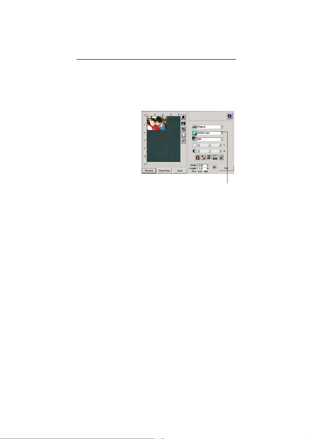
4. EDITING YOUR IMAGE
4.1 USING THE BASIC FEATURES
4.1.1 CHOOSING YOUR SCAN METHOD
1. Scan Method
Choice:
Flatbed: Chose this
mode to scan your
document or photo.
4-1
Page 20
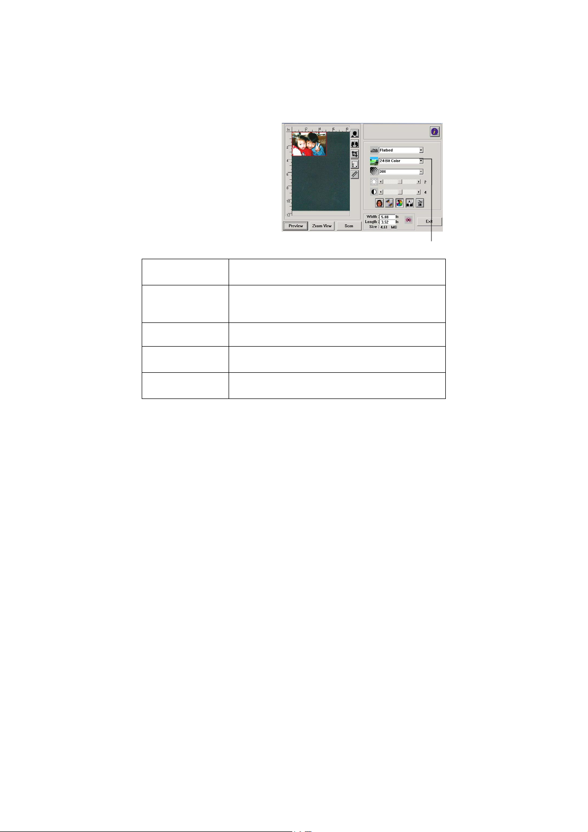
4.1.2 SELECTING A PROPER IMAGE TYPE
1. Image Type
Please see following table
for a choice of an ideal
image type.
Black & White
Halftone
8-bit Gray
8-bit Color
24-bit Color
Choose B&W if your original contains only B&W
text, pencil or ink sketch.
Halftones are reproduction of image that gives
the illusion gray. An example of halftone imaged
would be the pictures you see in newspapers.
8-bit Gray images contain actual shades of gray.
8-bit Color image provides 256 levels of color
hues.
Choose 24-bit Color if you wish to scan a color
image.
4-2
Page 21
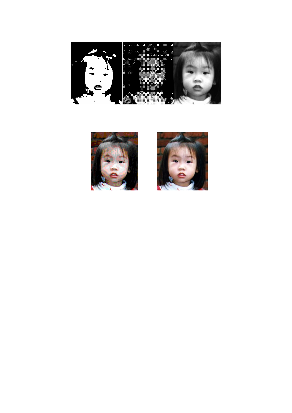
Black & White Halftone Gray
8-bit Color 24- bit Color
4-3
Page 22
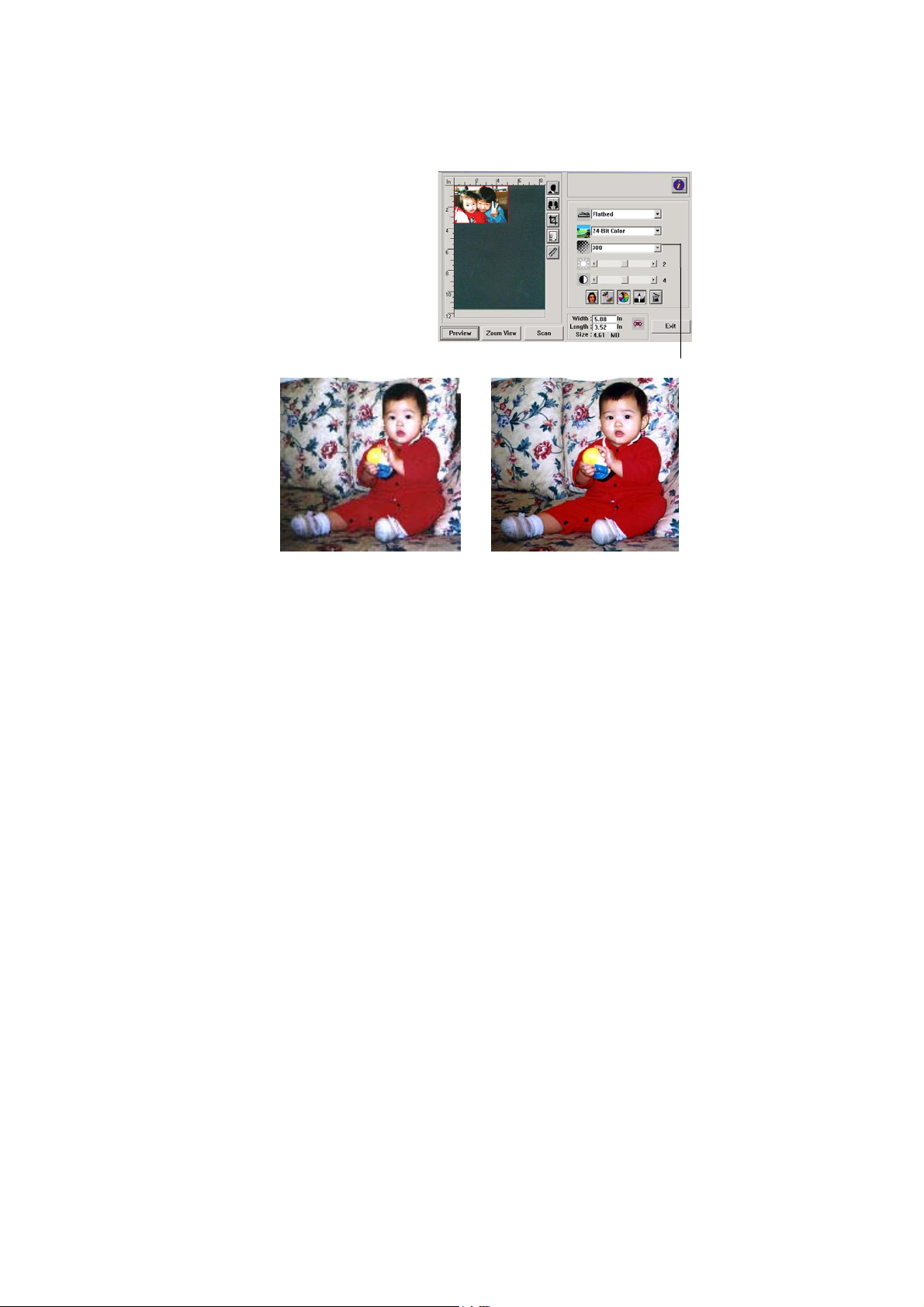
4.1.3 DETERMINING A PROPER RESOLUTION
1. Resolution
A proper resolution
reproduces a clear
image with good details.
The resolution is
measured by dots per
inch (dpi).
Resolution: 50 dpi
Resolution: 100 dpi
Note
For your information, an A4 size color image scanned at 300 dpi at
True Color mode consumes approximately 25 MB of disk space. A
higher resolution (usually means over 600 dpi) is only recommended
when you need to scan a small area at True Color mode.
4-4
Page 23
5
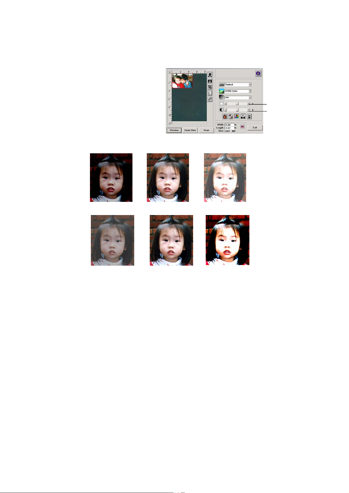
4.1.4 ADJUSTING THE BRIGHTNESS AND CONTRAST
1. Brightness
Adjusts the lightness or
darkness of an image.
The higher the value, the
brighter the image.
2. Contrast
Adjusts the range
between the darkest and
the lightest shades in the
image. The higher the
contrast, the bigger the
different grayscale.
Decrease Brightness Normal Increase Brightness
Decrease Contrast Normal Increase Contrast
1
2
4-
Page 24
6
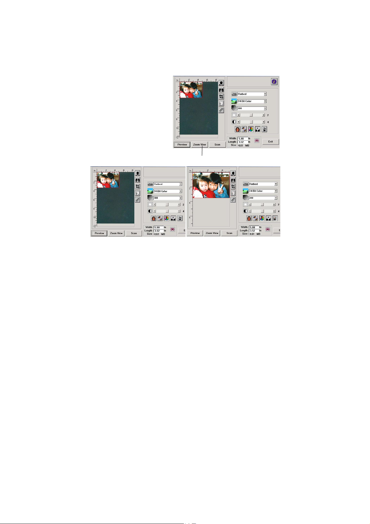
4.1.5 ENLARGING PREVIEWED IMAGE
1. Zoom View
Enlarge your previewed
image to the max. of the
preview window.
Note this function only
enlarging your preview
image. This does not
enlarge your real
image.
1
Before Zoom After Zoom
4-
Page 25
7
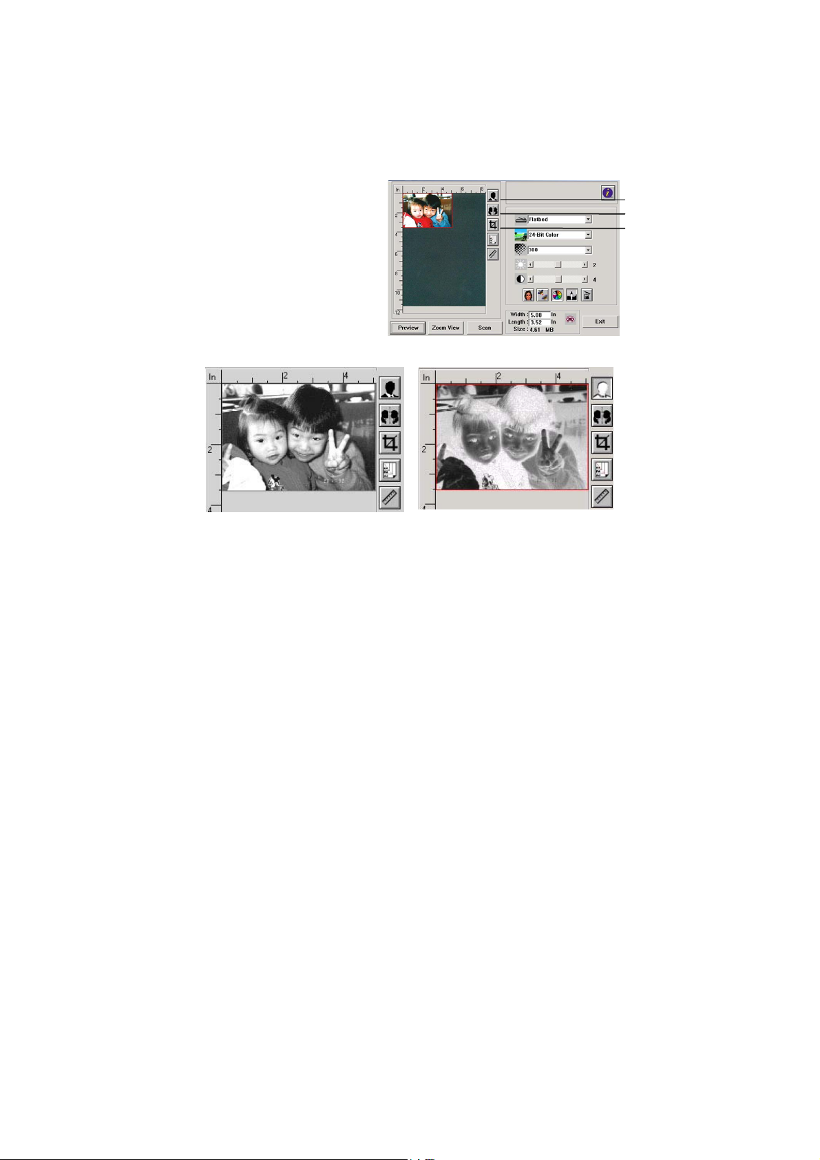
4.1.6 INVERTING AND SELECTING YOUR IMAGE
1. Invert
The invert command
reverses the brightness
and the color in the
image. For color images,
each pixel will be
changed into its
complementary color at
the command of Invert.
1
2
3
Before Invert After Invert
4-
Page 26

8
2. Mirror Function
Reverse the right and left side of your image.
Before Mirror After Mirror
3. Auto Select Image
Automatically set the whole image as your scan area. (Or you
may resize the area by “drag and drop” diagonally.)
4-
Page 27
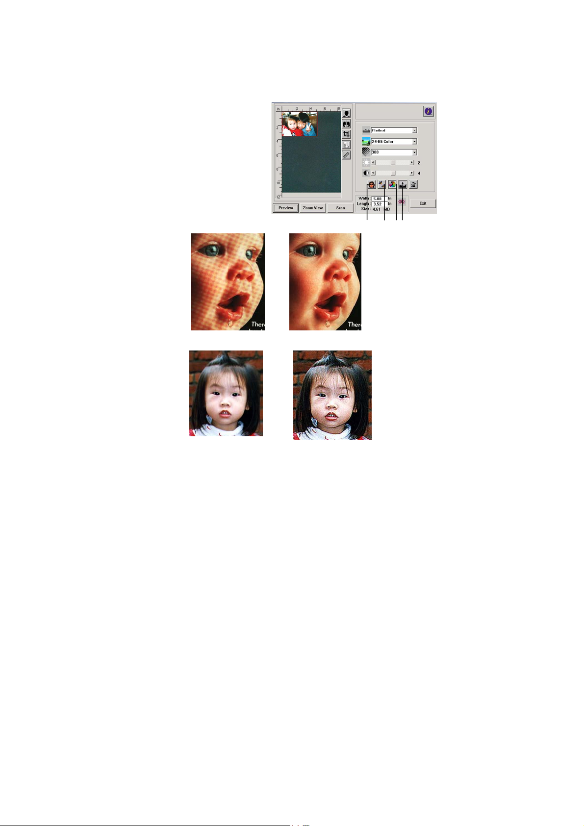
4.1.7 ENHANCING YOUR IMAGE
1. Descreen
Eliminates the
patterns* commonly
found in printed
matter.
2. Sharpen
Sharpen the scanned
image.
Before Descreen After Descreen
moire
1 2 3 4
Before Sharpen
After Sharpen
*Moire pattern: An undesirable pattern in a color printing resulting
from incorrect screen angle of overprinting halftone.
4-9
Page 28
0
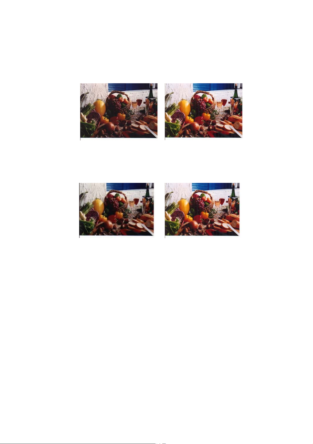
3. Color Adjustment
Adjusts the color quality of the image so that it comes close to
the original. This function uses default parameters to adjust
the image.
Normal
After Color Matching
4. Auto Level
Automatically adjusts the highlight and shadow areas of the
scanned image to optimize your image.
Normal
After Auto Level
4-1
Page 29
4.2 USING THE ADVANCED FEATURES
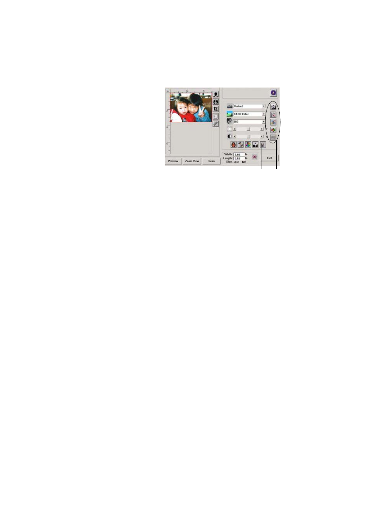
4.2.1 THE SWITCH
BUTTON
1. Click the button to pop
up the advanced settings
bar at the right side. The
advanced settings include
Highlight/Shadow,
Hue/Saturation/Lightness,
Curve, Color Balance,
Color Drop-out.
2. The Advanced
Settings bar
2
1
4-11
Page 30
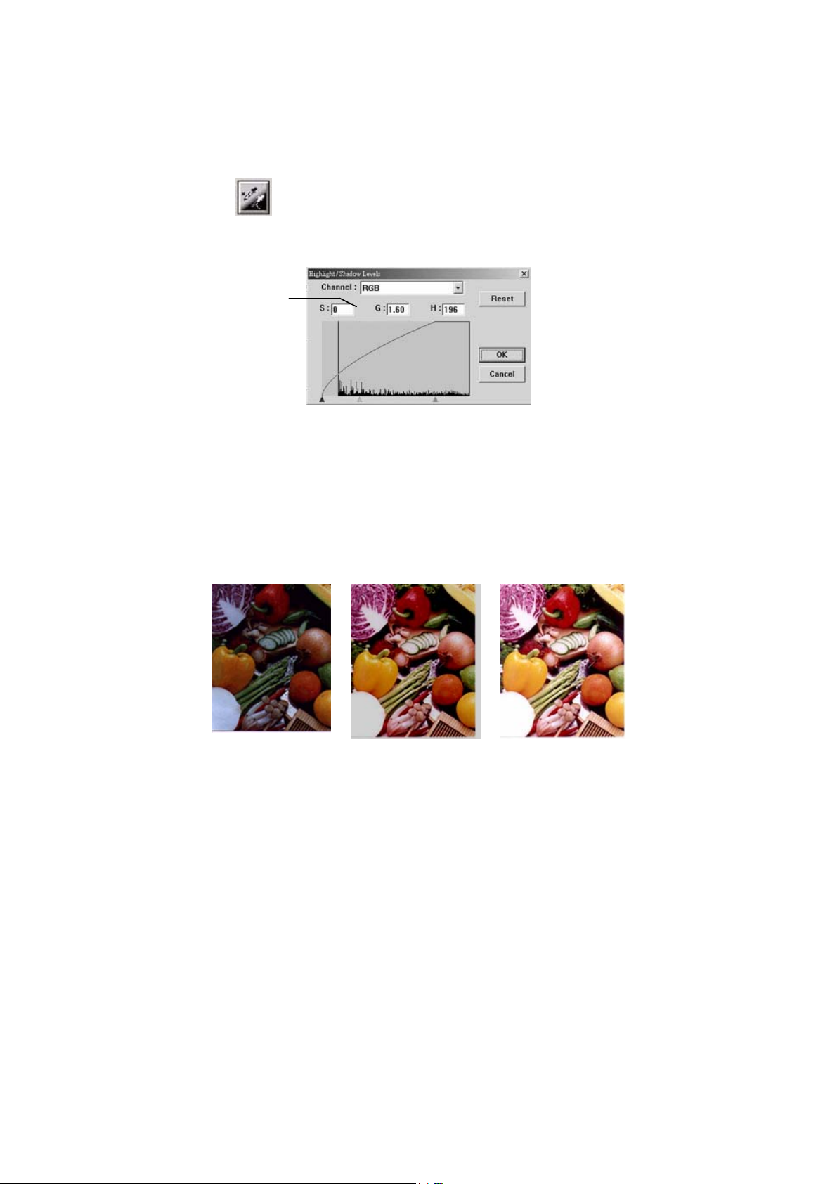
4.2.2 ADJUSTING HIGHLIGHT/SHADOW LEVELS
Highlight refers the lightest point in a scanned image
while shadow refers the darkest point. Using
Highlight and Shadow tool together allows you to
extend the range of color and reveal more details in a
gray or color image.
1
2
3
1. Shadow: The darkest point of an image.
2. Gamma: The midtones of the image.
3. Highlight: The lightest point of an image.
4. Pointer: Move the pointer to change the value.
When the value of gamma changes, the image changes
accordingly.
Gamma Value: 1.0
Gamma Value: 1.4
Gamma Value: 2.0
4-12
4
Page 31
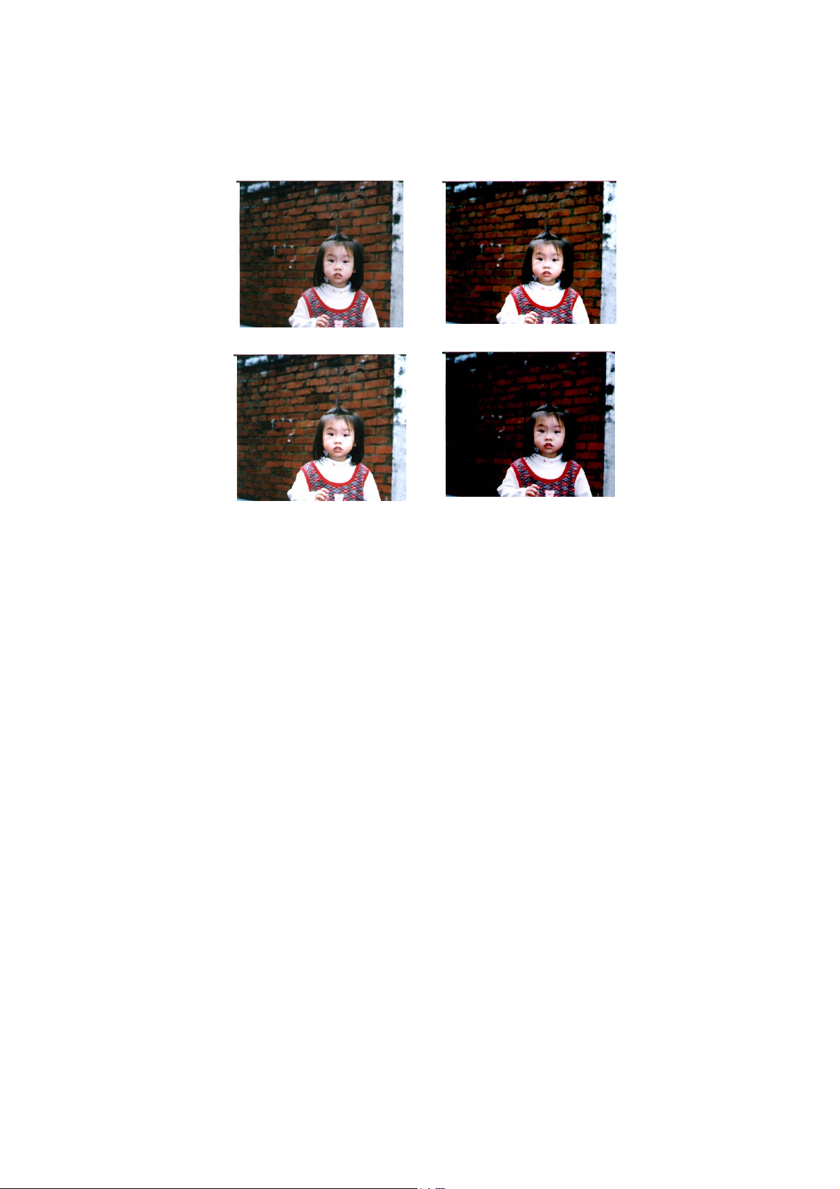
When the value of highlight and shadow change, the image
changes accordingly.
Highlight: 255/Shadow: 0(Normal)
Highlight: 200/Shadow:0
Highlight: 210/Shadow:10
Highlight: 255/Shadow: 50
4-13
Page 32
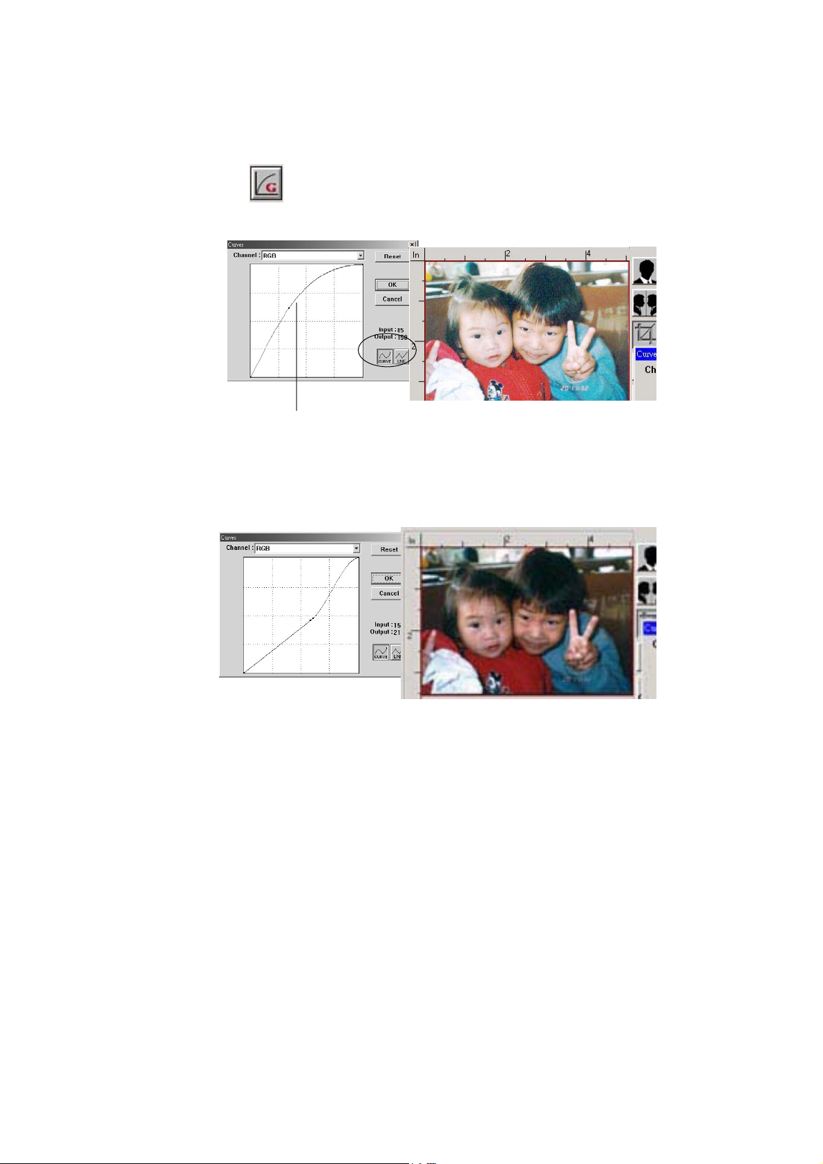
4.2.3 ADJUSTING THE BRIGHTNESS CURVE
Adjusts the midtones of the image without
dramatically altering then lightest and the darkest
areas.
When the curve is moved up or down, the image turn
brighter or darker.
4-14
Page 33
5
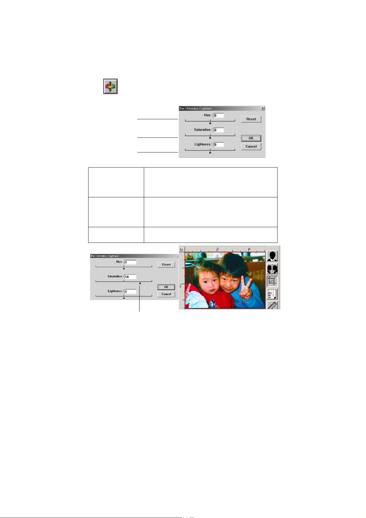
4.2.4 CHANGING COLOR HUE/SATURATION/LIGHTNESS
Improve your image by changing the level of
hue/saturation/lightness.
(1). Hue
(2). Saturation
(3). Lightness
(1)
(2)
(3)
Adjust the hue by moving the triangle to the
right or left. (Note the level of intensity for the
color will be changed simultaneously when the
hue adjustment is made).
Move the triangle to the right to increase the
saturation level or to the left to decrease the
level. The level of saturation decides if the color
is pale or rich.
Increase the lightness by moving the triangle to
the right or to the left to decrease the lightness.
Move the Saturation pointer to the right, the color turns rich.
4-1
Page 34
6
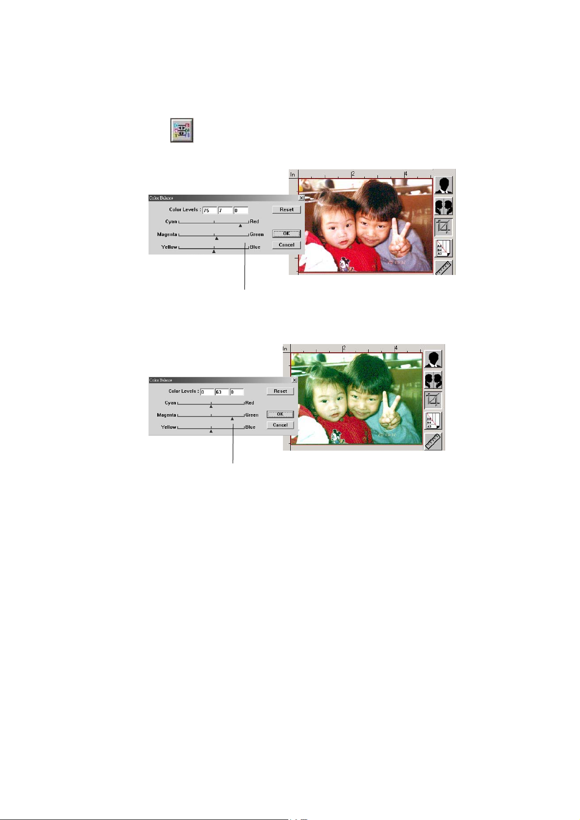
4.2.5 USING COLOR BALANCE
The Color Balance allows you to obtain an optimal
image quality.
Move the pointer toward Red, the image turns
into a reddish hue.
Move the pointer toward Green, the image
turns into a greenish hue.
4-1
Page 35
7
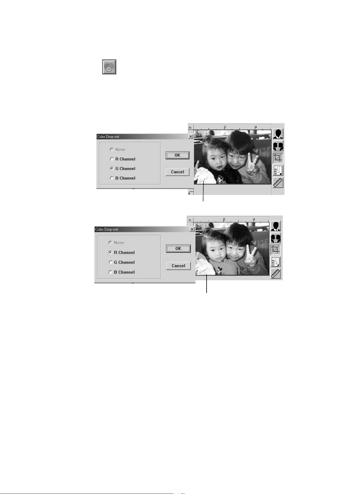
4.2.6 COLOR DROP-OUT
Click the button and a dialog box in below will be
displayed. This dialog allows you to remove one of
the R (Red), G (Green), or B (Blue) color channel.
This function is particularly useful when you need to
convert text using OCR software.
Note that this function supports only black & white and
gray image. Therefore, be sure to choose any black &
white or gray image type while applying this function.
The effect on image after removing the G channel.
The effect on image after removing the R channel.
4-1
Page 36
8
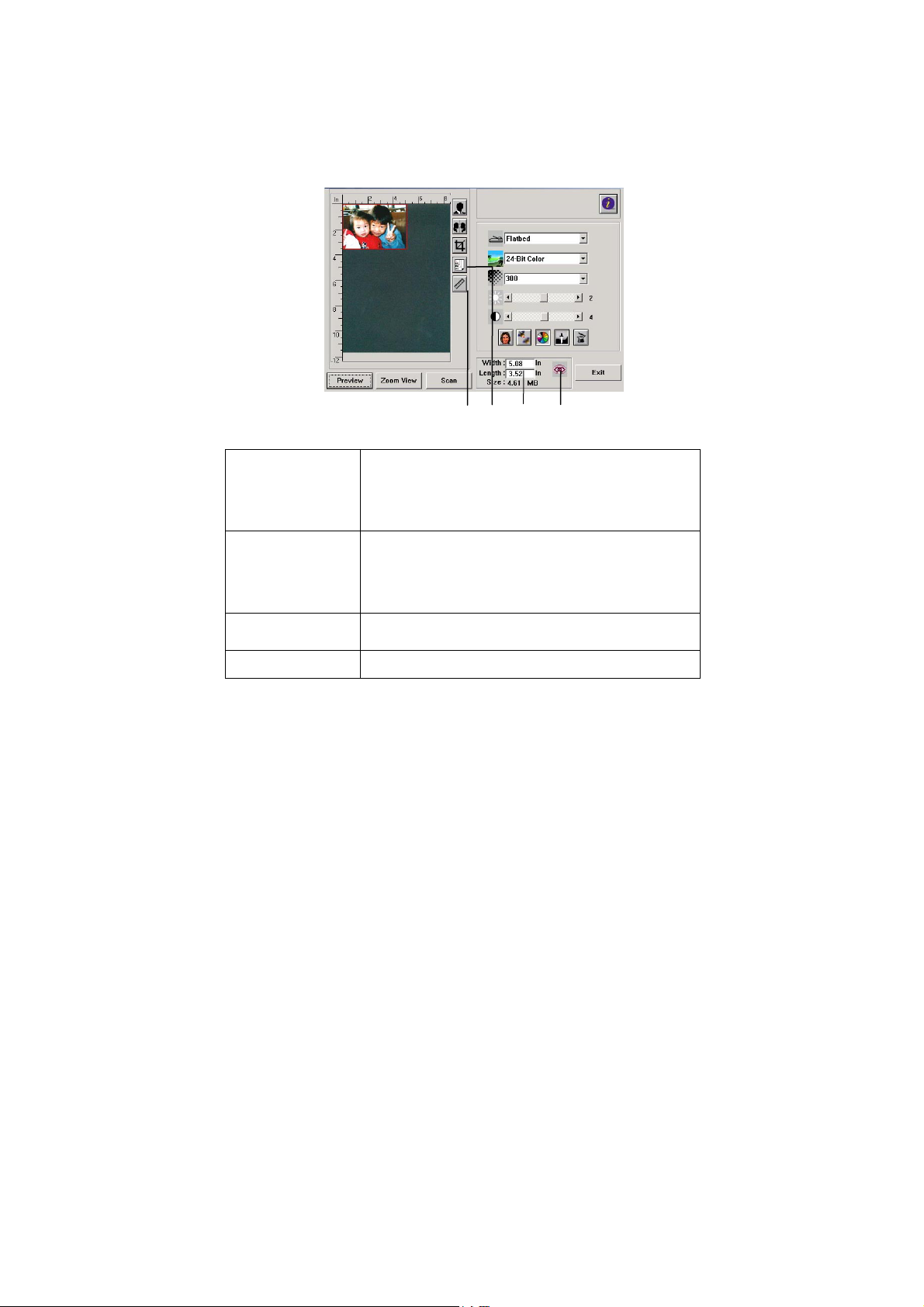
4.3 USING OTHER TOOLS
1. Measuring
Unit
2. Paper Size
3. Image Size
4. Lock Image
1 2 3
4
A reminder of the measuring system in use. By
clicking the button, you can change the
measuring unit.
Choice: Inch, cm, Pixel.
Provide frequently scan sizes.
Choice: Card 4”x2.5”, Photo 5”x3”, Photo
6”x4”, B5, A5, A4, Letter, and Scanner
Maximum.
Display image size for the scanned area.
Fix your output width and height.
4-1
Page 37
5. CARE AND MAINTENANCE
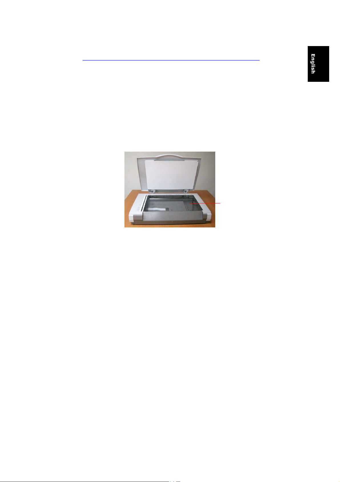
5.1 CLEANING THE GLASS
The procedures
1) Soak a cotton swab with some isopropyl alcohol. (95%)
2) Open the document cover as shown in Figure 5-1. Wipe the
document glass by moving the swab from side to side.
3) Close the document cover. Your scanner is now ready for use.
1
1. Document glass
Figure 5-1 The cleaning area
5-1
Page 38

6. TROUBLESHOOTING
If you have problems with the operation of your scanner, please
check the following troubleshooting hints.
6.1 FREQUENTLY ASKED QUESTIONS
Question: When the scanner is powered on, it makes noises
and won’t stand ready.
Answer: There are two possibilities:
1) You might fail to push the scanner shipping lock to its
“use” position. If this is the case, pull the scanner
status switch to its “use” position first.
2) The scanner is not placed on an even, flat desktop
surface. This may cause the scanner to malfunction.
Question: The scanner is powered on, but the lamp does not
light up.
Answer: The lamp is probably out of order. Contact your local
dealer or distributor to replace the lamp. For your
information, the average life time of the lamp is about
15,000 hours and the operating temperature for the
scanner is between 10°C(50°F)
and 40°C(104°F).
6-1
Page 39

Question: To get image from the scanner is no problem. But
when scanning, the scanner or the system will often crash.
Answer: 1) Please check if the cable is firmly seated.
2) Please note only two SCSI terminators can be
connected to your SCSI daisy chain. One is at the end
of the SCSI device, the other already in your host
adapter.
Question: While scanning, the scanner often makes noises,
or it scans back and forth.
Answer: Usually this means the memory of your computer is not
enough or the speed of your CPU too slow. Please try
to increase your memory to at least 32M or replace your
CPU with Pentium or later.
Question: Why is it that the scanned image always comes out
to be too dark?
Answer: 1) Modify the Gamma setting to1.8~2.2 for your monitor
and, when printing, set the Gamma setting to 2.2
for your printer.
2) Adjust the Brightness setting from the TWAIN
user interface to get a brighter image.
Question: The scanner works well except for the line art image.
The lines in the image seem to be much thicker than the
original one.
Answer: Increase the Brightness or adjust the Threshold setting
to improve line art image.
6-2
Page 40

6.2 TECHNICAL SERVICE
Technical support for Avision scanner is provided at Avision
Technical Assistance Center (ATAC). Before contact with ATAC,
please prepare the following information.
❖ Scanner serial & revision number (located on the bottom
of the scanner)
❖ Hardware configuration (e.g., your host CPU type, RAM size,
free disk space, display card, interface card, etc.)
❖ The name and version of your software application
❖ The version of your scanner driver.
Please call us at:
Avision Inc.
Address: No.20, Creation Road I, Science-Based
Industrial Park, Hsinchu, Taiwan
Telephone number: +886 (3) 578-2388
Fax number: +886 (3) 577-7017
Web Site: http://www.avision.com
E-mail: [email protected]
6-3
Page 41

7. SPECIFICATIONS
All specifications are subject to change without notice.
7.1 MODEL: FB6000E
Scanner Type Flatbed
Scanning Mode 48-bit color(input)(24-bit output)
10-bit Grayscale/Internal(8bit/output)
Line Art / Halftone
Error Diffusion (single bit)
Optical Resolution 600 * 1200 dpi
Maximum Resolution 1200 dpi
Light Source Cold cathode fluorescent lamp
Maximum Scanning Size 11.8” x 17”
Interface SCSI-2
Power Requirement 100 to 240 Vac, 50 to 60 Hz
Power Consumption 45 watts
Humidity 20% to 80% RH
Operation Temperature
Storage Temperature -10 to 50°C
Dimension 589 x 428 x 135 mm (WxDxH)
Weight 7.6 kgs
10°C to 40°C
7-1
Page 42

A
INDEX
Color, 13
Invert, 18
alignment mark, 7
Auto Level, 21
Auto Select, 19
B
Brightness, 16
Brightness Curve, 25
C
Color Adjustment, 21
Color Balance, 27
Color Drop-out, 28
Contrast, 16
D
Descreen, 20
H
Highlight, 23
Hue, 26
I
Image Type
Black & White, Halftone, 8-bit
Gray, 8-bit Color, 24-bit
L
Lightness, 26
lock switch,
2
M
Mirror Function, 19
Moire pattern, 20
R
Resolution, 15
S
Saturation, 26
Scan Method, 12
SCSI chain, 3
SCSI ID, 3
SCSI termination,
Shadow, 23
Sharpen, 20
Z
Zoom View, 17
3
a
 Loading...