

Page 1
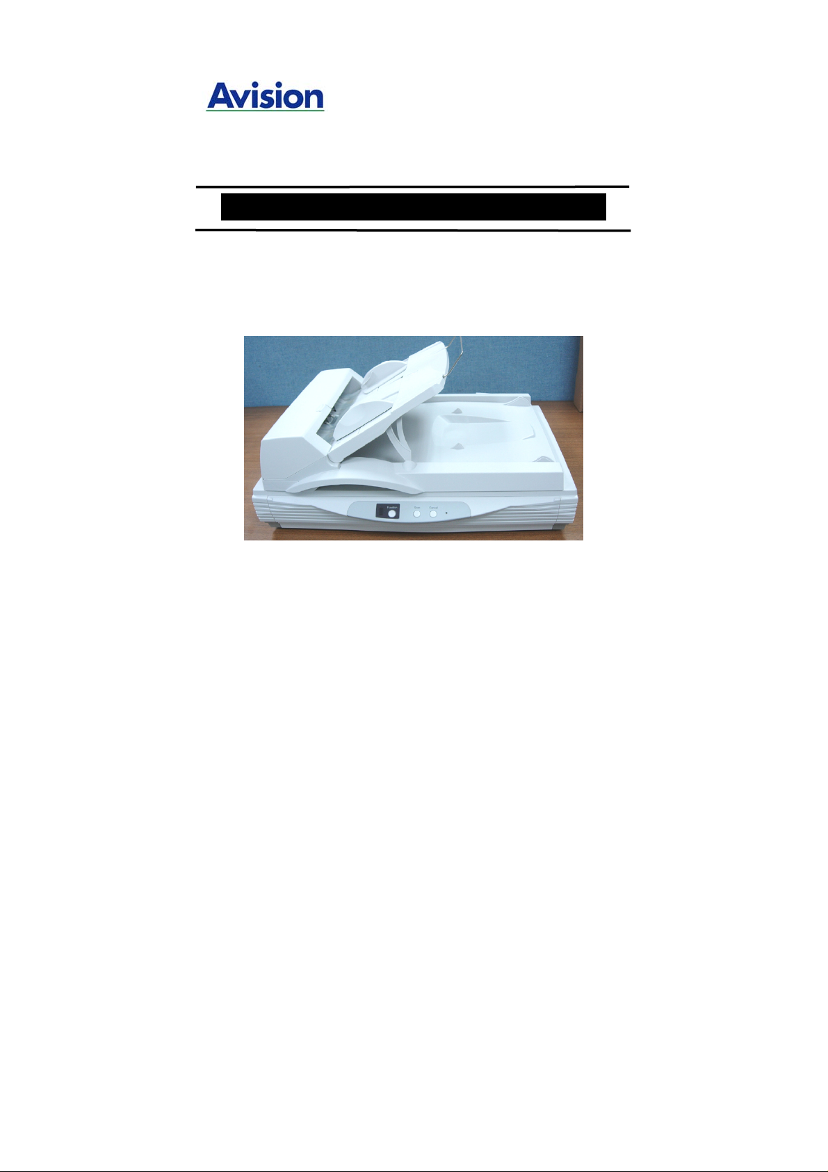
High Speed Document Scanner
User’s Manual
Regulatory model: DT-0603H
Page 2

Trademarks
Microsoft is a U.S. registered trademark of Microsoft
Corporation.
Windows and MS-DOS are trademarks of Microsoft
Corporation.
IBM, PC, AT, XT are registered trademarks of International
Business Machines Corp.
Other brands and product names herein are trademarks or
registered trademarks of their respective holders.
Copyright
All rights reserved. No part of this publication may be
reproduced, transmitted, transcribed, stored in a retrieval
system, or translated into any language or computer
language, in any form or by any means, electronic,
mechanical, magnetic, optical, chemical, manual, or
otherwise, without the prior written permission of Avision Inc.
Material scanned by this product may be protected by
governmental laws and other regulations, such as copyright
laws, the customer is solely responsible for complying with
all such laws and regulations.
Warranty
The information contained in this document is subject t o
change without notice.
2
Page 3

Avision makes no warranty of any kind with regard to this
material, including, but not limited to, th e implied warranties
of fitness for a particular purpose.
Avision shall not be liable for errors contained herein or for
incidental or consequential damages in connection with the
furnishing, performance, or use of this material.
3
Page 4

FCC Radio Frequency Interference Statement
This equipment has been tested and found to comply with
the limits for a class B digital device, pursuant to Part 15 of
the FCC rules. These limits are designed to provide
reasonable protection against harmful interference in a
residential installation. This equipment generates, uses, and
can radiate radio frequency energy and, if not installed and
used in accordance with the instruction manual, may cause
harmful interference to radio communication. However,
there is no guarantee that interference will not occur in a
particular installation. If this equipment does cause harmful
interference to radio or television reception, which can be
determined by turning the equipment off and on, the user
is encouraged to try to correct the interference by one or
more of the following measures:
− Reorient or relocate the receiving antenna.
− Increase the separation between the equipment and
receiver.
− Connect the equipment into an outlet on a circuit
different from that to which the receiver is connected.
− Consult the dealer or an experienced radio/TV technician
for help.
FCC CAUTION: To assure continued compliance,
(example - use only shield interface cables when connectin g
to computer or peripheral devices). Any changes or
modifications not expressly approved by the manufacture of
this device could void the user's authority to operate the
equipment. This device complies with Part 15 of the FCC
Rules. Operation is subject to the following two conditions:
(1) This device may not cause harmful interference, and (2)
this device must accept any interference received, including
interference that may cause undesired operation.
Responsible Party: Avision Labs, Inc.
Telephone No.: +1 (510) 739-2369
4
Page 5

5
Table of contents
1. INTRODUCTION.......................................................................7
2. SCANNER INSTALLATION..................................................9
2.1 PRECAUTIONS ......................................................................9
2.2 UNLOCKING YOUR SCANNER.............................................10
2.3 ADF PAPER CHUTE ...........................................................11
2.4 CONNECTING THE CABLES................................................13
2.5 INSTALLING THE SOFTWARE............................................. 13
2.6 CONNECTING TO COMPUTER.............................................14
3. COOMPLETING YOUR FIRST SCAN.............................16
3.1 PLACING YOUR ORIGINAL..................................................16
3.2 ADF SCANNING.............................................................17
3.3 SCANNING WITH IMAGE EDITING SOFTWARE.................18
4. USING THE SCANNER PROPERTIES DIALOG BOX
........................................................................................................21
4.1 BUTTONS ON THE SCANNER PROPERTIES DIALOG BOX.22
4.2 THE IMAGE TAB................................................................. 24
4.3 THE COMPRESSION TAB ...................................................35
4.4 THE COLOR DROPOUT TAB...............................................37
4.5 THE PAPER TAB .................................................................40
4.6 THE OPTIONS TAB.............................................................48
4.7 THE SETTING TAB .............................................................53
4.8 THE INFORMATION TAB ....................................................56
5. ISIS INTERFACE OPERATION .......................................58
6. USING THE BUTTON............................................................59
6.1 INSTALLING BUTTON MANAGER.......................................60
6.2 CHECKING THE BUTTON CONFIGURATIONS BEFORE
SCANNING..........................................................................61
6.3 THE DEFAULT BUTTON SETTINGS....................................63
Page 6

6
6.4 SCANNING FROM ONE TOUCH OF THE BUTTONS............64
6.5 PERFORMING CONTINUOUS SCAN FROM THE FLATBED..66
7. CARE AND MAINTENANCE...............................................69
7.1 CLEANING THE ADF..........................................................69
7.2 REPLACING THE ADF SNAP-IN PAD MODULE...................71
7.3 CLEANING THE GLASS.......................................................72
8. TROUBLESHOOTING...........................................................73
8.1 FREQUENTLY ASKED QUESTIONS .....................................73
8.2 TECHNICAL SERVICE .........................................................75
9. SPECIFICATIONS..................................................................76
Page 7

7
1. INTRODUCTION
Congratulations on your purchase of the Avision’s A3-sized
document scanner. Avision is one of the leading companies to
make high quality color image scanner.
To ensure the optimum performance of the scanner, please
take a few minutes to read through this manual before you
install and operate the new scanner. The manual contains
valuable information on how to unpack, install, operate,
and maintain the scanner properly.
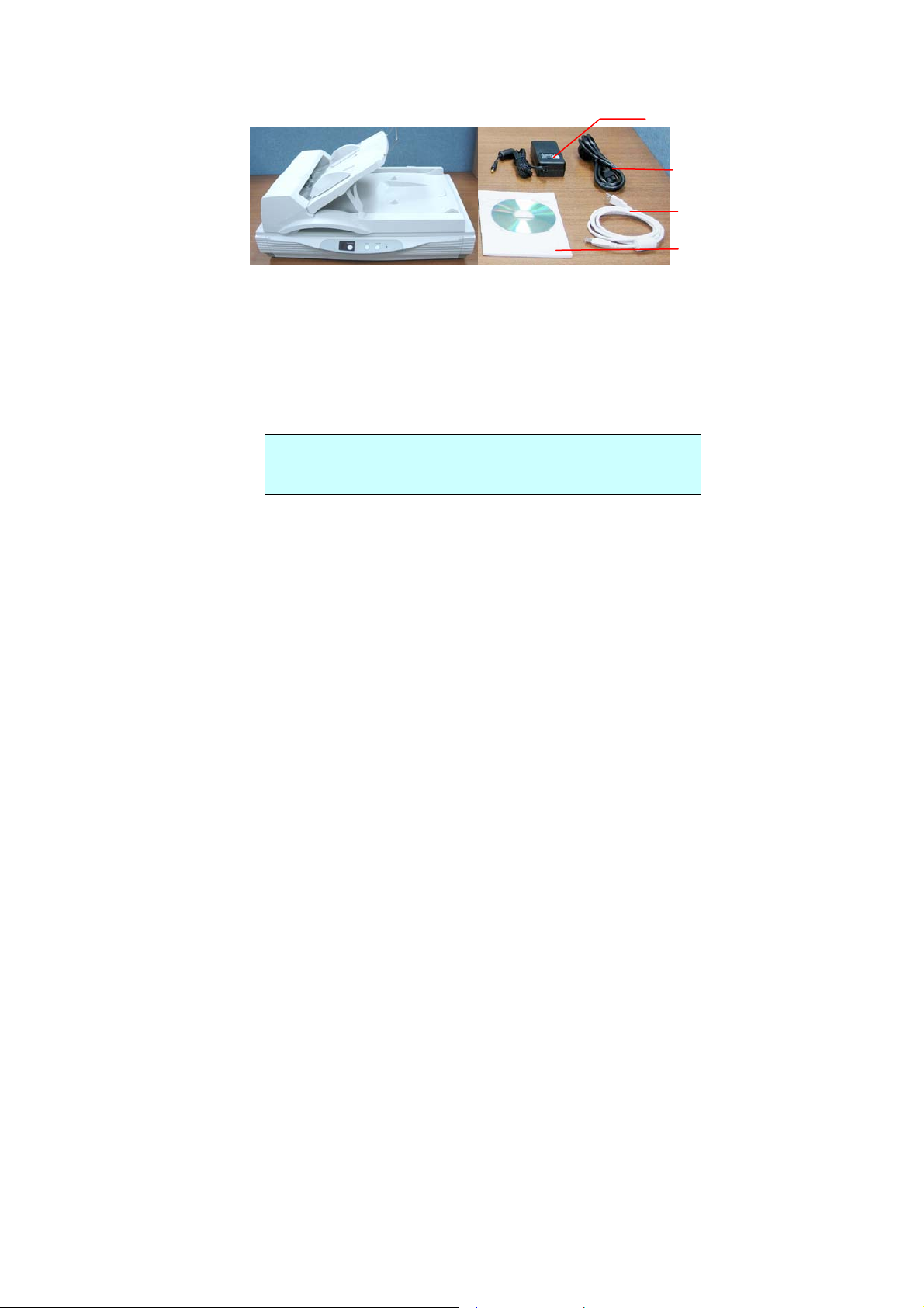
Figure 1-1 in below shows how the scanner is packed.
Please check if all items are included. If there is any item
missing or damaged, please contact your nearest dealer
immediately for replacement.
Page 8
8
2
3
1
1. Scanner main unit
2. Power adapter
3. Power cord
4. USB cable
5. User’s manual/CD
Figure 1-1 Scanner Packaging
Note: When you unpack the scanner, retain the
packing material and shipping box in case you may
transport the scanner in the future.
4
5
Page 9

2. SCANNER
INSTALLATION
2.1 PRECAUTIONS
¾ Keep the scanner out of direct sunlight. Direct
exposure to the sun or excessive heat may cause
damage to the unit.
¾ Do not install the scanner in a humid or dusty place.
¾ Be sure to use the proper AC power source (HEG42-
240200-7L made by HiTron).
¾ Place the scanner securely on an even, flat surface.
Tilted or uneven surfaces may cause mechanical
problems.
¾ Keep the shipping box and the material in case you may
need to ship the scanner again.
To run the scanner at rated speed as recommended, you
must have the following minimum requirements:
z IBM compatible Pentium III or later;
z Microsoft Windows 98se or later;
z One USB port installed on your computer;
z 20M bytes of available hard disk space for installation;
z 64M bytes of RAM ;
z A video graphics array (VGA 16.7 m.) monitor;
z A Microsoft Windows-compatible pointing device (e.g.,
the mouse);
z A CD-ROM drive.
9
Page 10
0
r
2.2 UNLOCKING YOUR SCANNER
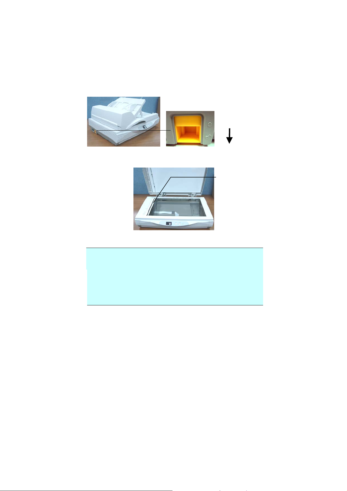
To protect the scanning unit from damage during
transportation, a lock switch is designed at the back of the
scanner to keep the scanning unit from moving. To unlock
the scanner, move the lock switch up as shown in Fig. 2-1.
Locked
Unlocked
Figure 2-1 Unlocking the Scanner
Scanning unit at
this position
before locking
the scanne
Figure 2-2 Home position
Note: If the scanning unit is not located at the front of the
scanner before transporting the scanner, be sure to do the
follows:
1. Turn on the scanner.
2. The scanning unit should move to the front of the
scanner.
3. Press the lock switch down to the “Lock position”.
4. The scanner is now ready to transport.
1
Page 11
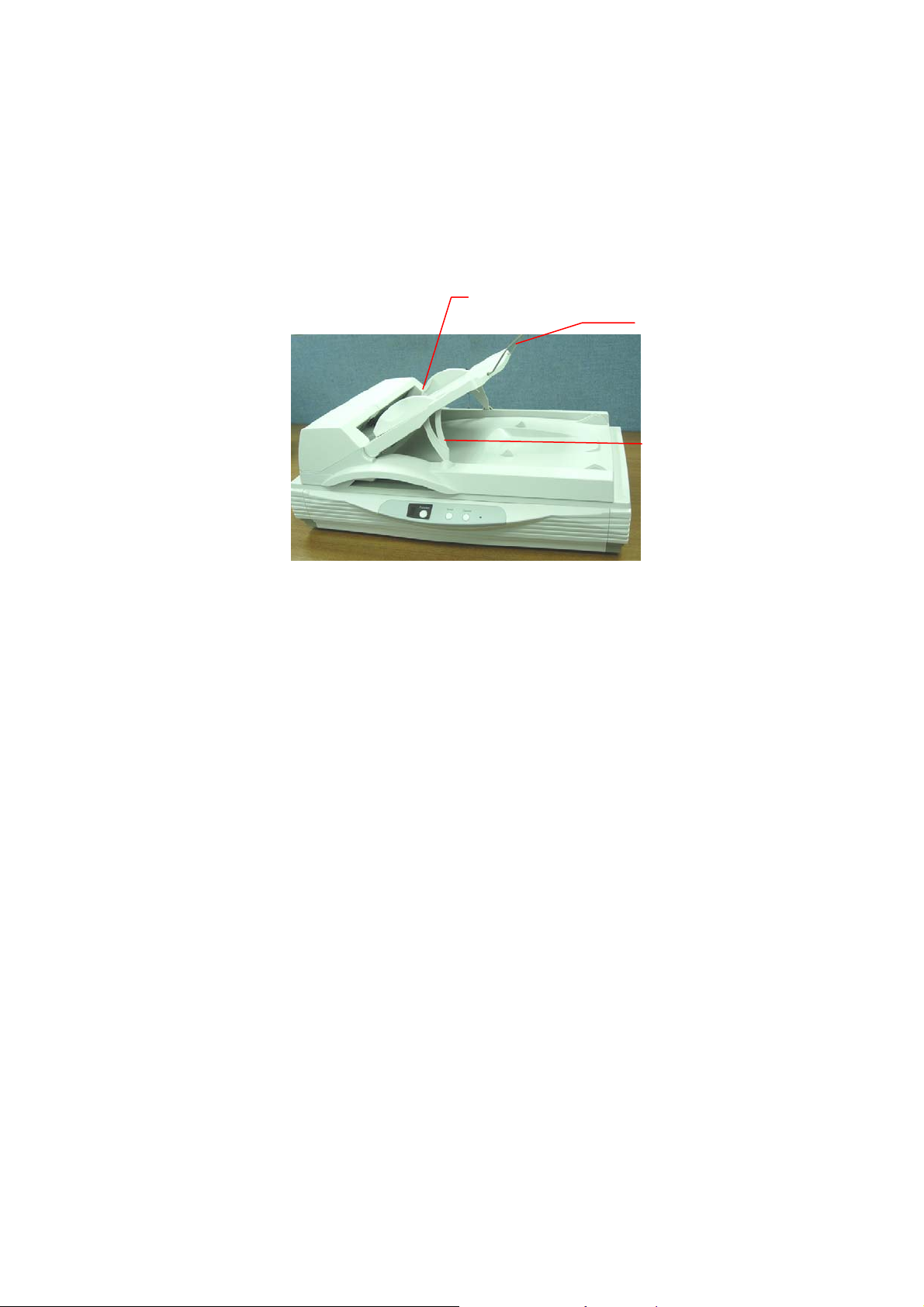
2.3 ADF PAPER CHUTE
A
i). Lift the paper chute to about 45 degrees.
ii). Pull the paper-chute wire leg down to the grips on
the document cover.
iii). Slightly press the paper chute to snap the wire leg
into the grips on the document cover.
iv). Pull out the paper chute extension to the length you
want.
DF Paper Chute
Paper
Chute
Extension
Paper
Chute
Wire
Legs
11
Page 12
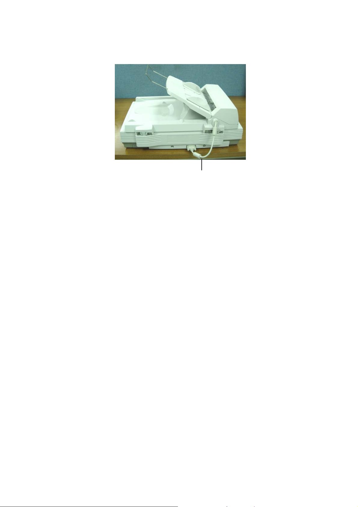
ADF Cable
12
Page 13
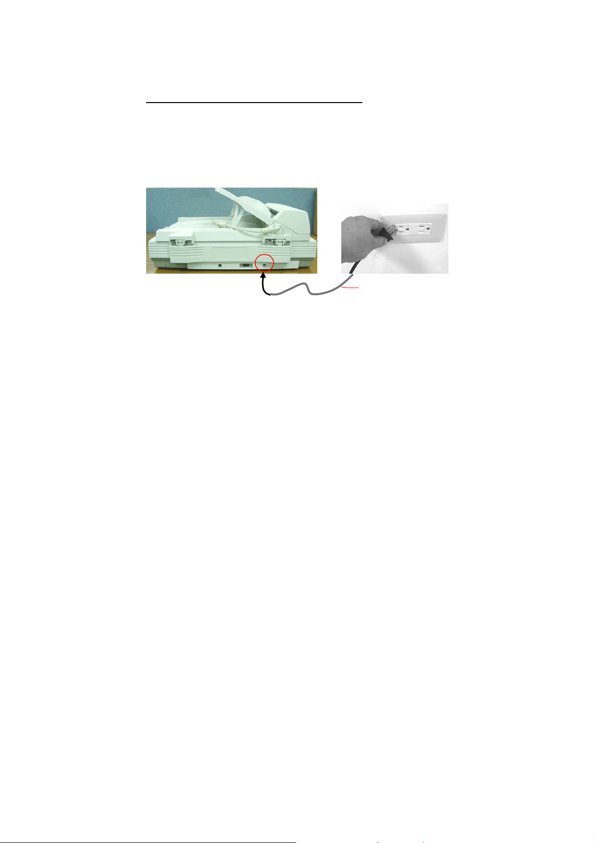
2.4 CONNECTING THE CABLES
Make sure the power of scanner is off.
2.4.1 CONNECTING TO POWER
Plug the small end of the power adaptor into the power jack
of your scanner. Insert the other end to an appropriate
power outlet.
Power Cable
2.5 INSTALLING THE SOFTWARE
NOTE:
1). The Windows system CD may be required when
installing on some PC’s.
2). To ensure your computer can identify the USB
scanner, please install scanner driver first before
connecting the scanner to your computer.
1. Place the supplied CD-ROM onto your CD-ROM drive.
2. The software installation graphic appears. If not, run
“cdsetup.exe”.
13
Page 14
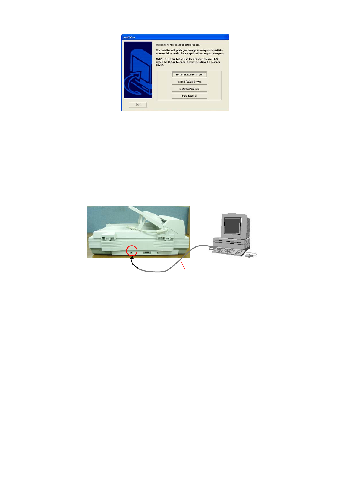
3. Choose Install TWAIN Driver to install the scanner
driver.
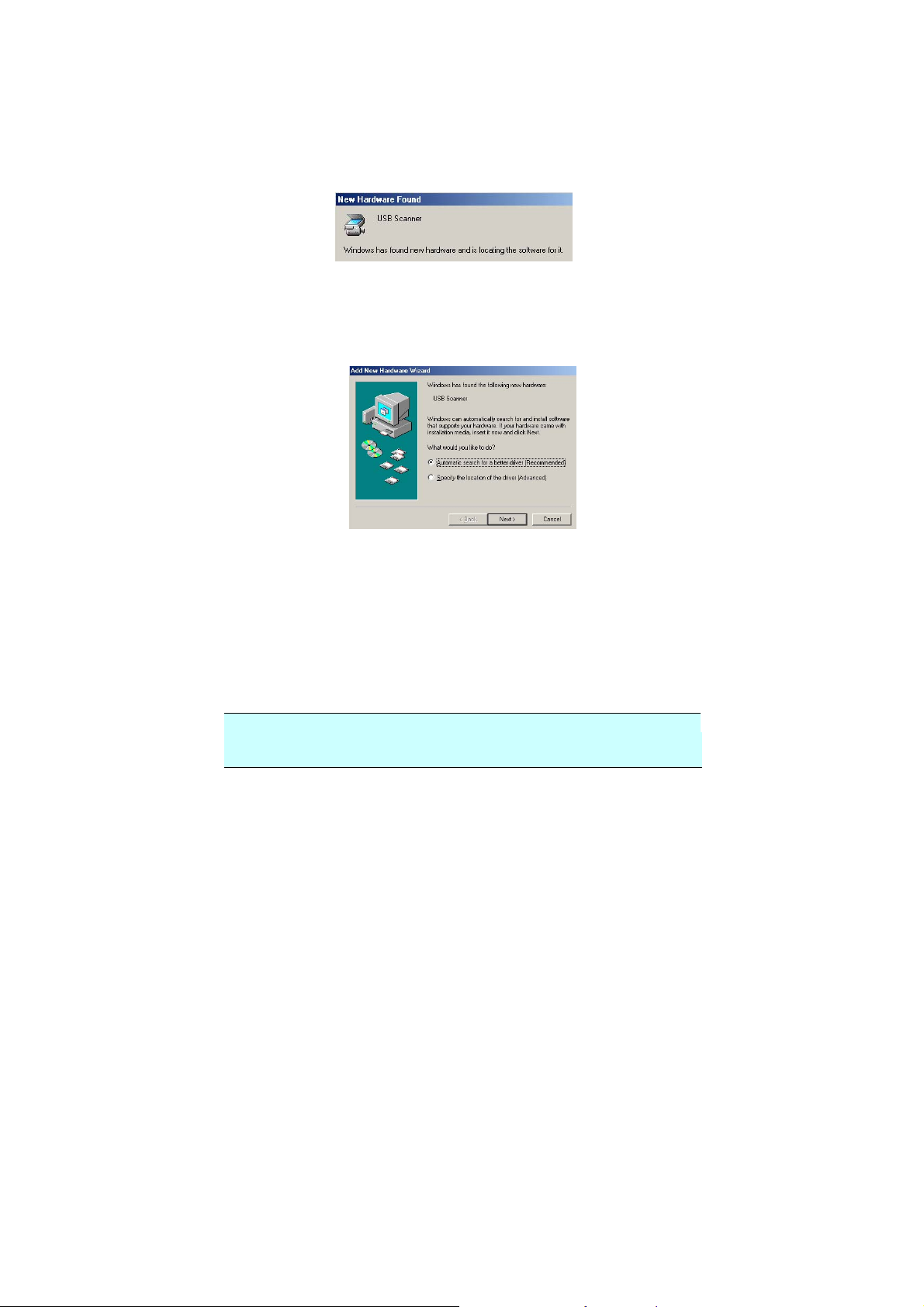
2.6 CONNECTING TO COMPUTER
1. Connect the square end of the USB cable to the USB port
of your scanner. Connect the rectangle end to the USB
port of your computer.
USB cable
14
Page 15
5
2. The computer should detect a new USB device and
prompt a “New Hardware Found” message.
(Windows 9X/Windows ME)
3. In Windows 9X or Windows ME, confirm that the
“Search for a better driver.” is selected and click the
“Next” button.
In Windows XP, click the Next button to continue.
When the XP certification screen appears, click
Continue Anyway to complete the installation.
4. When the Finish dialog is prompted, click the Finish
button.
5. Click “View Manual” to view or print the detailed user
manual for the scanner and bundled applications
respectively.
Note:
To uninstall the scanner driver in Windows XP, be sure to keep
your scanner connecting to your computer.
1
Page 16
3. COOMPLETING YOUR
FIRST SCAN
3.1 PLACING YOUR ORIGINAL
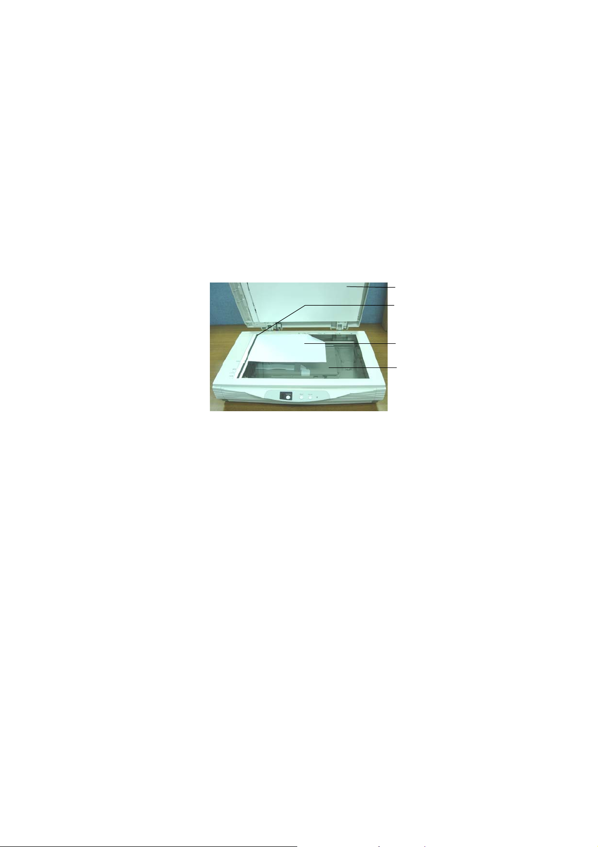
Open the document cover then place your original face
down on the document glass as shown in Fig. 3-1.
Make sure the top of your original near the document
alignment mark.
1
2
3
4
1. Document cover
2. Document alignment mark
3. Your original
4. Document glass
Figure 3-1 Placing the original
16
Page 17
3.2 ADF SCANNING
aced
ocument
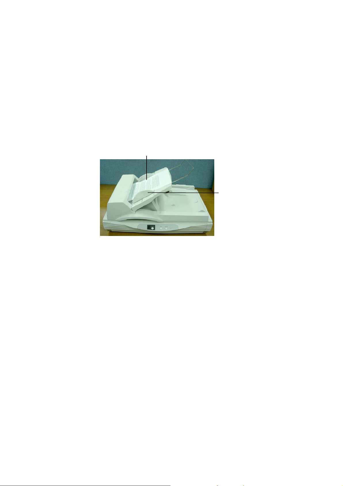
Multiple documents can be fed automatically using the ADF.
i). To prevent occasional paper jam when automatically
feeding multiple documents, fan the paper before
loading.
ii). Place the documents face-up onto the ADF paper
chute, with the leading edge in the auto feeder
entrance.
iii). Adjust the left and right guides so that they are snug
against the sides of the documents.
F
-up D
Guide
17
Page 18
3.3 SCANNING WITH IMAGE EDITING SOFTWARE
The scanner driver is not a stand-alone program, it has to
be started from within a TWAIN-compliant or plug-in
software application and then the scanner driver is able to
scan and load the image to your computer. The command
to start the scanner driver may vary due to different
software applications.
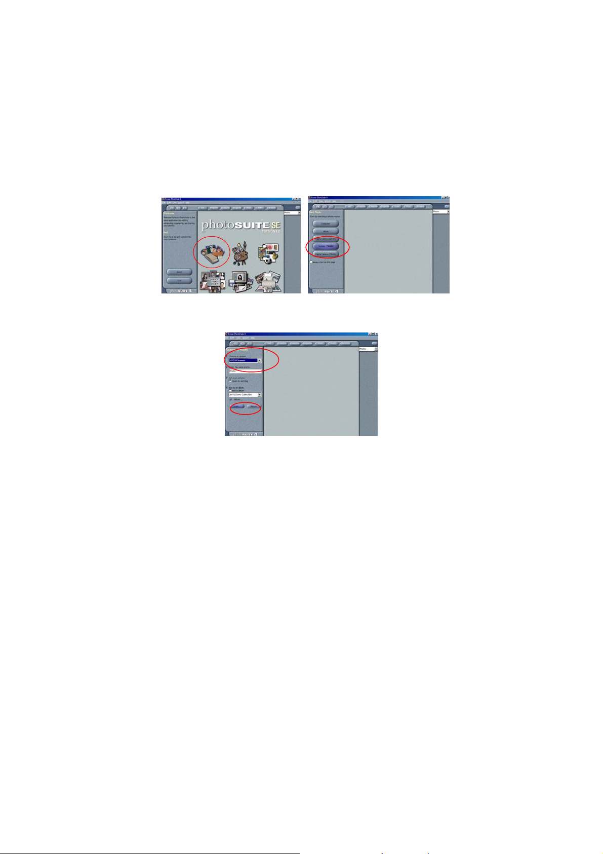
1. Start a TWAIN compliant software application such as
Roxio PhotoSuite which is bundled in the CD.
2. Click Get>Scanner (TWAIN).
3. Choose the scanner model as your scanning source.
(You only need to do this once.)
4. Place the document FACE DOWN on the document
glass.
5. Click the Scan button to prompt the Scanner Properties
Dialog Box.
6. Choose your image type and the side of document you
wish to scan from the Image Selection box. Click the
Scan button to scan the document.
18
Page 19
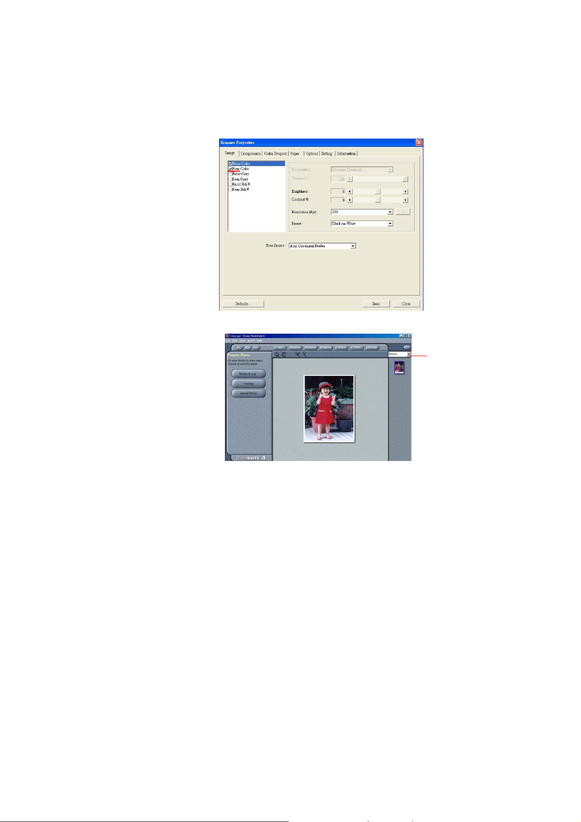
7. Click Exit to return to the main screen and click
Open Library and Photos at the upper-right corner
to open your scanned image.
Image
Selection Box
Photos
19
Page 20
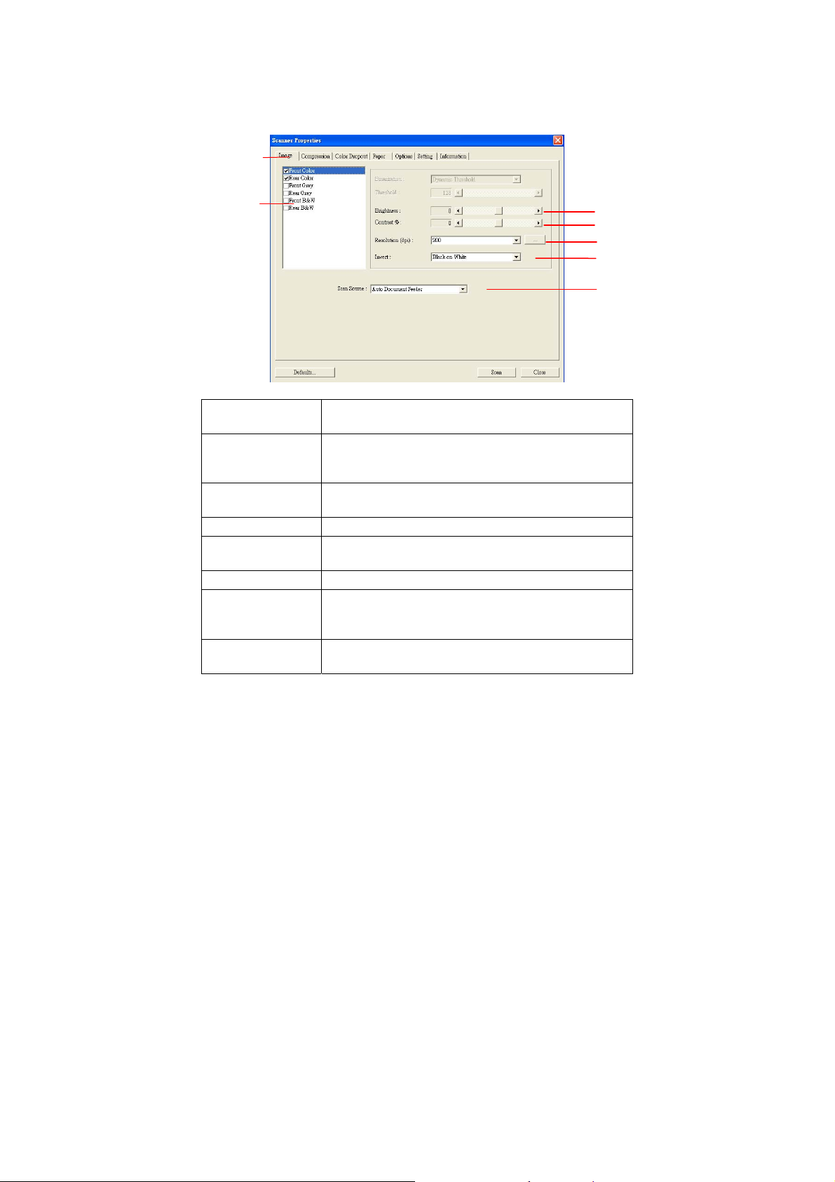
3.3.1 A GLANCE OF THE SCANNER PROPERTIES
DIALOG BOX
1
2
3
4
5
6
7
1. Tab Options Choice: Image, Compression, Color Dropout,
Paper, Options, Settings, Information.
2. Image
Selection
Box
3. Brightness: Adjust the brightness level from –100 to
4. Contrast Adjust the contrast level from –100 to +100.
5. Resolution
6. Invert Reverse the color of your scanned image.
7. Scan Source Choice: Auto Document Feeder, Flatbed,
8. Defaults Reset all values on the tabs to the factory
Choose your image type and the side of
document you wish to scan. Options vary
based on type of scanner.
+100.
Determine the quality of the scanned image.
The industry standard is 200 dpi.
Flatbed (Book), Automatic (This option varies
based on type of scanner.)
default settings.
20
Page 21
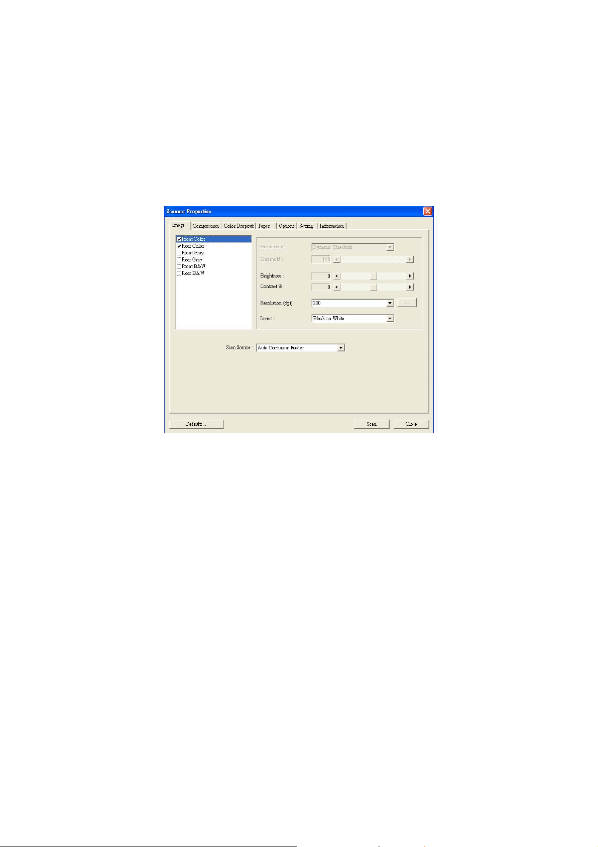
4. USING THE SCANNER
PROPERTIES DIALOG
BOX
The Scanner Properties dialog box allows you to configure
the scanner’s settings. It consists of several tabbed
windows each of which will be described in this chapter.
The Scanner Properties dialog box
21
Page 22
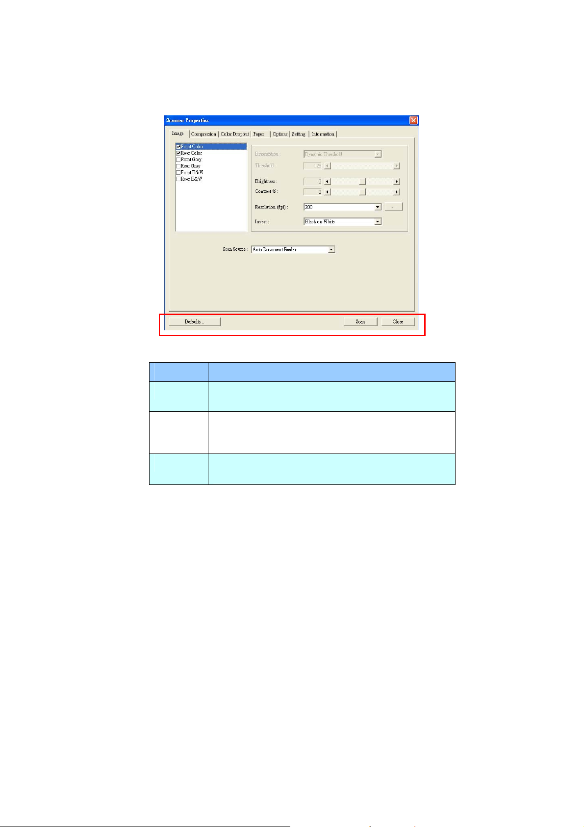
4.1 BUTTONS ON THE SCANNER PROPERTIES
DIALOG BOX
The buttons on the Scanner Properties dialog box
Buttons
Description
Defaults Click the Defaults button, the factory default
settings will be shown on each tab.
Scan After all the scan settings are satisfactory, click
the Scan button to start scanning your
document.
Close Click the Close button to leave the Scanner
Properties dialog box.
22
Page 23

The following table shows the default settings:
Tab name Default settings
Image Image:Front B&W
Binarization:Dynamic Threshold
Resolution:200 dpi
Invert:Blank on White
Scan Source:Auto Document Feeder
Threshold:None
Brightness:None
Contrast:None
Compression None
Color Dropout None
Paper Cropping:Automatic
Deskew:Yes
Orientation:Portrait
OverScan:0.00
Multifeed Detection:None
Unit:Inch
Options Flip Side Rotation: Book
Rotation Degrees:None
Blank Page Removal:None
Edge Fill:White,0 mm
Image Control Option:None
Setting Enable Energy Saver:Enable, 15
minutes after last scan action
Show Scanning Progress:Yes
Show Warning Message:Yes
Save Settings after Closing:Yes
23
Page 24
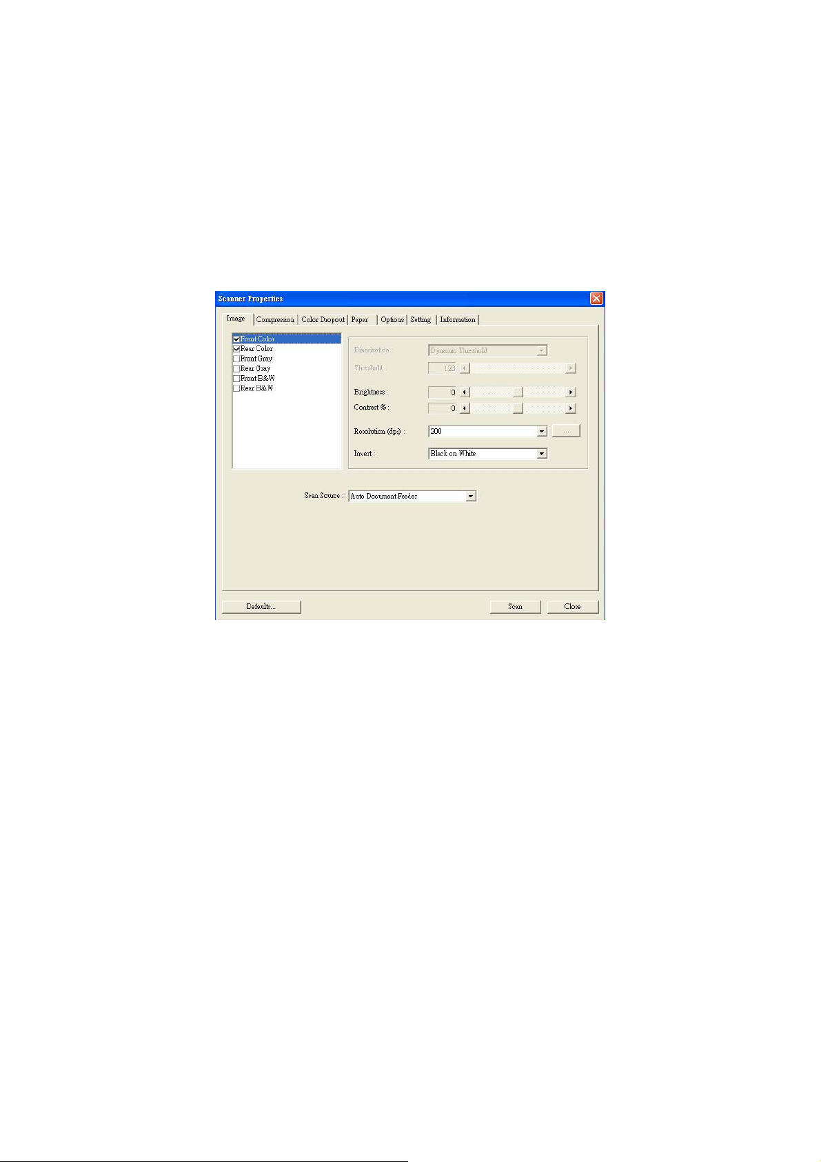
4.2 THE IMAGE TAB
The Image tab allows you to choose the front side and (or)
the rear side of your document, the type of image, and to
set several basic scan settings. Note that except for the
resolution, you can set individual scan settings for the front
side and the rear side. For example, all settings in the
Image tab, Compression tab, Color Dropout tab can be set
individually for the front and the rear side. However, the
settings in the Paper tab, the Option tab, and the Setting
tab have to be set the same for the front and rear side.
The Image tab dialog box
24
Page 25
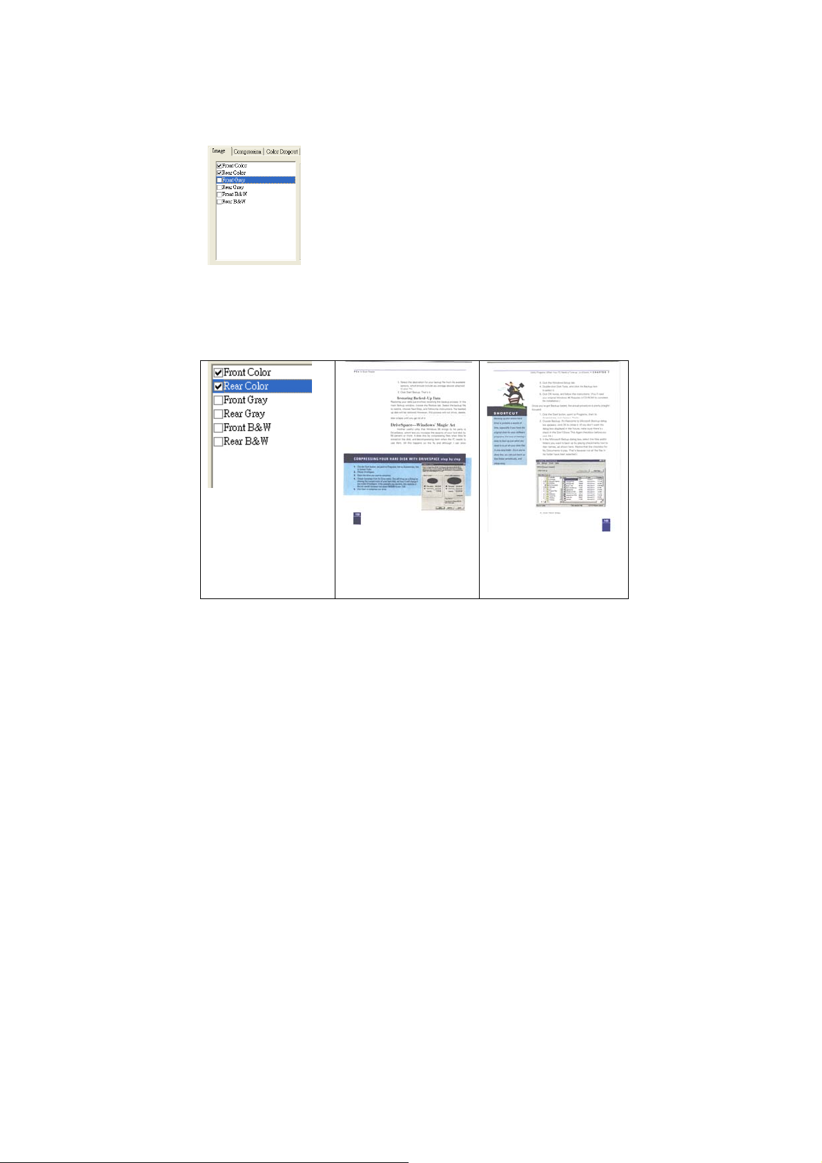
4.2.1 THE IMAGE SELECTION BOX
The Image Selection box includes the
image type and document side option.
If you wish to scan both the front side
and the rear side of your color
document, you can check both Front
Color and Rear Color at the same time.
Note the options vary based on type of
scanner.
Example 1:Scanning a two-sided color document,
both sides in color
Side/Image
Selection
Front
25
Rear
Page 26
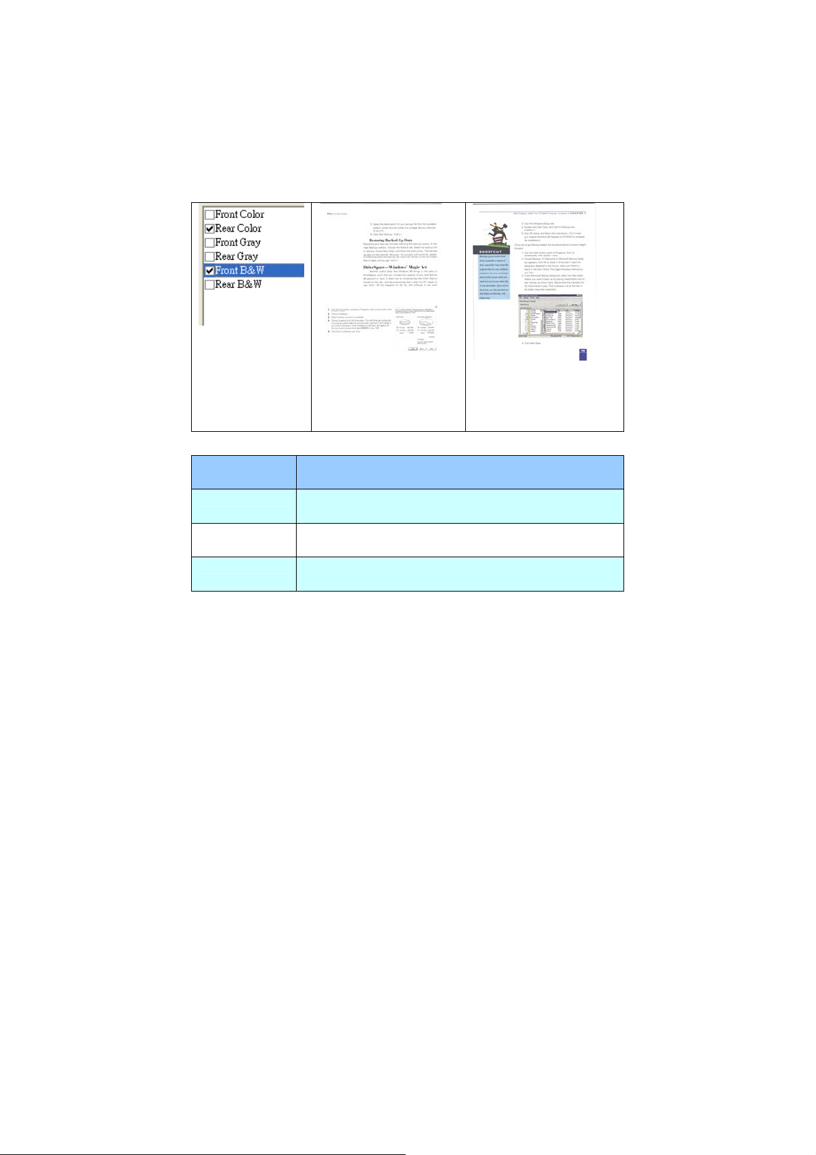
Example 2:Scanning a two-sided color document,
one in B&W(Drop Blue Color:Threshold:10,
Background:79), the other in color
Side/Image
Selection
Front
Rear
Image
Description
Type
Color Choose Color if you wish to scan a color
image for your original in color.
Gray Choose Gray image if your original contains
actual shades of gray.
B&W Choose B&W if your original contains only
text, pencil or ink sketch.
26
Page 27

B&W Gray Color
27
Page 28

4.2.2 OTHER IMAGE OPTIONS
Binarization This is the process of converting a
grayscale or color image to a bi-tonal
image. There are several different
methods of performing this conversion.
Two of the options are Dynamic
Threshold and Fixed Processing.
Dynamic Threshold: Selecting Dynamic
Threshold allows the scanner to
dynamically evaluate each document to
determine the optimal threshold value to
produce the highest quality image. This is
used to scan mixed document containing
faint text, shaded background, or color
background with a single setting. If
Dynamic Threshold is selected, Threshold,
Brightness, and Contrast are not available.
Fixed Processing: Used for black-andwhite and other high contrast documents.
A single level is set to determine the
black-and-white transition. The threshold
is programmable over the entire density
range. Fixed Processing sets Contrast
to 0. If Fixed Processing is selected,
Contrast is not available.
28
Page 29
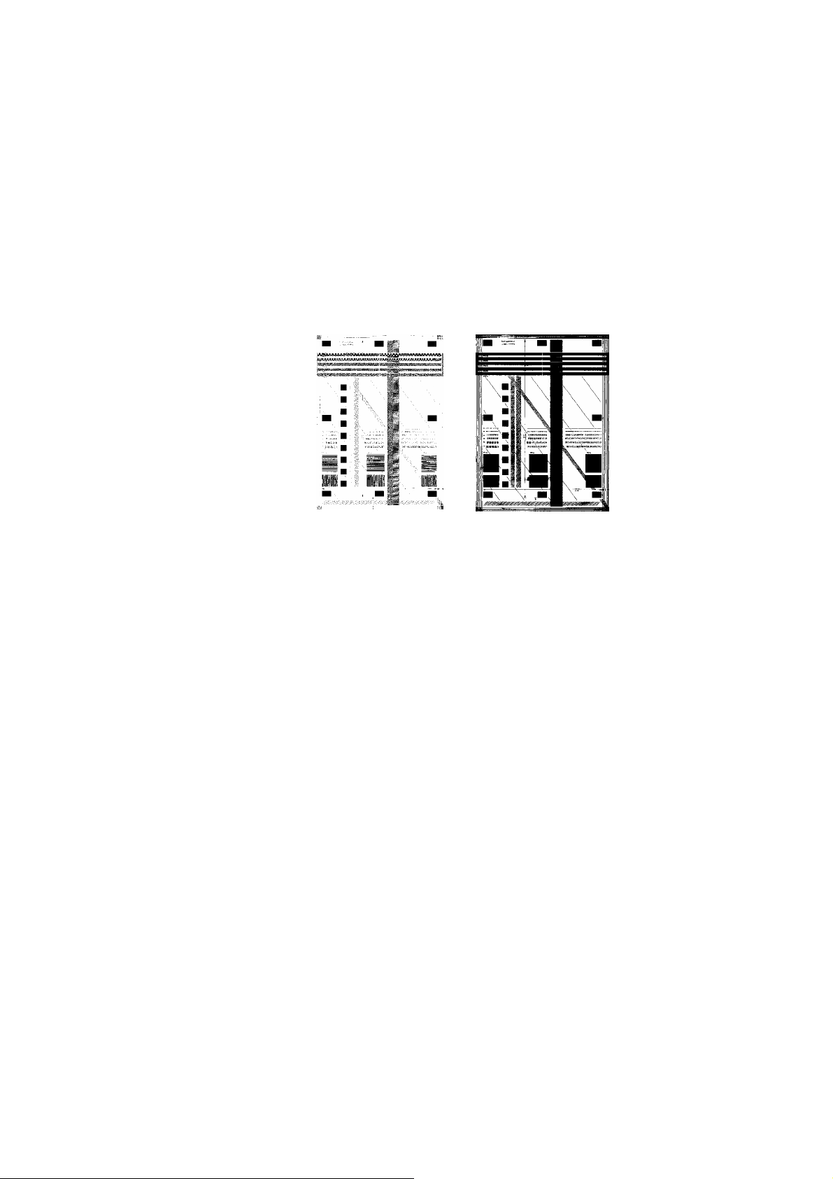
Threshold Used to convert a grayscale image to a
bi-tonal image. The value ranges from 0 to
255. A low threshold value produces a
lighter image, and can be used to subdue
backgrounds and subtle, unneeded
information. A high threshold value produces
a darker image, and can be used to help pick
up faint images.
Adjust the threshold setting by dragging the
Threshold sliding bar to the left or right to
achieve the desired threshold setting.
200 dpi,
Threshold:80,
Brightness: 0
200 dpi,
Threshold:170,
Brightness: 0
29
Page 30
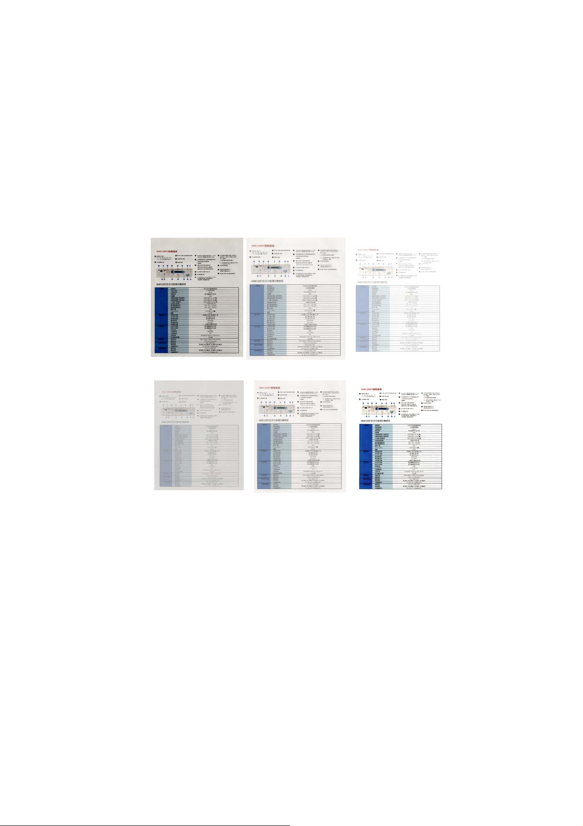
Brightness
Contrast
Adjusts the lightness or darkness of an
image. The higher the value, the
brighter the image. Drag the slider to
the right or left to increase or decrease
the brightness.
+100.
The range is from –100 to
Adjusts the range between the darkest
and the lightest shades in the image.
The higher the contrast, the bigger the
different grayscale. Drag the slider to the
right or left to increase or decrease the
contrast.
+100.
The range is from –100 to
Brightness: -50 Brightness: 0
(Normal)
Contrast: -50 Contrast: 0
(Normal)
30
Brightness: +50
Contrast: +50
Page 31

Resolution
A good control of the resolution results a
good detail of an image that scans. The
resolution is measured by dots per inch
(dpi). Normally, the greater the dpi
number, the higher the resolution and
the image file size. Be aware that
greater resolution takes more time to
scan, and more disk space for the
scanning image. For your information,
an A4 size color image scanned at 300
dpi at True Color mode consumes
approximately 25 MB of disk space. A
higher resolution (usually means over
600 dpi) is only recommended when you
need to scan a small area at True Color
mode.
Choose a resolution value from the drop
down list. The default value is 200 dpi.
Available resolutions are 75, 100, 150,
200,300, 400 and 600. Or you may
choose your desired value by clicking the
box in the right side of the drop down
list and press the arrow key to select
your desired value and then click the
Add button to include it in the drop down
list.
Resolution: 75 dpi
Resolution: 150 dpi
31
Page 32
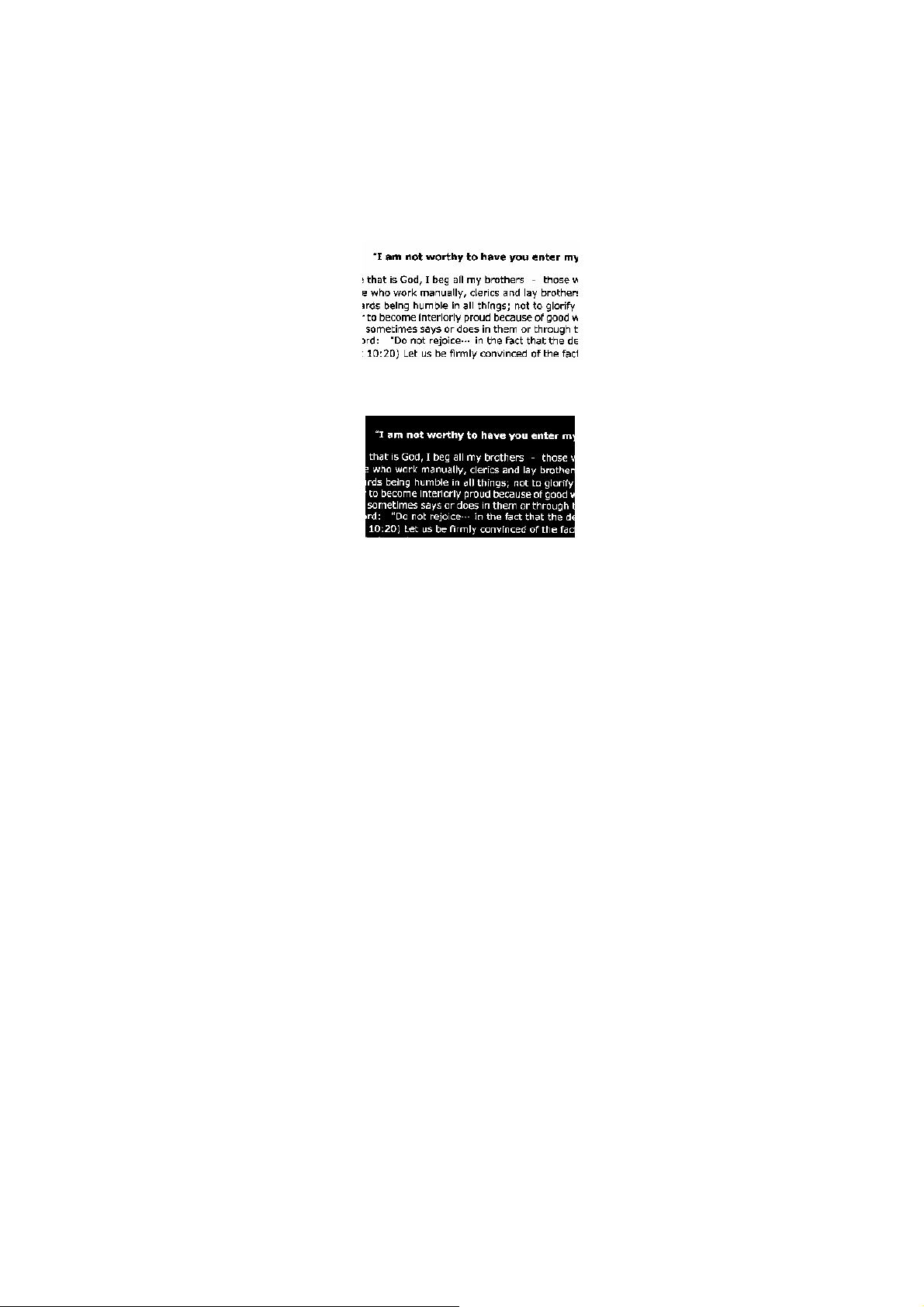
Invert Reverses the brightness and the colors in the
image. The default setting is Black on a White
background. Reverse mode is White on a Black
background. For color images, each pixel will be
changed into its complementary color at the
command of Invert.
Black on White
White on Black
32
Page 33

Scan
Source
Choice:
Auto Document Feeder: Used to scan multiple
pages.
Flatbed: Used to scan a single page. For
example, pages from newspaper clipping, paper
with wrinkles or curls.
Flatbed (book): Used to scan several inside
pages from book.
Automatic: Allow the scanner automatically set
its scan source. If Automatic is selected and
there is document in both the auto document
feeder (ADF) and the flatbed, then the scan
source will be automatically set to ADF. If
Automatic is selected and there is document
only in flatbed, then the scan source will be set to
flatbed.
Note the options vary based on type of scanner.
4.2.3 SCANNING COLOR IMAGES
The following options are available for scanning color
images.
y Brightness
y Contrast
y Resolution
y Invert
33
Page 34

4.2.4 SCANNING GRAYSCALE IMAGES
The following options are available for scanning gray
images.
y Brightness
y Contrast
y Resolution
y Invert
4.2.5 SCANNING B&W IMAGES
The following options are available for scanning B&W
images.
y Binarization (Dynamic Threshold)
y Resolution
y Invert
Or
y Binarization (Fix Processing)
y Threshold
y Brightness
y Resolution
y Invert
34
Page 35

4.3 THE COMPRESSION TAB
The Compression tab allows you to compress your scanned
image and choose the level of compression. Bi-tonal
images are normally compressed using CCITT standard
called Group 4 (G4). Color and grayscale images are often
compressed using JPEG technology. Move the JPEG
Quality slider to the right or left to increase or decrease
the level of compression. Note the greater the compression
level, the lower image quality. Default is 50%.
Note that the compression depends on your image editing
application. If your image editing application does not
support the type of compression format, then either a
warning message will appear or the image quality of the
compressed file will not be acceptable.
JPEG (Joint Photographic Editor Group). This group
developed and lent their name to a file compression
standard for color and grayscale images that is widely used
by scanners, and software applications. On Microsoft
Windows-based systems, a file with the extension .jpg has
normally been compressed using this standard.
For scanning color or gray images, the following
compressions are available:
y None
y JPEG
For scanning B&W images, the following compressions are
available:
y None
y G4
35
Page 36
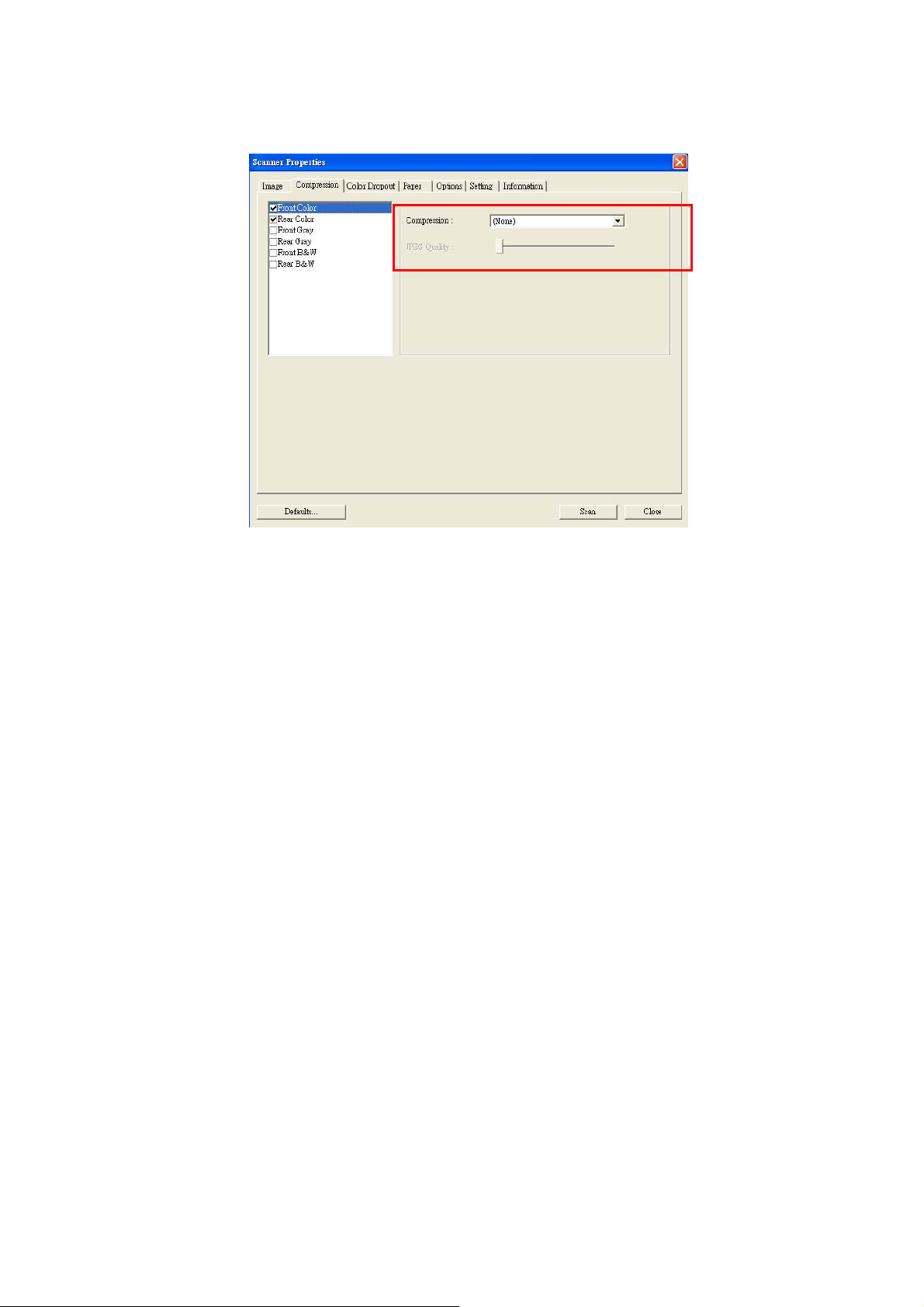
The Compression tab dialog box
36
Page 37
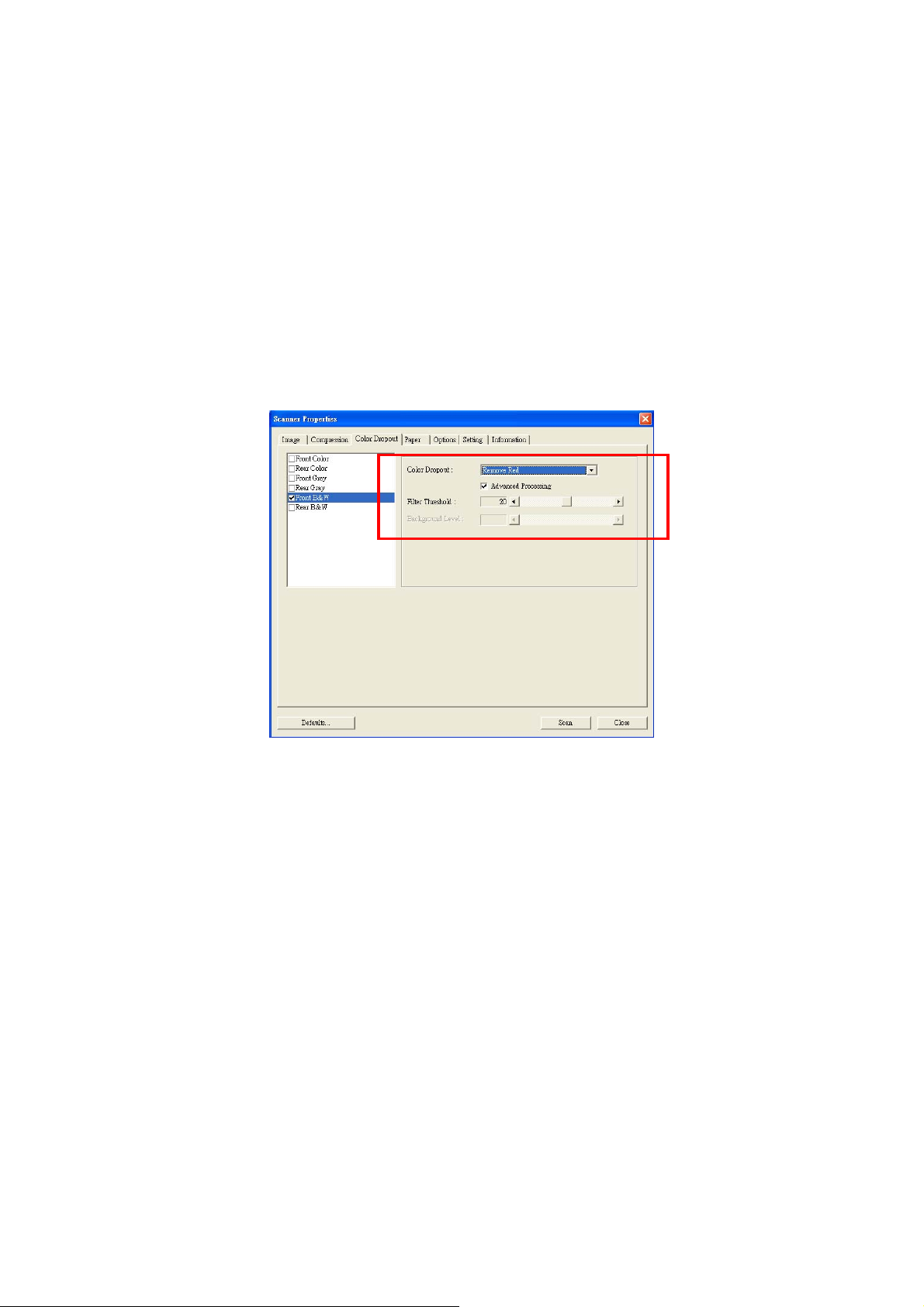
4.4 THE COLOR DROPOUT TAB
4.4.1 COLOR DROPOUT SELECTION
Color Dropout tab allows you to drop either of the red, blue,
or green color in your scanned image. If your image
contains red color watermark or background, choose the R
(Red) channel then any red watermark or background will
be removed. This feature is used to sharpen your text
when using OCR (Optical Character Recognition) software.
Note that this function supports only black & white and gray
images. Therefore, be sure to choose any black & white or
gray image type while applying this function.
The Color Dropout dialog box
37
Page 38
4.4.2 OTHER COLOR DROPOUT OPTIONS
Advanced Processing provides two options that can
adjust your scanned image in the best optimal result.
Filter
Threshold
This value is used to determine the color
which will be dropped out. A lower value
will drop more of the selected color out,
while a higher value will leave more of the
selected color in.
Background
Level
The pixel which is higher than the
background value will be adjusted to the
lightest point. Adjust the value for both the
Filter Threshold and Background Level to
produce the best optimal result.
Example, slightly adjusting the background value
makes your text more clear.
Original
38
Page 39
Remove Blue, Threshold: 20, Background:
255
Remove Blue, Threshold: 20,
Background Level: 210
39
Page 40
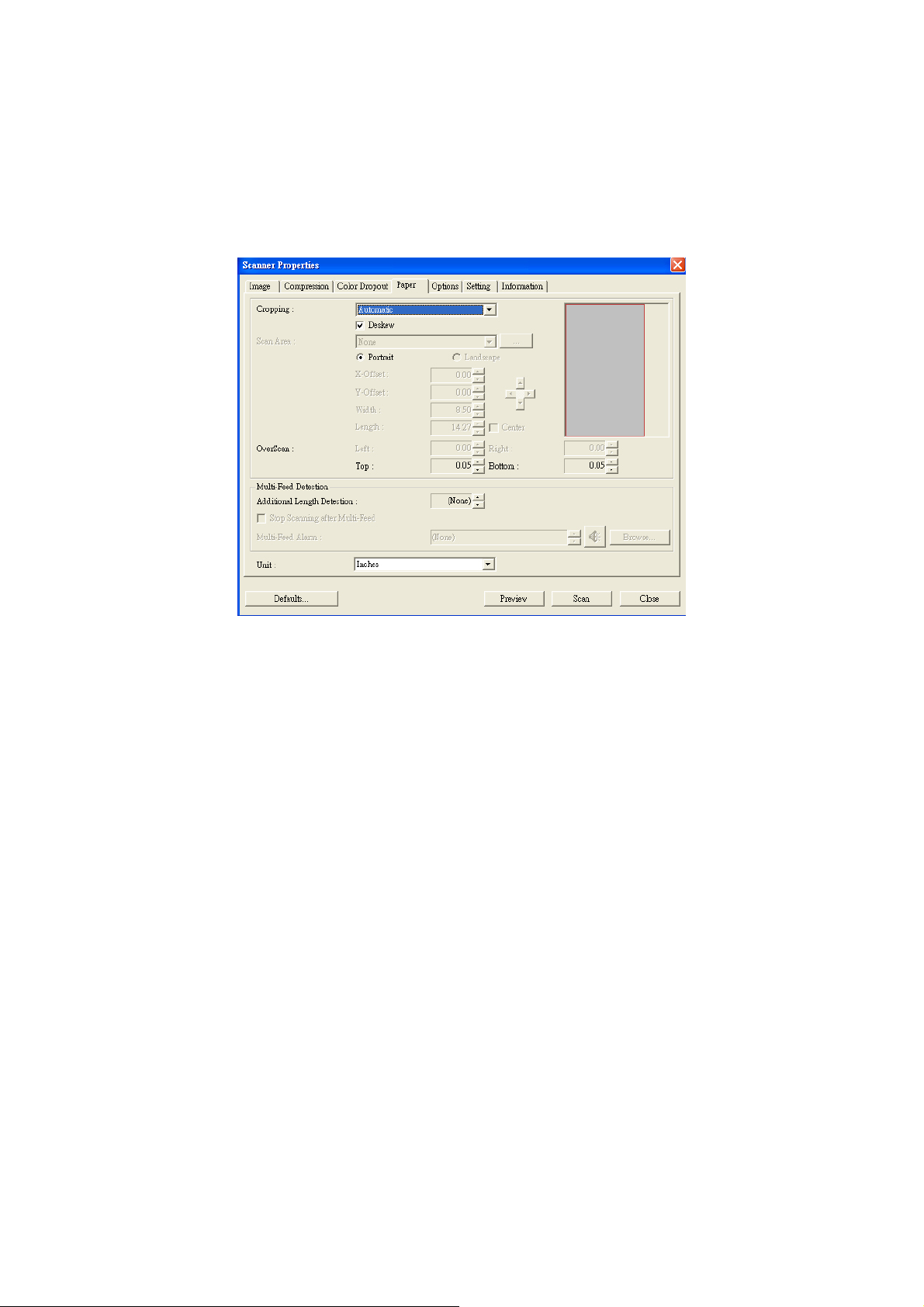
4.5 THE PAPER TAB
The Paper tab allows you to define values relating to image
output (i.e., Auto Crop or not, Scan Area, OverScan, MultiFeed Detection).
The Paper tab dialog box
40
Page 41

4.5.1 CROPPING
Cropping allows you to capture a portion of the
document being scanned. Choice: Automatic,
Fixed to Transport, EOP (End of Page) Detection.
Options Description
Automatic Automatic adjusts the cropping window
according to different document sizes. Use
this option for batches of mixed-sized
documents.
Fixed to
Transport
EOP (End of
Page)
Detection
This feature allows you to define the area
or zone to be imaged. Use for batches of
same-sized documents. If you select this
option, you can use the arrow keys to
define the x and y offset values, width and
length to redefine your scanned area. The
Display window will show image placement
as you change the values.
This feature allows you to define the area
or zone to be imaged. Use for batches of
same-width but different length
documents. If you select this option, you
can use the arrow keys to define the x and
y offset values, width and length to
redefine your scanned area. The Display
window will show image placement as you
change the values.
41
Page 42

The following options are only available when Fixed to
Transport is selected.
y X-Offset — the distance from the left end of the
scanner to the left edge of the scanning area.
y Y-Offset — the position from the top end of the
document to the top end of the scanning area.
y Width — the width of the scanning area.
y Length — the length of the scanning area.
y Center: automatically calculates the x-offset for
center-fed feeding based upon document size selected.
y — relocate the scan area by click the arrow key
on the cross sign while retain the scan size. View the
result from the Display window.
42
Page 43
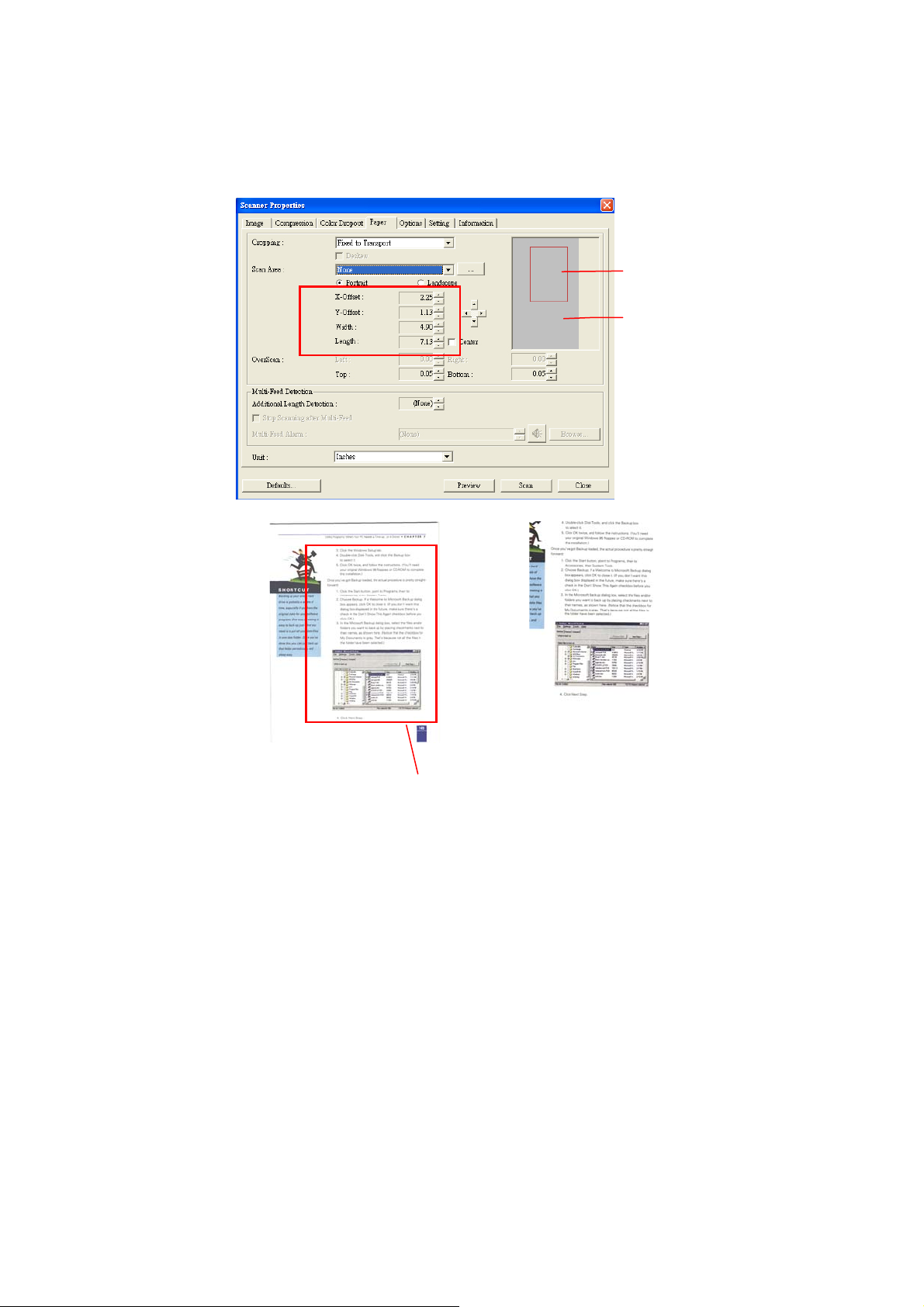
A
T
Example: Redefine your scan area ( x-offset: 2.25
inches;y-offset:1.13 inches)
Scan
rea
Display
window
After Fixed to
Original
he Redefined Scan Area
Transport
43
Page 44

4.5.2 OTHER PAPER SELECTION
Deskew
Use this option to automatically deskew a document.
Note: If the skew angle is
too great, some of the
image may be cut off.
Scan Area
Choose your desired paper size with the drop-down list box.
Or you may select a custom paper size by clicking the Scan
Area box and then click Add to include in the choice.
Choice: None, US Letter- 8.5”x 11”, US Lega – 8.5” x 14”,
ISO A4 – 21 x 29.7 cm, ISO A5 – 14.8 x 21 cm, ISO A6 –
10.5 x 14.8cm, ISO A7 – 7.4 x 10/5 cm, ISO B5 – 17.6 x
25 cm, ISO B6 – 12.5 x 17.6 cm, ISO B7 – 8.8 x 12.5 cm,
JIS B5 – 18.2 x 25.7 cm, JIS B6 – 12.8 x 18.2 cm, JIS B7 –
9.1 x 12.8 cm, Scanner Maximum.
OverScan
Overscan allows you to add a specific margin at top and
bottom or right and left (Options vary based on the type of
scanner) of the edge of the image. This is used to reduce
possible corner clipping on the skewed images and often
applied to a batch of skewed document to be scanned in
the auto document feeder. Select a value between 0 and
+5 mm. Note the overscan result will not be shown in the
Display window and that the availability of the function
varies based on type of scanner.
44
Page 45

Multi-Feed Detection
Multi-Feed Detection allows you to detect overlapped
document that go through the auto document feeder.
Multi-Feed usually occurs due to stapled documents,
adhesives on documents, or electro-statically charged
document. Note: The availability of the function varies
based on type of scanner.
Additional Length Detection
Additional Length Detection allows you to define the length
of document being multi-fed. This value indicates t he
additional length exceeding your scan area. The Display
window will show the size of the document as you ch ange
the value. A value of 0 indicates no additional length
detection. The Additional Length Detection is best used
when scanning same-size documents in the auto document
feeder.
45
Page 46
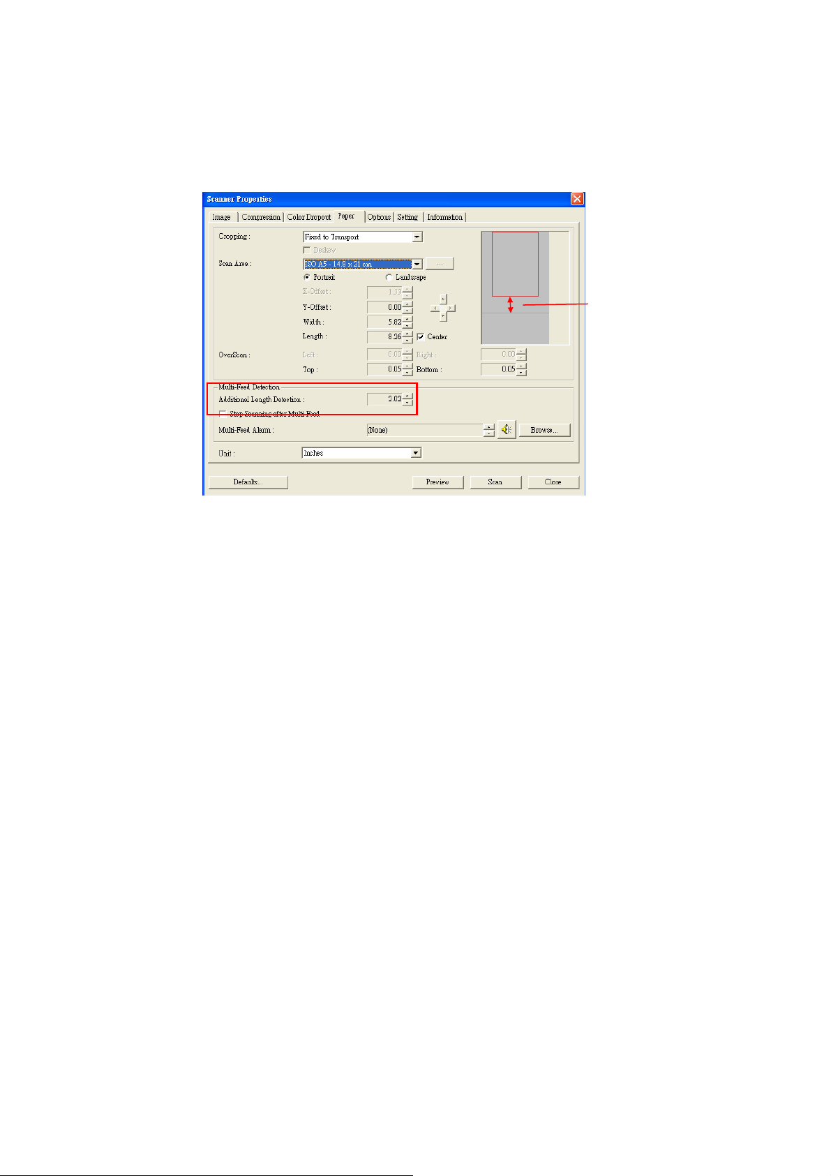
Example:Additional Length Detection:Set
Additional Length to be 2.02 inches
2.02”
There are two options available if Multi-Feed is detected.
z Stop Scanning after Multi-Feed
If this is selected, the scanner will stop the feeder if
multi-feed is detected.
z Multi-Feed Alarm:
If this is selected and a wave file is added, the scanner
will produce a sound alarm if multi-feed is detected.
46
Page 47
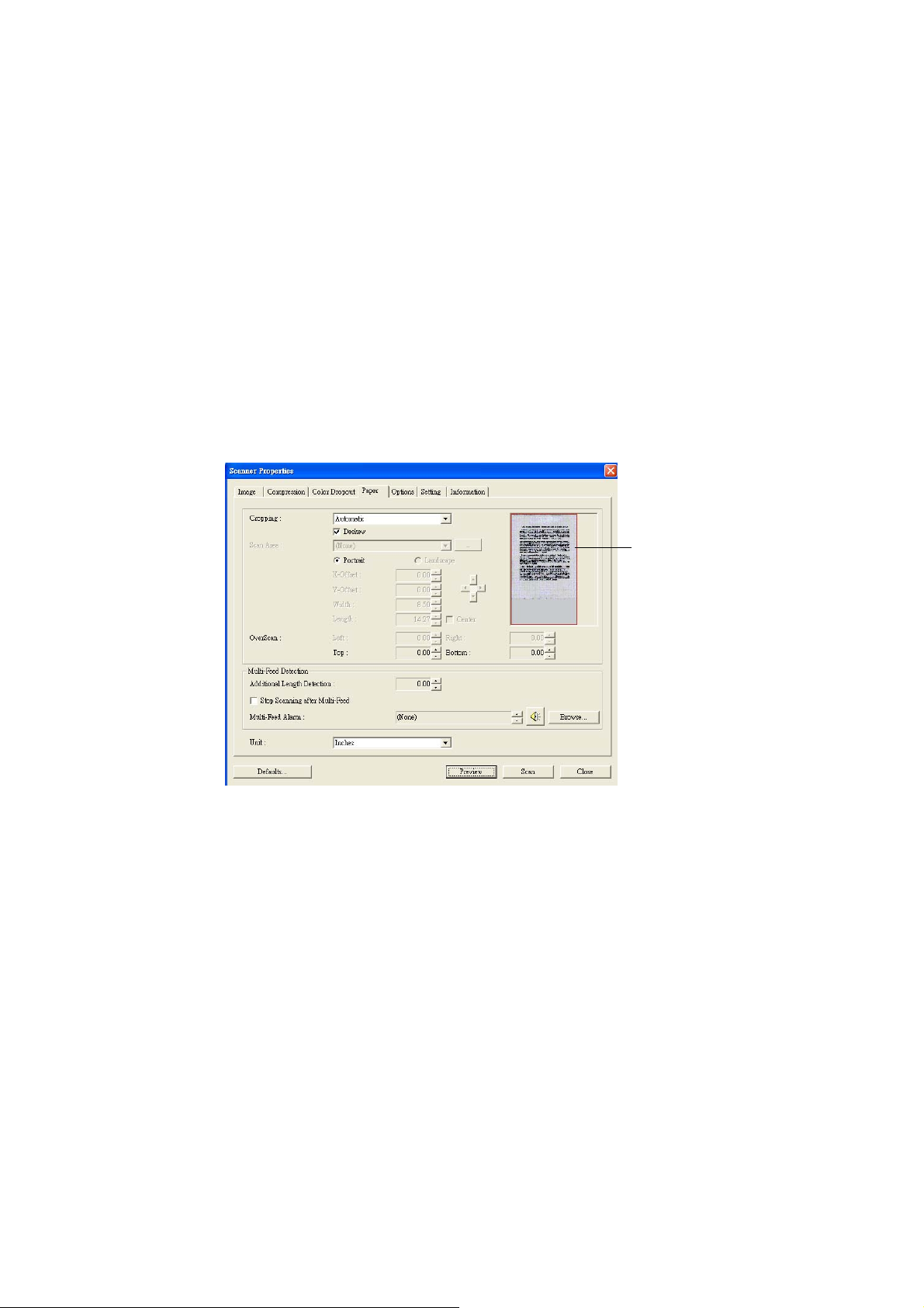
How to add the sound alarm:
1. Click the Browse button on the right side of the speaker
icon. The Open dialog box appears.
2. Choose your wave file.
3. Click the Open button. The wave file is added.
Units
Defines the primary measurement system. Inches,
Millimeters, and Pixels are available.
Preview
Click the Preview button. A quick, and low- resolution scan
will be made and appear in the Display window. From this
image, you can determine the area you want to scan.
The
Previewed
Image
47
Page 48
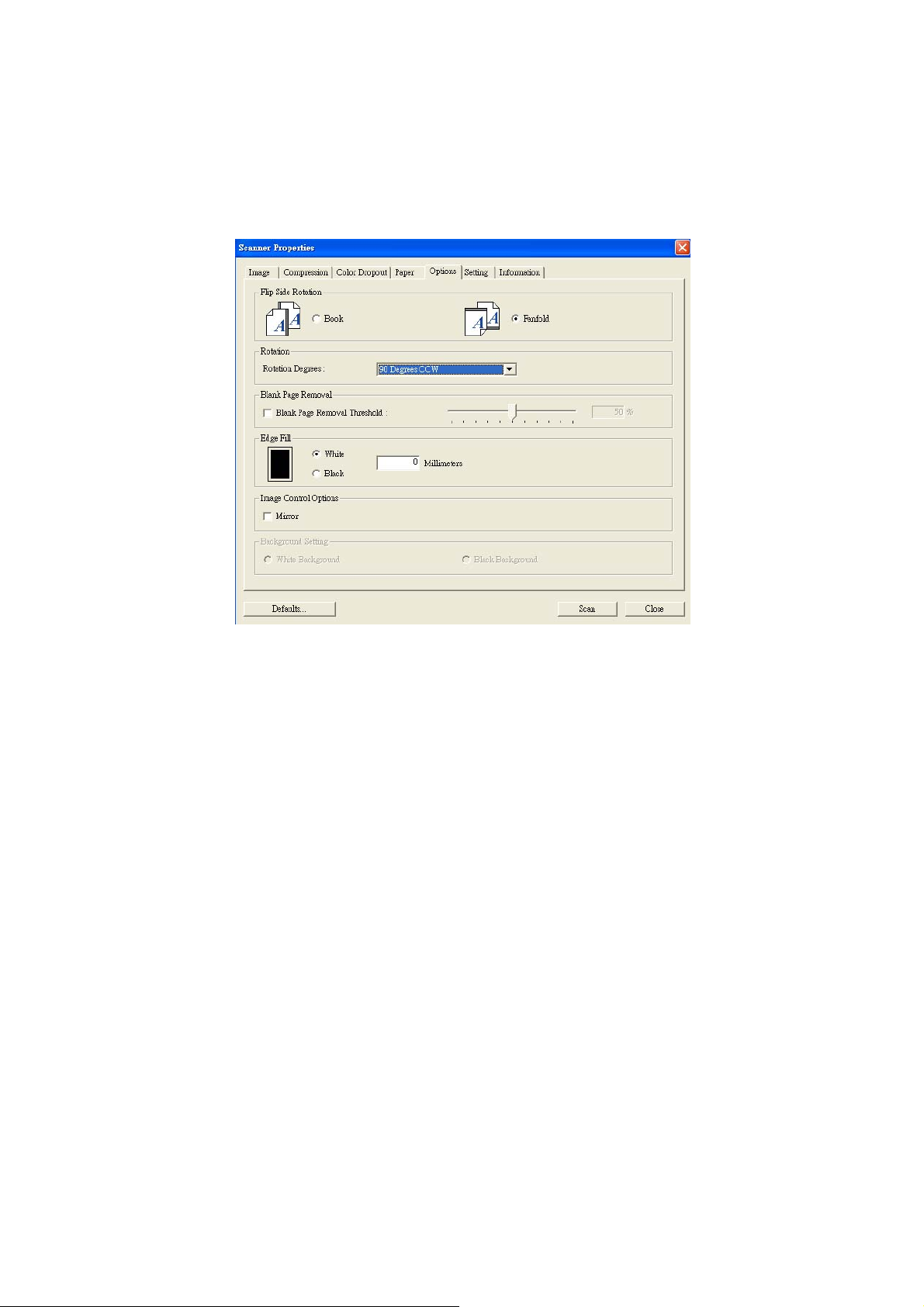
4.6 THE OPTIONS TAB
The Options tab allows you to set following additional image
processing settings.
The Option tab dialog box
48
Page 49

Flip Side
Rotation
This option allows you to select the
orientation of the double-sided
documents been fed and if “fanfold” is
selected, the image of the reverse side
will be rotated to 180 degrees.
This is applied to double-sided
documents which are viewed in portrait
(height is greater than width) but are
sometime fed into the scanner in
landscape (width is greater than height)
or vice versa. In this case, the image of
the reverse side has to be rotated
additional 180 degrees.
Choice: Book, Fanfold.
If “Book” is selected, the image of the
reverse side will not be rotated.
The following illustration shows the orientation of the
document which should be viewed in portrait but is fed
into the scanner in landscape
49
Page 50
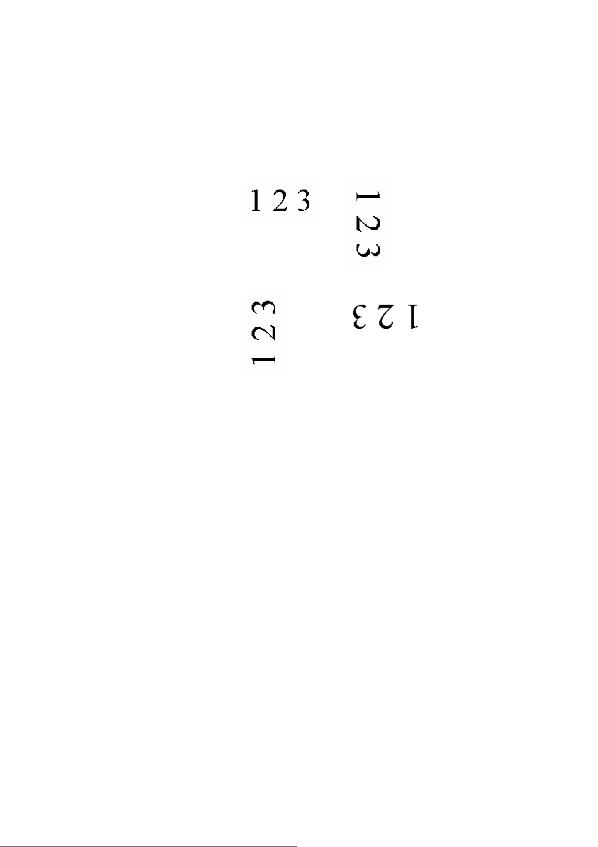
Rotate
Image
Choose the rotation angle from the drop
down list if you wish to rotate your
scanned image.
Choice: None, 90°CW(clockwise),
90°CCW(counter clockwise), 180°.
Blank Page
Removal
Original
Rotate 90°CCW
Check if you wish to remove the blank
page and move the slider to the left or
right to your desired threshold.
Rotate 90°CW
Rotate 180°
50
Page 51
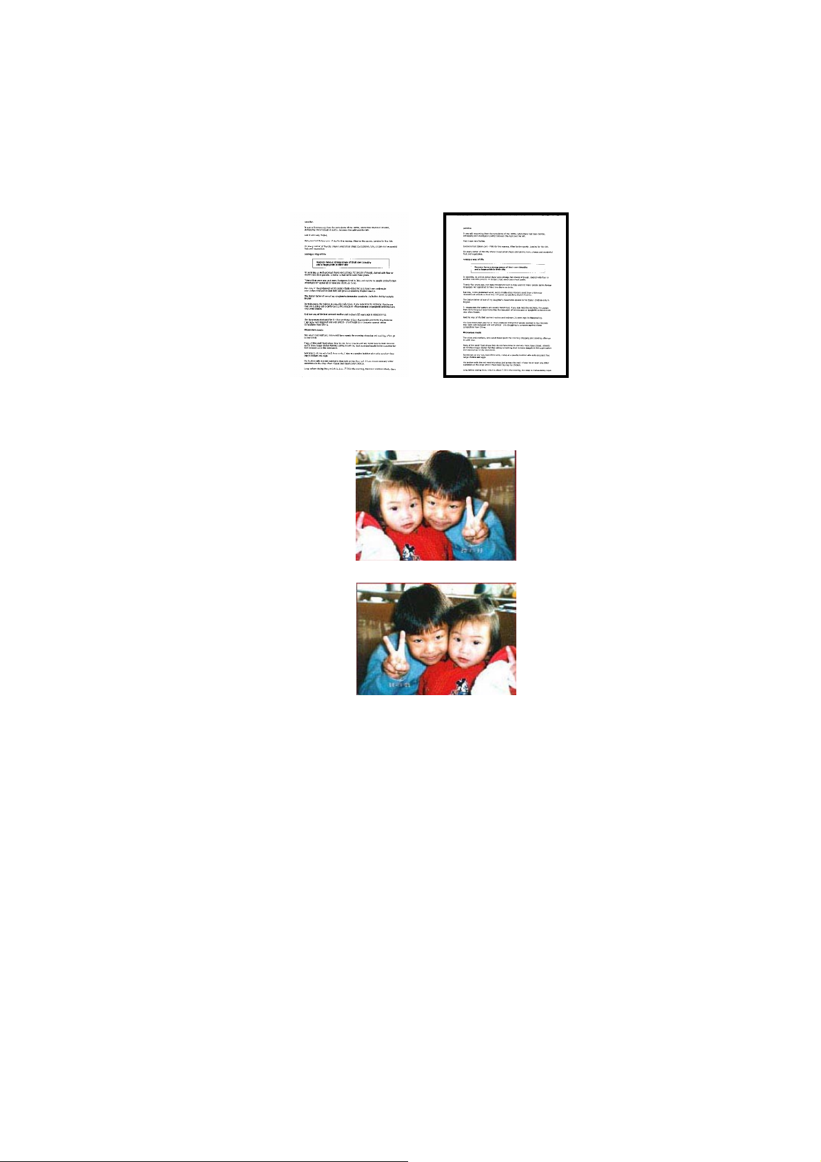
Edge
Fill
Check White or Black if you wish to add white or
black edge on the border of your scanned
image. Enter the value from 0 to 5 mm. Default
value is 0.
Image
Control
Option
Original
Edge Fill: 5mm (Black)
Check the Mirror box if you wish to reverse the
right and left side of your image.
Original
The Mirror Effect
51
Page 52
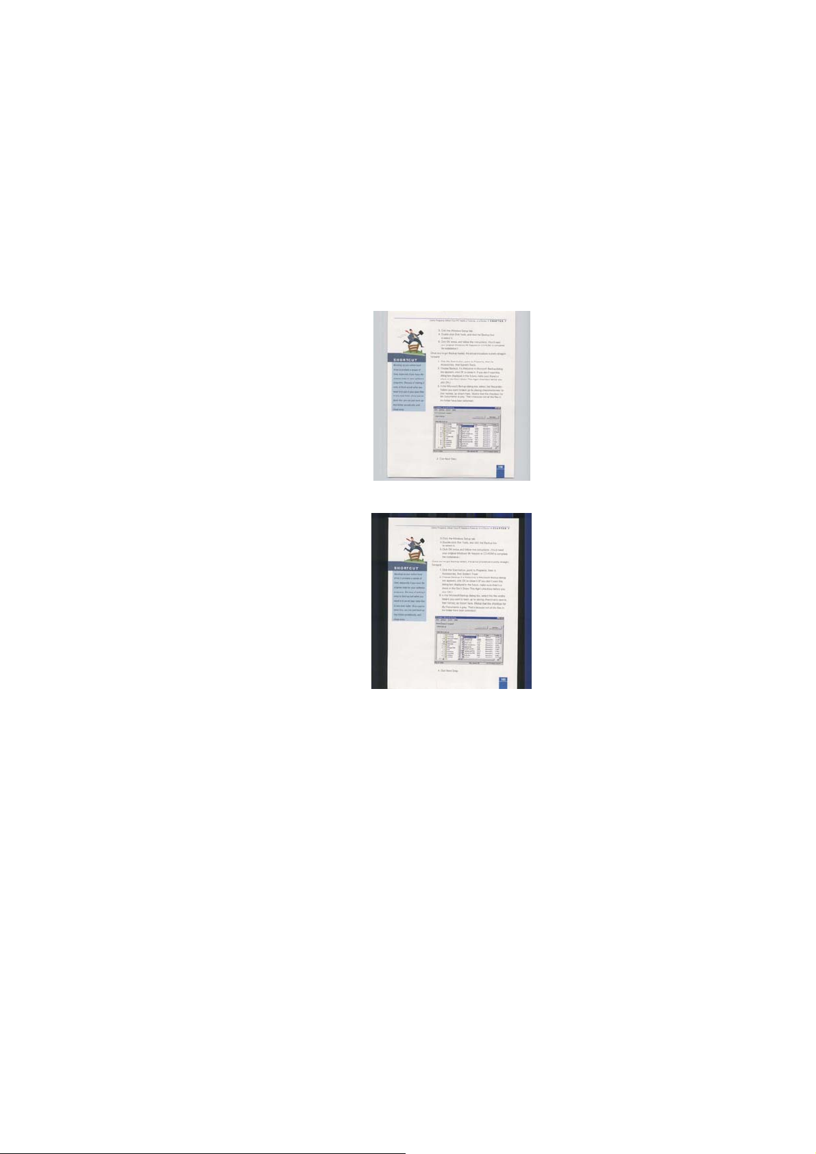
Background
Setting
This option allows you to set your scan
background.
Choice: White Background, Black
Background.
*This option varies based on type of
scanner and is available for the front page
in the ADF (auto document feeder) only.
For the rear page, only the white
background is available.
White Background
Black Background
52
Page 53
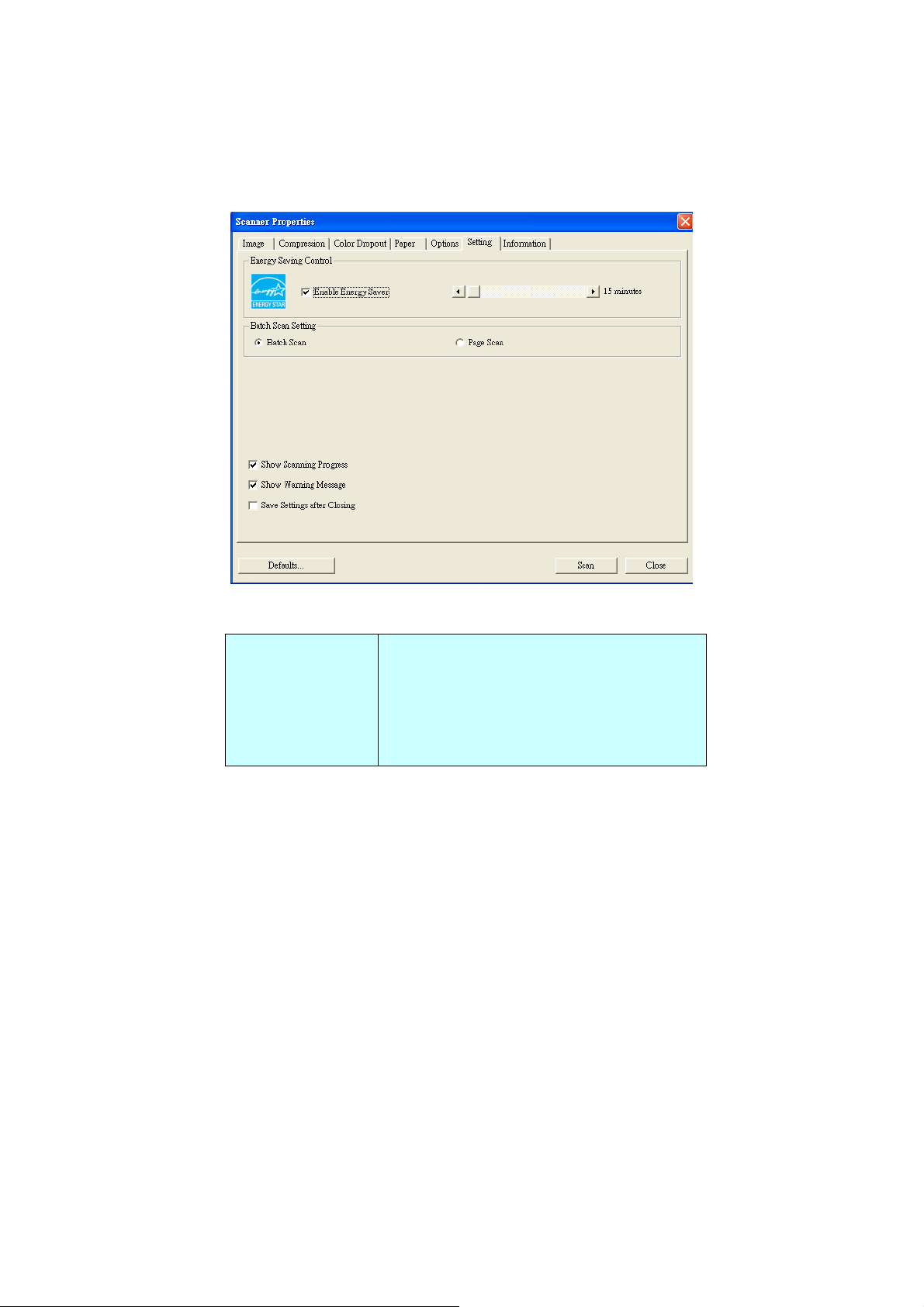
4.7 THE SETTING TAB
The Setting tab allows you to set the following settings:
Energy Saving
Control
The Setting tab dialog box
Check the Enable Energy Saver box
and move the slider to the right to set
the amount of time to start the energy
saver after your last action. The range
is from 1 to 720 minutes. The default
is 15 minutes.
53
Page 54

Batch Scan
Setting
•Batch Scan
To increase the scanning speed, the
scanner first scans a few pages of your
document and then sends these
scanning data to the application.
Therefore, during scanning, the
numbers of pages been scanned on the
scanner is somehow different with the
numbers of pages displayed on your
computer screen. Choose this mode if
you wish to complete your scanning
task at the fastest speed.
•Page Scan
If you choose Page Scan, during
scanning, the scanner will first scan
only one page of your document and
then send the scanned data to the
application and then scan the next
page and send the next data to the
application, and so on. Therefore, in
this mode, the scanning speed is
slower yet this helps to keep the same
scanning progress between the scanner
and your computer screen.
Show Scanning
Progress
Note: The option varied based on type
of scanner.
Check and the scanning progress bar
will be shown during scanning.
54
Page 55

Show Warning
Message
Check to show the warning messages
such as “ADF pad count exceeds
50,000 scans (the number varies
based on type of scanner). Please
replace the ADF pad and reset the pad
count.”
Save Settings
after Closing
Check to save your scanner properties
settings after leaving the dialog box.
Next time when you open the Scanner
Properties dialog box, the previously
saved settings will be shown.
55
Page 56
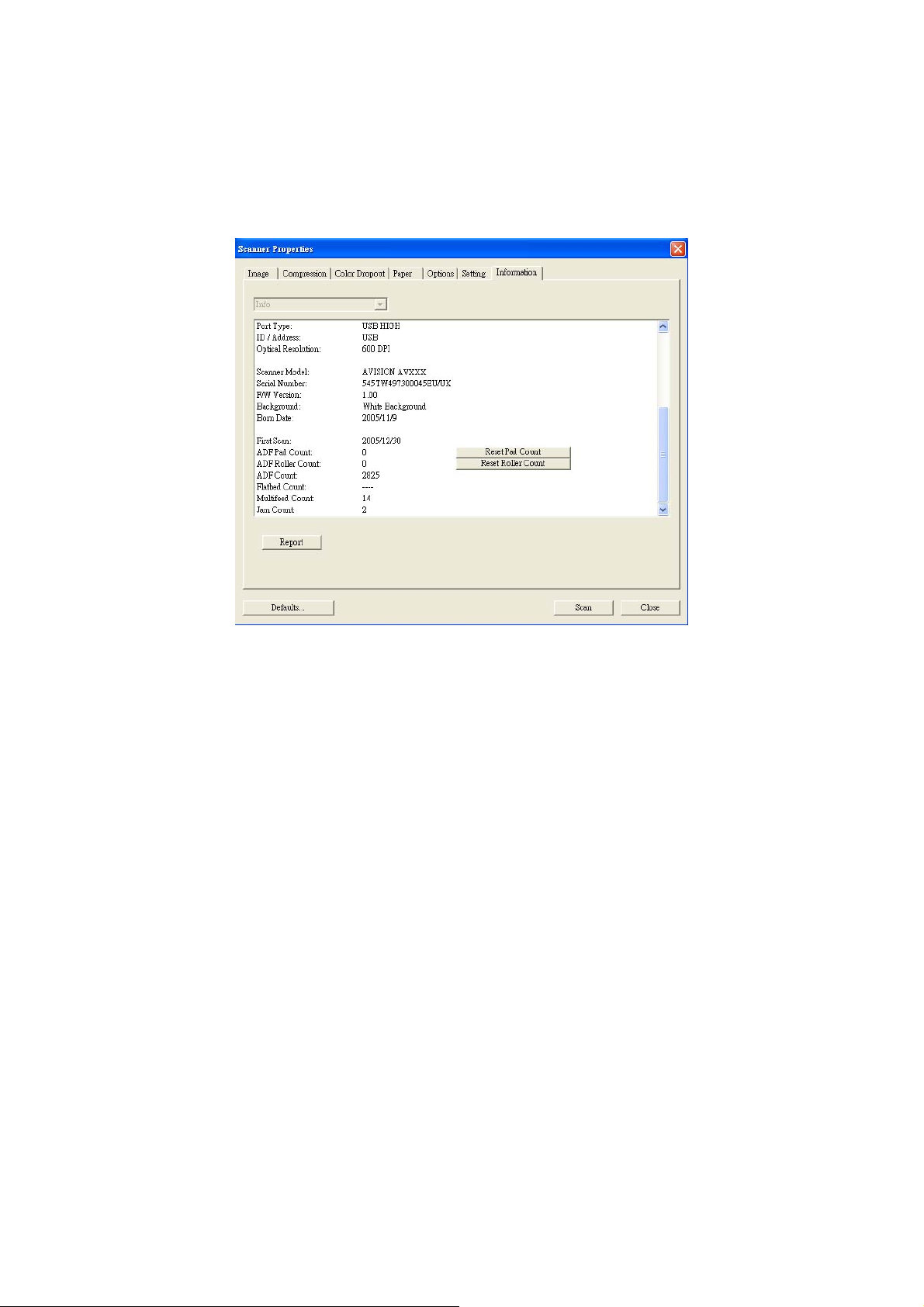
4.8 THE INFORMATION TAB
The Information tab displays the following system and
scanner information.
The Information tab dialog box
The “Report” button:
If you encounter any error message while using the scanner,
click the Report button. A report.txt file (C:\AVxxx) will be
generated. Please send this file to the nearest service
center for trouble shooting.
56
Page 57

The “Reset Pad Count” button」:
After scanning approximately 50,000 pages (the number
varies based on type of scanner) through the Auto
Document Feeder (ADF), the ADF pad may be worn out and
you may experience problems with document feeding. In
this case, it is highly recommended to replace the ADF pad
with a new one. (Please refer to the manual for proper
replacing procedure.) For ordering the ADF pad, please
consult your nearest dealer. After replacing the ADF pad,
click the “Reset Pad Count” button to reset the pad count.
The “Reset Roller Count” button」:
After scanning approximately 200,000 pages through the
ADF, the ADF roller may be worn out and you may
experience problems with document feeding. In this case,
it is highly recommended to replace the ADF roller with a
new one. After replacing the ADF roller, click the “Reset
Roller Count” button to reset the roller count.
Note:
The lifetime and the replacing procedure vary based on
type of scanner. Please consult your nearest dealer for
more details.
57
Page 58
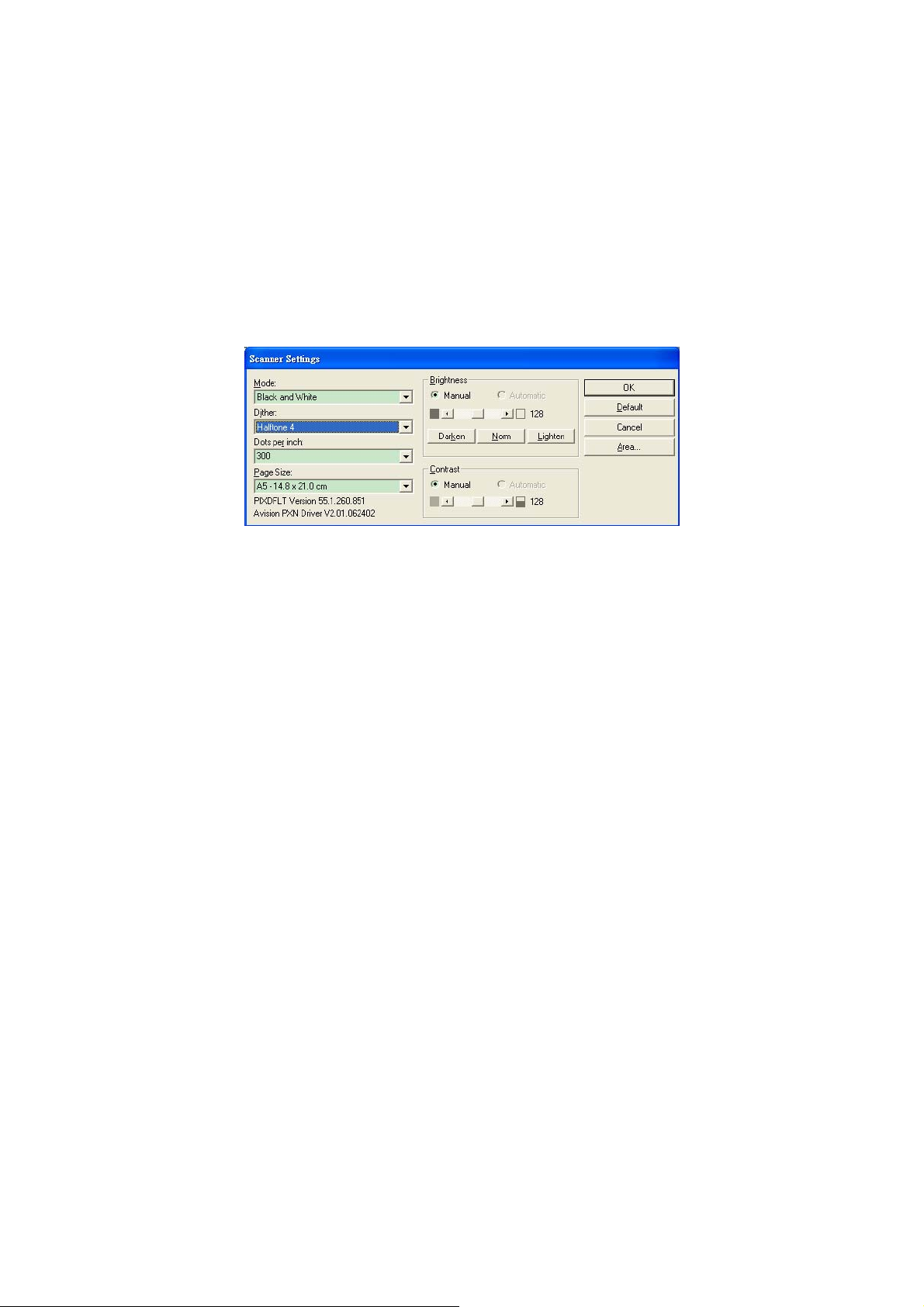
5. ISIS INTERFACE
OPERATION
The ISIS driver operation method is similar to the TWAIN’s.
Every function on the ISIS interface screen is briefly
described as below:
Mode: Select one of scan modes, including B/W, gray,
color options.
Dither: 5 halftone levels available, can be disabled.
Dots per inch: Select your desired resolution.
Paper Size: Select your desired paper size.
Brightness: Adjust your scan image brightness or
darkness.
Contrast: Adjust the range between the darkest and the
lightest shades in the image.
Default: Click to reset all settings.
Area: Select your desired scan area or position.
58
Page 59
6. USING THE BUTTON
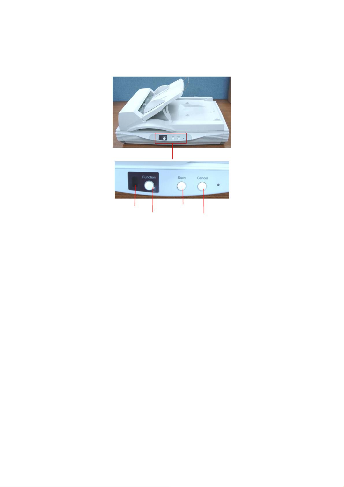
The convenient buttons on the scanner is shown as below:
Function Display
The Scan Button
Function Selector
The Cancel Button
59
Page 60

6.1 INSTALLING BUTTON MANAGER
To use the buttons on the scanner, you need to install the
Button Manager. To ensure the Button Manager work
properly, please FIRST install Button Manager before
installing the scanner driver.
Installing the Button Manager is easy. Insert the supplied
CD to your CD-ROM drive and follow the instructions on the
screen to complete the installation.
Button Manager provides you an easy way to scan your
document and then link the scanned image to your
designated software application. All this can be done by a
simple touch of the button on the scanner. Yet, before you
scan, it is recommended to check the button configurations
first to ensure a proper file format and a destination
application.
60
Page 61
6.2 CHECKING THE BUTTON CONFIGURATIONS
BEFORE SCANNING
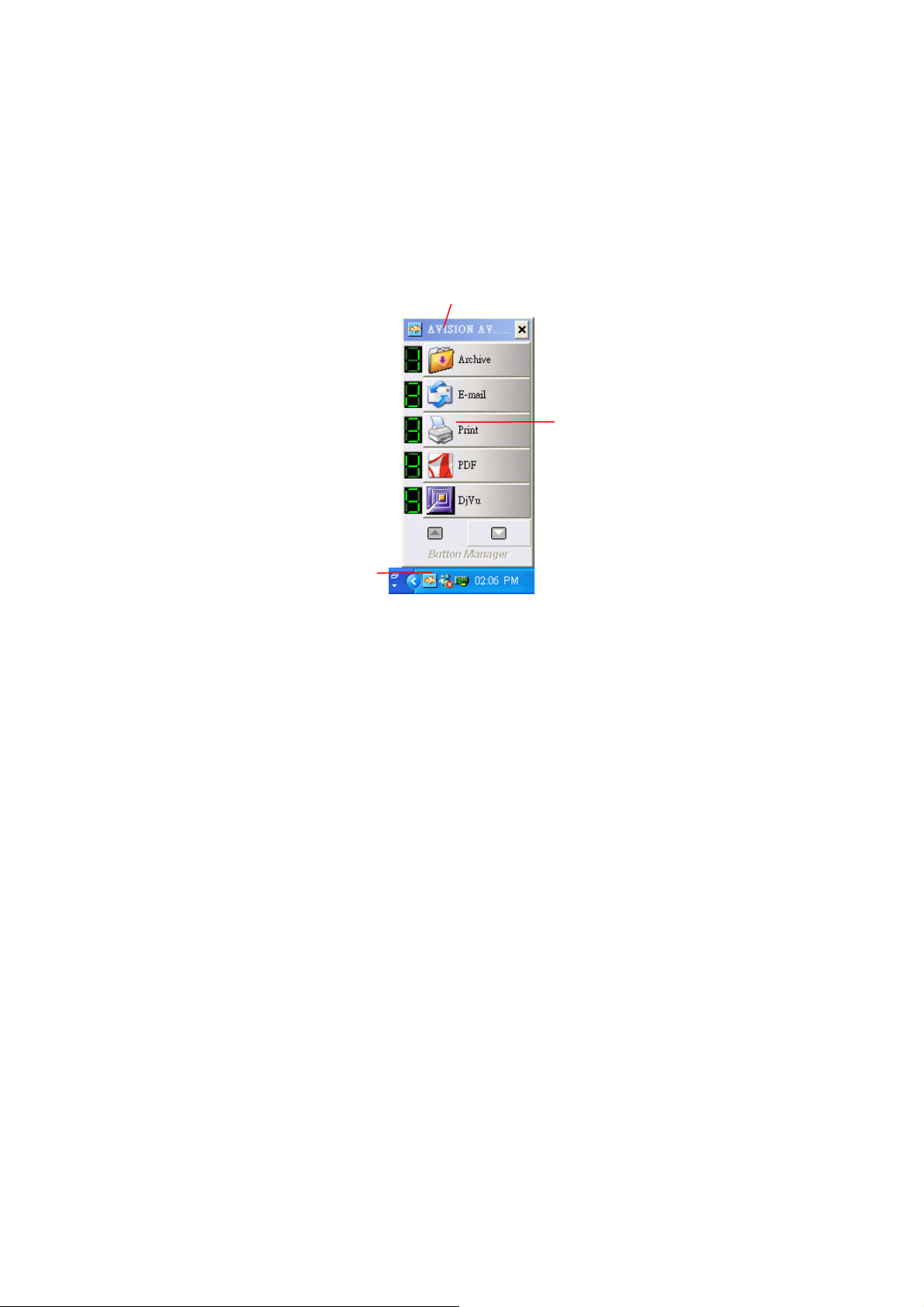
1. After the Button Manager and the scanner driver have
been successfully installed on your computer, the
Button Panel will be displayed in the Windows System
Tray at the bottom right corner of your computer
screen.
This indicates the scanner model
The Function
Icon
The Button
Icon
The Button Panel
2. The Button Panel shows the first five scanning buttons.
Right-click the button (function) you wish to check.
The Button Properties window appears.
61
Page 62
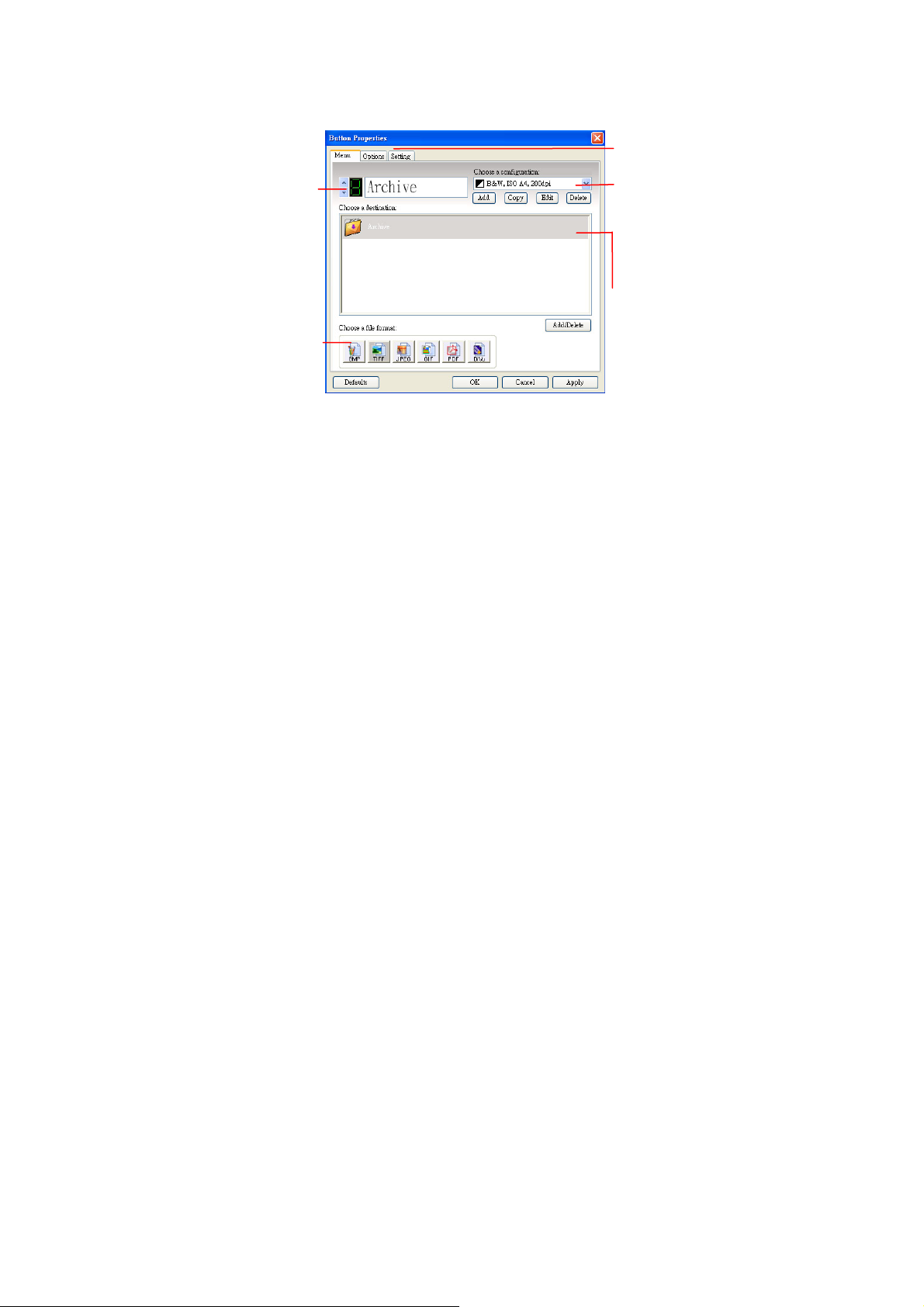
The button
number and
name.
The file format
of the scanned
image.
Click to select
options or
setting.
The scan settings
for the selected
button. (in this
case button #1).
The destination
application. (This
is the application
that opens after
you have finished
scanning.)
The default setting is indicated in highlighted color. If
you wish to change the setting, use this window to reset
the setting for the file format, destination applicat ion, or
other scan settings. See “Configuring the Button” in the
subsequent section to reset the settings.
3. Click the OK button to leave the window.
62
Page 63
6.3 THE DEFAULT BUTTON SETTINGS
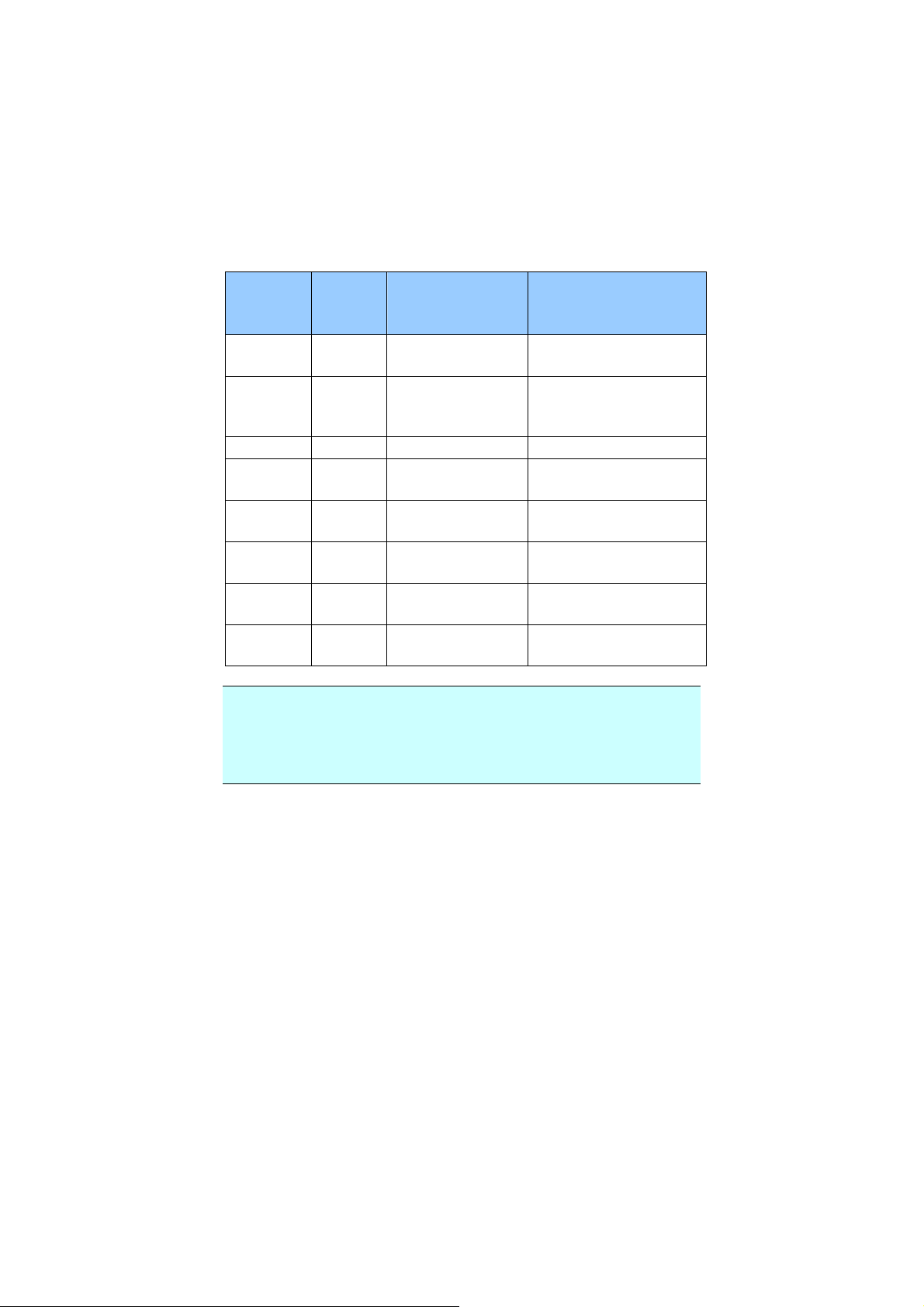
The scanner is shipped with preconfigured button settings
for your basic scanning tasks such as scan-to-folder, scanto-email, and scan-to-printer. The following table shows
these factory default settings. You can change any of these
settings.
Button
Numbe
Name Destination
Application
Preset Scan
Settings
r
1 Archive Folder B&W@200 dpi, A4,
TIFF
2 E-mail Microsoft
Outlook
Gray@200 dpi, A4,
JPEG
Express
3 Print Printer B&W@300 dpi, A4
4 PDF Acrobat Reader B&W@200 dpi, A4,
PDF
5 DjVu Document
Express
6 Scan roxio
PhotoSuite
B&W@300dpi, A4,
DjVu
Color@100 dpi, A4,
JPEG
7 Paint Microsoft Paint Color@100 dpi, A4,
BMP
8 OCR Document
Express
B&W@300dpi, A4,
TIFF
Note:
To accurately use the default settings, you need to install
the necessary software applications such as roxio
PhotoSuite, Document Express, or Adobe Acrobat Reader
before installing the scanner driver.
63
Page 64

6.4 SCANNING FROM ONE TOUCH OF THE BUTTONS
1. Adjust the paper guide for the width of paper and load
the document with their tops into the automatic
document feeder.
2. Check the number on the LED screen to ensure if you
are selecting the proper scan settings and destination
application. (For example, if you want to scan with
button #4, which open roxio PhotoSuite and display the
scanned image in the main window of roxio PhotoSuite,
the LED screen should show 4).
3. Press the Scan button on scanner.
64
Page 65
5
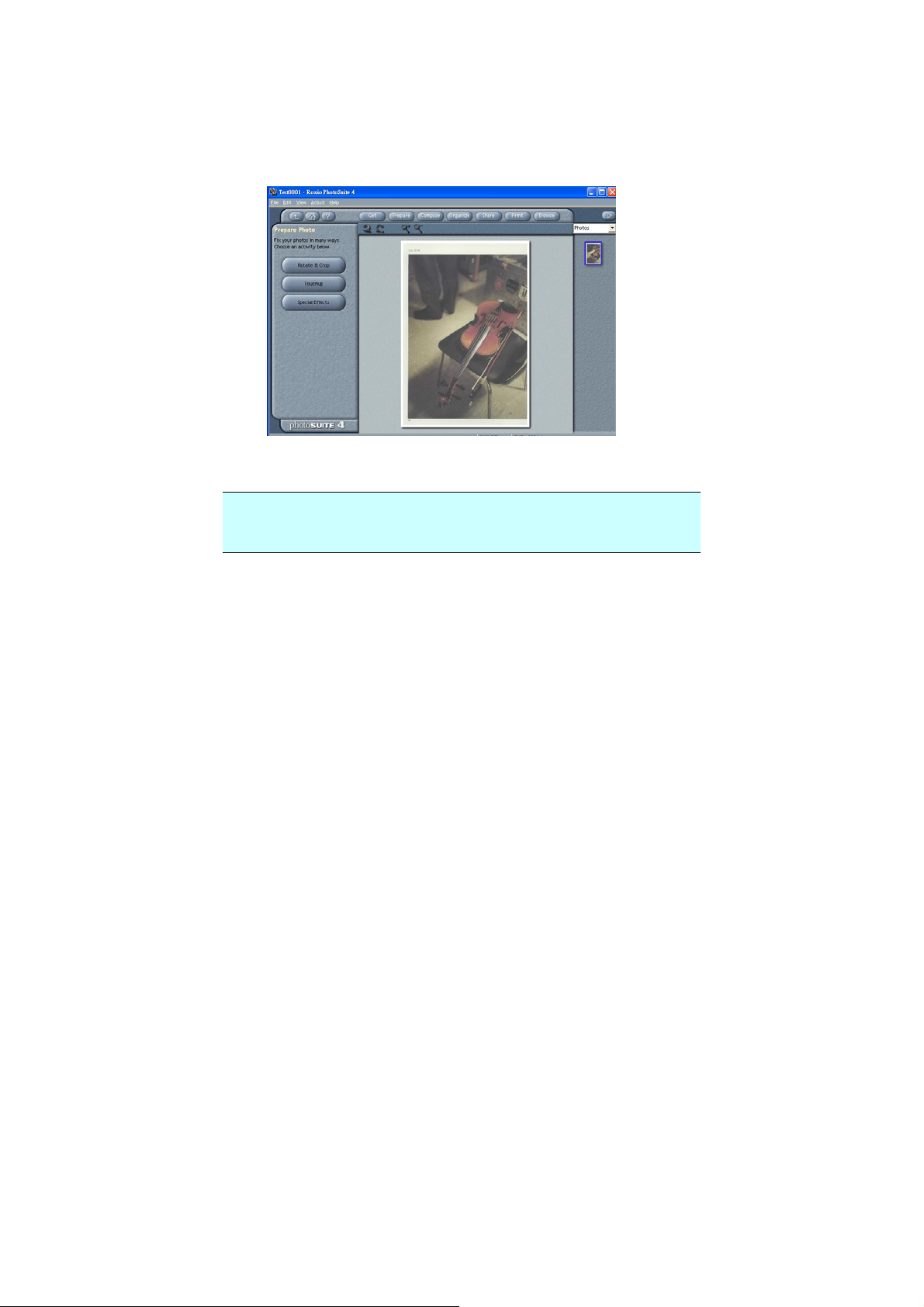
4. After the scanning is finished, the roxio PhotoSuite will
be launched and the scanned image appears in the
main window of roxio PhotoSuite as below.
Note:
For details information on how to use the Button Manager,
please refer to the user’s manual in the supplied CD.
6
Page 66

6.5 PERFORMING CONTINUOUS SCAN FROM THE
FLATBED
If your scanner comes with a flatbed module, Button
Manager provides you a convenient feature to perform
continuous (multi-page) scan from the flatbed. Simply
inserting next page of your document and then pressing the
Scan button, your multi-page scan from the flatbed can be
completed. This feature is particularly useful when you
need to scan inside pages of a book.
To perform continuous scan from the flatbed,
1. Open the document cover.
2. Place your document with the text facing down on the
glass. Make sure that the upper left corner of your
document is near the home position as marked by
arrow.
Document
Document
Glass
3. From the Button Properties window, choose your file
format to be PDF, TIFF, or DjVu.
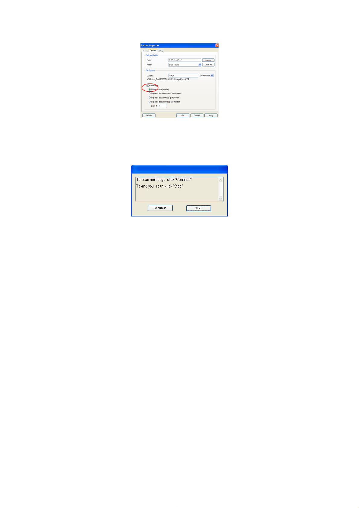
4. From the Options tab in the Button Properties window,
choose “Multi-Page”.
66
Page 67
7
5. Check if the number displayed in the LCD screen is
your favorable setting for the scanned image.
6. Press the Scan button on the scanner.
7. When the scanner completes first-page scan, a
“Continue or stop” dialog box appears.
6
Page 68

8. Place next page of your document on the glass.
9. Choose “Continue” or simply press the Scan button on
the scanner to scan next page.
10. If your scan is completed, click “Stop” to close the
dialog box.
Note:
1. The scanner is designed to automatically set your scan
source. If your scanner is equipped with both the
auto document feeder and the flatbed, the scanner
can automatically set your scan source whenever
there is paper on the source. However, if there is
paper on both the auto document feeder and the
flatbed, the scanner will set auto document feeder to
be the scan source.
2. If you choose to perform flatbed scan, the scanner can
still perform “automatic crop” and “deskew” for the
scanned image. However, the “Multi-feed Detection”
and “Duplex” functions will be disabled.
68
Page 69

7. CARE AND
MAINTENANCE
7.1 CLEANING THE ADF
The scanner is designed to be maintenance free. However,
it still needs to be cleaned occasionally to ensure optimum
image quality and performance.
From time to time the pad assembly and feeding rollers
may become contaminated with ink, toner particles or
paper dust. In this case the scanner may not feed
documents smoothly or several documents may feed at
once. If this occurs please follow the cleaning procedures
to return your scanner to its original state.
The cleaning procedures
i). Moisten a cotton swab with isoprophyl alcohol (95%).
(Cleaner kits are available from PictureVision.)
ii). Carefully open the ADF to the left . Wipe the feeding
rollers by moving the swab from side to side. Rotate
the rollers forward with your finger and repeat the
above cleaning procedures until the rollers are clean.
Be careful not to snag or damage the pick springs.
iii). Wipe the pad in the direction from top to bottom. Be
careful not to hook the pick springs.
iv). Close the ADF unit. Your scanner is now ready for
use.
69
Page 70
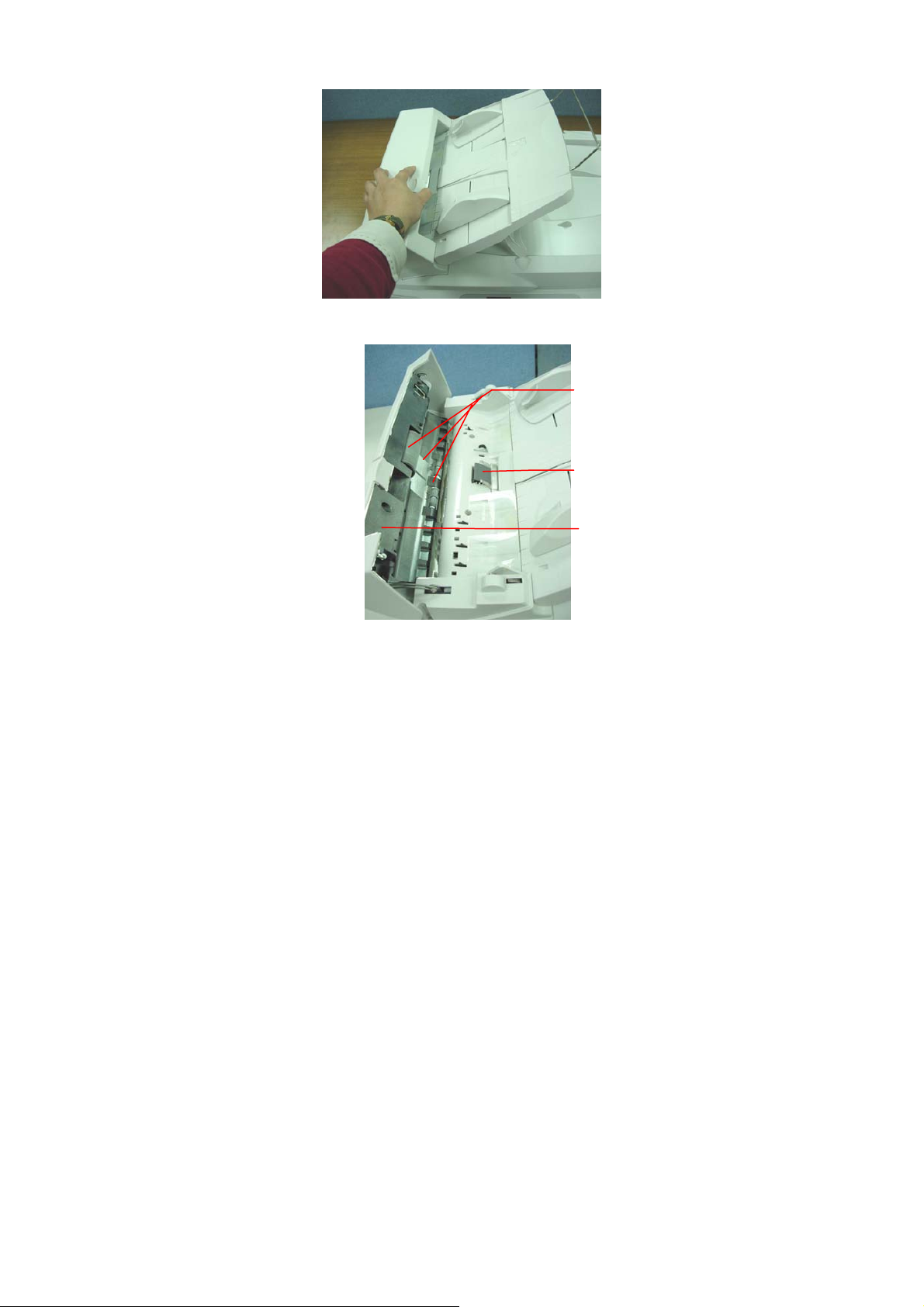
ADF Roller
ADF Pad
ADF Unit
Figure 6-1 Clean the ADF unit
70
Page 71
7.2 REPLACING THE ADF SNAP-IN PAD MODULE
After scanning approximately 20,000 pages through the
ADF, the separation pad may be worn out and you may
experience problems with document feeding. In this case,
it is highly recommended to replace the pad module with a
new one. For ordering the pad module, please consult your
nearest dealer and follow the procedure below to replace it.
Disassembling Procedure
1. Open the ADF cover.
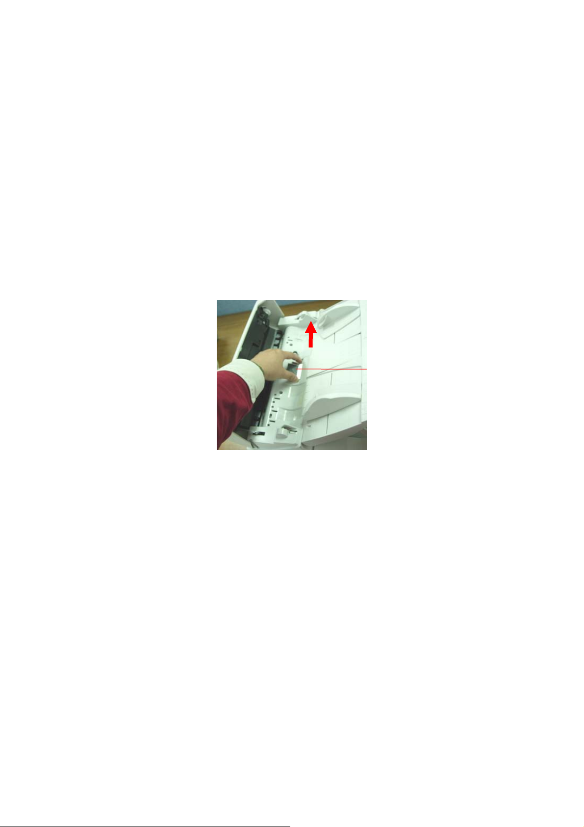
2. Remove the ADF snap-in pad module by pulling out
the upper part of the pad clamp as shown in below.
71
ADF Pad
Page 72
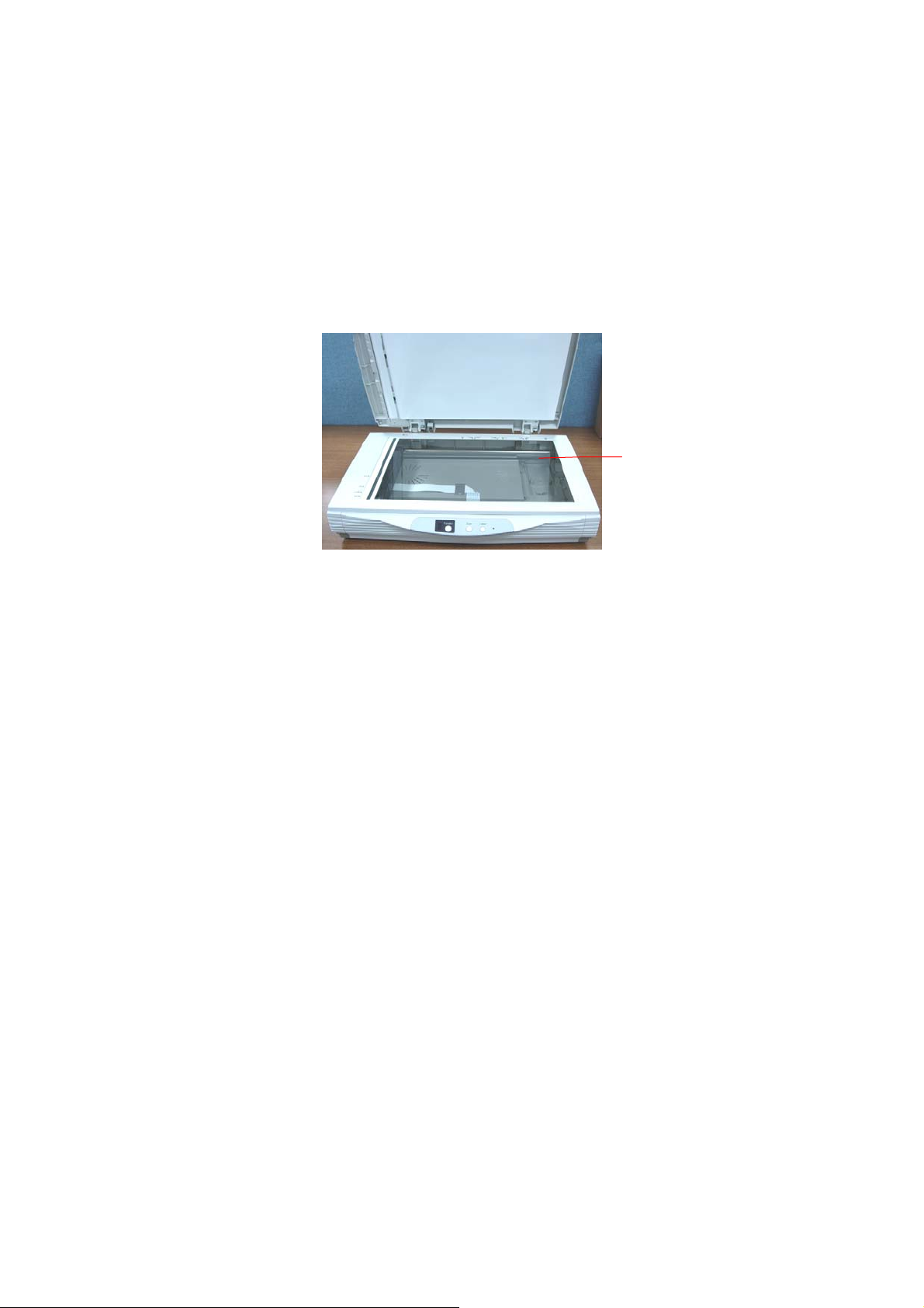
7.3 CLEANING THE GLASS
The procedures
1) Soak a cotton swab with some isopropyl alcohol. (95%)
2) Open the document cover as shown in Figure 6-2. Wipe
the document glass by moving the swab from side to
side.
3) Close the document cover. Your scanner is now ready
for use.
1
1. Document glass
Figure 6-2 The cleaning area
72
Page 73

8. TROUBLESHOOTING
If you have problems with the operation of your scanner,
please check the following troubleshooting hints.
8.1 FREQUENTLY ASKED QUESTIONS
Question: When the scanner is powered on, it makes
noises and won’t stand ready.
Answer: There are two possibilities:
1) You might fail to push the scanner shipping
lock to its “use” position. If this is the case, pull
the scanner status switch to its “use” position
first.
2) The scanner is not placed on an even, flat
desktop surface. This may cause the scanner to
malfunction.
Question: The scanner is powered on, but the lamp does
not light up.
Answer: The lamp is probably out of order. Contact your
local dealer or distributor to replace the lamp.
For your information, the average life time of the
lamp is about 15,000 hours and the operating
temperature for the scanner is between
10°C(50°F)
and 40°C(104°F).
73
Page 74

Question: While scanning, the scanner often makes noises,
or it scans back and forth.
Answer: Usually this means the memory of your computer
is not enough or the speed of your CPU too slow.
Please try to increase your memory to at least
32M or replace your CPU with Pentium or later.
Question: Why is it that the scanned image always
comes out to be too dark?
Answer: 1) Modify the Gamma setting to1.8~2.2 for your
monitor and, when printing, set the Gamma
setting to 2.2 for your printer.
2) Adjust the Brightness setting from the TWAIN
user interface to get a brighter image.
Question: The scanner works well except for the line art
image. The lines in the image seem to be much
thicker than the original one.
Answer: Increase the Brightness or adjust the Threshold
setting to improve line art image.
74
Page 75

5
8.2 TECHNICAL SERVICE
Technical support for Avision scanner is provided at Avision
Technical Assistance Center (ATAC). Before contact with
ATAC, please prepare the following information.
• Scanner serial & revision number (located on the
bottom
of the scanner)
• Hardware configuration (e.g., your host CPU type,
RAM size, free disk space, display card, interface card,
etc.)
• The name and version of your software application
• The version of your scanner driver.
Please call us at:
Avision Inc.
Address: No.20, Creation Road I, Science-Based
Industrial Park, Hsinchu, Taiwan
Telephone
+886 (3) 578-2388
number:
Fax number: +886 (3) 577-7017
Web Site: http://www.avision.com
E-mail: [email protected]
7
Page 76

9. SPECIFICATIONS
All specifications are subject to change without
notice.
Model Number DT-0603H
Scanner Type Flatbed & ADF
Scanning Mode Color/Grey/Black & White
Optical Resolution 600 * 600 dpi
Maximum Resolution 1200 dpi
Light Source Cold cathode fluorescent lamp
Maximum Scanning Size 11.8” x 17”
Interface High Speed USB 2.0
AC Power Line 100~240Vac ,50/60Hz
Power Requirements 24Vdc, 2A (Supplied by
adaptor)
Power Consumption < 32 watts (operation)
< 6 watts (standby)
Humidity 20% to 80% RH
Operation Temperature
Storage Temperature -10 to 50°C
Dimension 589 x 428 x 317 mm (WxDxH)
Weight 10.3 kgs
10°C to 40°C
76
 Loading...