

Page 1

DIVA Revolution 195
User Guide
Page 2

About Avintage and French Corner Cellars
Avintage is the premium line of wine cabinets made by Frio Group, Europe’s leader in wine
cabinets. Located in France, Frio’s sole activity is the development and manufacturing of
wine cabinets. Frio is recognized for its expertise resulting from years of servicing wine
enthusiasts.
Created by a Winemaker, Avintage has developed a reputation as outstanding
manufacturer and has earned the loyalty of many wine collectors and lovers over the past
20 years. Exclusively built in Europe, Avintage offers superior quality wine cabinets with a
wide portfolio.
French Corner Cellars is the exclusive distributor of Avintage wine cabinets in the USA and
Canada. Already involved in wine activities, French Corner Cellars owners decided to
expand their services to provide means to preserve and serve wine in optimum conditions.
Located in the New York Capital region, French Corner Cellars serves private customers
as well as businesses wishing to enhance the potential of their wine collection. The quality
of our cabinets is also reflected in the range of services and the warranty we offer our
customers.
We thank you for your confidence and business. We trust you will enjoy your new Avintage
wine cabinet.
Page 3

USA
2
USA/CA&
Contents
Warning and Safety Instructions
3
- 4
&
Get to know your wine cooler 5
&
Before
use
6 - 7
&
Installation and start-up 8
&
Operation & functions 9 – 11
Defrosting and cleaning
12
Technical data 13-14
&
Reversible door 15 - 22
&
Accessories 23 - 24
Customer Care and Troubleshooting
25
&
Warranty and spare parts
26
&
Disposal
27
Page 4

USA
3
USA/CA&
Warning and safety instructions
&
Warnings and Safety Instructions mentioned in this guide are not meant to cover all possible
instructions and situations that may occur during the cabinet lifetime.
&
●Keep ventilation openings in the cabinet
or in the built-in structure clear of
obstruction.
●Do not use other mechanical devices or
other means to accelerate the defrosting
process than those recommended by the
manufacturer.
●Do not damage the refrigerant system
&
●Do not use electrical appliances inside
the refrigerated storage compartment,
unless they are of a type recommended
by the manufacturer.
●Do not connect the wine cellar to multiuse electrical adapters.
●Do not use your cellar outdoors. Do not
expose it to atmospheric agents.
(Humidity, moist, extreme temperatures
etc.).
●This cabinet is not intended nor designed
for use by children or people with
reduced physical, sensory or intellectual
capacities, or by people lacking
experience or knowledge unless they
are watched or have received
instructions on how to use the device by
a person responsible for their safety.
Before you dispose your old device:
- Take off the doors.
- Leave the shelves in place so that
children may not easily climb inside.
●Do not store explosive substances such
as aerosol cans with a flammable propellant in this cabinet.
●Do not operate the cabinet in the presence
of explosives and/or flammable fumes.
●Always keep the keys in a separate place
and out of reach of children. Keep
children away from the cellar. Do not let
them play with the device cabinet.
●Disconnect the cellar before performing
any servicing or cleaning operation
(disconnect the power plug cord or the
corresponding circuit breaker depending
on the model).
●In case liquid is accidentally spilled
(broken bottle or other) on the electrical
elements (motor or other), immediately
disconnect the power plug cord.
●Make sure that your electrical voltage
and power rates correspond to the indications on the name/data plate on your
wine cellar, which must be connected
to
a
grounded 3 prong electrical outlet. Repairs or incorrect connections will lead to
dangerous conditions. Have your electrical installation checked by a professional
if you are in doubt.
●To avoid any risk if the power cord is
damaged, have it replaced by an approved technical centre, the dealer, or an
authorized service representative.
●Never pull on the power cord. Never carry
the device by the cord and never pull on
the cord to disconnect it. Grip the plug
connected to the wall outlet and unplug.
●Place the power cable in a way to protect
it from any damage or risks of falling.
Page 5

USA
4
USA/CA&
&
●To avoid any risk of fire electric shock or
injury, do not dismount the cellar.
&
●To avoid any risk of fire, electric shock or
injury, do not immerse the power cord,
the plug or the device in water or any
other liquid.
●The power cable must not come in contact
with sharp edges, hot parts or any source
of heat.
●If your cellar is damaged (major shock) or
has suffered from any kind of incident
(over voltage due to lightning, flooding,
fire), it may prove dangerous. Disconnect
the power plug and have the device
checked by an approved professional
technician.
●An electrical device must only be repaired
by qualified personnel; unqualified repairs
may lead to serious dangers for the user.
●For safety reasons do not use an electrical extension cord.
●Always remove all bottles before moving
this cabinet.
●Frost formation on the interior evaporator
wall and upper parts is a natural phenomenon. Therefore, the cabinet should
be defrosted during normal cleaning or
maintenance.
●Please note that changes made by the
owner to the cabinet construction will
cancel all warranty and product liability.
●This cellar is designed to conserve exclusively wine. Do not store food!
●This wine cellar should not be recessed
or built in an endorsed cabinet; it’s designed for freestanding installation only.
●Do not splash or spray water from the
hose on or in the cabinet.
●The cabinet shall not be plugged to an
ungrounded electrical power.
●The cabinet is supplied with a UL listed,
3 wire power cord ready for connection
to a 120V, 60Hz supply.
Page 6

USA
5
USA/CA&
Get to know your wine cabinet
&
&
&
&
&
&
&
&
&
&
&
&
&
&
Light
Control panel
Charcoal filter
Wooden shelf
Sealing strip
Nameplate
Kick plate
Lock
Adjustable
feet
&
&
&
&
&
&
&
&
&
&
&
&
&
&
&
&
&
Page 7
USA
6
USA/CA&
&
Before use
At cabinet reception
Check that the cabinet and or box have not been damaged during transport. Do not
put in use if the cabinet has been damaged during transport.
Transport Damages must be reported to French Corner Cellars within 24 hours
of the delivery.
&
Remove the packaging. Clean the inside of the cabinet using warm water with a mild
detergent. Rinse with clean water and dry thoroughly (see cleaning instructions page
18). Use a soft cloth.
&
If the cabinet has been laid down during transport, or if it has been stored in cold
surroundings (colder than +41°F), it must be allowed to stabilize in an upright position
for at least twenty-four (24) hours before being
switched on.
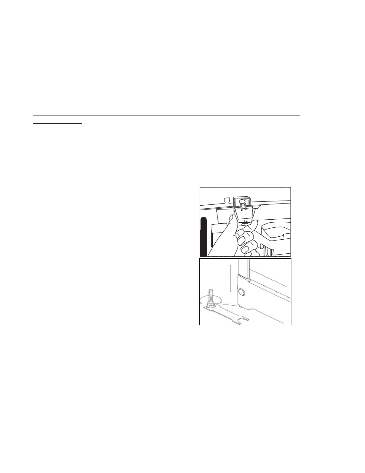
The pieces on the rear of the cabinet ensure air
circulation by providing enough space for the
cabinet to operate normally. Fit the two caps
supplied with the cabinet as shown on the picture.
&
&
Setting up
It’s important to have the cabinet leveled. It can
be adjusted by screwing or unscrewing the
adjustable feet at the front of the cabinet.
Use a spirit level to check that the cabinet is
absolutely level sideways.
&
&
Installing shelves
There are three different shelf models.
Fixed shelves
Place the shelf on top of the internal wall supports, and then slide it towards the back
of the cellar. Make certain the wedge is on the upper end of the shelf.
Display shelves
Use two sets of side supports per display shelf. The posterior part of the shelf sits on
the upper level, the front part of the shelf sits on the lower level supports, creating a
tilted shelf allowing bottles to be placed in an angled position.
Sliding Shelves
Place the 2 rails on the internal wall supports, with the wheels at the front.
Then insert the shelf between the rails, with the wheels on the back, in diagonal from
the top; once placed between the rails slide is towards the back.
Page 8
USA
7
USA/CA&
&
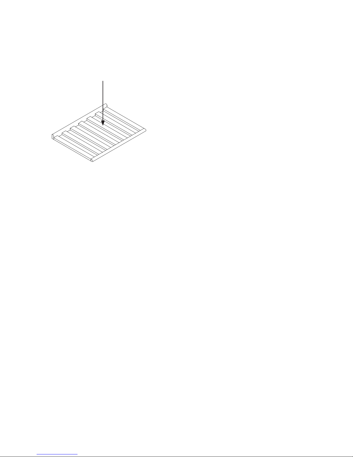
Max weight on the shelves (fig. 1)
&
Max. 85 kg./187 pounds
&
&
&
&
&
&
&
&
&
&
fig. 1
Page 9
USA
8
USA/CA&
&
Installation and start-up
Location
Make sure to measure the area where the DIVA Revolution 195 will be located and
ensure there is enough clearance on all sides (3 inches on the top of the cabinet, 1
inch on the sides and back).
For safety and operational reasons, the cabinet may not be installed outdoors. It
should be placed on a leveled surface in a dry, well-ventilated room (max. 75%
relative air humidity). Never place the cabinet close to sources of heat such as
ovens, stoves or radiators; and avoid placing it in direct sunlight.
&
Ambient temperature.
The winter function will guaranty the wine cabinet to operate at an ambient
temperature as low as 41ºF.
Installation
This wine cellar should not be recessed, nor should it be placed in an enclosed
cabinet. It is designed for free standing installation only.
Avoid risk of electrical shock:
- Plug into a grounded 3-prong outlet.
- Do not move the ground plug.
- Do not use and adapter
- Do not use and extension cord
Improper connection of the equipment grounding conductor may result in
electric shock. If you are in any doubt as to whether the appliance has been
properly grounded, have the appliance checked by a qualified electrician or
service technician.
&
Page 10

USA
9
USA/CA&
&
Operation & functions
&
&
&
&
&
&
&
&
&
&
&
&
&
&
Electronic control panel
The electronic control panel (above)
ensures that the temperatures set at the
top and at the bottom of the cabinet are
maintained. This is achieved by means of
an advanced control of the refrigeration
system, the heating element, and the fan.
The set temperature will be stored in the
event of power failure.
&
The electronic control has the following
functions:
• On/Off switch
• Light switch*
• Temperature setting
• Temperature indication
• Alarm for too high and too low
temperatures
• Door alarm
&
*The light may either be turned on
constantly or only when the door is open.
&
Temperature indication
The display shows the actual temperature.
The upper digits of the display indicate the
temperature at the top of the cabinet, and
the lower digits of the display indicate the
temperature at the bottom of the cabinet.
The temperature indicator is equipped with a
built-in filter, which simulates the actual
temperature in the bottles.
Consequently, the indicator does not
react on short-term fluctuations of the
air temperature (e.g. when opening
the door for a short period of time).
&
Temperature settings
The cabinet temperature is set by
selecting the low temperature for the
bottom of the cabinet and the high
temperature for upper part of the unit.
The pushed air system will then
establish 6 zones of temperature
distributed evenly between the two
selected temperature settings.
Temperature setting at the
top of the cabinet
Push SET1.The temperature at the top
of the cabinet may then be adjusted up
and down by means of the “up and
down” buttons. The temperature can be
adjusted from 46 to 72°F; however, the
top temperature cannot be set at a
lower temperature than SET2 (the
actual set point for the bottom
temperature sensor).
SE
SE
Page 11

USA
10
USA/CA&
&
Temperature setting at the bottom of the cabinet
Push SET2. The temperature at the bottom
of the cabinet may then be adjusted up and
down by means of the “up and down”
buttons. The temperature can be adjusted
from 40 to 72°F; however the bottom
temperature cannot be set at a higher
temperature than the actual set point of the
upper temperature SET1.
&
Alarm devices
The cabinet is equipped with 2 alarms: one
for the low temperature (bottom area) and
one for high temperature (upper area).
The alarm consists of a beeper and a
display warning.
• Alarm for low temperature: beep
sound +“LtA” displayed on the
screen alternating with the current
temperature
• Alarm for high temperature:
beep sound +‘HtA” displayed on
the screen alternating with the
current temperature
&
The alarm temperature depends on the set
points. It is possible to manually configure
the temperature that will trigger the alarm.
&
The beep sound alarm can be cancelled by
pushing any random key on the thermostat
button. Push the on/off button to erase the
display alarm sign on the display, then again
for restarting the compressor.
&
Door alarm
When the door has been open for more
than 2 minutes, the door alarm is activated.
Child lock
The thermostat is equipped with a child
lock. This device function is activated by
pushing the “up and down” buttons
simultaneously. After approximately 3
seconds “Pof” flashes on the display.
Then the actual temperatures are
shown as usual. In addition, the set
temperatures can be shown by
pushing SET1 and SET2,
respectively.
&
The child lock function is cancelled
by pushing the “up and down”
buttons simultaneously. After approx.
3 seconds “Pon” flashes in the
display, and the temperature can be
set.
Light
To turn off the lights, press once .
Permanent lighting
To turn the lights on permanently,
press the light switch symbol twice.
To switch on the light press again the
light switch symbol .
Two-zone setting for
serving temperature
Typical serving temperature settings
for the top and bottom sections are
60°F and 43°F respectively. With
these settings, a suitable temperature
gradient will be achieved in the
cabinet for the storage of various
types of wine distributed from top to
bottom as follows:
• Heavy body red wines +60
to +66°F
• Rosé and light red wines
+54 to +60°F
• White wines +50 to +54°F
• Champagne and sparkling
wines +43 to +46°F
&
It is recommended to serve the wine
Page 12

USA
11
USA/CA&
&
at a temperature which is a few degrees
lower than the desired
drinking temperature, as the wine will be
warmed slightly when it is poured (into the
glass.)
Single-zone setting for longterm storage
For long-term wine storage preservation, the
top and bottom sections should both be set at
about 54°C. With identical settings for the top
(SET1) and bottom (SET 2) sections, the
controls will maintain an even temperature
throughout the cabinet. However, in case of
significant difference of temperature between
the room and the desired temperature in the
wine cabinet, there might be a slight
temperature gradient difference between the
top and bottom. The controls will maintain the
set temperature at the bottom of the cabinet,
and any deviation from the setting will
therefore occur at the top.&The difference will
vary from 1 to 7°C, depending on the ambient
temperature.
Switch from F° to C°
Press simultaneously Set1 + Down arrow for
3 sec, then press again simultaneously Set1
+ Down arrow for 7 sec; Hyi.1 appears on the
display; press 8 times the up arrow, F° .CF°
appears on the display; press Set 1, F° is
blinking, then press the down arrow to
change to C°; wait for 15 sec to exit the
setting mode.
Page 13

USA
12
USA/CA&
&
Defrosting and cleaning
Automatic defrosting.
The wine cooler is defrosting automatically. Defrost water runs through a pipe and is
collected in a tray above the compressor where the heat generated by the compressor
causes it to evaporate. The defrost water tray should be cleaned once a year.
&
Cleaning.
Before cleaning the cabinet, unplug it from the main power supply. The cabinet is best
cleaned using warm water (max. 150°F) with a little mild detergent. Never use aggressive
cleaning agents. Use a soft cloth. Rinse with clean water and dry thoroughly. The defrost
water channel, in which condensation from the evaporator runs, is located at the bottom of
the rear inside wall of the cabinet and must be kept clean. Add a few drops of disinfectant,
to the defrost water drain a couple of times a year, and clean the drain using a pipe cleaner
or similar. Never use sharp or pointed tools.
&
The sealing strip around the door must be cleaned regularly to prevent discoloration and
prolong service life. Use clean water. After cleaning the sealing strip, check that it continues
to provide a tight seal.
&
Dust collecting on the condenser on the rear of the cabinet, the compressor and in the
compressor compartment is best removed using a vacuum cleaner.
Page 14

USA
13
USA/CA&
&
Technical data
The DIVA Revolution 195 cabinet is the only one on the market to offer up to 6 zones of
temperature thanks to its pushed air technology. It is particularly appreciated by collectors,
restaurants and retailers as it offer the opportunity to serve any type of wine at the correct
temperature.
The DIVA Revolution 195 has the following features:
• 110/120 V / 60 Hz. UL / c UL compliance
• Maximum capacity: 195 bottles*
• Typical capacity in 5 shelves configuration: 165 bottles
• Typical capacity in full shelves configuration: 105 bottles
• Possibility to control simultaneously up to six temperature zones
• Winter function (Security Variation System)
• Anti-vibration system
• 1 active charcoal filter
• Constant hygrometry (from 60% to 75%)
• Temperature range: from 40°F (5°C) to 72°F (22°C)
• Pushed air technology
• Temperature digital display
• 2 digital hygro/thermometers
• 1 full glazed UV-proof door with LED light integrated on the sides
• Varnished case black colour
• LED internal light
• Back wheels and adjustable front feet
• Power indicator
• Reversible door with integrated handle
• Removable skirting
• Visual & acoustic temperature alarm
• Compressor security
• Security lock
• Energy consumption: 0.59 kWh/24h
• Sound level: 42 db
• Gas: R134A
• Climatic category: SN – ST (5-38°C)
• Category: 2
• Gencod: 5703540148328
Product dimensions and weight
Packaging: 24.6 x 26.4 x 75.6in (62.5 x 67 x 192cm) – 202lbs (92kg)
Cabinet: 23.4 x 23.4 x 73.8in (59.5 x 59.5 x 185cm) – 192lbs (87kg)
*Maximum capacity for Bordeaux bottles stored on 3 shelves
Page 15

USA
14
USA/CA&
&
The technical marking and Serial Number of the cabinet can be seen from the plate located
on the back of the cabinet (below).
&
Important: Wiring and connections in power supply systems must respect all applicable
domestic electrical codes. Consult these codes lengths and sizes prior to cabinet
installation.
&
Power supply: (Grounded through 3 wire
power supply cord) 115V ac, 60 Hz Single
Phase.
&
Maximum fuse size 10Amps.
&
This cabinet is equipped with a three- prong (ANSI type 5-15P grounded) plug for your
protection against shock hazards. The cabinet should be plugged in to properly grounded
three-prong power outlet.
&
Do not under any circumstances cut or remove the round grounding prong from the cabinet
plug power cord.
&
Do not under any circumstances use extension cords.
CLASS 1 LED PRODUCT
&
Page 16

USA
15
USA/CA&
Reversible door
Follow the instructions carefully.
NOTE: Before you start, the unit needs to be disconnected from the main grid.
We recommend that the change of door side is done by a technician. It is advised to have two
persons to perform this operation.
Equipment needed:
• 4 mm Allen key;
• Flat-headed screwdriver
•
Torx 20 (TX20) screwdriver
&
&
&
1. Open the door, unscrew the two screws
fixing the bottom cover (Torx20). Do not
remove the cover yet.
&
&
&
&
&
&
&
&
&
&
&
2. Place the cabinet on its back (preferably on a soft foundation).
&
&
&
&
&
&
&
&
&
&
&
&
3. Loosen the upper hinge and remove it (4
mm Allen key).
Page 17

USA
16
USA/CA&
&
&
&
&
4. Dismount the bottom cover (the built-in
snap function in each side can be
unsnapped with the flat-headed screwdriver).
&
&
&
&
&
&
&
&
&
5. Place the bottom cover with glass front
down, on an additional support, so the
wires are not stretched.
&
&
&
&
&
&
&
6. The door LED wires have to be dismounted from the connector on the
bottom cover (pure black & black / white
stripe wires). Push the top release down
to free the wire ends. (Note: the pure
black wire is + and corresponds to the
red wire on opposite side. The black /
white stripe wire is 0 (neutral) and corresponds to the black wire on the opposite
side – this is important when the wires
are to be mounted later).
&
7. To reverse the bottom glass, the brackets
need to be removed. Loosen the screw
and the bracket.
.
NOTE: Now the glass is loose.
Page 18

USA
17
USA/CA&
&
&
&
8. Lift the bottom sheet metal part and turn
the glass so the lock hole fits the other
ends round Ø hole concentric. Place the
sheet metal part on the glass again, and
mount the brackets onto the plastic profile in each end again. Don’t over tighten
the screws.
Note: The nut has to fit into the centre
groove.
&
&
&
&
&
9. The door has to be moved up from the
hinge.
&
&
&
&
&
&
&
&
&
&
10. Unscrew the lock pin (using the flat-headed
screwdriver) and remove it.
&
&
&
&
&
&
&
&
&
11. Pull up the lock cylinder and refit
both lock cylinder and lock pin on
opposite side.
Page 19

USA
16
USA/CA&
&
&
&
&
&
12. Pull the LED wires gently out of the bot-
tom hinge pin.
&
&
&
&
&
&
&
&
&
13. Dismount the bottom hinge pin and fit it
on the opposite side.
Note: The socket must also be moved.
&
&
&
&
&
&
&
&
&
&
&
&
14. Turn the door, so the glass side is down
(Note: Place something between the
glass and the other surface to prevent
scratching the glass).
Then loosen the gasket on the low end of
the door by pulling.
15. Pull the LED wires up and out.
&
Page 20

USA
18
USA/CA&
&
&
&
&
&
&
16. Replace the wires into the plastic
groove and lead them to the other side.
&
&
&
&
&
&
&
&
&
&
&
&
&
&
&
17. Push the wires through the oblong hole
and through the new hinge hole. This
can be a bit tricky so try to mount only
one wire first.
&
&
&
&
&
&
18. (2 pictures) Then tape the second wire
end to first wire and pull them both fully
through (remove tape subsequently).
&
&
Page 21

USA
19
USA/CA&
&
19. Make sure the wires are fitted into the
plastic groove and mount the gasket. It’s
important to check that the sealing strip
provides a tight seal all the way round.
If it does not, carefully heat the strip all the
way round using a hair dryer. Then ease the
strip slightly outwards so that it forms a tight
seal against the cabinet. Be careful not to
heat the strip so much that it melts!
20. Dismount the door hinge socket and
mount it on opposite side.
&
&
&
&
&
&
&
&
&
21. Pull the wire through the socket before
mounting it into the door hinge hole.
22.Reverse the door again and leave a space
to the bottom hinge.
Page 22

USA
20
USA/CA&
&
&
&
&
23. Pull the two wires through the bottom
hinge pin…
&
&
&
&
&
&
&
&
&
&
&
&
24.… and through the wire hole in the pla-
stic column.
&
&
&
&
&
&
&
&
&
&
25. Remount the wires (see under # 6)
and make sure that they are firmly
secured.
&
&
&
&
&
&
&
&
&
&
&
&
26.Push the door back in place over the
hinge pin and pull the wires simultaneously so the wires do not get stuck.
Page 23

USA
21
&
&
&
&
&
27.Dismount the top door socket
and mount it on opposite side.
&
&
&
&
&
&
&
&
&
&
&
&
28.Dismount the plastic caps on the top
of the cabinet and mount them on
opposite side.
&
&
&
&
&
&
&
&
&
&
29.Make sure that the door is aligned
with the cabinet before mounting
the top hinge.
&
&
30. Remount the bottom front cover. Place
the unit vertically again and mount the
two screws (see under # 1).
&
Page 24

USA
22
&
Restarting the cabinet after reversing the door
Before connecting the Wine Cabinet to the power source, let it stand upright for
approximately 24 hours.
This will reduce the possibility of a malfunction in the cooling system caused by handling
during transportation.
Note: If the door LEDs are not working but
the top LED in the cabinet is functioning, the
door wires are most likely not mounted correctly into the connector. (See under # & 25)
Page 25

USA
23
&
Accessories
Shelves
Stationary wooden shelf
Made of unscented oak to prevent any odor transmission to the wine.
Dimension: 20.66 x 17.3in (52.5 x 44.0cm)
Reference: CLAVIP01
Sliding shelves
Made of unscented oak to prevent any odor transmission to the wine.
Dimension: 20.66 x 17.3in (52.5 x 44.0cm)
Reference: CLAVIP06
Display shelf
Made of unscented oak to prevent any odor transmission to the wine.
Dimension: 20.66 x 9.00in (52.0 x 23.0cm)
Reference: CLAVIP02
Page 26

USA
24
&
Thermometer/Hygrometer
Thermometer/hygrometer with digital display to clip on a shelf.
Reference: THYG01
Note: Switch F° to C° with the button on the back of the unit.
Filter
Carbon filter to be placed in the wine cabinet.
Reference: FCA-01
Labels
Labels to clip on the shelves.
Reference: RET1
Page 27

USA
25
&
Customer care and troubleshooting
Customer Care number: 855-WNECORK (855-963-2675)
Before calling for service
Before calling French Corner Cellars Customer Care, refer to the Troubleshooting Guide below.
Check the household fuse or circuit breaker to see if it has been blown or tripped and that the
electrical connection to the cabinet has not been disconnected.
A power outage may also have caused a disruption in service.
Troubleshooting
Fault
Possible cause
Remedy
The cabinet is not
working.
The cabinet is switched off.
&
Power failure; the fuse is blown;
The cabinet is not plugged in
correctly.
Press the on/off switch.
&
Reset the fuse.
Check that power is connected.
Water collects in
the bottom of the
cabinet.
The defrost water pipe is
blocked.
Clean the defrost water channel
and the drain hole on the rear wall
of the cabinet.
Vibration or
bothersome noise.
The cabinet is not
levelled.
The cabinet is resting against
other kitchen elements.
&
Containers or bottles inside the
cabinet are rattling against one
another.
Level the cabinet using the
adjustable feet at the front of the
cabinet.
Move the cabinet away from the
kitchen elements.
Move containers and/or bottles
apart.
Compressor runs
continuously.
High room temperature.
Ensure adequate ventilation.
P1 is shown on
the display.
The upper sensor is
disconnected or shortcircuited.
Call for service. The
temperature within the entire
cabinet is maintained at the
higher of the two set points
(SET1 or SET2) until the fault
has been corrected.
P2 is shown on
the display.
The lower sensor is
disconnected or short-circuited.
Call for service. The
temperature in the cabinet is
maintained at the higher of the
two set points until the fault has
been corrected.
Page 28

USA
26
&
Warranty and spare parts
Warranty disclaimer
Faults and damage caused directly or indirectly by incorrect operation, misuse,
insufficient maintenance, incorrect cabinet building installation or main power
connection, fire, accident, lightening, voltage variation or other electrical
interference, including defective fuses or faults in main power installations will not
be covered by the warranty.
&
Repairs performed by other than approved service centers, and any other faults and
damage that the manufacturer can substantiate are caused by reasons other than
manufacturing or material faults, are not covered by the warranty.
&
Please note that changes to the construction of the cabinet or changes to the
component equipment of the cabinet will invalidate warranty and product liability,
and the cabinet cannot be used lawfully. The approval stated on rating plate will also
be invalidated.
&
Transport damage discovered by the buyer is primarily a matter to be settled
between the buyer and the distributor, i.e. the distributor must ensure that such
complaints are resolved to the buyer’s satisfaction.
&
Before calling for technical assistance, please check whether you are able to rectify
the defect yourself. If your request for assistance is unwarranted, e.g. if the cabinet
has failed a result of a blown fuse or incorrect operation, you will be charged the
cost incurred by your call for technical assistance.
&
Spare parts
When ordering spare parts, please state the type, serial number and production
numbers of your cabinet. This information is given on the rating plate and inside
the user guide. The rating plate contains various technical information, including
type and serial numbers.
Page 29

USA
27
&
Disposal
The symbol on the product, or on the documents accompanying the product,
indicates that this cabinet may not be treated as household waste. Instead it shall be
handed over to the applicable collection point for the recycling of electrical and
electronic equipment.
&
Environmental regulations on disposal must also be observed. When disposing of the
cabinet you should contact your local authority technical department who will inform
you of how collection and recycling of such units takes place in your area.
You should check with your electric utility company to see if a bounty program is
offered in your area. Since some bounty programs have required specifications for
appliances (e.g., must be in working condition, of a minimum vintage and/or
dimension), you may also need to confirm that your appliance is acceptable.
If a bounty program is not available, you can contact your municipal department of
public works to inquire about the procedures for collecting and disposing of
refrigerated appliances in your neighborhood. Typically, for refrigerators/freezers,
municipalities require you to make an appointment for bulky item collection, which
may be provided at no additional cost. Some municipalities charge a fee for
refrigerated appliance collection or require you to haul items to a transfer station or
dump. (Your municipality can direct you to a solid waste contractor for more
information.) Other municipalities may require the refrigerant to be recovered from
appliances before they will accept it for pick-up. In such cases owners would need
to hire a technician with certified recovery equipment to remove the refrigerant prior
to disposal.
By ensuring that this product is disposed of correctly, you will help prevent potential
negative consequences for the environment and human health, which could
otherwise be caused by inappropriate waste handling of this product.
Disposal must be carried out in accordance with local environmental regulations for
waste disposal.
For more detailed information about treatment and recycling of this product, please
contact your local city office, your household waste disposal service or the store
where you purchased the product.
When disposing of a refrigerated appliance, try to inquire about the disposal practices
of the entity removing your unit to ensure that it will be disposed of responsibly. If you
learn about illegal or suspect activities (e.g., refrigerant venting), you can file a report
easily and anonymously by visiting EPA's Office of Enforcement and Compliance
Assurance website.
NOTE: Do not attempt to remove refrigerant or compressors yourself. Improperly
handled refrigerant may result in physical harm. Only properly trained individuals
using EPA-approved refrigerant recovery equipment should attempt to remove
refrigerant from appliances.
Page 30

USA
28
&
&
&
&
&
&
US115 Volts- 60 Hz Version
&
&
Reserving the right to alter specifications without prior notice. Please refer to
our websites to obtain the most recent product specifications, technical and
warranty information
&
&
&
&
&
&
&
&
&
&
&
&
&
&
&
www.frenchcornercellars.com
76 Clinton Street
Saratoga Springs, NY 12866
United States of America
1613 Heritage Way
Oakville
ON L6M 2Z5
Canada
 Loading...