

Page 1

Avigilon™ View User Guide
Page 2

Legal Notices
© 2014 Avigilon Corporation. All rights reserved. Unless expressly granted in writing, no license is granted with
respect to any copyright, industrial design, trademark, patent or other intellectual property rights of Avigilon
Corporation or its licensors.
AVIGILON is a registered and/or unregistered trademark of Avigilon Corporation in Canada and other
jurisdictions worldwide. RIALTO is a trademark of VideoIQ, Inc. RIALTO and VIEW are used under license from
VideoIQ, Inc. by Avigilon Corporation. Other product names mentioned herein may be the registered and/or
unregistered trademarks of their respective owners. ™ and ® are not used in association with each trademark in
this document.
Disclaimer
This manual has been compiled and published covering the latest product descriptions and specifications. The
contents of this manual and the specifications of this product are subject to change without notice. Avigilon
reserves the right to make changes without notice in the specifications and materials contained herein and shall
not be responsible for any damages (including consequential) caused by reliance on the materials presented,
including but not limited to typographical and other errors relating to the publication.
Avigilon Corporation
http://www.avigilon.com
Revised: 2014-04-28
PDF-AV-2014
2
Page 3

Table of Contents
Installation 9
System Requirements 9
Installing the Avigilon™ View Software 9
Daily Operations 12
Getting Started 13
Navigation 13
Logging In 13
Changing Your Account Password 14
Live Video 16
Setting Video Quality 16
Enabling Multi-Monitor Support 17
Viewing Live Video 17
Viewing Live Video Across Two Monitors 18
Show or Hide Bounding Boxes 18
Zooming In on an Object or Area 19
Using Full Scene Window 20
IQTrack 22
Setting Up IQTrack 22
Using IQTrack 23
Monitoring a Spe cific Target with IQTrack 23
Rules 25
What are Rules? 25
Regions of Interest, Regions of Disinterest, and Beams 25
Viewing Rules 25
Enabling Regions of Disinterest (ROD) in Thumbnails 27
Alarm Events 29
Reviewing and Acknowledging Alarm Events 29
Adding a Comment to an Alarm Event 29
Emailing Alarm Clips 30
3
Page 4

Saving Alarm Clips to a Hard Drive 31
Viewing Alarm Events While Using Live Video 31
List View 31
Alarming Cameras View 32
Timeline View 32
Automatically Acknowledge Alarms 33
Enable Live Video Pop-up Upon an Alarm Event 34
Automatically Download Alarm Video Clips 34
Enabling Alarm Sounds 35
Customizing Alarm Sounds 35
Camera Trees 37
Manually Activating Auto-Discovery 37
Understanding Camera Tree Icons 37
Camera Groups 38
Creating a Camera Group 39
Renaming a Camera Group 39
Deleting a Camera Group 39
Finding Cameras or Camera Groups in the Camera Tree 39
Displaying Camera Information 40
Advanced Settings and Operations 42
Account Management 43
Logging In for the First Time 43
Adding a User Account 43
Editing a User Account 44
Setting User Permissions 45
Copying Account Settings and Permissions 47
Deleting a User Account 48
Viewing Logged In Users 49
Force Login 50
Managing Rialto™ Analytic Appliances 51
Editing Analytic Appliance Connections 51
4
Page 5

Renaming an Analytic Appliance or Camera 51
Filtering IPAddress Communication 51
Deleting an Analytic Appliance from the Camera Tree 52
Exporting the Camera Tree 52
Importing the Camera Tree 53
Creating and Editing Rules 54
Creating a Ne w Rule 54
Deleting or Editing a Rule 57
Creating Regions of Interest and Beams 58
Adding a Region of Interest 58
Adding a Beam 60
Renaming a Region of Interest or Beam 61
Deleting a Region of Interest or Beam 62
EmailNotifications 63
Setting Up Email Notification Service 63
Enabling Email Notifications 64
Holiday Schedule 66
Creating or Editing a Holiday 66
Activating the Holiday Schedule 68
Exporting and Importing a Holiday Schedule 68
Copying a Holiday Schedule Between Analytic Appliances 69
Alarms 71
Alarm Settings 71
Alarm Inputs and Outputs 71
Setting Pre-Alarm Recording 72
Alarm Events 72
Marking an Alarm Event as False 72
Acknowledging an Alarm Event without Review 73
Exporting and Importing Alarm Events 73
Exporting Alarm Events 73
Importing and Playing Alarm Events 74
5
Page 6

Emailing Exported Alarm Events 74
Copying Exported Alarm Events 75
Playing an Exported Alarm Event 75
Removing Exported Alarm Events 76
Teach By Example 77
What is Teach By Example? 77
When to Use Teach By Example 77
Collecting Training Data 77
Interpreting TrainingData 78
Excluding an Alarm Event from Training Data 79
Learned Results 79
Learning From Collected Training Data 80
Uploading Learning Results to a Camera 80
Teach By Example History 81
AccessingTeach By Example History 81
Uploading Learned Results inTeach By Example History 81
Deleting Learned Results 81
Restoring FactoryDefault Settings 82
Archiving 83
Before Setting Up Video Archiving 83
Setting Up Video Archiving 83
Creating an Archive Schedule 84
Canceling An Archive Schedule 85
Performing a Search Across Cameras 85
Performing an Appearance Search 88
Configuring Settings for a Rialto™ Analytic Appliance 90
Accessing Common R-Series Settings 90
Setting the Date and Time 91
Configuring Analytics 92
Setting Video Stream Quality for Analytic Appliances 93
Manually Configuring Network Settings 94
6
Page 7

Camera Setup 96
Adding a Rialto™ Analytic Appliance Manually 97
Choosing Your Stream Type 97
Setting Up IPand Analog Cameras 98
Connecting an IP Camera 98
Disconnecting an IP Camera 99
Setting Up an Analog Camera 99
Configuring a PTZ Camera 101
Initial PTZSettings 101
Setting the Home Position 101
Using Position Presets 102
Adding a Preset Position 102
Renaming a Preset Position 102
Deleting a Preset Position 103
Using a Position Preset on a Live Video Window 103
Adjusting the Focus of your PTZDevice 103
Setting the Analog PTZCamera's Baud Rate 104
Sending Commands to an Analog PTZCamera 104
Configuring Audio Settings 106
Configuring Audio Input 106
Setting Audio Output 107
Browser Access 109
Logging in to the Rialto™ Analytic Appliance 109
Navigation 110
Viewing Live Video 110
Viewing Recent Alarms 110
Alarm I/O Toolbar 111
Enabling the Alarm I/OToolbar 111
Responding to an Alarm 111
Video Settings for Browser Access 112
Enabling Bounding Boxes 112
7
Page 8

Setting the Network 112
Enabling Anonymous Access 114
Maintenance Tasks 114
Upgrading Firmware 114
Rebooting the Analytic Appliance 114
Maintenance and Troubleshooting 115
Managing Disk and Storage Space 115
Managing Storage Space 115
Setting Disk Clean-up Options 116
Setting Clip File Storage Space 116
Upgrading Firmware 117
Upgrading Multiple Analytic Appliances 118
Restarting an Analytic Appliance 119
Backing Up Camera Settings 119
Restoring Camera Settings from Backup 119
Restoring Factory Default Settings 120
Formatting a Hard Drive 120
Special Technical Options Window 122
Accessing the Special Technical Options Window 122
Testing the HTTPS Connection 122
Saving Log Files using Special Technical Options 123
Upgrading Firmware using Special Technical Options 123
Restarting an Analytic Appliance using Special Technical Options 124
Appendix 125
Available User Permissions 125
List of Activities for Rules 126
8
Page 9
Installation
System Requirements
To run the Avigilon™ View software you will need:
l Windows 8, Windows 7, or Windows XP (with Service Pack 3 or higher)
l Core-2 Duo 2.0 GHz processor or better
l At least 2 GB of RAM
l Connection to the local area network (LAN)
l At least 20GB of disk space to store downloaded video clips.
l Monitor with a minimum of 900 pixels vertical display resolution.
Installing the Avigilon™ View Software
NOTE: When installing the View software, you must have administrator privileges.
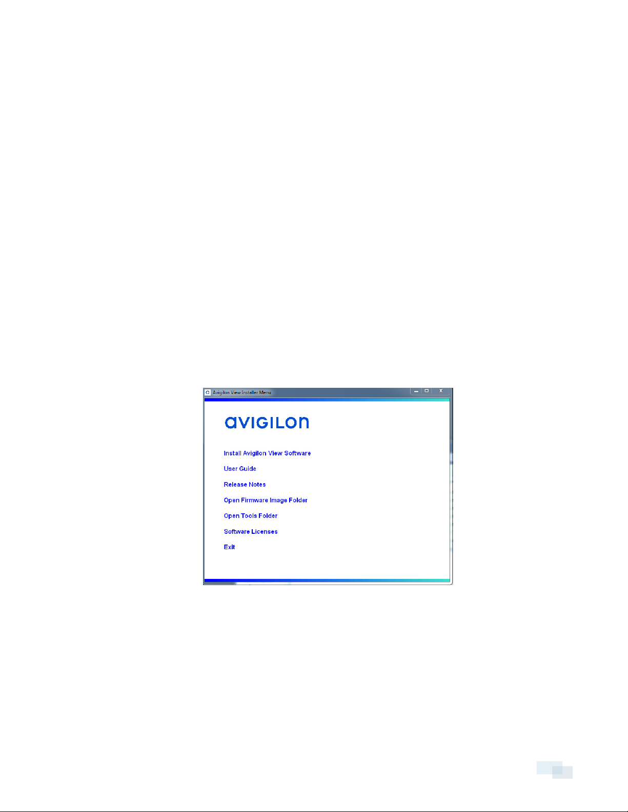
1. Run AvigilonViewInstaller.exe
2. When the installer window appears, click Install Avigilon View Software.
3. Review the License Agreement and accept. If you do not accept the license agreement, the installation is
canceled.
Installation 9
Page 10
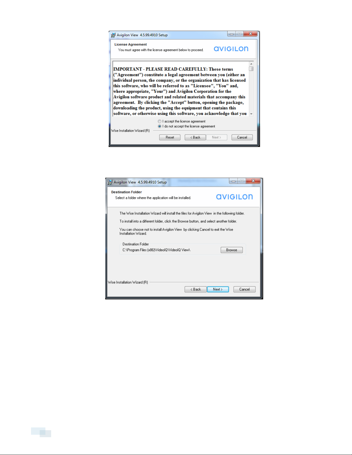
4. Select a new destination folder or keep the default folder and click Next.
NOTE: The View software must be installed on a local drive, not on a network drive.
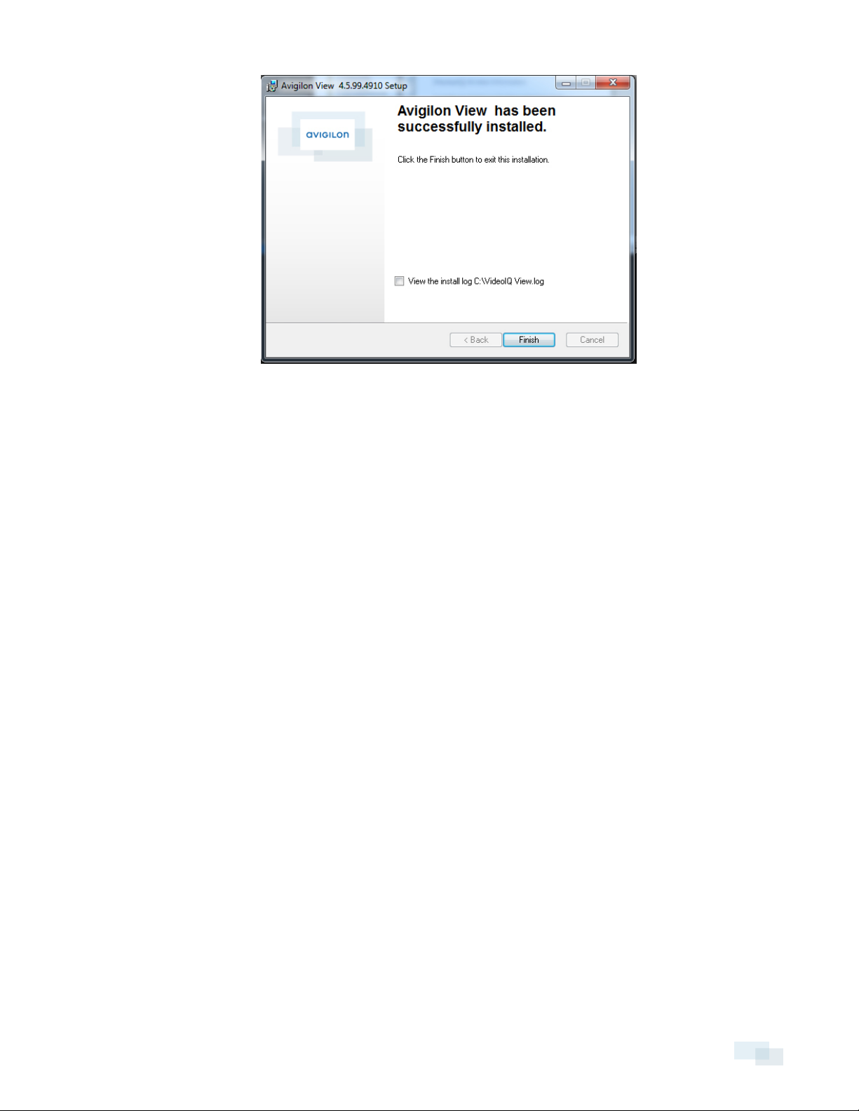
5. When the View software has correctly installed, click Finish.
10 Installing the Avigilon™ View Software
Page 11
Installing the Avigilon™ View Software 11
Page 12

Daily Operations
Users can perform day-to-day operations in the Avigilon™ View software such as acknowledging alarm events
and viewing live video.
NOTE: Some features may not be accessible to all accounts. If you cannot access one or more of the following
features, then your account does not have permission to do so.
l Logging In on the facing page
l Changing Your Account Password on page14
l Camera Trees on page37
l Camera Groups on page38
l Live Video on page16
l IQTrack on page22
l Rules on page25
l Alarm Events on page29
12 DailyOperations
Page 13
Getting Started
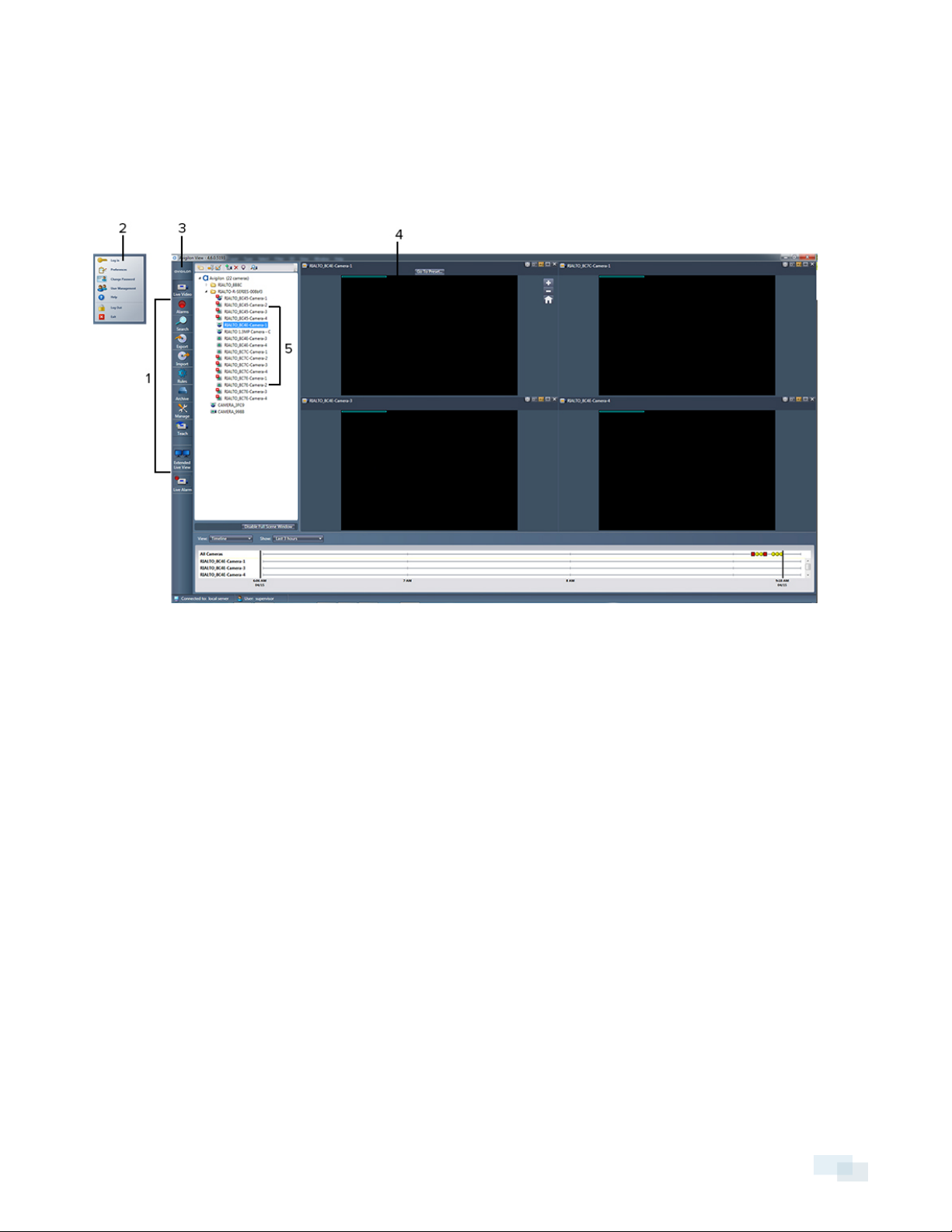
Navigation
# Feature Description
1 Toolbar Allows you to manage your analytic appliances.
2 View menu Allows you to manage accounts and software preferences.
3 Menu button Allows you to access the View menu.
4 Camera window Displays live video image from a camera.
5 Camera tree Lists all attached cameras.
Logging In
Before logging in, ensure you have a valid user account with a username and password. If you do not have one,
contact your supervisor.
1. Run the Avigilon™ View software.
2. Enter your username and password.
Getting Started 13
Page 14
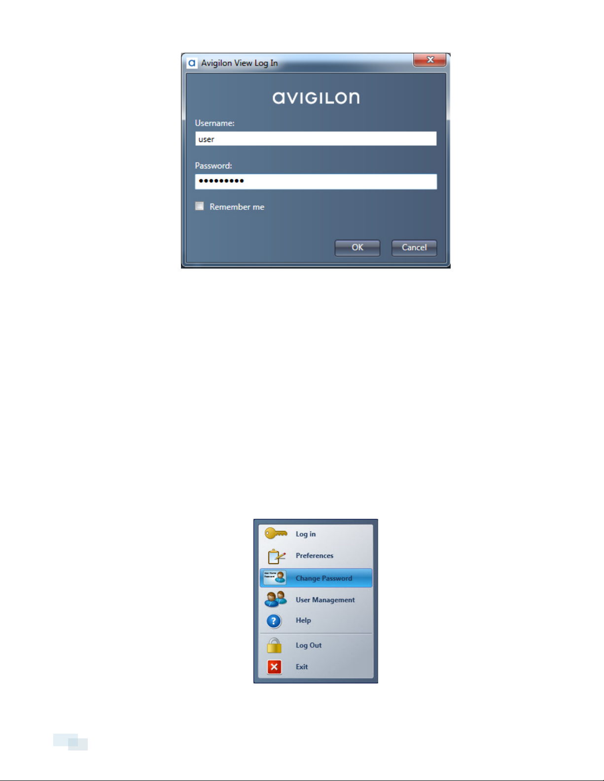
3. If you want the View software to log you in automatically the next time, check the Remember Me box.
4. Click OK.
NOTE: When logging in for the first time, the View software will automatically discover and add all attached
analytic appliances. If the View software doesn't automatically discover and add all analytic appliances, you must
manually activate auto-discovery. To do so, complete the steps in Manually Activating Auto-Discovery on
page37.
Changing Your Account Password
Once you have logged into your account, you can change your password. You cannot change your username.
NOTE: Each password is connected to a particular analytic appliance. If you change a password for your account
on a single analytic appliance, you can access that analytic appliance only by logging into your account using
that password. A single account can have multiple passwords, each used to access a specific analytic appliance.
1. Open the View menu and select Change Password.
14 Changing Your Account Password
Page 15
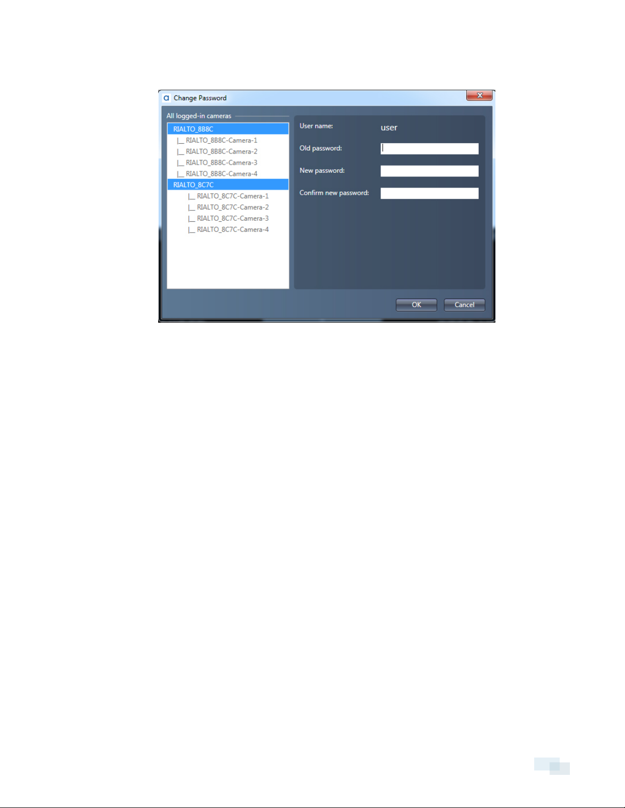
2. Select the analytic appliance where you to want to change the password. Hold Ctrl to select multiple
analytic appliances.
3. Enter your old password.
4. Enter your new password.
NOTE: Password must be a minimum of 4 characters and is case sensitive.
5. Enter your new password again to confirm it.
6. Click OK.
Changing Your Account Password 15
Page 16
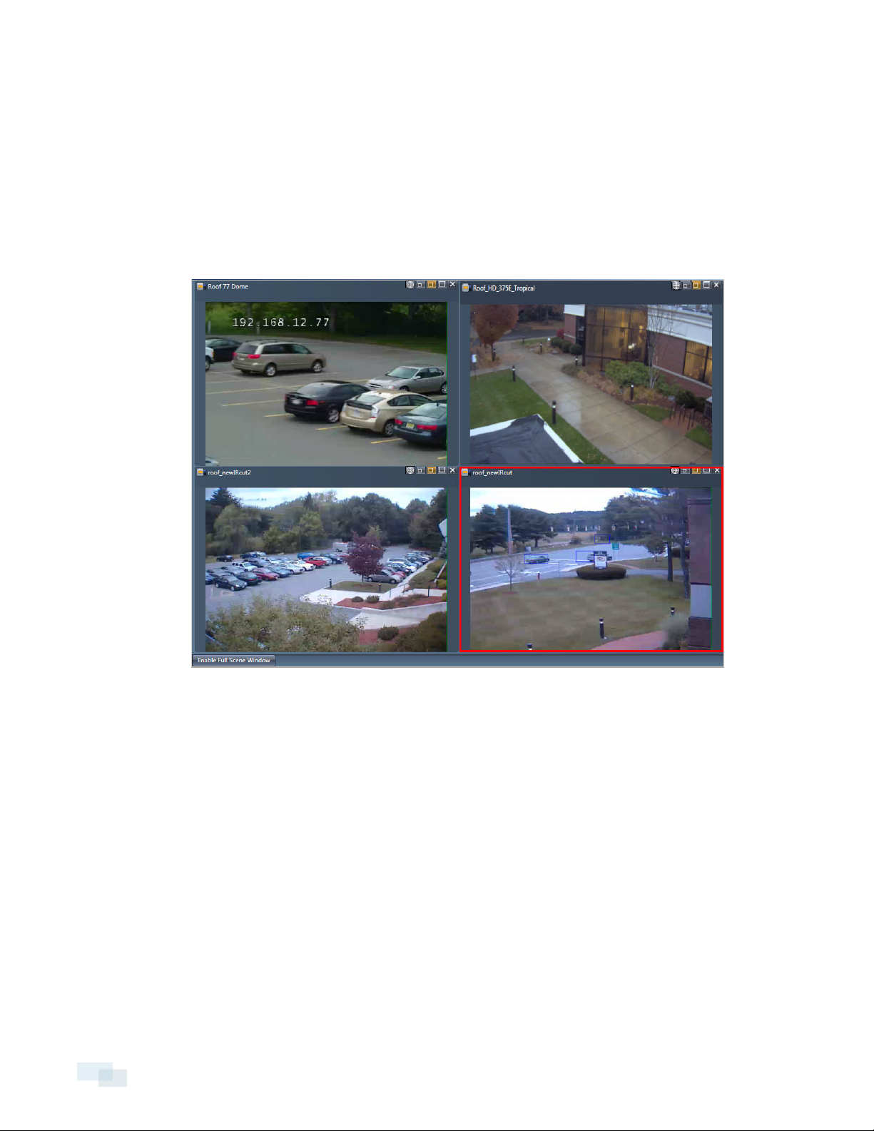
Live Video
The Live Video area is where you can view live video from your cameras. You can add and display a single
camera window at full resolution, up to 4 medium-sized camera windows, or up to 16 small-sized camera
windows in the Live Video area. Each live video can be zoomed in or out.
Setting Video Quality
By default, the View software will stream video image at a lower resolution and bandwidth in the medium and
small windows, and at a higher resolution and bandwidth for the large window. If you want to use the highest
quality video stream in all windows or the lower resolution stream in the large window, you can set the View
software to do so.
NOTE: You can only enable high quality video stream for medium-sized and large-sized camera windows, not
small-sized camera windows.
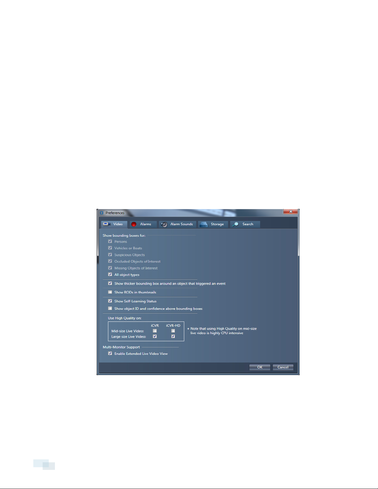
1. Open the View menu and select Preferences.
2. Click the Video tab.
3. Perform one of the following options:
l To enable high quality for all windows, check the Mid-size Live Video and Large size Live Video
boxes.
l To enable low bandwidth for large windows, uncheck the Large size Live Video box.
4. Click OK.
16 LiveVideo
Page 17
Enabling Multi-Monitor Support
You can set the View software to support 2 monitors in order to view live video from up to 32 cameras.
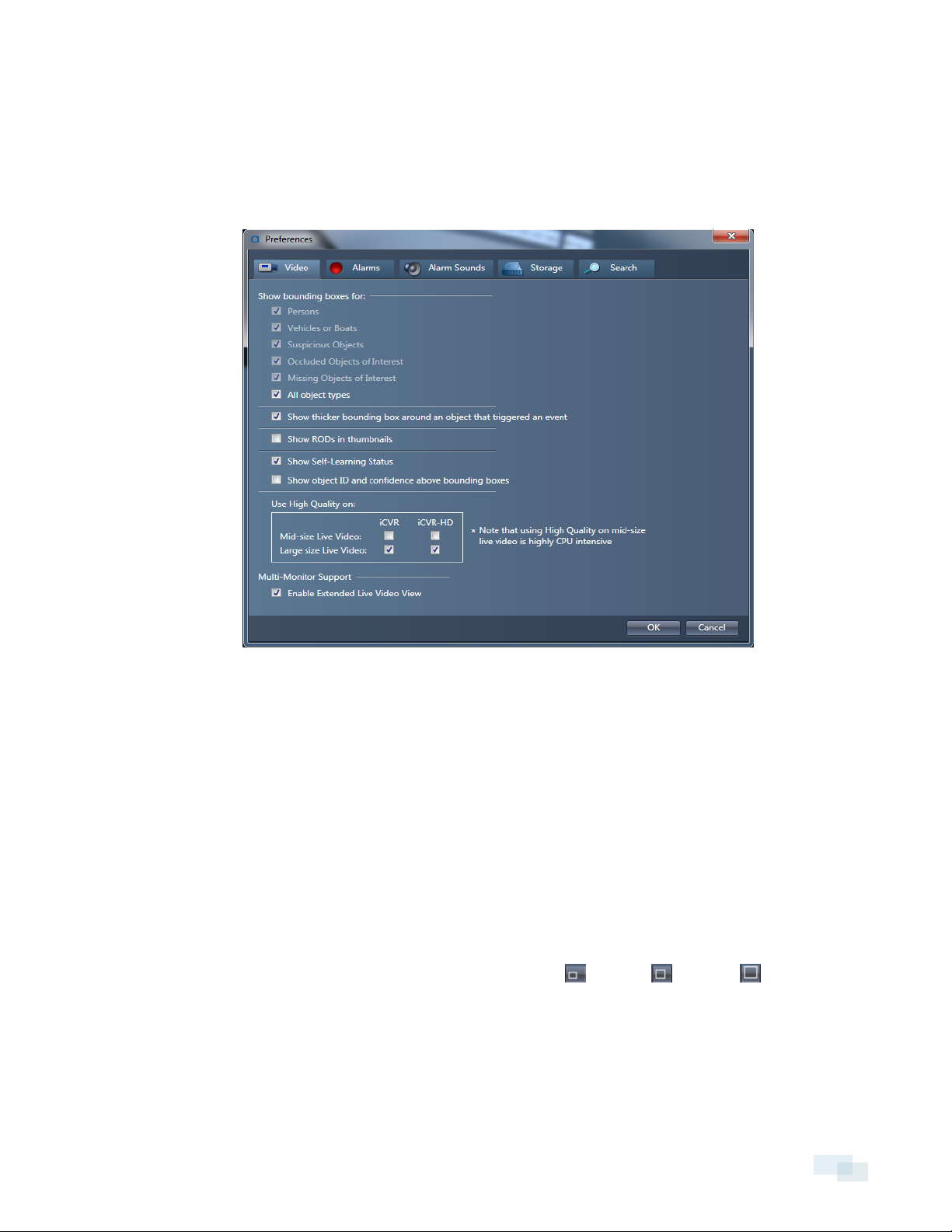
1. Open the View menu and select Preferences.
2. Click the Video tab.
3. Under Multi-Monitor Support, check the Enable Extended Live Video View box.
4. Click OK.
5. Click the Extended Live Video tool to begin viewing Live Video on 2 monitors.
Viewing Live Video
1. Click the Live Video tool.
2. To add a camera window to the Live Video area, perform one of the following actions:
l Double-click a camera in the camera tree.
l Drag a camera from the camera tree into the Live Video area.
3. You can adjust the camera windows in the following ways:
l
To change the size of a camera window, click the Small , Medium , or Large icons in the
upper right corner of the window.
l To rearrange camera windows, drag each window into different positions in the Live Video area.
NOTE: While viewing video, colored bounding boxes indicating different object types will display on the screen.
You can choose to show or hide these bounding boxes. To do so, complete the steps in Show or Hide Bounding
Boxes on the next page.
Enabling Multi-Monitor Support 17
Page 18
Viewing Live Video Across Two Monitors
You can view live video across 2 monitors using the Extended Live Video tool.
NOTE: If you cannot see the Extended Live Video tool on the toolbar, make sure that you have the View
software set to support multiple monitors. See Enabling Multi-Monitor Support on the previous page.
1. Click the Extended Live View tool.
2. Select the analytic appliances or camera groups you want to add and drag them to the Extended Live
Video window.
NOTE: A video window cannot display on both the main View software window and on the Extended Live Video
window.
Show or Hide Bounding Boxes
Boundingboxes are colored box outlines that help you see the objects detected in your videos. Different color
outlines indicate different types of objects.
l Red outlines designate humans.
l Blue outlines designate vehicles or boats.
l Yellow outlines designate suspicious objects (unclassified objects that look similar to a person or vehicle).
To change the settings for bounding boxes:
1. Open the View menu and select Preferences.
2. Click the Video tab.
18 Viewing Live Video Across Two Monitors
Page 19
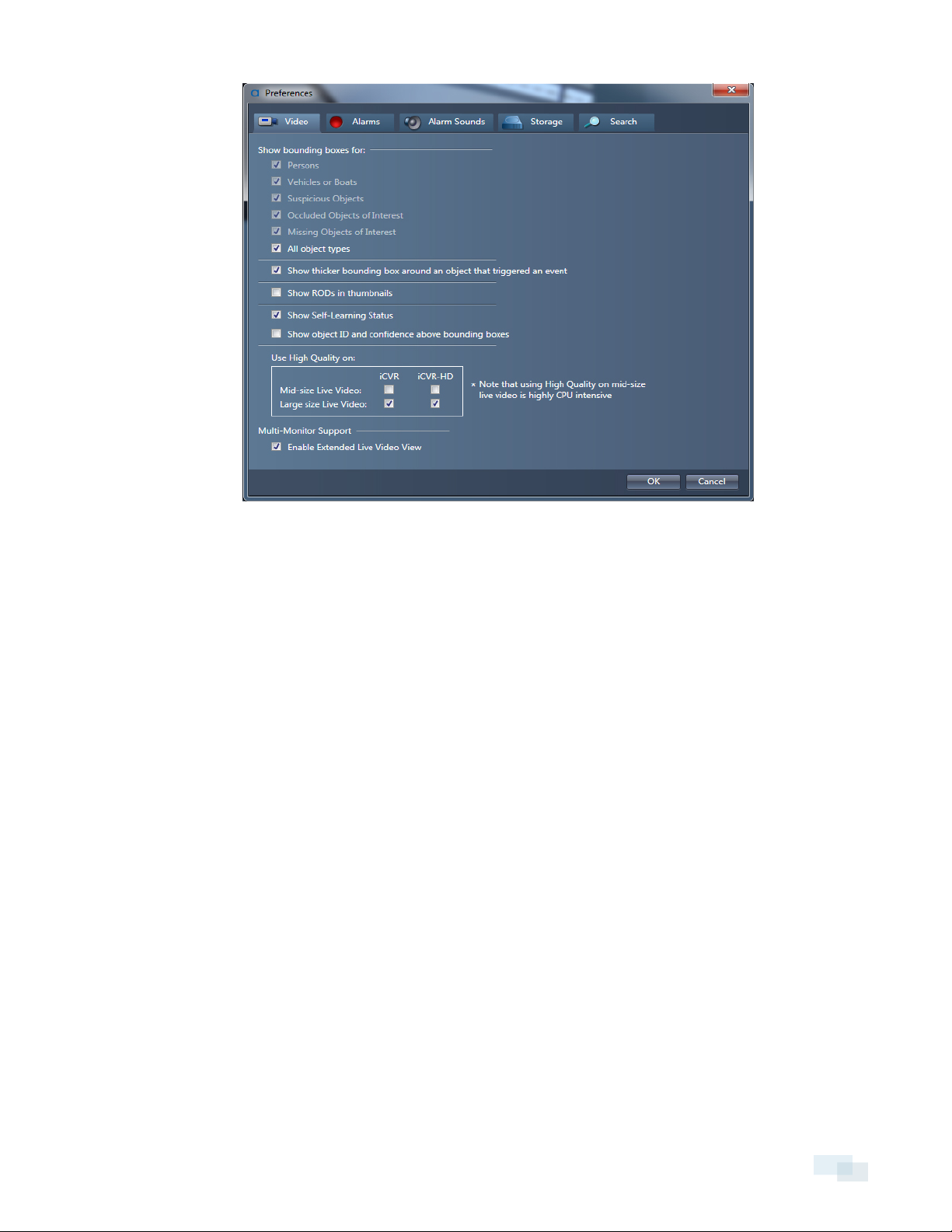
3. Perform one of the following actions:
l To show bounding boxes for individual object types, check each object type box.
l To show bounding boxes for all object types, check the All object types box.
l To hide bounding boxes, uncheck the box for each object type you do not want bounding boxes
to show.
4. To highlight the bounding box around an object that triggered an alarm, check Show thicker bounding
box around an object that triggered an event.
5. To display an object's ID number and its classification confidence, check the Show object ID and
confidence above bounding box box.
6. Click OK.
Zooming In on an Object or Area
Use the zoom controls to quickly zoom in or out on an object or area in a camera window.
NOTE: If you are not using a PTZ camera, the zoom function is a digital zoom that only affects the live video
displayed in the View software. If you are using a PTZ camera, the zoom functional will mechanically zoom the
camera lens.
Zooming In on an Object or Area 19
Page 20
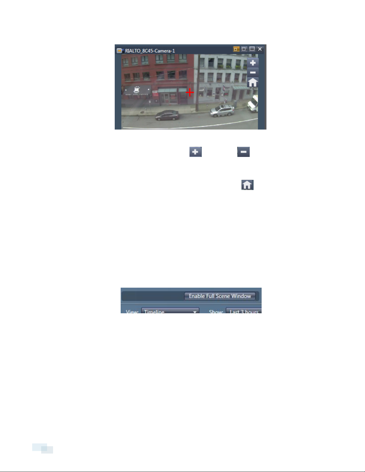
1. Hover your cursor over the Live Video camera window to activate the zoom controls.
2. Perform one the following actions:
l
To zoom in or out, click and hold the Zoom In or Zoom Out buttons, or use the scroll
wheel on your mouse.
l To zoom in on a specific point in the window, double-click the area you want to zoom in on.
l
To return the window to its original magnification, click the Home button.
l To pan to another area while zoomed in, click and drag inside the Live Video camera window.
l To focus the zoom function on a specific point, click once on the area in the window you want to
focus on.
Using Full Scene Window
As you zoom in or out on a Live Video camera window, you can view the original full display as a smaller window
using Full Scene Window.
1. At the bottom of the camera tree, click Enable Full Scene Window.
2. Zoom in on the camera window to activate Full Scene Window display.
3. Use the crop rectangle in Full Scene Window to pan to another area in the Live Video camera window.
20 Using FullScene Window
Page 21
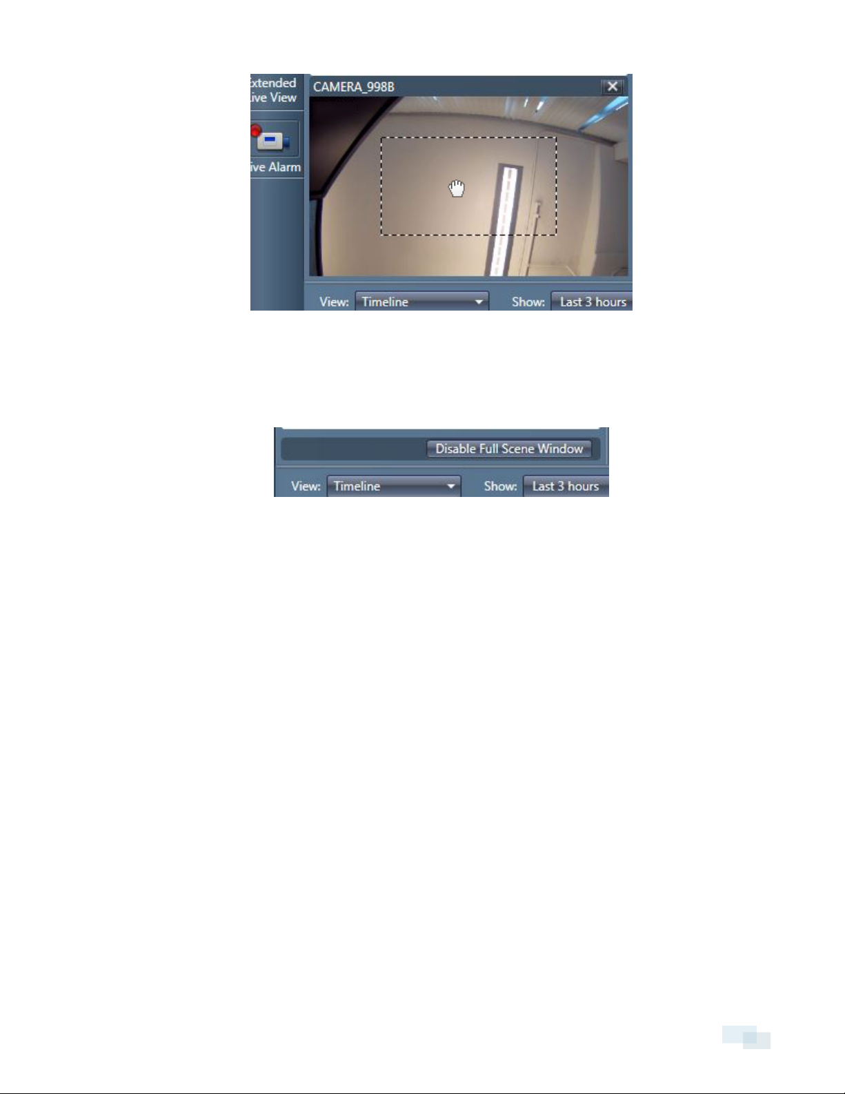
The crop rectangle corresponds to the zoom area in the camera window.
4. To close the Full Scene Window, click the Home button in the camera window.
5. To prevent Full Scene Window from displaying, click the Home button, then click Disable Full Scene
Window.
UsingFull Scene Window 21
Page 22
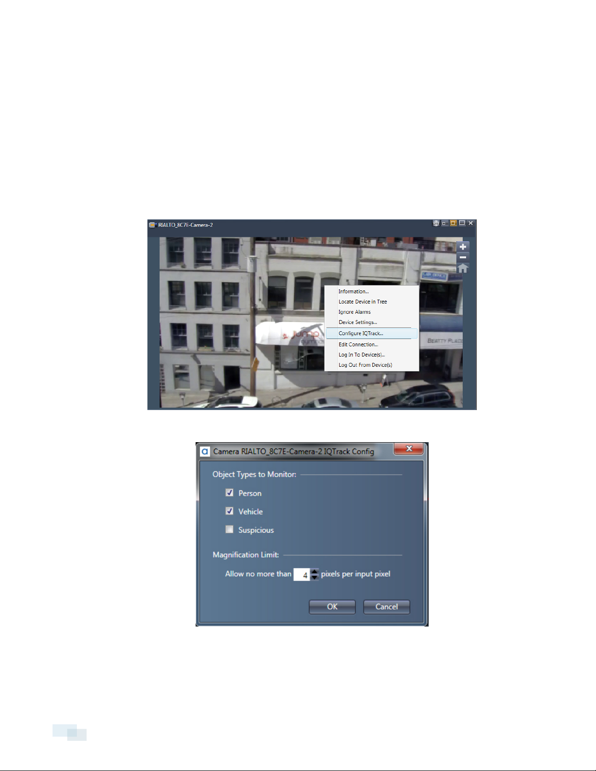
IQTrack
IQTrack allows you to automatically zoom in on and follow an object type in a live video camera window until it
leaves the camera’s field of view. You can set which object types you would like IQTrack to monitor: vehicle,
person, suspicious objects, or all three.
Setting Up IQTrack
1. Right-click on the camera window and select Configure IQTrack.
2. Check the box for each object type you would like to monitor.
3. Set the magnification limit to specify how much the camera will zoom in on the object type.
4. Click OK.
22 IQTrack
Page 23
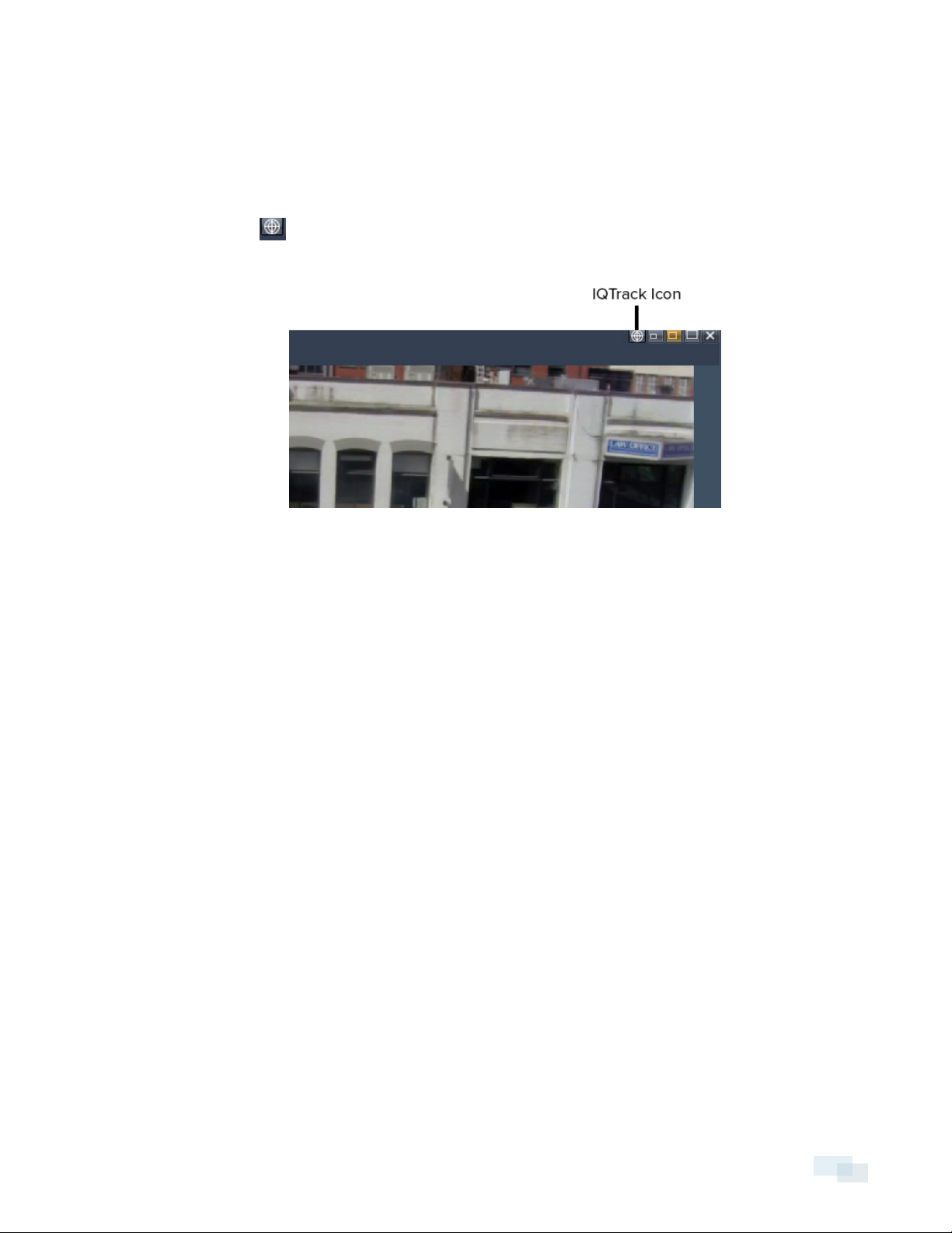
Using IQTrack
Before you begin using IQTrack, you must choose which object types you would like IQTrack to monitor. To do
so, complete the steps in Setting Up IQTrack on the previous page
1. Ensure the camera window is set to medium size or large size.
2.
Click the IQTrack icon in the camera window. The IQTrack icon will not show in small-sized camera
windows.
3.
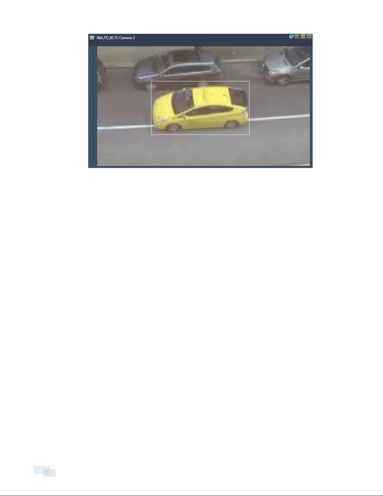
4. The camera will automatically zoom in on the object until it leaves the camera’s field of view.
5. To turn off IQTrack, click the IQTrack icon again.
NOTE: If more than one object of an object type moves into the camera’s field of view, all objects will be
tracked until you choose a specific target to track.
Monitoring a Specific Target with IQTrack
1. Ensure IQTrack has been configured and is enabled.
2. Move your cursor towards the specific target until the bounding box turns orange.
3. Click on the target to select it and begin monitoring.
UsingIQTrack 23
Page 24
4. To deselect the target, click anywhere outside of the bounding box.
24 Monitoring a SpecificTarget with IQTrack
Page 25

Rules
What are Rules?
Rules can be set for each camera. They are used to define:
l The types of objects the camera should monitor.
l The regions, objects, and directions of travel the camera should monitor.
l The actions a camera should take when a rule is triggered.
When a rule is triggered, it results in an alarm event. You can view the rules on each camera and their details,
such as the name of the rule, whether or not the rule is enabled, and the action taken when the rule is triggered.
NOTE: Unless your account has been granted permission, you cannot create, edit, or delete rules.
Regions of Interest, Regions of Disinterest, and Beams
Arule can use Regions of Interest (ROI), Regions of Disinterest (ROD), and Beams to determine what will cause an
alarm event to trigger.
l Regions of Interest: The areas of a scene where activity is detected.
l Regions of Disinterest: Used to mark areas within an ROI where false alarms occur frequently. Areas
marked as a ROD will not trigger an alarm when the activity detected in the ROInormally would.
l Beams: Virtual lines used to detect when an object crosses a specified beam, such as a person walking
through a gate.
If a rule contains an ROI or Beam, it will be marked on the camera window thumbnail in the rule summary. To
access a rule summary, complete the steps in Viewing Rules below.
NOTE: Regions of Disinterest will not be marked unless it is enabled in Preferences. To do so, complete the
steps in Enabling Regions of Disinterest (ROD) in Thumbnails on page27.
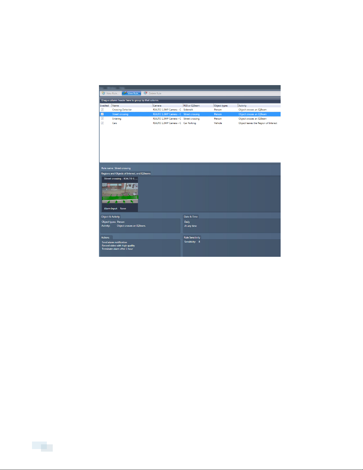
Viewing Rules
Each camera has one or more rules defined in order for an alarm event to trigger when the rule is violated. You
can view the rules set for each camera, as well as the details for that particular rule.
1. Click the Rules tool.
2. Select a camera from the camera tree to view a list of the rules set for that camera.
3. Select a rule from the list to access a summary of the rule that informs you:
l The name of the rule.
l What Region of Interest, Region of Disinterest, Object of Interest, or Beams have been configured.
Rules 25
Page 26
NOTE: You must enable show RODin thumbnails to see any RODs configured. To do so, complete
the steps in Enabling Regions of Disinterest (ROD) in Thumbnails on the facing page.
l The object type and activity set for detection.
l What day and time the rule is active.
l What action is initiated when the rule is violated and an alarm event is triggered.
4. To view the rule in further detail, click View Rule....
5. In the View Rule window, you can:
l Explore what settings are configured in the Activity, Cameras, Date/Time, and Actions tab.
l Access the rule summary similar to the version available in the main Rules window.
26 Viewing Rules
Page 27
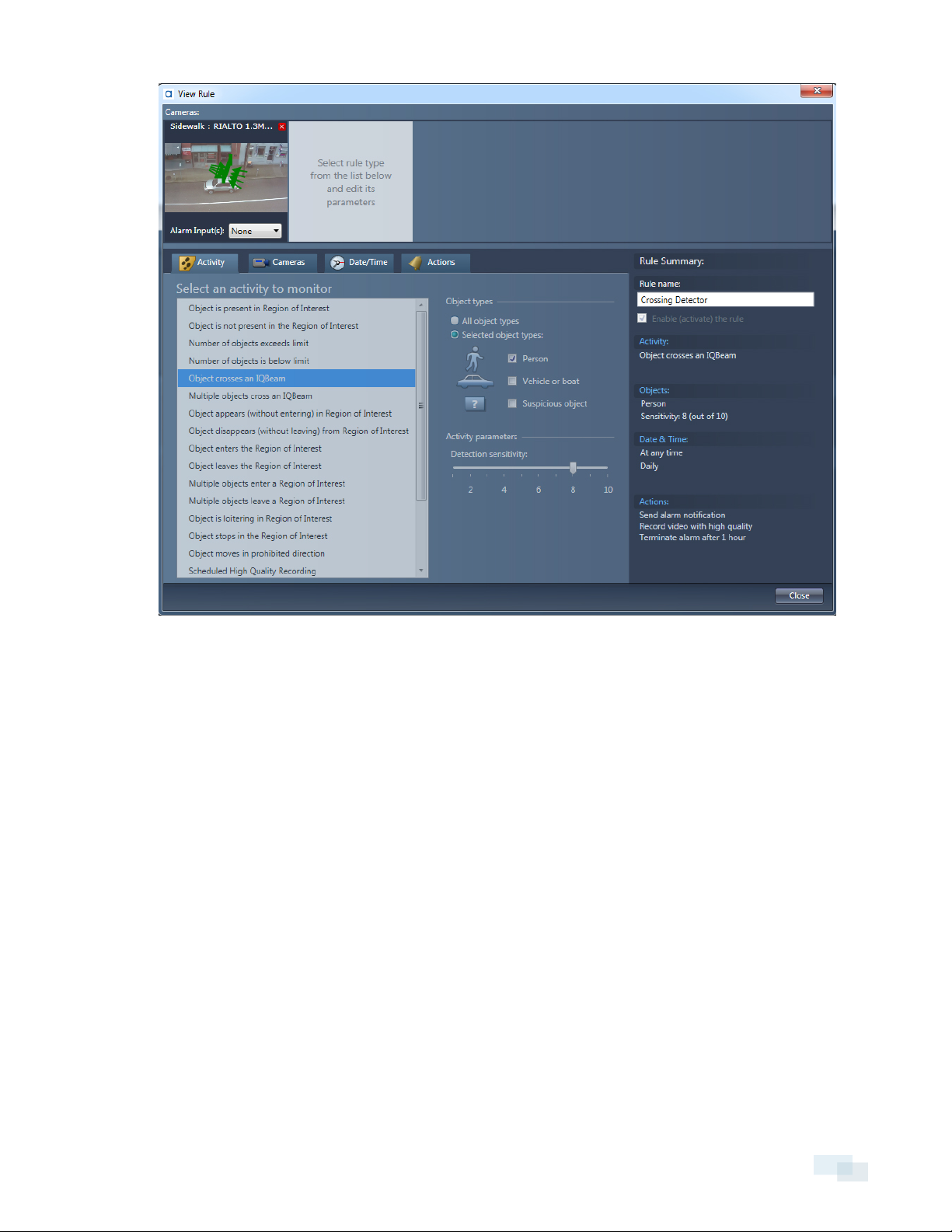
NOTE: You cannot edit any settings in the View Rule window, including enabling or disabling a rule. You can only
view the settings that have already been configured.
Enabling Regions of Disinterest (ROD) in Thumbnails
Regions of Disinterest indicate areas within a Region of Interest where activity will not trigger an alarm. By
default, RODs are not marked on the camera window thumbnail in the rule summary. You must enable RODs to
show to see them on the thumbnail.
1. Open the View menu and select Preferences.
2. Click the Video tab.
Enabling Regions of Disinterest (ROD) in Thumbnails 27
Page 28

3. Check the Show RODs in thumbnails box.
4. Click OK.
28 Enabling Regions of Disinterest (ROD) in Thumbnails
Page 29
Alarm Events
Alarm events occur when a rule is triggered. When an alarm event occurs, you can access the alarm clip to
review it and acknowledge the alarm event.
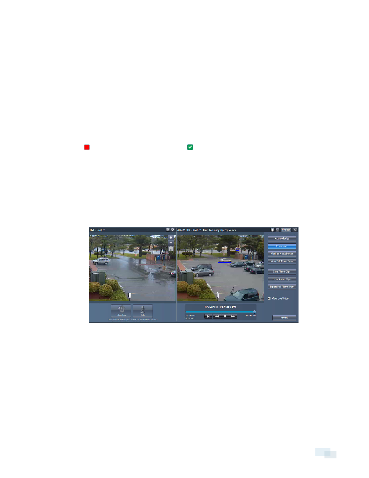
Reviewing and Acknowledging Alarm Events
You must review an alarm event in the playback window before you can acknowledge it. In the playback
window, you can also comment, save, and email the alarm event.
Acknowledging an alarm will make the alarm sound stop. Acknowledged alarms will change their display icon
from a red square to a green square with a check mark .
NOTE: If two or more users are logged into the same analytic appliance, the alarm event will display as
acknowledged as soon as one user acknowledges the alarm.
Adding a Comment to an Alarm Event
While marking an alarm event as false or acknowledging an alarm event, you can also add comments.
1. Select and open an event from the alarm list.
2. Click Comment.
3. Enter your comment.
Alarm Events 29
Page 30
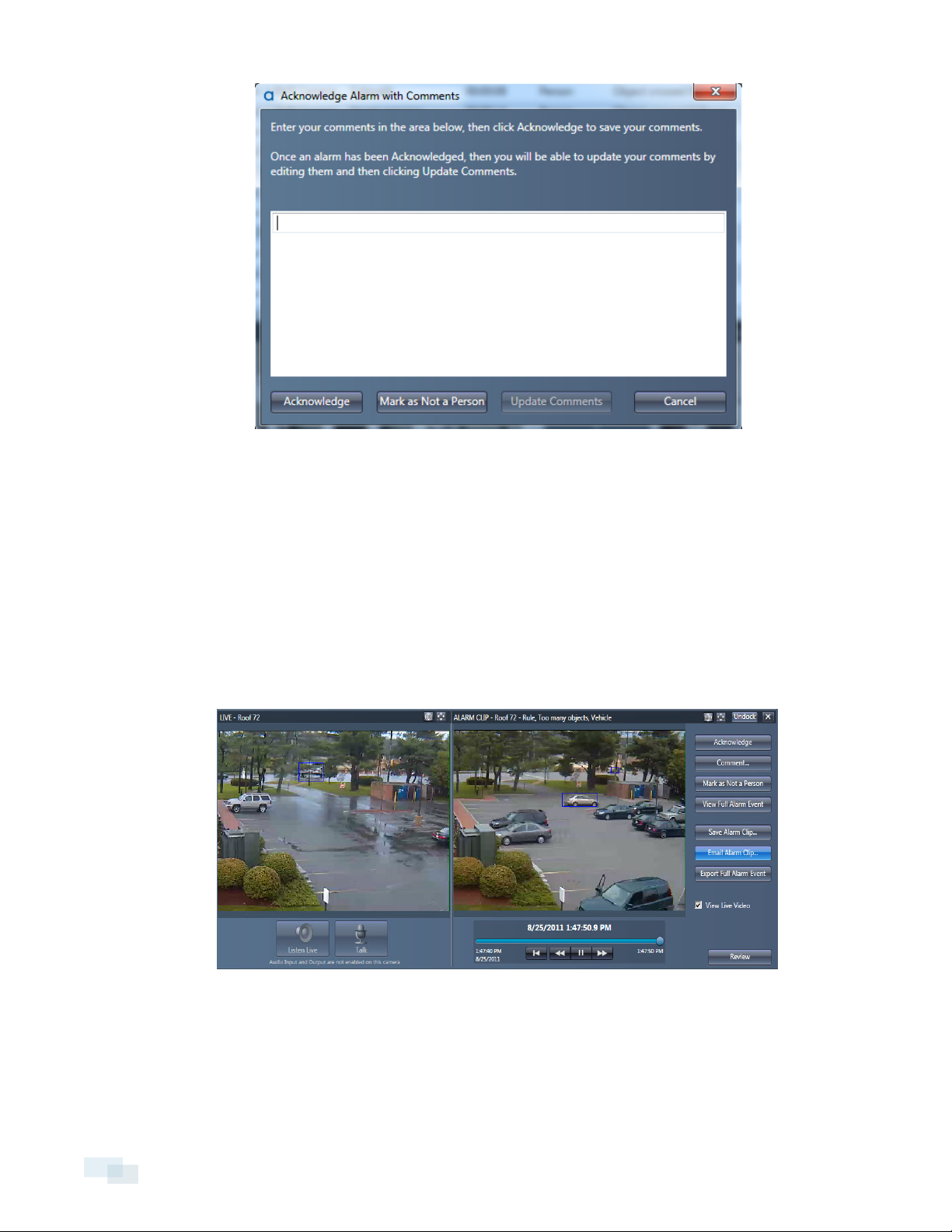
4. Save your comment with one of the following procedures:
l Click Acknowledge to acknowledge the alarm and save the comment.
l Click Update Comment if the alarm has already been acknowledged.
Emailing Alarm Clips
You can email an alarm clip directly from the Avigilon™ View software. Make sure that the recipient has a video
player application that can play .mp4 files.
1. Open your email application.
2. Select and open an event from the alarm list.
3. Click Email Alarm Clip.
4. In your email application, enter the email address of the person receiving the alarm clip and send the
message. The clip will be automatically added as an .mp4 attachment to the email message.
NOTE: Bounding boxes will not show in alarm clips viewed outside of the View software unless the Media
Components plug-in is installed. You can download the plug-in from the Avigilon support website.
30 Emailing Alarm Clips
Page 31

Saving Alarm Clips to a Hard Drive
You can save alarm clips to a location outside of the analytic appliance.
1. Select and open an event from the alarm list.
2. Click Save Alarm Clip.
3. Navigate to the directory where you want to save your clips.
4. Click Save.
NOTE: You can also set the View software to download all alarm events that occur. To do so, complete the
steps in Automatically Download Alarm Video Clips on page34.
Viewing Alarm Events While Using Live Video
You can also see alarm events while in the Live Video area. Alarm events are displayed in timeline, a list, or in
the alarming cameras view. From here, you can review each alarm event and manage it through the playback
window.
List View
In List view, alarms are displayed as a list in chronological order.
1. At the bottom of the Live Video window, use theView drop-down menu and select List.
2. Use the Show drop-down menu to specify the time period of events to display.
3. Select an alarm event in the list and double click to show the video clip.
Saving Alarm Clips to a Hard Drive 31
Page 32

Alarming Cameras View
In the Alarming Cameras view, alarm event windows are added and displayed in a panel. Up to four alarm event
windows can be displayed at one time.
NOTE: To access Alarming Cameras from the View drop-down menu, you must first enable Live Alarms. See
Enable Live Video Pop-up Upon an Alarm Event on page34.
1. At the bottom of the Live Video window, use theView drop-down menu and select Alarming Cameras.
2. As each new alarm event occurs, a window of the previous event is added to the panel.
l To immediately add a Live Alarm Pop-up window to the panel, click the Close button.
l To open an alarm event as aLive Alarm Pop-up window, click the Maximize button.
Timeline View
In Timeline view, alarms are displayed using icons to indicate the type of event. See In the Timeline view, the
status of each alarm event is indicated by the following symbols: on the facing page.
1. At the bottom of the Live Video window, use theView drop-down menu and select Timeline.
2. Use the Show drop-down menu to specify the time period of events to display.
3. Click on the icon of the alarm event you wish to view.
4. If you click a multiple alarms event, find the specific alarm event you wish to view in the Select Alarm
window.
32 Alarming Cameras View
Page 33

5. Highlight the alarm event and click Review.
Understanding the Timeline View
In the Timeline view, the status of each alarm event is indicated by the following symbols:
Alarm Icon Description
Indicates a single alarm event.
Indicates multiple alarm events.
Indicates a system event.
Indicates a camera has been disconnected.
Automatically Acknowledge Alarms
You can set alarms to be automatically acknowledged as soon as you review the alarm event.
1.1. Open the View menu and select Preferences.
2. Click the Alarms tab.
2. Check the Automatically acknowledge alarms upon review box.
3. Click OK.
AutomaticallyAcknowledge Alarms 33
Page 34

Enable Live Video Pop-up Upon an Alarm Event
You can set the View software to pop up a live video of the camera when an alarm event happens.
1.1. Open the View menu and select Preferences.
2. Click the Alarms tab.
2. Check the box for live-video pop up when an alarm occurs.
3. Set the number of seconds you want to keep the Live Alarm Pop-up window open.
4. Click OK.
5. In the toolbar, click the Live Alarm tool to enable the feature.
Automatically Download Alarm Video Clips
You can automatically download alarm video clips as soon as an alarm event occurs.
1.1. Open the View menu and select Preferences.
2. Click the Alarms tab.
2. Under Clip Download, check the Download alarm clips box.
3. Set the number of seconds before the video clip stops downloading.
4. Click OK.
34 Enable LiveVideo Pop-up Upon an Alarm Event
Page 35

Enabling Alarm Sounds
By default, alarm sounds are disabled. You can enable an alarm sound to play for each type of rule.
1. Open the View menu and select Preferences.
2. Click the Alarm Sounds tab.
3. Check the Play Sound box beside the rule type (Alarm Activity)that you want to play a sound.
4. Click OK.
Customizing Alarm Sounds
You can change the default sound that plays for each alarm activity by uploading your own sound files.
NOTE: Only .WAV files are supported as sound files.
1. Open the View menu and select Preferences.
2. Click the Alarm Sounds tab.
Enabling Alarm Sounds 35
Page 36

3. Select the alarm activity with the sound you want to change.
4. Click Browse.
5. Select a new sound file and click Open.
6. Click OK.
36 Customizing Alarm Sounds
Page 37

Camera Trees
All Rialto™ analytic appliances and attached cameras are displayed in the camera tree once they have been
added by the Avigilon™ View software.
Analytic appliances display as a folder in the tree. You can see what cameras are attached to the analytic
appliance by expanding the folder.
NOTE: Analytic appliances are automatically added to the View software upon logging in. If they are not added
upon logging in, you must activate the auto-discovery manually. To do so, complete the steps in Manually
Activating Auto-Discovery below
Manually Activating Auto-Discovery
If not all analytic appliances have been discovered and added to the camera tree, you can activate the autodiscovery feature manually.
NOTE: Automatic discovery can only find analytic appliances attached to the same local area network (LAN) as
your monitoring workstation. If you want to add an analytic appliance on a different or remote network, you must
do so manually using the analytic appliance's IP address and port information.
1.
Click the button in the camera tree toolbar.
2. The View software will automatically find the cameras and analytic appliances, and add them to the tree.
Understanding Camera Tree Icons
The state of the camera is shown using the icons below:
Icon Description
Camera is connected.
Camera is not accessible
PTZ camera is connected.
PTZ camera is disconnected and is not accessible
Camera is disconnected.
Camera Trees 37
Page 38

Icon Description
Camera is online, but cannot accept more connections.
Incorrect login.
Camera firmware needs update.
A rule has been violated.
Encoder signal is lost.
System alarm.
Camera is still starting up or upgrading. May also mean a hard disk failure.
Sub-camera is connected.
Sub-camera is not accessible.
Folder in camera tree.
Open folder in camera tree.
Firmware too new for camera.
Camera Groups
You can create camera groups to organize your cameras or to easily apply the same settings to all cameras in
the group. You can create as many camera groups as you like.
NOTE: Moving a camera into a camera group does not detach it from the analytic appliance. Camera groups only
visually organize your cameras.
38 Camera Groups
Page 39

Creating a Camera Group
1. Select the topmost level in the camera tree.
2.
Right-click and select New Group or click the button.
3. Enter the name of the new camera group.
4. Add cameras to the new camera group by dragging and dropping cameras in the tree into the camera
group folder.
NOTE: A camera can belong to only one camera group.
Renaming a Camera Group
NOTE: You can only rename a camera group you created. Camera groups you didn't create can only be
renamed if you have permission to do so.
1. Right-click on the camera or camera group and select Rename.
2. Enter the new name for your camera or camera group.
3. Press Enter to accept the new name.
Deleting a Camera Group
NOTE: Deleting a camera group only removes the group folder. It does not delete the cameras from the camera
tree.
1. Select the camera group folder you want to delete.
2. Right-click on the camera group and select Delete.
Finding Cameras or Camera Groups in the Camera Tree
You can quickly find a camera or camera group in the camera tree using the Locate Device tool.
1.
Click the button.
2. In the Locate by drop-down menu, select whether you want to locate by Name, IP Address, or MAC
Address.
Creating a Camer a Group 39
Page 40

3. Enter the name of the camera or camera group you’re searching for.
4. Click Locate to show your search results.
5. Click on the camera or camera group you want to locate to show its position in the camera tree. The
camera or camera group will blink green and yellow.
Displaying Camera Information
You can see a camera's information details, including camera name, device type, IP address, port settings, and
firmware version.
40 Displaying Camera Information
Page 41

1. Right-click the camera in the camera tree and select Information....
2. Click Close when you are finished reviewing the information.
Displaying Camera Information 41
Page 42

Advanced Settings and Operations
If you have a supervisor-level account or you're an operator with the proper permissions enabled, you can
access advanced settings and operations in the Avigilon™ View software such as creating and editing rules,
managing other user accounts, and configuring settings for analytic appliances.
NOTE: Supervisor-level accounts have all permissions enabled by default and can access all features in the View
software.
You can access the following advanced settings and operations:
l Account Management on the facing page
l Managing Rialto™ Analytic Appliances on page51
l Creating and Editing Rules on page54
l Alarms on page71
l Teach By Example on page77
l Archiving on page83
l Performing a Search on page85
l Configuring Settings for a Rialto™ Analytic Appliance on page90
42 Advanced Settings and Operations
Page 43

Account Management
You can manage both your own account and other user accounts, such as changing user passwords and editing
permissions that the user account has.
Logging In for the First Time
If you are logging in for the first time for setup, each analytic appliance has two default accounts. Use the
supervisor account if you will be setting up the Avigilon™ View software and analytic appliances.
Username Password
supervisor supervisor
operator operator
NOTE: The default supervisor account should not be used for day-to-day activities. Users with supervisor-level
accounts should have their own username and password so that history logs will identify who made changes to
the system.
Adding a User Account
You can add as many user accounts as you like to an analytic appliance.
1. Open the View menu and select User Management.
2. Enter your password and click OK to confirm your credentials.
3. Select the analytic appliance to which you want to add a user account.
4. Click New User....
Account Management 43
Page 44

5. Set the account type as Supervisor or Operator.
6. Enter a username and the user's full name.
7. Enter a password for the user account.
NOTE: Password must be a minimum of 4 characters and is case sensitive.
8. Enter the password again to confirm it.
9. Click OK.
Editing a User Account
You can change the password and user type of an account once it is created.
44 Editing a User Account
Page 45

1. Open the View menu and select User Management.
2. Enter your password and click OK to confirm your credentials.
3. Select a user and click the Edit User button.
4. Change the User Type, Full name, or Password.
5. Click OK.
Setting User Permissions
You can change the permissions for all operator-level user accounts. When you make a change, it applies to all
users on the selected analytic appliance with the operator rule.
Setting User Permissions 45
Page 46

NOTE: Permissions can only be set for operator-level accounts. Supervisor-level accounts are granted access to
all features in the View software by default.
1. Open the View menu and select User Management.
2. Enter your password and click OK to confirm your credentials.
3. Click User Groups and select Operators.
4. Select the analytic appliance that has the permissions you want to change.
5. Click Edit Operator Permissions.
46 Setting User Permissions
Page 47

6. Check the boxes beside the permissions you want to enable. For a list of permissions and their
descriptions, consult Available User Permissions on page125.
7. Click Apply Permssions.
Copying Account Settings and Permissions
You can copy the user account settings and permissions from one analytic appliance to another.
1. Open the View menu and select User Management.
2. Enter your password and click OK to confirm your credentials.
3. Select the analytic appliance that has the accounts you want to copy, then click Copy User Accounts....
Copying Account Settings and Permissions 47
Page 48

4. Select one or more analytic appliances that you want to copy the accounts to.
5. Choose whether you want to overwrite the old accounts or merge new accounts while keeping the old
accounts and click one of the following:
l Copy Users: Copies only the usernames and passwords.
l Copy Permissions: Copies only the user account's permissions.
l Copy All: Copies usernames, passwords, and permissions.
6. Click Done.
Deleting a User Account
You can delete any user account, except for the default supervisor account.
48 Deleting a User Account
Page 49

1. Open the View menu and select User Management.
2. Enter your password and click OK to confirm your credentials.
3. Select the analytic appliance you want to delete the user account from.
4. In the User Management window, select the user you want to delete.
5. Click Remove.
NOTE: You won't be prompted to confirm the deletion. Make sure you're certain you want to delete the account
before clicking Remove.
Viewing Logged In Users
You can see which users are currently logged into an analytic appliance.
1. Right-click on the analytic appliance in the camera tree and select Review User Connections....
2. In the Current User Connections window, you can see the list of users connected to the analytic
appliance.
Viewing Logged In Users 49
Page 50

3. From this window, you can perform the following actions:
l To refresh the list, click Refresh.
l To disconnect one or more users:
a. Check the box under Terminate to the left of the login name you want to disconnect.
b. Click Terminate Connections.
Force Login
If the login limit has been reached on an analytic appliance, you can log in with Force Login and disconnect one
or more users.
NOTE: Supervisor-level accounts and operator-level accounts with the relevant permissions enabled can use
Force Login.
1. Right-click on the analytic appliance in the camera tree and choose Force Login....
2. Check the box next to the user(s) you want to disconnect.
3. Click Terminate Connections.
50 Force Login
Page 51

Managing Rialto™ Analytic Appliances
Editing Analytic Appliance Connections
You can edit the IP address or Network name, port numbers, and stream type for an analytic appliance.
NOTE: Editing a connection for the analytic appliance affects all attached sub-cameras.
1. Select the analytic appliance in the camera tree.
2. Right-click on the analytic appliance and select Edit Connection....
3. Make your changes and click OK.
Renaming an Analytic Appliance or Camera
You can rename an analytic appliance or any of its attached sub-cameras.
1. Right-click the analytic appliance or camera you want to rename and select Rename.
2. Enter a new name for the analytic appliance or camera.
3. Press Enter to accept the new name.
Filtering IPAddress Communication
You can control what IP addresses can communicate with an analytic appliance.
1. Right-click a camera in the camera tree and select Device Settings...
2. In the Configure Device window, click Network.
Managing Rialto™ Analytic Appliances 51
Page 52

3. Click Advanced Network Settings.
4. Check the Enable IP address filtering box.
5. In the Allow addresses field, enter the IP address you would like to allow communication with the analytic
appliance.
6. Click Apply.
The analytic appliance will now communicate only with the IP addresses entered.
Deleting an Analytic Appliance from the Camera Tree
You can delete an analytic appliance from the camera tree.Deleting an analytic appliance will delete all
attached sub-cameras.
NOTE: Deleting an analytic appliance only removes it from the camera tree. It does not detach it. Once you’ve
deleted an analytic appliance, it won’t be available again until you add it or it’s automatically discovered.
1. Right-click on the analytic appliance you want to delete and select Delete
2. ClickOK to confirm the deletion.
Exporting the Camera Tree
When you have more than one computer running the View software, you can export the camera tree from one
computer to another. Exporting a tree saves the analytic appliance, camera groups, and all connection
information into a file.
1. At the top of the camera tree, right-click on Avigilon.
2. Select Export Camera Tree...
52 Deleting an Analytic Appliance from the Camera Tree
Page 53

3. Navigate to where you want to store the file and save it to begin exporting.
Importing the Camera Tree
If you have a saved file of the exported camera tree, you can use it to import the tree's analytic appliances,
camera groups, and connection information to another computer running the View software. To export a camera
tree, see Exporting the Camera Tree on the previous page.
1. At the top of the camera tree, right-click on Avigilon and select Import Camera Tree...
2. Select the saved exported file and open the file.
3. Read the warning dialogue box. Click Yes to continue with the import.
Once the camera tree has been imported, all analytic appliances will automatically reconnect.
Importing the Camera Tree 53
Page 54

Creating and Editing Rules
When you receive your analytic appliance, it is configured with two default rules. These rules trigger an alarm that
will record the event in high quality. The two default rules are:
l When any people, vehicles or boats are detected entering the camera's full field of view.
l Sudden scene changes.
Rules work together with Regions of Interest (ROI), Regions of Disinterest (ROD), and Beams to detect activity.
See Regions of Interest, Regions of Disinterest, and Beams on page25
Creating a New Rule
1. Click the Rules tool.
2. Click New Rule...
3. Enter a name in for the new rule.
54 Creating and Editing Rules
Page 55

4. Ensure the Enable (activate) the rule box is checked to make the rule active upon creation.
5. Select the type of activity you want to create a rule for. Depending on the rule selected, you may be
prompted to enter one or more activity parameters.
6. Click the Cameras tab and select the camera(s) or camera group(s) that will be using the new rule.
Creating a New Rule 55
Page 56

NOTE: Not all activities are available on all cameras. If your camera does not support a specific activity,
the camera will be grayed out in the camera tree and you will not be able to select it.
7. Perform one of the following procedures:
l If the rule requires a Region of Interest or Beam, select the ROI or Beam to be associated with the
camera. Ensure the camera tree is fully expanded if the list of available options is not visible.
o
If there are no options to use, you need to set up a new ROIor Beam. To do so, complete
the steps in Creating Regions of Interest and Beams on page58.
l If the rule does not require a Region of Interest or Beam, select the camera you want to use the
rule.
8. Click the >> button to add the selections.
9. Check the Requires active Alarm input box to activate the selected rule only when the alarm input is
triggered. When used with the Alarm Input Only rule, this box is automatically checked. See Alarm Inputs
and Outputs on page71.
10. To specify the days and times that the rule is active, click the Date/Time tab and set the date and time. To
create a rule specific to a holiday, complete the steps in Holiday Schedule on page66.
56 Creating a N ew Rule
Page 57

11. Click the Actions tab and specify what the system should do if the rule is triggered, such as alarm
notifications and email notifications. To set up email notifications, complete the steps in Setting Up Email
Notification Service on page63.
12. Set the maximum duration of an alarm before the system's current response action stops.
13. Click OK to finish creating the new rule.
Deleting or Editing a Rule
1. Click the Rules tool.
2. Select the rule you want to edit or delete.
Deleting or Editing a Rule 57
Page 58

3. To edit a rule, click Edit Rules... and make the desired changes.
4. To permanently delete a rule, click Delete Rule.
Creating Regions of Interest and Beams
Adding a Region of Interest
A Region of Interest can be thought of as a virtual rug. When you want to cover an area, you only need to outline
your ROI on the area you want to protect.
NOTE: The entirety of an object does not need to enter the ROI for an alarm to trigger. Only the bottom of an
object's bounding box must enter the ROI.
1. Create a rule involving a Region of Interest as described in Creating a New Rule on page54.
2. Click New Region.
3. Adjust the shape of the region using the handles located around the border. The default shape of the
ROIis a rectangle. You can create a polygonal shape by clicking and moving a midpoint handle on the
shape, which will add new points along the shape for you to adjust.
4. Adjust the placement of the region by dragging the shape to your desired location.
58 Creating Regions of Interest and Beams
Page 59

5. If you are using a rule type that prohibits object movement in a certain direction:
l Check the Enabled box under Direction of Travel.
l Use the direction wheel to specify the direction that a moving object will generate an alarm.
6. Click OK.
Adding a Region of Disinterest
Once you have created a rule with a Region of Interest, you can add a Region of Disinterest (ROD). A RODcan be
created if false alarms are occurring frequently on your ROI and altering the shape of the ROI is not ideal. Activity
occurring within the RODwill not trigger any alarms.
NOTE: A RODcannot be created outside an ROI. The RODmust be added within the ROI.
1. Select a rule and click Edit Rules...
2. Select the ROI you want to add an RODto and click Edit Region...
3. Click New ROD.
4. Adjust the shape of the region using the handles located around the border.
5. Adjust the placement of the region by dragging the shape to your desired location.
Adding a Region of Interest 59
Page 60

6. Click OK.
Deleting a Region of Disinterest
1. Select the RODshape inside the ROI area.
2. Click Delete ROD.
Adding a Beam
Beams, or IQBeams, are virtual lines used to detect when an object crosses the line. For a Beam to work
properly, the object must be clearly visible before, during, and after it crosses the Beam.
NOTE: When you need to detect movement at the edge of a field of view, you should create an ROI instead of a
Beam.
1. Create a rule involving a Beam as described in Creating a New Rule on page54.
2. Click New IQBeam.
3. Create an Object crosses an IQBeam rule.
4. Set the direction that a moving object crossing the Beam will generate an alarm:
l Click Reverse to change the direction.
l Check the Bi-directional box to trigger the alarm if the Beam is crossed in either direction.
60 Adding a Beam
Page 61

5. Position the Beam by dragging its endpoints to the correct location.
6. Click OK.
Renaming a Region of Interest or Beam
ROIs and Beams are assigned a default name upon creation. Renaming your ROIs and Beams will help you
organize them.
NOTE: A Region of Disinterest is connected to the ROI it was created inside and cannot be renamed.
1. In theRegions and Objects of Interest, and IQBeams window, select the ROI or Beam you want to rename.
2. Click Rename... and enter the new name.
3. Click Confirm Name.
Renaming a Region of Interest or Beam 61
Page 62

4. To rename another ROI or Beam, select it from the list and repeat steps 1-3.
5. When you're done, click OK.
Deleting a Region of Interest or Beam
You can delete any regions and objects of interest, or Beams you configured.
NOTE: If the ROI or Beam is being used by an existing rule, you must delete the rule first.
1. Select a rule and click Edit Rules...
2. Click the Cameras tab and select the camera containing the ROI or Beam you want to delete.
3. Select the ROI or Beam you want to rename. Ensure the camera tree is fully expanded if the list of
available options is not visible.
4. Click Edit Region...
5. Click Delete.
62 Deleting a Region of Interest or Beam
Page 63

6. To delete another, select the ROI or Beam from the list and click Delete.
7. When you're done, click OK.
EmailNotifications
When not logged into the View software, you can receive email notifications of system alerts or when a rule is
triggered. Each notification lists the camera name, the triggered rule that caused the alarm event, and links to
the video alarm clip as well as live video.
NOTE: To receive notifications when a rule is triggered, you must enable the feature for each individual rule.
See Enabling Email Notifications on the next page.
Setting Up Email Notification Service
NOTE: Before setting up email notification service, ensure that the system has a valid default gateway and
DNSserver in Network Settings.
1. Right-click a camera in the camera tree and select Device Settings...
2. In the Configure Device window, click Email.
3. Make sure that the Enable Email Notification Service box is checked.
4. Click Add to enter the name and email address of the person receiving alerts. You can enter multiple
recipients.
5. Choose the type of alert to email:
l Check the Send System Alarms box to receive notification for system alerts.
l Check the Send Rule Violations box to receive notification when a rule has been violated and an
alarm event triggers.
l Check the Cell Phone box to send a text-only message to the recipient's cell phone.
6. Under Message Headers, enter the email address for the person sending the notifications and the text
that will appear at the beginning of eachemail subject line.
EmailNotifications 63
Page 64

7. Enter the name or IP address of the SMTP server. Enter port information when using a non-standard port.
8. Enter the address and password for the email you chose in step 6.
9. If the analytic appliance is behind a firewall or router, enter the analytic appliance's external IP address
and HTTP(S) port.
10. Click Apply.
11. Once you’ve finished setting up the email service, click Test to verify the settings. If the settings are
correct, you will receive a test email message.
12. If your settings are correct, click OK.
Enabling Email Notifications
1. Click the Rules tool in the View toolbar.
2. Select the rule you want to enable email notifications for and click Edit Rules...
3. Click the Actions tab.
4. Check the Send email notification box.
64 Enabling EmailNotifications
Page 65

5. Click OK.
Enabling Email Notifications 65
Page 66

Holiday Schedule
Aholiday schedule allows you to set your rule to be active only on certain dates and times throughout the
calendar year.
NOTE: The holiday schedule applies all of the dates contained within it to the rule using the schedule. You can
make and use only one holiday schedule.
Creating or Editing a Holiday
1. Click the Rules tool.
2. Select the camera in the camera tree with the rule that you want to apply or edit a holiday.
3. Select the appropriate rule and click Edit Rules...
4. Click the Date/Time tab.
5. Click Mange Holidays....
6. Ensure that the camera named under Holidays on Camera is where you want to add holidays.
Cameras attached to an analytic appliance cannot be selected from the camera tree in the Manage
Holidays window. You must select it from the camera tree in the main window in step 2.
7. Click one of the following:
l Add Holiday to create a new holiday
l Edit to modify an existing holiday.
66 Holiday Schedule
Page 67

8. Perform one of the following procedures:
l To set the rule to apply for a whole day:
o
Ensure the Whole Day box is checked and set the date.
l To set start and end dates for when the rule will apply:
o
Uncheck the Whole Day box.
o
Set the start date and time.
o
Set the end date and time.
Figure: (Left) Edit Holiday dialog box for a whole day. (Right) Edit Holiday dialog box with start and end
dates and times.
9. Enter a description for the holiday.
Creating or Editinga Holiday 67
Page 68

10. Click OK.
Activating the Holiday Schedule
You can set a rule to activate only during specific dates. To manage or create holidays, complete the steps in
Holiday Schedule on page66.
1. Click the Rules tool in the View toolbar.
2. Select the camera with the rule you want to activate the holiday schedule for.
3. Select the rule from the list and click Edit Rules...
4. Click the Date/Time tab.
5. Check the Use Holiday Schedule box and choose Active On Holidays.
6. Click OK.
Exporting and Importing a Holiday Schedule
You can copy holiday schedules between analytic appliances on different networks.
NOTE: If your analytic appliances are on the same network, you can simply make a direct copy. To do so,
complete the steps in Copying a Holiday Schedule Between Analytic Appliances on the facing page.
1. In the Edit Rules window, click the Date/Time tab.
2. Click Manage Holidays.
To export a schedule:
1. Select the analytic appliance with the schedule you want to export.
2. Click Export and choose the directory where you want to save your file.
3. Click Save.
To import a schedule:
1. Select the analytic appliance where you want to import the schedule to.
2. Locate the exported holiday schedule and click Open.
3. Click OK.
68 Activating the Holiday Schedule
Page 69

Copying a Holiday Schedule Between Analytic Appliances
You can copy a holiday schedule between analytic appliances on the same network. Copying a holiday
schedule applies to all cameras attached to the analytic appliance.
NOTE: This feature will not work for between analytic appliances on different networks. To copy a schedule
between analytic appliances on different networks, follow the steps in Exporting and Importing a Holiday
Schedule on the previous page.
1. In the Edit Rules window, click the Date/Time tab and click Mange Holidays.
2. Click CopyFrom...
3. Select the analytic appliance with the holiday schedule you want to copy and click Copy Now to make a
copy of the schedule.
4. Click Copy To Other Camera(s)... and check the box beside each analytic appliance where you want to
transfer the copied holiday schedule.
Copying a Holiday Schedule Between Analytic Appliances 69
Page 70

5. Click Copy Now.
6. When you are finished copying your schedule, click OK.
70 Copying a Holiday Schedule Between Analytic Appliances
Page 71

Alarms
Alarm Settings
Alarm Inputs and Outputs
A Rialto™ analytic appliance provides up to 4 alarm inputs, 4 open collector alarm outputs, and an alarm relay
closure output.
The alarm inputs are TTL compatible, with a maximum 6V DC input voltage. They can be used to sense a
contact closure or a TTL compatible low and high value.
The open collector alarm outputs can drive a maximum of 20 mAmps and can be used to drive low current
devices or control external relays. The relay closure output can drive a current up to 500 mAmps.
NOTE: These settings apply to all cameras connected to an analytic appliance.
Accessing Alarm Input and Output Settings
1. Right-click a camera in the camera tree and select Device Settings...
2. In the Configure Device window, click Input/Output.
Figure: Alarm Input and Output page for an analytic appliance with attached sub-cameras.
Setting Alarm Inputs
Alarms 71
Page 72

1. Enter the name of your alarm input (up to 8 characters).
2. To set the alarm to trigger upon contact closure or a TTL low signal, check the Normally Open box.
3. Click Apply.
Setting Alarm Outputs
1. Enter the name of your alarm output (up to 8 characters).
2. If you want the open collector or a TTL high and Relay Contact (AB) to close when an alarm triggers, check
the Normally Open box.
3. Set one of the following options:
l To set the alarm output to be active for the entire duration of an alarm event, choose Following.
l To set a certain amount of seconds that the alarm output will be active following an event, choose
Momentary and input the duration.
4. Check the box for each camera that you want an operator to be able to manually activate an alarm output.
5. Click Apply.
Setting Pre-Alarm Recording
You can specify the number of seconds prior to an alarm being triggered that are recorded for full alarm events
or an alarm clip.
1. Right-click a camera in the camera tree and select Device Settings...
2. In the Configure Device window, click Storage &Compression.
3. Input the number of seconds of video to be recorded for full alarm events.
4. Input the number of seconds of video to be recorded in alarm clips.
5. Click OK.
Alarm Events
Marking an Alarm Event as False
In addition to acknowledging an alarm, you can mark an alarm event as false in order to train the analytics through
Teach By Example. To learn more about Teach By Example, consult What is Teach By Example? on page77.
Alarms marked as false will change their display icon from a red square to a green square with an x .
NOTE: If two or more users are logged into the same analytic appliance, the alarm event will display as false as
soon as one user marks the alarm as false.
1. Select an alarm event from the alarm list and double-click it or click Review to open the event clip.
2. Click Mark as Not a Person or Mark as Not a Vehicle.
72 Setting Pre-Alarm Recording
Page 73

3. To revert the false alarm and mark the event as true, open the alarm event again and click Mark as a True
Person or Mark as a True Vehicle.
Acknowledging an Alarm Event without Review
1. Click the Alarms tool.
2. Select an entry in the alarm list.
l To select multiple alarms, hold the Ctrl key while selecting each alarm you want to include.
3. Click Acknowledge Alarm(s).
Exporting and Importing Alarm Events
You can export and import alarm events, as well as email your exported files. You can see and manage all the
alarm events you have exported by clicking the Export tool.
Exporting Alarm Events
1. Select the alarm event you want to export from the alarm list.
2. Double-click the event or clickReview.
3. In the playback window, click Export Full Alarm Event.
Acknowledging an Alarm Event withoutReview 73
Page 74

4. Repeat steps 1-4 for all alarm events you want to export.
Importing and Playing Alarm Events
If you have downloaded exported alarm event files, you can import those files into View and play them inside
the View software.
1. Click the Import tool.
2. In the Import window, click Browse.
3. Navigate to the folder where your exported event files are stored.
4. Select the folder and click OK.
5. Double-click on the alarm event you want to view to play them in the playback window.
Emailing Exported Alarm Events
You can email single or multiple exported alarm events using the View software.
1. Click the Export tool.
l To email all events in the list, click Email All.
l To email specific events, select the event(s) you want to email from the list and click Email
Selected.
74 Importing and Playing Alarm Events
Page 75

2. In your email application, fill in the recipient's address and send the message. The alarm event files will
be automatically added as a .zip attachment.
NOTE: Before sending large attachments, check with your company and the email recipient to verify the
company policy for email attachment size limits.
Copying Exported Alarm Events
You can copy selected exported alarm events to a specified location on your hard drive.
1. Open the Export tool.
2. Select the events you want to copy and click Copy Selected To...
3. Click Browse and select your desired destination for the copied files.
4. Click OK.
Playing an Exported Alarm Event
1. Open the directory on your local drive where the exported files are stored.
2. Double-click and run Avigilon View Exported Media Browser.
Copying Exported Alarm Events 75
Page 76

3. In the Avigilon™ View Exported MediaViewer, double-click the alarm event you want to play.
Removing Exported Alarm Events
You can remove the alarm events you exported.
1. Click the Export tool.
2. Clear the alarm events:
1. To clear the entire list, click Clear All.
2. To clear certain alarm events, select the event you want to remove and click Clear Selected.
76 RemovingExported Alarm Events
Page 77

Teach By Example
What is Teach By Example?
Teach by Example (TBE) allows you to provide feedback about the accuracy of the alarm events generated by a
camera. This feedback is used to train the analytic appliance and increases the accuracy of the alarm events.
This is known as teaching, or training the camera's analytics.
When to Use Teach By Example
Here are some common scenarios for using Teach By Example:
l When there is a vertical object, such as trees or tree branches, in a field of view that causes false alarms.
l When there is an area where you normally expect humans, but false alarms are generated by dogs or
rabbits moving through the field of view.
l When you see a common pattern in your false alarms, such as the reflection of a car’s headlights on a
window.
Collecting Training Data
You can collect data from an analytic appliance that has been trained.
1. Click the Teach tool.
2. Select the camera from the camera tree that you want to collect data from.
3. Click Collect Data....
4. From the Existing Data drop-down menu, select one of the following options.
l Add Ne w Data to add alarm events to the existing collection of events.
l Replace Existing Data to delete the existing collection of events and start a new set of alarms to
review.
Teach By Example 77
Page 78

5. Set the period of time you want to collect data from.
6. Click OK.
Interpreting TrainingData
The alarm events from the collected data display in the lower pane of the window.
78 Interpreting TrainingData
Page 79

The diagram in the upper pane is a graphical representation of the alarms that were collected. The colored
circles represent how many true alarms, false alarms and unacknowledged alarms were collected, and what
period of time the alarms correspond to.
l Baseline: Shows the number of alarms collected, and how those alarms are distributed. To show the
alarms associated with a period time, click on a circle in the graphic display.
l Learned: Once a set of learning results have been collected, Learned will show the number of alarms the
camera would generate if the learning results were uploaded to that camera.
Excluding an Alarm Event from Training Data
Alarm events can't be deleted from the collected data. However, you can choose to exclude one or more alarm
events.
1. Click the Teach tool.
2. Under Use, uncheck the box beside the alarm event you want to exclude.
Learned Results
Once you have collected training data, you can have the analytic appliance learn from this data. The results of
the data can be uploaded to the camera. The more data you collect and use to teach, the more accurate the
analytics become. It is also important to have a balance of both true alarms and false alarms.
You must mark a minimum of 30 true alarm events and 30 false alarm events for a camera before you can create
a learning file.
Excluding an Alarm Event from Training Data 79
Page 80

NOTE: When the camera is moved and its field of view changes, the learning results can no longer be used as
they can no longer accurately identify objects. You should either delete the learning results and create a new set
of results, or use the Factory Default settings. To do so, complete the procedures in Teach By Example History
on the facing page.
Learning From Collected Training Data
Once you have collected training data, you can have the analytic appliance learn from this data, and the results
of the data can be uploaded to the camera. The more data you collect and use to teach, the more accurate the
analytics become. It is also important to have a balance of both true alarms and false alarms.
NOTE: You must mark a minimum of 30 true alarm events and 30 false alarm events for a camera before you can
create a learning file.
1. Click the Teach tool.
2. Click Learn.
3. Once the learning results have been created, the graphic display of alarm events will change to show the
difference in missed and corrected alarms if you uploaded the learning results to a camera.
4. Use the drop-down menu to see the impact of changing the sensitivity of your rules:
l Use actual rule sensitivity: shows the status of the alarms if no rule sensitivity changes are made.
l Use What-If sensitivity: shows how the number and status of alarms change if the sensitivity for all
rules violated in a set of alarm events is increased or decreased.
Increasing or decreasing sensitivity with the Use What-if sensitivity does not change the sensitivity
of a rule. You must do this manually for each rule.
Uploading Learning Results to a Camera
After the learning results have been created you can upload them to the camera.
NOTE: When uploading learning results to a camera connected to an analytic appliance, the set of results are
used only on the camera channel where the results were uploaded, not on all channels.
80 Learning Fr om Collected Training Data
Page 81

1. Click the Teach tool.
2. Click Upload to Camera.
Teach By Example History
You can review the Learned Results for a camera in the Teach By Example history. You can also upload the
results listed, restore Factory Default settings, or delete learned results.
AccessingTeach By Example History
1. Click the Teach tool.
2. Select the camera with the Teach By Example history you want to review.
3. Click Review Update History.
Uploading Learned Results inTeach By Example History
1. Select the Learned Results you want to upload.
2. Click Upload to Camera
Deleting Learned Results
1. Select the Learned Results you want to delete.
2. Click Delete from Hard Drive.
Teach By Example History 81
Page 82

Restoring FactoryDefault Settings
If you no longer want a camera to use the Learned Results you uploaded, you can restore its settings to Factory
Default.
1. Select Factory Default in the Learned Results list.
2. Click Upload to Camera.
82 Restoring FactoryDefault Settings
Page 83

Archiving
Archiving gives you the ability to archive event video files, continuous non-event video files, or both types of
files on your local or network drive. Archiving runs in the background even when the View software is not open.
At set times, it makes a copy of the video from the camera and stores it on your local or network drive. The
original video on the camera is untouched.
NOTE: Only users with a supervisor-level account can access this feature.
Before Setting Up Video Archiving
Before configuring archive settings, you will need to create a user with the role of operator and give that user
the “View Historic Video” permission. This account will let your workstation securely log onto the camera and
archive the video files.
l To create a user, complete the steps in Adding a User Account on page43.
l To give a user permissions, complete the steps in Setting User Permissions on page45.
The user you create should have an account on all cameras or camera groups where archiving will be
configured.
Setting Up Video Archiving
1. Click the Archive tool.
2. Click Settings....
3. Enter the login credentials for the user created in Before Setting Up Video Archiving above. The
credentials used should be valid on all cameras where archiving will occur.
Archiving 83
Page 84

4. Click Browse and navigate to a directory on your local or network drive.
5. Choose to have your files deleted:
l based on a set number of days.
l by available disk space.
6. Click OK.
NOTE: If your local or network drive does not have enough space to store files for the number of days indicated
in the Settings box, the oldest files will be automatically deleted when no more space is available.
Creating an Archive Schedule
Once you’ve set up video archiving, you will need to create an archive schedule.
NOTE: If connection to the network is disconnected or not on during the scheduled archive time, videos will not
be archived. Once connection is reestablished, the View software will check to see if any downloads are
necessary for the previous two time periods.
1. Select one or more cameras or camera groups from the camera tree.
2. Click the Archive tool in the View toolbar.
3. Click Schedule....
4. Check the box for the type of video you would like to archive:
l Continuous video (best quality)
l Alarms (high quality)
84 Creating an Archive Schedule
Page 85

5. Choose to archive video:
l Every 12 hours
l Every 24 hours
l Custom to select more options from the drop-down menu.
6. Enter a time to begin archiving video. When archiving a large number of cameras, you may want to
stagger start times so that not all cameras are archiving at once.
NOTE: The time to start archiving video is based on the local time of your operating system, not the time
on the camera.
7. Click OK.
Canceling An Archive Schedule
1. Select the device or camera group with the schedule you want to cancel.
2. Click the Schedule... button.
3. Uncheck both the Continuous video box and Alarms box.
4. Click OK.
Performing a Search
You can perform a search for people, vehicles or suspicious objects across the cameras on your network. You
can also narrow your search using the object's appearance, such as a specific vehicle or person.
Performing a Search Across Cameras
As you select criteria for your search they are added to the Search Summary, which displays on the right side of
the screen. The results of your search display at the bottom of the screen, and can be viewed in thumbnail or list
format.
CancelingAn Archive Schedule 85
Page 86

1. Click the Search tool.
2. Use the Search Scope drop-down menu to select the type of recorded video you want to search:
l Rule Violations - Searches only (high quality) video that was recorded as a result of a defined rule
being violated.
l All Video - Searches only (low quality) video that was recorded continuously.
l Archived Rule Violations - Searches only (high quality) video that was archived from the analytic
appliance, and was recorded as a result of a rule violation.
l All Archived Video - Searches only (low quality) video that was archived from the analytic
appliance.
3. Select the camera(s) from the camera tree and click Add Camera(s)to Search to add it to the Search
Summary list.
To remove a camera from the list, select the camera in the Search Summary list and click Clear.
86 Performing a Search Across Cameras
Page 87

4. In the Time tab, specify the time period to search. You can search video from the last n hours or days or
manually enter a time range by selecting Manually enter time from the drop-down menu.
5. In the Event tab, specify the name of the rule violated, the type of activity, or the type of object for which
you want to search, such as where a person was detected.
Performing a Search Across Cameras 87
Page 88

l Rule name - Select the name of the rule you created or Any.
l Acknowledgement Delay - Specify the number of minutes after the alarm event occurred that it
was acknowledged by an operator
l Activity - Select the type activity you want to search for.
l Search for - Determine the object type(s) you want to search for and check the appropriate box.
l Dwell Time - Specify the dwell time of the person or object you’re searching for.
l Alarm Input: Choose whether you want to search alarm clips generated when the alarm input state
was on, off, or if you do not care.
l Scene Change: Choose whether you want clips returned where there is a sudden scene change.
6. If you have appearance criteria to add to your search, click the Appearance tab and click Add >>.
SeePerforming an Appearance Search below.
7. Click Start Search.
8. Once your results are generated in the Matches Found window, you can browse and play the clips, and
select whether you want Thumbnails or List view from the drop-down menu.
Performing an Appearance Search
You can narrow down your search to look for a specific person, vehicle, boat or suspicious object.
NOTE: To perform an appearance search, you must first perform a device search. See Performing a Search
Across Cameras on page85.
1. If you’re currently viewing search results as a list, select Thumbnail from the drop-down menu.
2. Find a video clip from your search results that contains the object for which you want to search.
3. Play the alarm event clip.
4.
When you find the object you want to search for, pause the video and click the Pick Appearance tool.
88 Performing an Appearance Search
Page 89

5. Click inside the bounding box to add the object to your appearance search criteria.
6. Click Start Search again to search for alarm event clips that contain that object or items that look like that
object. The clips are displayed with the highest confidence matching showing first.
l To remove appearance criteria, close the object image(s) displayed in the Search Summary.
l To add removed appearance criteria, select the object image in the Appearance tab and click
Add >>.
Performing an Appearance Search 89
Page 90

Configuring Settings for a Rialto™ Analytic Appliance
Accessing Common R-Series Settings
You can access storage, date and time, and firmware settings used by the cameras attached to an analytic
appliance.
NOTE: You must set the date and time through Common R-Series Settings. To set the date and time, complete
the steps in Setting the Date and Time on the facing page.
1. Right-click a camera in the camera tree and select Device Settings...
2. Click Open Common R-Series Settings.
3. You can change the amount of storage space, set the date and time, and view firmware versions or
upgrade firmware for all cameras attached to the analytic appliance.
4. To go to the Configure Device window for a particular camera, select it from the list in the Devices pane.
90 Configuring Settings for a Rialto™ Analytic Appliance
Page 91

5. When you are done with your settings, click OK.
Setting the Date and Time
You must set the date, time, and timezone for an analytic appliance using Common R-Series Settings. To access
these settings, complete the steps in Accessing Common R-Series Settings on the previous page
1. In Common R-Series Settings, click Date &Time.
2. Select the timezone that the analytic appliance is installed in.
Setting the Date and Time 91
Page 92

3. Perform one of the following actions:
l If Network Time Protocol is available:
l Choose Use Network Protocol to determine time to synchronize the analytic appliance.
l Check the Obtain NTPserver address via DHCP box or manually enter the NTPserver.
l If Network Time Protocol is not available:
l Choose Set Date and Time manually.
l Specify the current date and time.
4. Click OK.
NOTE: Analytic appliances and cameras do not contain a battery backup for a real-time clock. It is
recommended that you set the analytic appliance to get its time through an NTP server when possible, which
allows it to always have accurate time.
Configuring Analytics
1. Right-click a camera in the camera tree and select Device Settings...
2. In the Configure Device window, click Analytics.
92 Configuring Analytics
Page 93

3. Choose where the camera is located:
l Any Outdoor Area: all objects are detected in outdoor scenarios.
l Large Area: for when the area monitored is between 1.5-15+ meters (5-50+ feet).
l Overhead View: for when the camera is placed overhead looking straight down.
NOTE: Indoor modes will only detect people, not vehicles.
4. Turn Noise Filtering On. Noise filtering should be left on unless instructed by support to disable it.
5. Turn Self-Learning: On or Off
l To restart the self-learning process, click Reset Self-Learning.
6. Choose whether you want bounding boxes to show in your video clips.
l If you use the View software to watch and review video clips, choose No.
l If your analytic appliance is integrated with a VMSsystem, choose Yes.
7. Click OK.
Setting Video Stream Quality for Analytic Appliances
The Rialto™ R-Series analytic appliance offers Triple Stream Encoding, which provides three separate video
stream types for 4 video channels:
l Intelligent recording stream: The video quality is managed based on whether or not the video contains
an event that you're interested in. This allows all video to be stored while saving disk space and
maintaining the quality of important video content.
Setting Video Stream Quality for Analytic Appliances 93
Page 94

l Low bandwidth network stream: Allows you to view live video across low bandwidth networks. You can
independently record video at a much higher quality on the analytic appliance at the same time.
l Mobile MJPEG stream: Easily decodes and displays on mobile devices.
NOTE: If you select Enable JPEG Snapshot Push, you must have an FTP or HTTP server set up to receive JPEG
images.
To change the video compression settings:
1. Right-click a camera in the camera tree and select Device Settings...
2. In the Configure Device window, click Storage &Compression.
3. Click Modify....
4. Change the stream resolution, frame rate, and bit rate for each type of video stream. You can also set the
resolution, frame period and snapshot quality for JPEG snapshots for non-video appliances such as cell
phones.
5. Click OK to accept the new settings.
6. Click Apply.
7. Use the Preview drop-down men to review the image quality of your video based on the current bit rate
and storage compression settings.
8. Once you are done with your settings, click OK.
Manually Configuring Network Settings
Rialto™ analytic appliances will automatically obtain network settings through DHCP for easy setup. It is
recommended you give the analytic appliance a static IP on the LAN. This ensures the analytic appliance
maintains the same IP address even after a reboot.
1. Right-click a camera in the camera tree and select Device Settings...
2. In the Configure Device window, click Network.
94 ManuallyConfiguring N etwork Settings
Page 95

3. Specify how the analytic appliance should get its IP address.
l If you want the analytic appliance to get its IP address from a DHCP server, choose Obtain an IP
address automatically (DHCP).
l If you want to specify the IP address for the analytic appliance manually, choose Enter a Static IP
address and specify the IP address, subnet mask, and default router.
4. Specify how the analytic appliance should get its domain name system (DNS) information.
l If you want the analytic appliance to get the addresses for its DNS servers automatically, choose
Obtain DNS addresses automatically (DHCP).
l If you want to specify addresses of your DNS servers manually, choose Enter the DNS addresses
and specify the IP addresses of your primary and secondary DNS servers.
5. Specify how the analytic appliance should acquire its host name information.
l If you want the analytic appliance to get its host name automatically, click Obtain a hostname
automatically.
l If you want to specify the host name for your analytic appliance, click Use the following hostname
and specify the host name.
6. If you don’t want to use the default network ports for communication between the analytic appliance and
the local server, enter the new port information under Network Ports.
7. Specify the type of HTTP(S) Authentication to be used.
l Basic: Usernames and passwords are sent unprotected through an unencrypted connection.
l Digest: Usernames and password are protected before being sent through the unencrypted
connection.
8. Click OK.
Manually Configuring Network Settings 95
Page 96

Camera Setup
If you need to manually set up or perform additional configuration on your analytic appliances and cameras,
complete the steps for the relevant procedures below.
NOTE: Only supervisor-level accounts or operator-level accounts with relevant permissions enabled can access
these settings.
l Adding a Rialto™ Analytic Appliance Manually on the facing page
l Configuring a PTZ Camera on page101
l Configuring Audio Settings on page106
96 Camer a Setup
Page 97

Adding a Rialto™ Analytic Appliance Manually
If View cannot automatically discover the analytic appliance, you will need to add it manually.
1.
Click the Add a device button.
2. Enter the IP Address or Network Name of the analytic appliance.
If you are adding a Rialto™ R-Series analytic appliance, click Add Rialto-R-Series... and enter the proper
ports for each module (blade).
3. Select a stream type from the Stream Over drop-down menu. If you are not sure which type to select,
consult Choosing Your Stream Type below.
4. Check the Use Custom Ports box and enter the port numbers for each port field if you are using port
mapping on a router with an externally accessible IP address.
5. Click OK.
Choosing Your Stream Type
UDP: This protocol uses the least bandwidth. However, it may not pass through all firewalls. If you’re having
trouble seeing live streaming video, select either TCP or HTTP(S).
TCP: If your firewall will not pass UDP traffic, select this protocol.
HTTP(S): This protocol uses the most bandwidth. If you use this protocol, you do not need separate ports for
RTSPand audio.
Adding a Rialto™ Analytic Appliance Manually 97
Page 98

Setting Up IPand Analog Cameras
The Rialto™ R-series analytic appliance allows connection of up to 16 IP and analog cameras.
Connecting an IP Camera
IPcameras must support streaming video using the RTSP protocol, and the video stream must be h.264
compliant.
The I4 analytic appliance supports the following combinations of cameras:
l Up to 4 standard definition cameras.
l Up to 3 intermediate definition cameras.
l Up to 2 high definition cameras.
l Amixed configuration of the above such as 1 HD and up to 2 SD.
NOTE: If you are using an IPPTZcamera, you must configure additional settings after connecting it. To do so,
see Configuring a PTZ Camera on page101.
To connect an IP camera:
1. Right-click a camera in the camera tree and select Device Settings...
2. In the Configure Device window, click Encoder.
3. Click Attach Camera.
4. Use the drop-down menu to select a model, or choose Other if your model isn’t listed.
5. Fill in the IP Address or Network Name, Port, and Path fields. Depending on the model selected the Path
field may be pre-populated.
6. Refer to your camera's user manual to locate the path for the RTSP stream for your camera.
7. Select if you want to stream over TCP, UDP, or HTTP(S).
98 Setting Up IPand Analog Cameras
Page 99

8. If your camera requires a User Name and Password for the RTSP stream, enter that information
9. Click Attach.
10. Once live video appears in the window, click Done.
11. If you’re replacing one IP camera with another you will have the option to delete all resources files
connected to the camera or to preserve those resources. Read the prompt carefully, then click Yes or
No.
Disconnecting an IP Camera
1. Right-click a camera in the camera tree and select Device Settings...
2. In the Configure Device window, click Encoder.
3. Click Detach Camera.
Setting Up an Analog Camera
If you have attached an analog camera, you must configure additional settings for the camera to function.
1. Right-click a camera in the camera tree and select Device Settings...
2. In the Configure Device window, click Encoder.
Disconnectingan IP Camera 99
Page 100

3. Choose your camera type:
l For a thermal or infrared camera, choose B/W.
l For a Day/Night camera, choose Day/Night.
l For a color camera, choose Color.
l If you have connected an analog PTZ camera, complete the instructions for Configuring a PTZ
Camera on the facing page .
4. Click OK.
100 Setting Up an AnalogCamera
 Loading...