

Page 1
Installation Guide
Avigilon™ H4 HD IP Camera Models:
H4A-B1(-B), H4A-B2(-B), H4A-B3(-B), H4A-G-B1(-B)
Page 2
Important Safety Information
This manual provides installation and operation information and precautions for the use of this camera. Incorrect
installation could cause an unexpected fault. Before installing this equipment read this manual carefully. Please
provide this manual to the owner of the equipment for future reference.
This Warning symbol indicates the presence of dangerous voltage within and outside the product
enclosure that may result in a risk of electric shock, serious injury or death to persons if proper
precautions are not followed.
This Caution symbol alerts the user to the presence of hazards that may cause minor or moderate injury
to persons, damage to property or damage to the product itself if proper precautions are not followed.
WARNING — Failure to observe the following instructions may result in severe injury or death.
l Do not use near water or expose to dripping or splashing.
l Do not place objects filled with liquids above the device.
l Do not expose to rain or moisture.
l For indoor use only.
If used outdoors, an approved outdoor mounting adapter or enclosure is required. Consult with Avigilon
for more information.
l Installation must be performed by qualified personnel only, and must conform to all local codes.
l This product is intended to be supplied by a UL Listed Power Unit marked “Class2” or “LPS” or “Limited
Power Source” with output rated 12VDC or 24VAC, 8W min. or Power over Ethernet (PoE), rated
48VDC, 8W min.
l Any external power supply connected to this product may only be connected to another Avigilon
product of the same model series. External power connections must be properly insulated.
l Do not connect directly to mains power for any reason.
CAUTION — Failure to observe the following instructions may result in injury to persons or damage to
the device.
l Do not install near any heat sources such as radiators, heat registers, stoves, or other sources of heat.
l Do not subject the device cables to excessive stress, heavy loads or pinching.
l Do not open or disassemble the device. There are no user serviceable parts.
l Refer all device servicing to qualified personnel. Servicing may be required when the device has been
damaged (such as from a liquid spill or fallen objects), has been exposed to rain or moisture, does not
operate normally, or has been dropped.
l Do not use strong or abrasive detergents when cleaning the device body.
l Use only accessories recommended by Avigilon.
l This product should be installed in restricted access locations.
ii
Page 3
l Do not expose the camera directly to high levels of x-ray, laser, or UV radiation. Direct exposure may
cause permanent damage to the image sensor.
l Use only UL-listed mounting bracket suitable for the mounting surface and minimum 0.7 kg (1.6 lb) weight.
l Use of controls or adjustments or performance of procedures other than those specified in this document
may result in hazardous radiation exposure.
Regulatory Notices
This device complies with part 15 of the FCC Rules. Operation is subject to the following two conditions: (1)this
device may not cause harmful interference, and (2) this device must accept any interference received, including
interference that may cause undesired operation.
This Class B digital apparatus complies with Canadian ICES-003.
This equipment has been tested and found to comply with the limits for a Class B digital device, pursuant to Part
15 of the FCC rules. These limits are designed to provide reasonable protection against harmful interference in a
residential installation. This equipment generates, uses and can radiate radio frequency energy and, if not
installed and used in accordance with the instructions, may cause harmful interference to radio communications.
However, there is no guarantee that interference will not occur in a particular installation. If this equipment does
cause harmful interference to radio or television reception, which can be determined by turning the equipment
off and on, the user is encouraged to try to correct the interference by one or more of the following measures:
l Reorient or relocate the receiving antenna.
l Increase the separation between the equipment and the receiver.
l Connect the equipment into an outlet on a circuit different from that to which the receiver is connected.
l Consult the dealer or an experienced radio/TV technician for help.
Changes or modifications made to this equipment not expressly approved by Avigilon Corporation or parties
authorized by Avigilon Corporation could void the user’s authority to operate this equipment.
Disposal and Recycling Information
When this product has reached the end of its useful life, please dispose of it according to your local
environmental laws and guidelines.
Risk of fire, explosion, and burns. Do not disassemble, crush, heat above 100 °C (212 °F), or incinerate.
European Union:
This symbol means that according to local laws and regulations your product should be disposed of separately
from household waste. When this product reaches its end of life, take it to a collection point designated by local
authorities. Some collection points accept products for free. The separate collection and recycling of your
product at the time of disposal will help conserve natural resources and ensure that it is recycled in a manner
that protects human health and the environment.
iii
Page 4

Legal Notices
©20162018,Avigilon Corporation. All rights reserved. AVIGILON, the AVIGILON logo, AVIGILONCONTROL
CENTER, ACC, and TRUSTED SECURITY SOLUTIONS are trademarks of Avigilon Corporation. ONVIFis a
trademark of Onvif, Inc. Other names or logos mentioned herein may be the trademarks of their respective
owners. The absence of the symbols ™ and ® in proximity to each trademark in this document or at all is not a
disclaimer of ownership of the related trademark. Avigilon Corporation protects its innovations with patents
issued in the United States of America and other jurisdictions worldwide (see avigilon.com/patents). Unless
stated explicitly and in writing, no license is granted with respect to any copyright, industrial design, trademark,
patent or other intellectual property rights of Avigilon Corporation or its licensors.
Disclaimer
This document has been compiled and published using product descriptions and specifications available at the
time of publication. The contents of this document and the specifications of the products discussed herein are
subject to change without notice. Avigilon Corporation reserves the right to make any such changes without
notice. Neither Avigilon Corporation nor any of its affiliated companies: (1) guarantees the completeness or
accuracy of the information contained in this document; or (2) is responsible for your use of, or reliance on, the
information. Avigilon Corporation shall not be responsible for any losses or damages (including consequential
damages) caused by reliance on the information presented herein.
Avigilon Corporation
avigilon.com
PDF-H4AB-A(-B)
Revision: 4 - EN
20180313
iv
Page 5

Table of Contents
Overview 1
Front View 1
Rear View 2
Installation 4
Required Tools and Materials 4
Camera Package Contents 4
Installation Steps 4
Mounting the Camera 4
Connecting Cables 4
(Optional) Using the USB Wi-Fi Adapter 5
Assigning an IP Address 5
Accessing the Live VideoStream 5
Aiming and Focusing the Camera 6
(Optional) Configuring SD Card Storage 6
Setting the Time 6
Configuring the Camera 6
For More Information 7
Cable Connections 8
Connecting External Power 8
Connecting to External Devices 8
Connecting to Microphones, Speakers and Video Monitors 9
Connection Status LED Indicator 11
Resetting to Factory Default Settings 12
Setting the IP Address Using the ARP/Ping Method 13
Specifications 14
Limited Warranty and Technical Support 16
v
Page 6
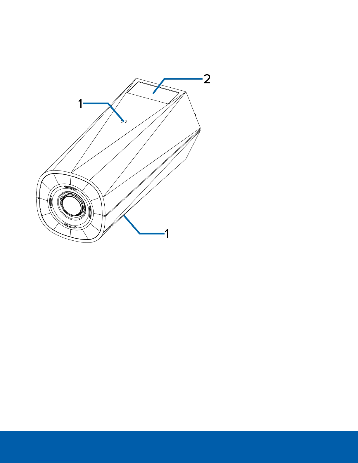
Overview
Front View
1.
Camera mounts
Provides mounting points for the camera. Mounts accept 1/4”-20 UNC bolts commonly found on tripods
and mounting brackets.
2.
Serial number tag
Device information, product serial number and part number label.
Overview 1
Page 7
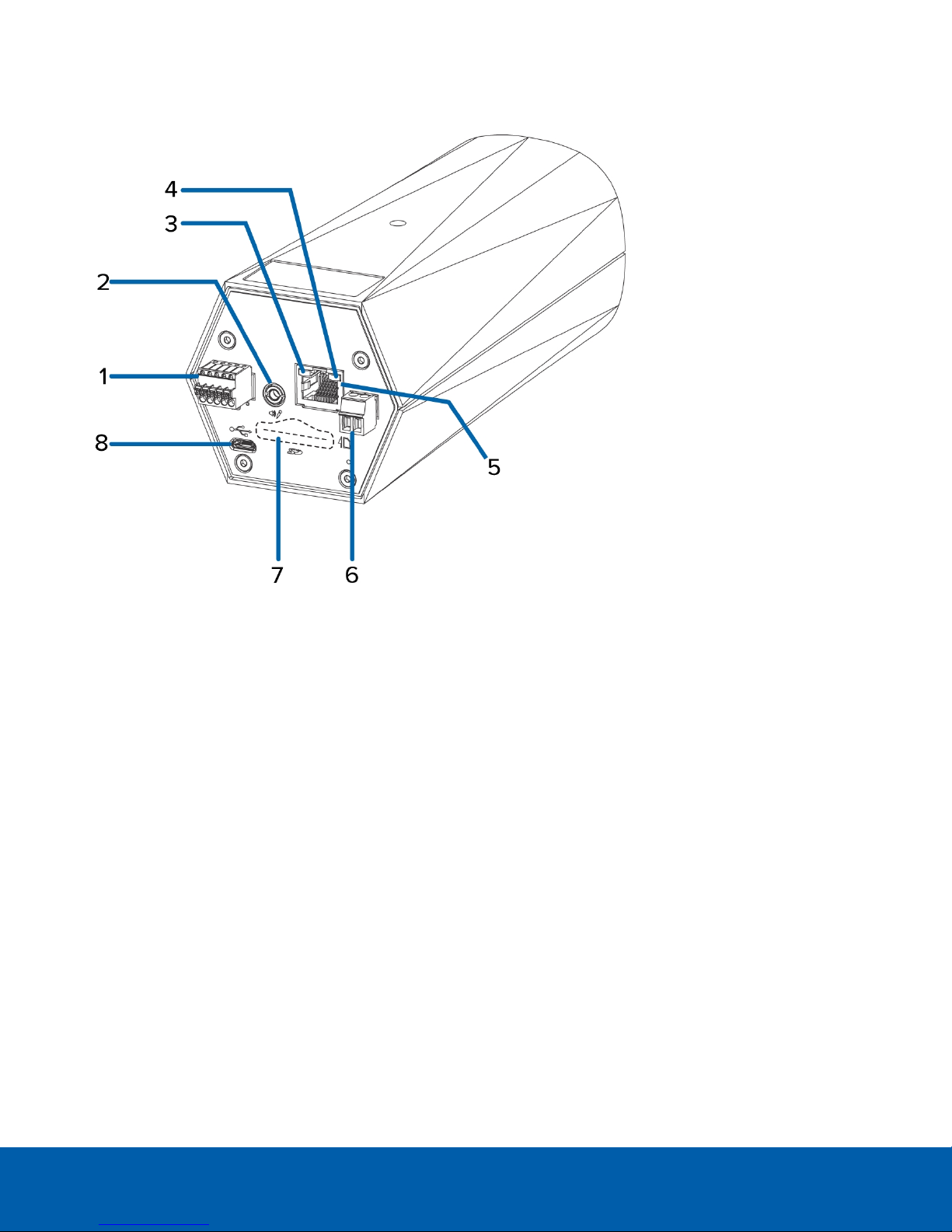
Rear View
1.
I/O connector block
Provides connections to external input/output devices.
2.
Audio/video connector
Accepts a mini-jack connector (3.5 mm).
3.
Connection status LED indicator
Provides information about device operation. For more information, see Connection Status LED Indicator
on page11.
4.
Link LED indicator
Indicates if there is an active connection in the Ethernet port.
5.
Ethernet port
Accepts an Ethernet connection to a network. Server communication and image data transmission occurs
over this connection. Also receives power when it is connected to a network that provides Power over
Ethernet.
6.
Power connector block
Accepts a terminal block with either an AC or DC power connection. DC input can be either polarity. Only
required when Power over Ethernet is not available.
7.
SD card slot
Rear View 2
Page 8

Accepts an SD card for onboard storage.
Not available on H4 Edge Solution (ES) Cameras.
8.
Micro USB port
Accepts a micro USB to USB adapter. Only required when using the Avigilon USB Wi-Fi Adapter.
Rear View 3
Page 9

Installation
Required Tools and Materials
l Small slotted screwdriver with 5/64” or 2 mm blade width — for connecting power when not using Power
over Ethernet.
l Mounting bracket, enclosure or tripod.
Camera Package Contents
l Avigilon H4 HD IP Camera
Installation Steps
Complete the following sections to install the device.
Mounting the Camera
Camera mounting points are provided on both the top and bottom of the camera body. Use these mounting
points to mount the camera on a bracket, in an enclosure, or on a tripod. The mounting points have ¼”-20 UNC
threaded holes which allow them to accept standard photographic mounting bolts.
Consult the installation instructions provided with the bracket, enclosure or tripod for detailed mounting
instructions.
WARNING — Use only UL-listed mounting bracket suitable for the mounting surface and minimum 0.7
kg (1.6 lb) weight.
Connecting Cables
Refer to the diagrams in the Overview section for the location of the different connectors.
To connect the cables required for proper operation, complete the following:
1. If external input or output devices are part of the installation (for example: door contacts, relays, etc.),
connect the devices to the I/O connector block.
2. If an external microphone needs to be connected to the camera, connect the device to the camera A/V
connector.
For more information see Connecting to Microphones, Speakers and Video Monitors on page9.
3. (1.0 and 2.0 megapixel models only) If an external video monitor needs to be connected to the camera,
connect the device to the camera A/V Connector.
For more information see Connecting to Microphones, Speakers and Video Monitors on page9.
4. Connect power using one of the following methods:
Installation 4
Page 10

o
Power over Ethernet (PoE) Class 3 — If PoE is available, the LEDs will turn on.
o
External Power — Connect an external 12 V DC or 24 V AC power source to the power connector
block.
5. Connect a network cable to the Ethernet port (RJ-45 connector).
The Link LED indicator will turn on once a network link has been established.
6. Check that the Connection Status LED indicator indicates the correct state. For more information, see
Connection Status LED Indicator on page11.
(Optional) Using the USB Wi-Fi Adapter
If you have a USB Wi-Fi Adapter (H4-AC-WIFI), attach it to the camera's micro USB port to access the camera's
mobile web interface.
After you connect to the Wi-Fi signal broadcast by the adapter, you can access the mobile web interface from
any mobile device using the following address:
http://camera.lan
For more information about configuring the camera from the mobile web interface see Avigilon USB Wi-Fi
Adapter System User Guide.
NOTE: The camera will reserve the 10.11.22.32/28 subnet for internal use while the USB Wi-Fi Adapter is plugged in.
Assigning an IP Address
The device automatically obtains an IP address when it is connected to a network.
NOTE: If the device cannot obtain an IP address from a DHCP server, it will use Zero Configuration Networking
(Zeroconf) to choose an IP address. When set using Zeroconf, the IP address is in the 169.254.0.0/16 subnet.
The IP address settings can be changed using one of the following methods:
l The mobile web interface using the USB Wifi Adapter. For more information, see (Optional) Using the USB
Wi-Fi Adapter above.
l Device's web browser interface: http://<camera IP address>/.
l Network Video Management software application (for example, the Avigilon Control Center™ software).
l ARP/Ping method. For more information, see Setting the IP Address Using the ARP/Ping Method on
page13.
NOTE: The default device username is administrator with no password.
Accessing the Live VideoStream
Live video stream can be viewed using one of the following methods:
l The mobile web interface using the USB Wifi Adapter. For more information, see (Optional) Using the USB
Wi-Fi Adapter above.
l Web browser interface: http://< camera IP address>/.
l Network Video Management software application (for example, the Avigilon Control Center software).
NOTE: The default camera username is administrator with no password.
(Optional) Usingthe USB Wi-Fi Adapter 5
Page 11

Aiming and Focusing the Camera
Use the camera web browser interface or the Avigilon Control Center software to aim and focus the camera.
Consult the software user guide for more information.
1. In the Image and Display settings area, use the Zoom controls to set the zoom position for the camera.
2. Focus the camera:
a. Click Auto Focus to focus the lens.
b. If the preferred focus was not achieved, use the focus near and far buttons to adjust the focus.
(Optional) Configuring SD Card Storage
To use the camera's SD card storage feature, you must insert an SD card into the card slot.
It is recommended that the SD card have a capacity of 8GB or more and a write speed of class 6 or better. If the
SD card does not meet the recommended capacity or write speed, the recording performance may suffer and
result in the loss of frames or footage.
1. Insert an SD card into the camera.
CAUTION — Do not force the SD card into the camera or you may damage the card and the
camera. The SD card can only be inserted in one direction.
2. Access the camera’s web interface to enable the onboard storage feature. For more information, see the
Avigilon High Definition H.264 Camera Web Interface User Guide.
Setting the Time
If you are installing an H4 ES camera, you must set the time on the camera. The ES camera model includes a
built-in server component that runs the ACC Server software directly on the camera. Since the camera is
accessed as its own network video recording server, you must set the time so that events and recorded video
occur at the correct time.
Follow the above procedure to manually configure the time settings:
1. Log in to the camera web interface.
2. Display the Setup > General page.
3. In the Time Settings area, select the camera time zone.
4. Click Apply.
5. At the bottom of the Time Settings area, click the Configure NTP Server link.
If you cannot see the link, select Network from the left menu pane.
6. In the NTP Server area, make sure the check box is selected then choose one of the following options:
l DHCP: select this option to automatically use an NTP server on the network.
l Manual: select this option to manually enter a specific NTPserver address in the NTP Server field.
7. Click Apply.
Configuring the Camera
Once installed, use one of the following methods to configure the camera:
Aiming and Focusing the Camera 6
Page 12

l If you have the USB Wifi Adapter, you can access the mobile web interface to configure the camera. For
more information, see Avigilon USB Wi-Fi Adapter System User Guide.
l If you have installed multiple cameras, you can use the Avigilon Camera Configuration Tool to configure
common settings. For more information, see the Avigilon Camera Configuration Tool User Guide.
l If the camera is connected to the Avigilon Control Center system, you can use the client software to
configure the camera. For more information, see the Avigilon Control Center Client User Guide.
l If the camera is connected to a third-party network management system, you can configure the camera's
specialty features in the camera's web browser interface. For more information, see the Avigilon Web
Interface User Guide - H4 HD.
l If you installed an H4 ES camera, you can use the Avigilon Control Center Client software to configure the
camera and the embedded software.
For More Information
Additional information about setting up and using the device is available in the following guides:
l Avigilon Control Center Client User Guide
l Avigilon High Definition H.264 Web Interface User Guide
l Avigilon USB Wi-Fi Adapter System User Guide
l Avigilon Camera Configuration Tool User Guide
These guides are available on the Avigilon website: avigilon.com/support-and-downloads.
For More Information 7
Page 13

Cable Connections
Connecting External Power
If PoE is not available, the camera needs to be powered through the removable power connector block. Refer
to the diagrams in this guide for the location of the power connector block.
The power consumption information is listed in the product specifications.
To connect power to the power connector block, complete the following steps:
1. Remove the power connector block from the camera.
2. Remove the insulation from ¼” (6mm) of the power wires. Do not nick or damage the wires.
3. Insert the two power wires into the two terminals on the power connector block. The connection can be
made with either polarity.
Use a small slotted (5/64” or 2mm blade width) screwdriver to loosen and tighten the terminals.
4. Attach the power connector block back into the camera.
WARNING — This product is intended to be supplied by a UL Listed Power Unit marked “Class 2” or
“LPS” or “Limited Power Source” with output rated 12 VDC or 24 VAC, 8 W min. or PoE rated 48 VDC, 8
W min.
Connecting to External Devices
External devices are connected to the camera through the I/O terminal block. The pinout for the I/O terminal
block is shown in the following diagram:
Cable Connections 8
Page 14

Figure 1: Example application.
1. Ground
2. Relay Input — To activate, connect the Input to the Ground pin. To deactivate, leave disconnected or
apply between 3-15 V.
3. Relay Output — When active, Output is internally connected with the Ground pin. Circuit is open when
inactive. Maximum load is 25 VDC, 120 mA.
4. RS-485 A — Non-inverting RS-485 pin for controlling external equipment.
5. RS-485 B — Inverting RS-485 pin for controlling external equipment.
l 0 — External Device
l * — Relay
l ** — Switch
Connecting to Microphones, Speakers and Video Monitors
The camera can be connected to an external microphone and speaker through the A/V connector. The camera
only supports line level mono audio input.
1.0 and 2.0 megapixel models can also be connected to an external monitor through the same A/V connector.
The video output signal is determined by the camera flicker control setting. When the camera flicker control is
set to 60 Hz, the video output signal is NTSC. When the flicker control is set to 50 Hz, the video output signal is
PAL. Use the camera web browser interface to configure the camera’s flicker control in the Image and Display
setup.
Connectingto Microphones, Speakers and Video Monitors 9
Page 15

All models of the camera use a mini-jack (3.5 mm) audio/video connector. The pinout for the connector is shown
in the following diagram:
Figure 2: Mini-jack A/V connector
1. Audio IN
2. Composite Video OUT
3. GND
4. Audio OUT
Connectingto Microphones, Speakers and Video Monitors 10
Page 16

Connection Status LED Indicator
Once connected to the network, the Connection Status LED indicator will display the progress in connecting to
the Network Video Management software.
The following table describes what the LED indicator shows:
Connection State
Obtaining IPAddress
Discoverable
Upgrading Firmware
Connected On
Connection Status
One short flash every
second
Two short flashes
every second
Two short flashes
and one long flash
every second
LED Indicator
Description
Attempting to obtain an IP address.
Obtained an IPaddress but is not connected to the
NetworkVideo Management software.
Updating the firmware.
Connected to the Network Video Management software or an
ACC™ Server. The default setting can be changed to "Off" using
the camera's web user interface. For more information see the
Web Interface User Guide - H4 HD.
Connection Status LEDIndicator 11
Page 17

Resetting to Factory Default Settings
If the device no longer functions as expected, you can choose to reset the device to its factory default settings.
Use the firmware revert button to reset the device. The firmware revert button is shown in the following diagram:
NOTE: For the ES camera models, resetting the camera will erase all recorded video from the camera.
For models that feature an SDcard slot, resetting the camera will not affect video that has been recorded to the
SD card.
Figure 3: Th e firmware reve rt button on the rear of th e camera
1. Ensure the device is powered on.
2. Using a straightened paperclip or similar tool, gently press and hold the firmware revert button.
3. Release the button after three seconds.
CAUTION — Do not apply excessive force. Inserting the tool too far will damage the camera.
Resetting to Factory Default Settings 12
Page 18

Setting the IP Address Using the ARP/Ping Method
Complete the following steps to configure the camera to use a specific IP address:
NOTE: The ARP/Ping Method will not work if the Disable setting static IP address through ARP/Ping method
check box is selected in the camera's web browser interface. For more information, see the Web User Interface
Guide - Avigilon High Definition H.264 IP Camera Models.
1. Locate and copy down the MAC Address (MAC) listed on the Serial Number Tag for reference.
2. Open a Command Prompt window and enter the following commands:
a. arp -s <New Camera IP Address> <Camera MAC Address>
For example: arp -s 192.168.1.10 00-18-85-12-45-78
b. ping -l 123 -t <New Camera IP Address>
For example: ping -l 123 -t 192.168.1.10
3. Reboot the camera.
4. Close the Command prompt window when you see the following message:
Reply from <New Camera IP Address>: ...
Setting the IP Address Using the ARP/PingMethod 13
Page 19

Specifications
Camera
Audio Input/Output Line level input and output, A/V mini-jack (3.5 mm)
Video Output (1 – 2 MP models) NTSC/PAL, A/V mini-jack (3.5 mm)
H4A-B1(-B)*:
l 4.7 – 84.6 mm, F1.6, P-iris
H4A-B2(-B)*:
Lens
l (1 – 3 MP models) 3-9 mm, F1.3, P-iris
l (5 – 8 MP models) 4.3-8 mm, F1.8, P-iris
H4A-B3(-B)*:
l (1 – 5 MP models) 9-22 mm, F1.6, P-iris
SD Storage
(Models with SD card
SD/SDHC/SDXC slot – minimum class 4; class 6 or better recommended
slots only)
Onboard Storage
(ES models only)
l (1 MP model) 128 G
l (2 – 3 MP models) 256 G
* These models are physically identical. (-B) * depicts an updated hardware version.
Network
Network 100Base-TX
Cabling Type CAT5
Connector RJ-45
ONVIF compliance version 1.02, 2.00, Profile S (www.onvif.org)
API
Compliant with version 2.2.0 of the Analytics Service Specification (bounding boxes and
scene descriptions not available with third party VMS)
Device Management
Protocols
Security
SNMP v2c
SNMP v3
Password protection, HTTPS encryption, digest authentication, WS authentication, user
access log, 802.1x port based authentication
IPv4, HTTP, HTTPS, SOAP, DNS, NTP, RTSP, RTCP, RTP, TCP, UDP, IGMP, ICMP, DHCP,
Streaming Protocols
Zeroconf, ARP, RTP/UDP, RTP/UDP multicast, RTP/RTSP/TCP, RTP/RTSP/HTTP/TCP,
RTP/RTSP/HTTPS/TCP, HTTP
Mechanical
Dimensions
L x W x H
H4A-B1(-B)* — 168 mm x 76 mm x 67 mm (6.6” x 3.0” x 2.6”)
H4A-B2(-B)*, H4A-B3(-B)* — 167 mm x 76 mm x 67 mm (6.6” x 3.0” x 2.6”)
H4A-B1(-B)* – 0.62 kg (1.4 lbs)
Weight
H4A-B2(-B)*, H4A-B3(-B)* – 0.57 kg (1.3 lbs)
Specifications 14
Page 20

Camera Mount ¼”-20 UNC (top and bottom)
* These models are physically identical. (-B) * depicts an updated hardware version.
Electrical
Power Consumption 8 W
VDC: 12 V +/- 10% 8 W min
Power Source
VAC: 24 V +/- 10% 12 VA min
PoE: IEEE802.3af Class 3 compliant
Power Connector 2-pin terminal block
RTC Backup Battery 3V manganese lithium
Environmental
Operating
Temperature
Storage
Temperature
-10 °C to 60 °C (14 °F to 140 °F)
8.0 MP model — -10 °C to 50 °C (14 °F to 122 °F)
-10 °C to +70 °C (14 °F to 158 °F)
Humidity 0-95% non-condensing
Certifications
UL
cUL
Certifications
CE
ROHS
WEEE
RCM
UL 60950-1
Safety
CSA 60950-1
IEC/EN 60950-1
Electromagnetic
Emissions
Electromagnetic
Immunity
FCC Part 15 Subpart B Class B
EN 55032 Class B
IC ICES-003 Class B
EN 61000-6-3
EN 61000-3-2
EN 61000-3-3
EN 55024
EN 61000-6-1
Specifications 15
Page 21

Limited Warranty and Technical Support
Avigilon warranty terms for this product are provided at avigilon.com/warranty.
Warranty service and technical support can be obtained by contacting Avigilon Technical Support:
avigilon.com/contact-us/.
Limited War ranty and Technical Support 16
 Loading...