

Page 1

User Guide
Avigilon High Definition H.264 IP Models:
H3-B1, H3-B2, H3-D1, H3-DC1, H3-DO1 H3-DP1, H3W-PTZ20 and ENC-4P-H264
UG-H3-A-Rev1
Page 2

Copyright © 9/20/12 Avigilon. All rights reserved.
No copying, distribution, publication, modification, or incorporation of this
document, in whole or part, is permitted without the express written permission of
Avigilon. In the event of any permitted copying, distribution, publication,
modification, or incorporation of this document, no changes in or deletion of
author attribution, trademark legend, or copyright notice shall be made. No part of
this document may be reproduced, stored in a retrieval system, published, used
for commercial exploitation, or transmitted, in any form by any means, electronic,
mechanical, photocopying, recording, or otherwise, without the express written
permission of Avigilon.
Windows and Internet Explorer are trademarks of Microsoft Inc.
Mac, Apple, and Safari are trademarks of Apple Inc.
iOS is a trademark of Cisco licensed to Apple.
Opera is a trademark of Opera Software ASA.
Android and Chrome are trademarks of Google Inc.
Avigilon has made every effort to identify trademarked properties and owners on
this page. All brands and product names used in this document are for
identification purposes only and may be trademarks or registered trademarks of
their respective companies.
Avigilon
Tel +1.604.629.5182
Fax +1.604.629.5183
http://www.avigilon.com
Revised 9/20/12
Page 3

Table of Contents
Introduction . . . . . . . . . . . . . . . . . . . . . . . . . . . . . . . . . 1
System Requirements . . . . . . . . . . . . . . . . . . . . . . . . . . . . 1
Accessing the Camera Web Interface . . . . . . . . . . . .2
Live View . . . . . . . . . . . . . . . . . . . . . . . . . . . . . . . . . . . 3
Using the Camera Zoom and Focus Controls . . . . . . . . . 3
Using Camera Presets . . . . . . . . . . . . . . . . . . . . . . . . . . . 4
Using the PTZ Camera Controls . . . . . . . . . . . . . . . . . . . . 5
Using the Encoder PTZ Controls . . . . . . . . . . . . . . . . . . . . 6
Setup . . . . . . . . . . . . . . . . . . . . . . . . . . . . . . . . . . . . . . 7
General . . . . . . . . . . . . . . . . . . . . . . . . . . . . . . . . . . . . . . . 7
Network . . . . . . . . . . . . . . . . . . . . . . . . . . . . . . . . . . . . . . . 8
Image and Display . . . . . . . . . . . . . . . . . . . . . . . . . . . . . . . 9
Compression and Image Rate . . . . . . . . . . . . . . . . . . . . . 11
Configuring RTSP Stream URI . . . . . . . . . . . . . 12
Motion Detection . . . . . . . . . . . . . . . . . . . . . . . . . . . . . . . 13
Privacy Zones . . . . . . . . . . . . . . . . . . . . . . . . . . . . . . . . . 15
Digital Inputs and Outputs . . . . . . . . . . . . . . . . . . . . . . . . 16
Microphone . . . . . . . . . . . . . . . . . . . . . . . . . . . . . . . . . . . 16
Speaker . . . . . . . . . . . . . . . . . . . . . . . . . . . . . . . . . . . . . . 17
Users . . . . . . . . . . . . . . . . . . . . . . . . . . . . . . . . . . . . . . . . 17
Adding a User . . . . . . . . . . . . . . . . . . . . . . . . . . 17
Editing Users and Passwords . . . . . . . . . . . . . . 18
System . . . . . . . . . . . . . . . . . . . . . . . . . . . . . . . . . . . . . . 19
Upgrading the Camera Firmware . . . . . . . . . . . 19
Device Log . . . . . . . . . . . . . . . . . . . . . . . . . . . . . . . . . . . 20
English
PTZ Camera . . . . . . . . . . . . . . . . . . . . . . . . . . . . . . . . 21
PTZ Tours . . . . . . . . . . . . . . . . . . . . . . . . . . . . . . . . . . . . 21
Editing PTZ Tours . . . . . . . . . . . . . . . . . . . . . . . 22
PTZ Limits . . . . . . . . . . . . . . . . . . . . . . . . . . . . . . . . . . . . 23
Encoder . . . . . . . . . . . . . . . . . . . . . . . . . . . . . . . . . . . 25
Selecting a Port or Channel Option . . . . . . . . . . . . . . . . . 25
Enabling Video Input Termination . . . . . . . . . . . . . . . . . . 25
Setting Up PTZ . . . . . . . . . . . . . . . . . . . . . . . . . . . . . . . . 25
Page 4

English
Page 5

Introduction
All Avigilon High Definition H.264 IP cameras, dome cameras and
encoders contain a web interface that allows you to view live video and
configure the device through a web browser.
Before you access the web interface, make sure you complete all the
procedures described in the device installation guide.
System Requirements
The web interface can be accessed from any Windows®, Mac® or mobile
device using one of the following browsers:
• Windows® Internet Explorer® browser version 7.0 or later
®
• Mozilla
• Opera
• Chrome™ browser 8.0 or later
• Safari
• Android™ 2.2 (Froyo) browser or later
Firefox® browser version 3.6 or later
©
browser 9.0 or later
®
5.0 or later
English
• Apple
®
iOS 5.0 browser or later.
1
Page 6

English
Accessing the Camera Web Interface
After the camera or encoder has been installed, you need the device’s IP
address to access the web interface. The IP address can be found in one
of the following places:
• Avigilon Camera Installation Tool: click the Connect to
Camera button to see the details of the connected camera
or encoder.
•
Avigilon Control Center Client: open the Setup dialog box to
see the details of the selected device.
Once you have the IP address, complete the following procedure to
access the web interface:
1. On a computer with internet access, enter the device’s IP address
into a web browser:
http://<camera IP address>/
For example, http://192.168.1.40/
2. You will automatically be prompted to enter your username and
password to access the device.
The default username is admin, and the default password is
admin. It is recommended that you change the default password
after your first login. For more information, see Editing Users and
Passwords on page 18.
NOTE: You can only change the device password in the web interface.
The password cannot be changed in the network video
management software.
2
Page 7
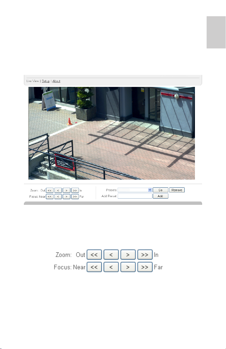
Live View
After you login, the first page you see is the Live View. The Live View
contains an image panel that displays the live video stream.
The menu links at the top left corner takes you to each of the pages in the
web interface. Click Live View any time to return to this page.
English
The following sections describe the buttons that may be displayed under
the image panel if users have access to PTZ controls. To give a user PTZ
controls, see Adding a User on page 17.
Using the Camera Zoom and Focus Controls
• To zoom out, click << to take a large step or < to take a
small step.
• To zoom in, click >> to take a large step or > to take a small
step.
3
Page 8
English
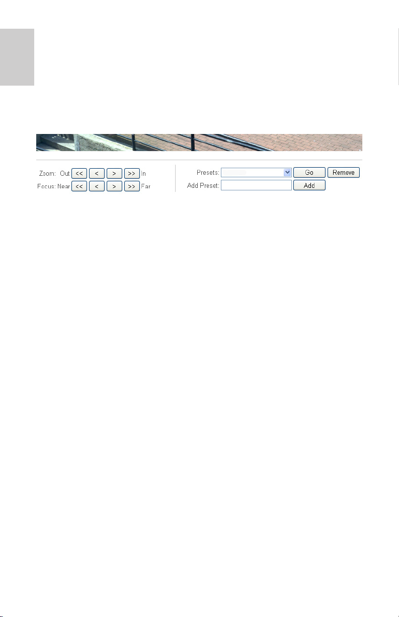
• To focus towards zero, click << to take a large step or < to
take a small step.
• To focus towards infinity, click
>> to take a large step or > to
take a small step.
Using Camera Presets
1. On the Live View page, use the Zoom and Focus controls to focus
the camera on a specific point in the video image.
2. To add this camera position as a preset, enter a name in the Add
Preset field then click Add.
3. To use a preset, select a configured preset from the Presets drop
down list and click Go.
4. To delete a preset, select a preset from the drop down list then
click Remove.
The presets can also be configured in the Avigilon Control Center Client
software through the PTZ controls.
4
Page 9
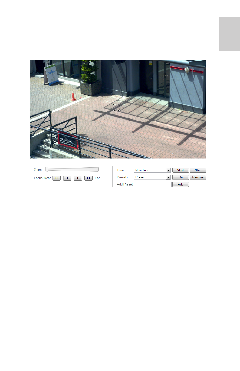
Using the PTZ Camera Controls
If you are accessing a standalone pan-tilt-zoom (PTZ) camera, you can
control Focus and Presets in the same way as other cameras but you also
have access to other features that are specific to the PTZ camera.
1. To zoom the camera:
• Adjust the Zoom slider.
• Or, click and drag to create a green box on the image panel
to define the area you want to zoom in and see.
2. To move the camera:
• Click anywhere on the image panel to center the camera to
that point.
• Or, drag your mouse from center to move the camera in that
direction. The farther the arrow is from center, the faster the
camera will move.
3. To perform a guard tour, select a tour from the drop down list then
click Start. To setup a tour, see PTZ Tours on page 21.
4. To stop a guard tour, click Stop. You can pause a tour at any time
just by using the other PTZ controls.
English
5
Page 10
English
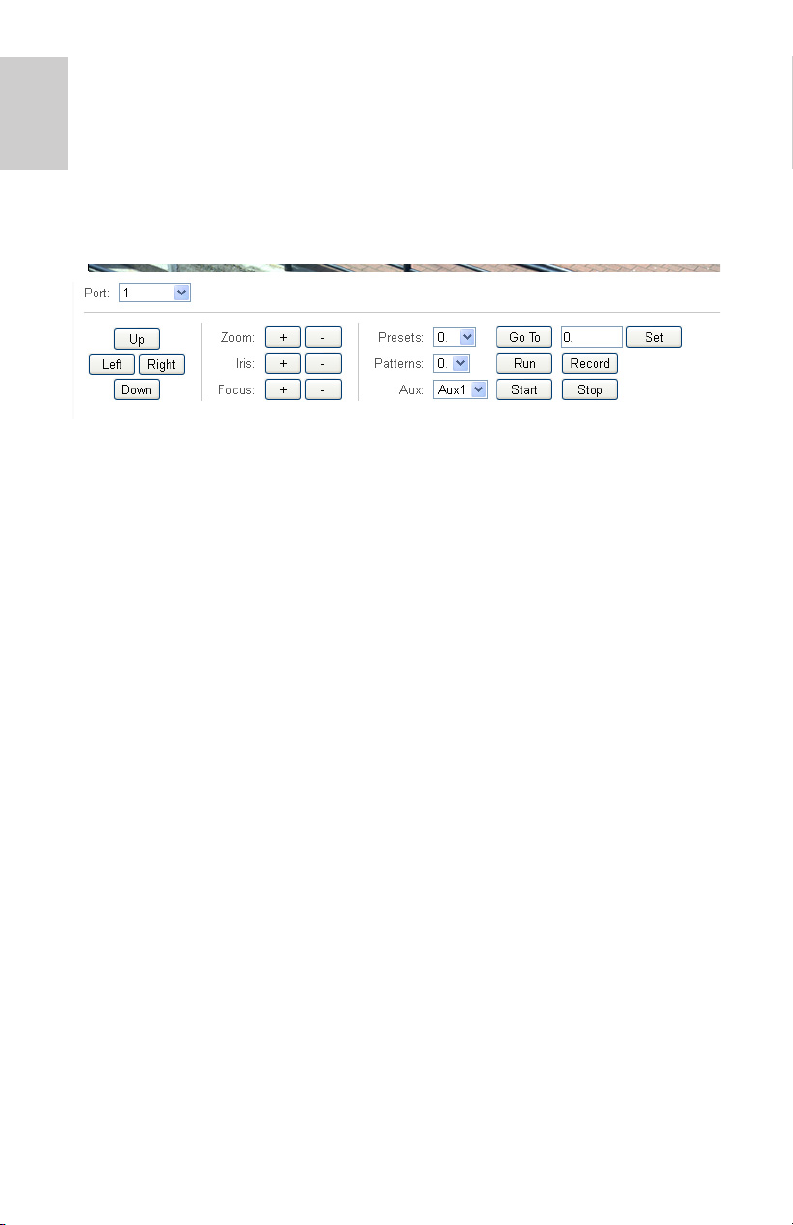
Using the Encoder PTZ Controls
Any camera that is connected to an H.264 encoder can have the PTZ
option enabled. Once enabled, the full pan, tilt and zoom controls are
displayed in the Live View for that camera.
To enable PTZ for cameras that are connected to an encoder, see Setting
Up PTZ on page 25.
1. Select a camera from the Port drop down list.
NOTE: The PTZ controls are only displayed when the camera is displayed
by itself.
2. To move the camera field of view, click one of the directional
buttons on the far left.
3. To control the camera’s Zoom, Iris or Focus, click the + or -
buttons.
4. For Presets, you can perform any of the following:
• To add a preset, move the camera’s field of view into position
then give the preset a name and click Set.
• To use a preset, select a name or number from the drop
down list and click Go To.
5. For Patterns, you can perform any of the following:
• To record a pattern, select a number from the drop down list
then click Record. Use the directional buttons to move the
camera and create the pattern. When you are done, click
Stop.
• To run a pattern, select a number from the drop down list
and click Run.
6. To activate an auxiliary command, select an Aux# from the drop
down list and click Start. When you are finished, click Stop.
6
Page 11
Setup
NOTE: Some or all Setup pages may not be displayed if you do not have
the required user permissions.
The device’s factory default settings allow you to use the camera or
encoder immediately after installation. If you have special requirements,
you can customize the settings through the web interface.
A Restore Default button is available on each Setup page to allow you to
restore the factory default settings.
Be aware that some of the settings are only available through the camera
web interface and can not be changed in the network video management
software.
The following Setup pages in the web interface are common across all
Avigilon H.264 devices unless otherwise noted.
For the settings that are specific to PTZ cameras, see PTZ Camera on
page 21.
For the settings that are specific to encoders, see Encoder on page 25.
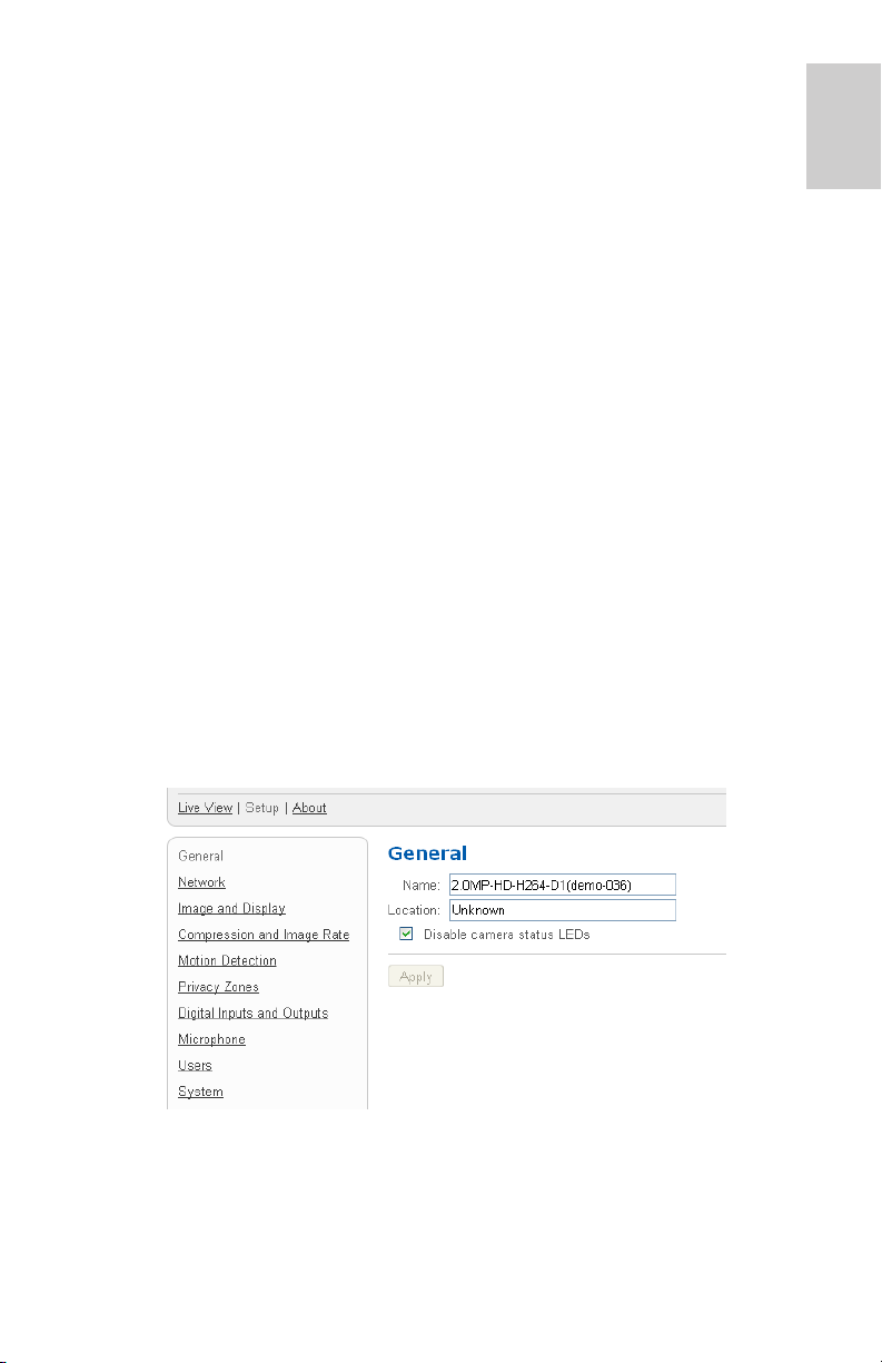
General
When you select the Setup link, the first page you see is the General
page. The General page allows you to set the device identity.
English
1. In the Name field, give the device a meaningful name.
2. In the Location field, describe the device’s location.
3. Select the Disable camera status LEDs check box to disable the
LEDs located on the device.
4. Click Apply.
7
Page 12

English
Network
On the Network page, you can change how the device connects to the
server network and choose how the device keeps time.
NOTE: You can only set the HTTPS port, the RTSP port, and the NTP
Server in the camera web interface.
1. In the Address and Hostname area, select how the device obtains
an IP address:
• Obtain an IP address automatically: select this option to
connect to the network through an automatically assigned IP
address.
The IP address is obtained from a DHCP server. If it
can not, the IP address will default to addresses in the
169.254.x.x range.
• Use the following IP address: select this option to
manually assign a static IP address.
Enter the IP Address, Subnet Mask, and the Default
Gateway you want to use.
2. If you need to customize the hostname, enter it in the Hostname
field.
3. In the Control Ports area, you can specify which control ports are
used to access the device. You can enter any port number
between 1 and 65534. The default port numbers are:
• HTTP Port: 80
• HTTPS Port: 443
• RTSP Port: 554
4. In the NTP Server area, select how the device keeps time.
Avigilon cameras and encoders do not have an internal clock so it
uses a Network Time Protocol (NTP) server to keep time.
• Obtain NTP server via DHCP: select this option to
automatically use the same NTP server as the rest of the
network.
• Use the following NTP server: select this option to
manually set which NTP server is used.
5. Click Apply when you are done.
8
Page 13
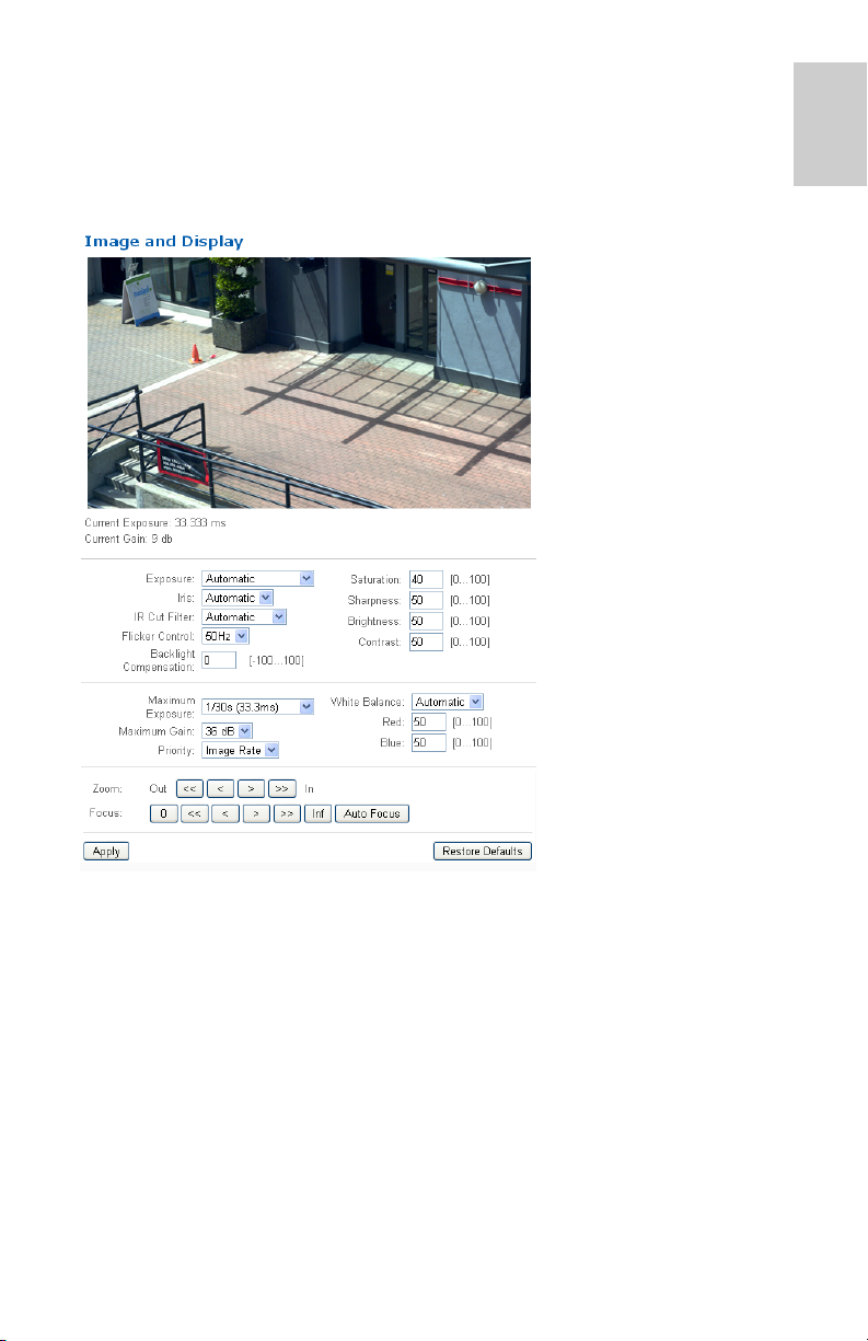
Image and Display
NOTE: This setup page is not available for encoders, and some options
are not available if they are not supported by the camera
On the Image and Display
page, you can control the
camera’s video display
settings.
The Image and Display
page includes an image
panel that displays the
camera’s live video
stream. When you click
Apply to save your
changes, the video
stream is updated.
Avigilon cameras have
electronic zoom and
focus controls, so you can
set the camera’s zoom
and focus through this
page as well.
English
1. Use the Zoom controls to adjust the camera’s zoom position.
2. If the camera has a built-in auto focus feature, you can select the
Continuous Focus option to enable the camera to focus itself
whenever the scene changes.
3. To manually focus the camera, select Open in the Iris drop down
list then use the Focus buttons to focus the camera.
The left arrow buttons focus the camera towards Zero (0), and the
right arrow buttons focus the camera towards Infinity. Click the
Auto Focus button to enable the camera to automatically focus
once.
NOTE: Once the focus is manually set, it will not change.
9
Page 14
English
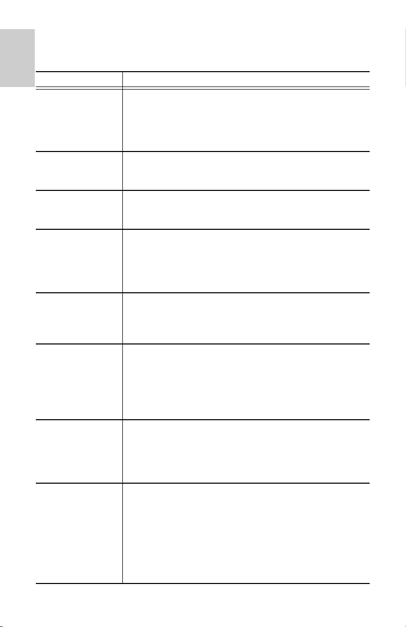
4. To adjust the video image, make changes to any of the following
settings as required..
Option Description
Exposure You can allow the camera to control the exposure by
selecting Automatic, or you can set a specific
exposure rate.
NOTE: Increasing the manual exposure time may
affect the image rate.
Iris You can allow the camera to control the iris by
selecting Automatic, or you can manually set it to
Open or Closed.
IR Cut Filter You can allow the camera to control the infrared cut
filter by selecting Automatic, or set the camera to
Color or Monochrome mode.
Flicker Control If your video image flickers because of the fluorescent
lights around the camera, you can reduce the effects
of the flicker by setting the Flicker Control to the same
frequency as your lights. Generally, Europe is 50Hz
and North America is 60Hz.
Backlight
Compensation
Maximum
Exposure
Maximum Gain You can limit the automatic gain setting by selecting a
Priority You can set Image Rate or Exposure as the priority.
If your scene has areas of intense light that cause the
overall image to be too dark, change the Backlight
Compensation value until you achieve a well exposed
image
You can limit the automatic exposure setting by
selecting a maximum exposure level.
By setting a maximum exposure level for low light
situations, you can control the camera's exposure
time to let in the maximum amount of light without
creating blurry images.
maximum gain level.
By setting the maximum gain level for low light
situations, you can maximize the detail of an image
without creating excessive noise in the images.
When set to Image Rate, the camera will maintain the
set image rate as the priority and will not adjust the
exposure beyond what can be recorded for the set
image rate.
When set to Exposure the camera will maintain the
exposure setting as the priority, and will override the
set image rate to achieve the best image possible.
10
Page 15
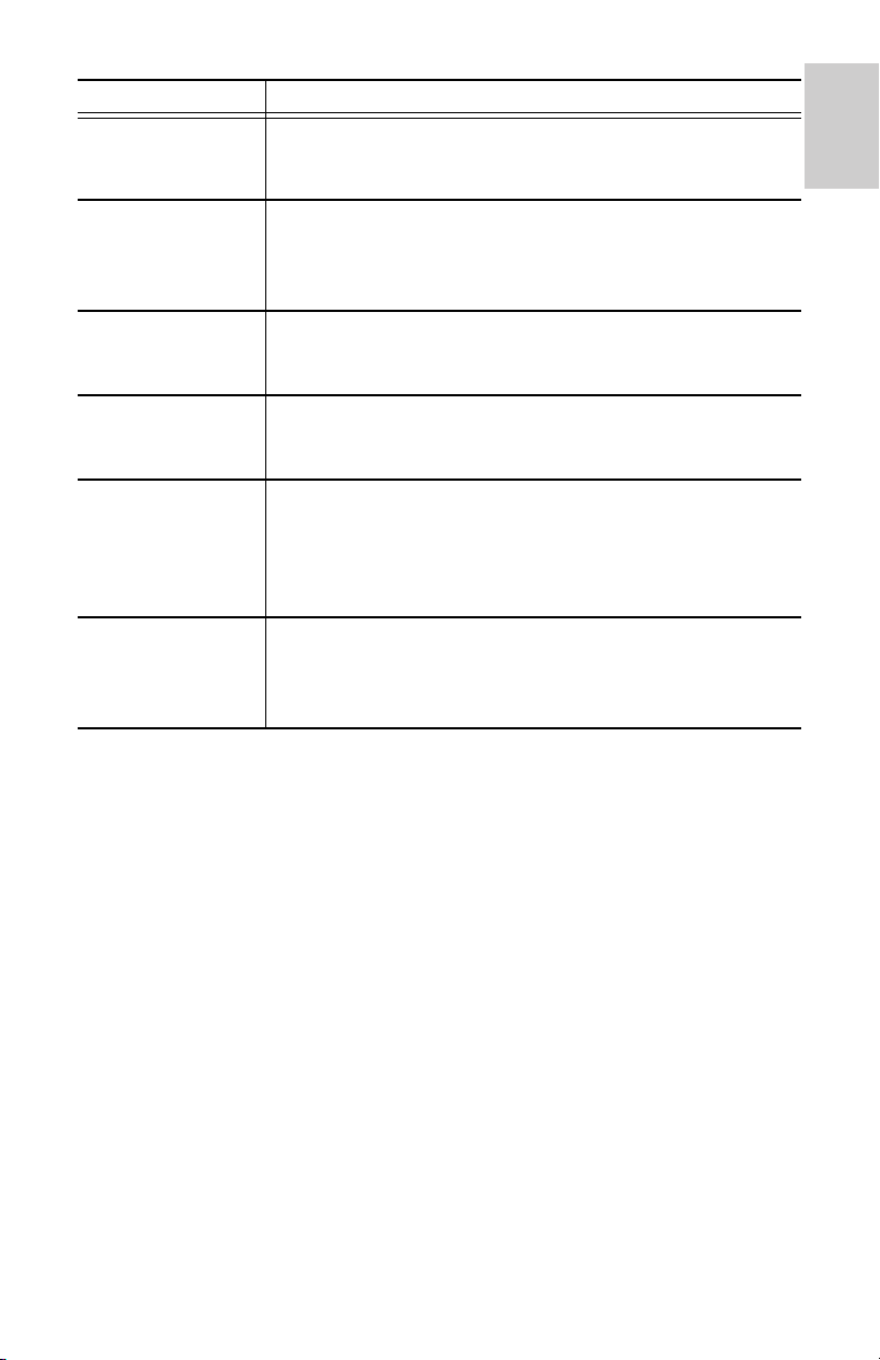
Option Description
Saturation You can adjust the video’s color saturation by entering
a percentage number. 0 creates a black and white
image, while 100 creates intense color images.
Sharpness You can adjust the video’s sharpness by entering a
percentage number. 0 applies the least amount of
sharpening, while 100 applies the most sharpening to
make the edges of objects more visible.
Brightness You can adjust the video’s brightness by entering a
percentage number. 0 creates a dark image, while
100 creates a light-filled image.
Contrast You can adjust the video’s contrast by entering a
percentage number. 0 applies the least amount of
contrast, while 100 applies the most contrast.
White Balance You can control the white balance settings to adjust for
differences in light.
You can allow the camera to control the white balance
by selecting Automatic, or select Custom and
manually set the Red and Blue settings.
WDR
(PTZ only)
You can enable automatic color adjustments through
Wide Dynamic Range (WDR). This allows the camera
to adjust the video image to accomodate scenes
where bright light and dark shadow are clearly visible.
English
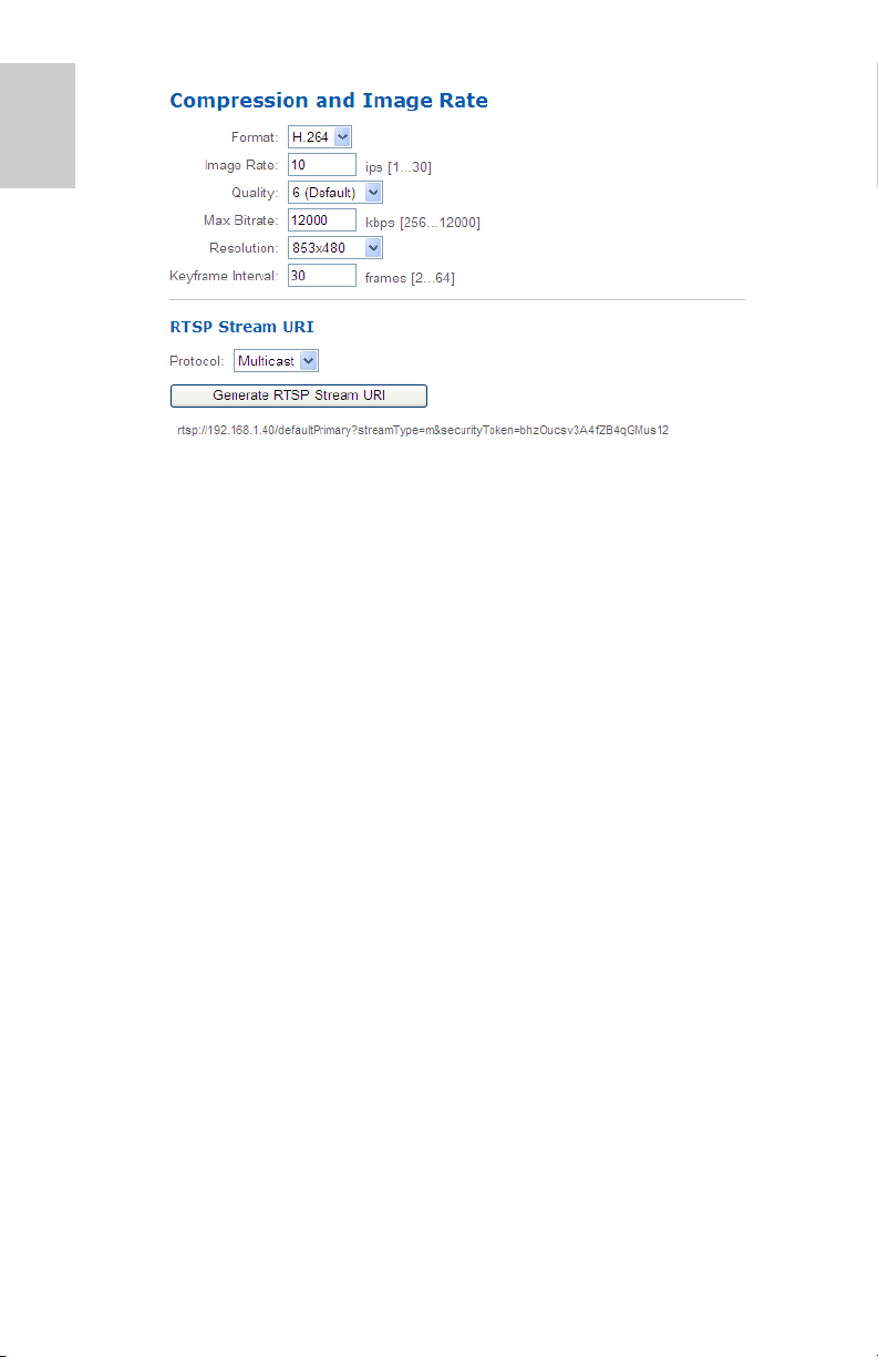
Compression and Image Rate
On the Compression and Image Rate page, you can change the camera’s
compression and image quality settings for sending video over the
network.
To enable easy access and lower bandwidth usage, the web interface
only displays video in JPEG format and cannot be changed. The settings
on this page only affect the video transmitted to the network video
management software.
Avigilon cameras have dual stream capabilities, so even when the
camera’s streaming format is set to H.264, the camera's web interface
can still display live video in JPEG format.
However, cameras that are connected to an Avigilon encoder do not
typically have multi-stream capabilities. So once you set the video
streaming format to H.264, live video from that camera is no longer
displayed in the web interface.
NOTE: You can only set the RTSP stream settings in the camera web
interface.
11
Page 16
English
1. In the Format drop down list, select the preferred streaming
format for displaying the camera video in the network video
management software.
2. In the Image Rate field, enter a number between 1-30 to indicate
how many images per second you want the camera to stream
over the network.
3. In the Quality drop down list, select the desired image quality
level.
Image quality setting of 1 will produce the highest quality video
and require the most bandwidth.
4. In the Max Bitrate field, enter the maximum bandwidth the
camera can use. You can enter any number between 25612000 kbps.
5. In the Resolution drop down list, select the preferred image
resolution.
6. In the Keyframe Interval field, enter the number of frames
between each keyframe. You can enter any number between 2-
64.
7. Click Apply to save your changes.
Configuring RTSP Stream URI
In the Compression and Image Rate page, you can also configure the
camera’s real time streaming protocol (RTSP). The RTSP Stream URI
allows you to watch the camera’s live video stream from any application
that supports viewing RTSP streams, including many video players.
12
Page 17
1. To set the protocol, select either Unicast or Multicast in the
RTSP Stream URI area then click Apply.
2. To watch the camera’s live video stream from an external video
player, click Generate RTSP Stream URI.
a. Copy and paste the generated address in to your video
player. DO NOT open the live video stream yet.
b. Add your username and password to the beginning of the
address in this format:
rtsp://<username>:<password>@<generated RTSP Stream
URI>/
For example: rtsp://admin:admin@192.168.1.79/
defaultPrimary?streamType=u
c. Open the live video stream.
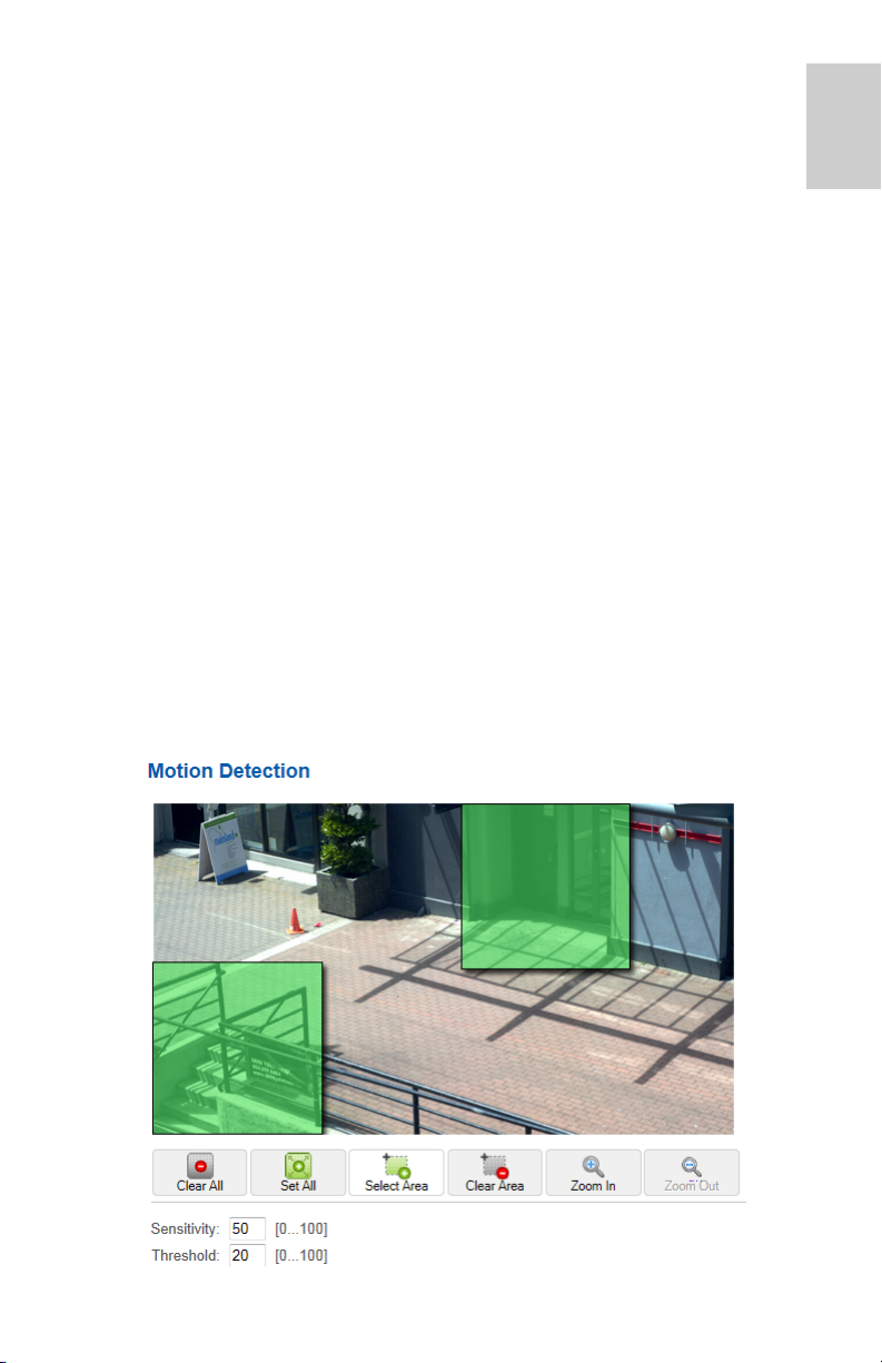
Motion Detection
On the Motion Detection page, you can define the green motion detection
areas in the camera’s field of view. Motion detection is ignored in areas
not highlighted in green.
To help you define motion sensitivity and threshold, motion is highlighted
in red in the image panel.
English
13
Page 18

English
1. The entire field of view is highlighted for motion detection by
default. To define the motion detection area, use any of the
following tools:
• Click Clear All to remove all motion detection areas on the
video image.
• Click Set All to set the motion detection area to span the
entire video image.
• To set a specific motion detection area, click Select Area
then click and drag anywhere on the video image.
• To clear a specific motion detection area, click Clear Area
then click and drag over any motion detection area.
• Use the Zoom In and Zoom Out buttons to locate specific
areas in the video image.
2. In the Sensitivity field, enter a percentage number to define how
much each pixel must change before it is considered in motion.
The higher the sensitivity, the smaller the amount of pixel change
is required before motion is detected.
3. In the Threshold field, enter a percentage number to define how
many pixels must change before the image is considered to have
motion.
The higher the threshold, the higher the number of pixels must
change before the image is considered to have motion.
4. Click Apply to save your changes.
14
Page 19
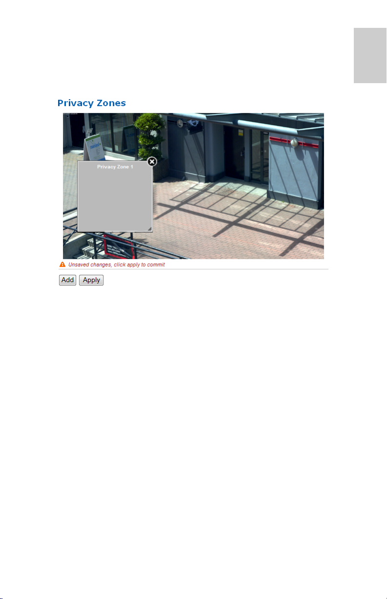
Privacy Zones
On the Privacy Zones page, you can set privacy zones in the camera’s
field of view to block out areas that you do not want to see or record. The
camera supports up to four privacy zones.
1. To add a privacy zone, click Add. A gray privacy zone box is
added to the video image.
2. To define the privacy zone area, perform any of the following:
a. Drag the bottom or right side of the gray box to resize the
privacy zone.
English
NOTE: Privacy zones can only be rectangular in shape.
b. Click the center of the gray box then drag to move the
privacy zone.
c. Click the X at the top right corner of the gray box to delete
the privacy zone.
3. Click Apply to save the privacy zone settings.
4. If you are using a PTZ camera, a list of privacy zones is available
at the bottom of the page. When you click one of the privacy
zones, the camera moves and highlights that privacy zone in the
image panel.
15
Page 20
English
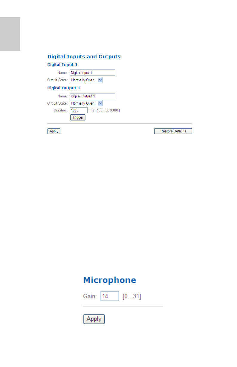
Digital Inputs and Outputs
On the Digital Inputs and Outputs page, you can set up the external input
and output devices that are connected to the camera.
1. In the Digital Inputs area, name the digital input and select the
digital input’s circuit state.
2. In the Digital Outputs area, name the digital output and select the
digital output’s circuit state.
3. In the Digital Outputs Duration field, enter how long the digital
output is active for when triggered. You can enter any number
between 100-3,600,000 milliseconds.
4. Click Trigger to manually trigger the digital output from the web
interface.
5. Click Apply to save your changes.
Microphone
If a microphone is connected to the camera, you can adjust the gain on
the Microphone page. The higher the gain setting, the higher the
microphone volume.
16
Page 21
• Enter a number between the available range displayed on
the right then click
Apply.
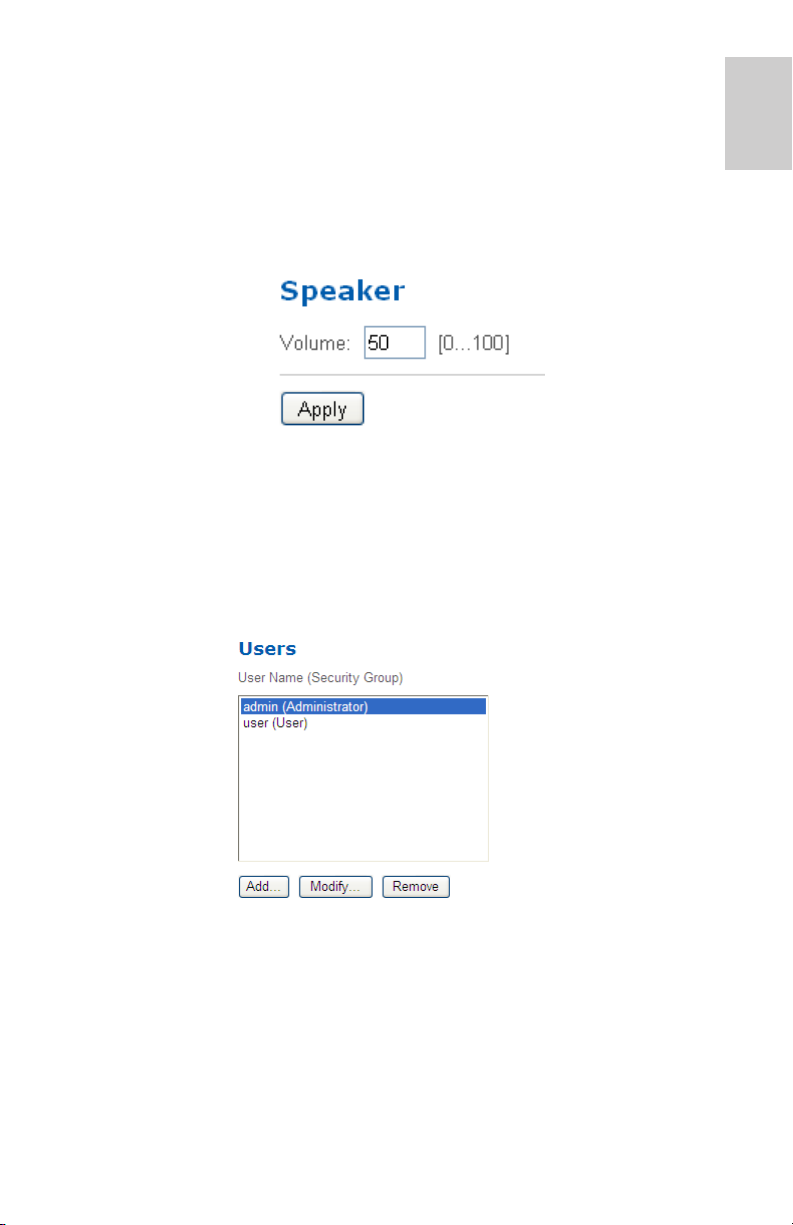
Speaker
If a speaker is connected to the camera, you can adjust the volume on the
Speakers page.
• Enter a number between 0-100 to set the speaker volume
then click
Apply.
Users
On the Users page, you can add new users, edit existing users, and
change passwords.
English
Adding a User
1. On the Users page, click Add....
2. On the Add User page, enter a username and password for the
new user.
3. In the Security Group drop down list, select the access
permissions available to this new user.
17
Page 22

English
• Administrator: full access to all the available features in the
camera web interface, including PTZ controls.
• Operator: has access to the Live View and PTZ controls but
limited access to the Setup features. The new user can only
access the Image and Display page, Compression and
Image Rate page, Motion Detection page, Privacy Zones
page, Digital Inputs and Outputs page, Microphone page
and the Speaker page.
• User: has access to the Live View and optional PTZ
controls, but cannot access any of the Setup pages. To
enable the PTZ controls, select the Use PTZ Controls
check box.
4. Click Apply to add the user.
Editing Users and Passwords
1. On the Users page, select a user from the User Name list and
click Modify.
2. To change the user’s password, enter a new password for the
user.
3. To change the user’s security group, select a different group from
the Security Group drop down list.
NOTE: You cannot change the security group for the admin account.
4. Click Apply to save your changes.
18
Page 23
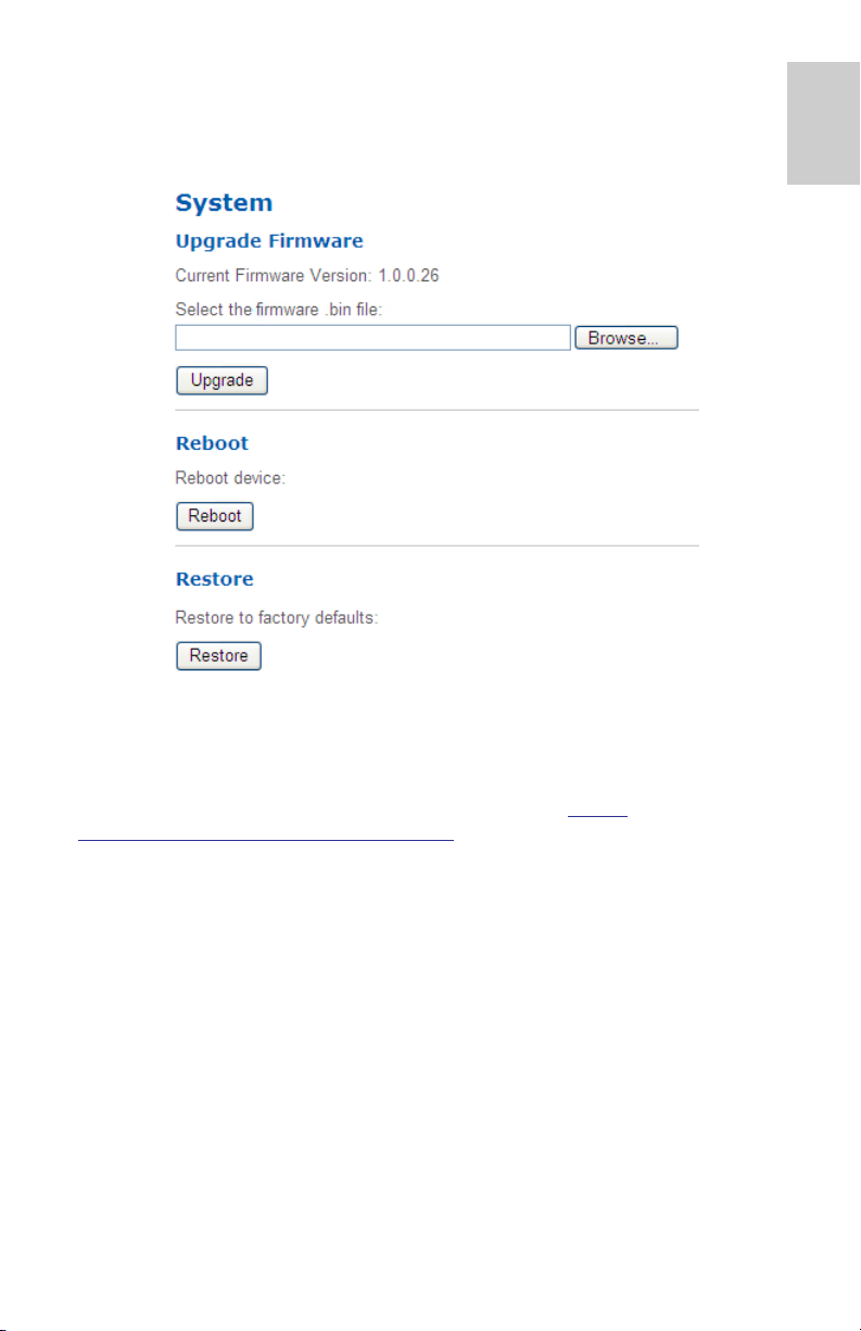
System
On the System page, you can manually upgrade the camera firmware,
reboot the camera, and restore all of the camera’s factory default settings.
Upgrading the Camera Firmware
English
To manually upgrade the camera’s firmware, download the latest version
of the firmware .bin file from the Avigilon website (http://
www.avigilon.com/support/firmware) and complete the following
procedure:
1. Click Browse and locate the downloaded firmware file.
2. Click Upgrade. Wait until the camera upgrade is complete.
19
Page 24
English
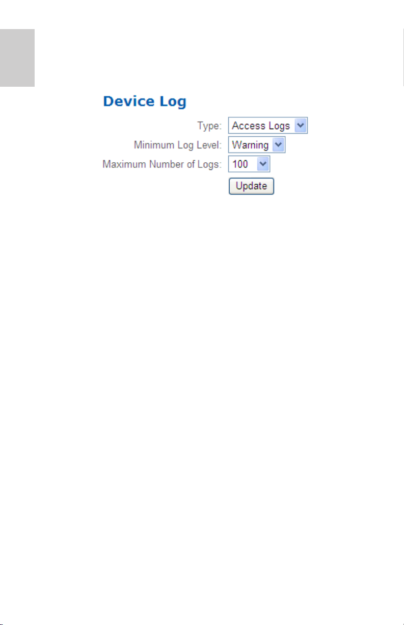
Device Log
The Device Log page allows you to view the camera’s system logs and
the camera access logs.
1. In the Type drop down list, select either Access Logs or System
Logs.
2. In the Minimum Log Level drop down list, select the log
messages you want to see.
3. In the Maximum Number of Logs drop down list, select the
number of log messages you want displayed each time.
4. Click Update. The logs are displayed below.
20
Page 25
PTZ Camera
Avigilon H.264 PTZ cameras use many of the same settings as the other
cameras. The following settings are only available to PTZ cameras.
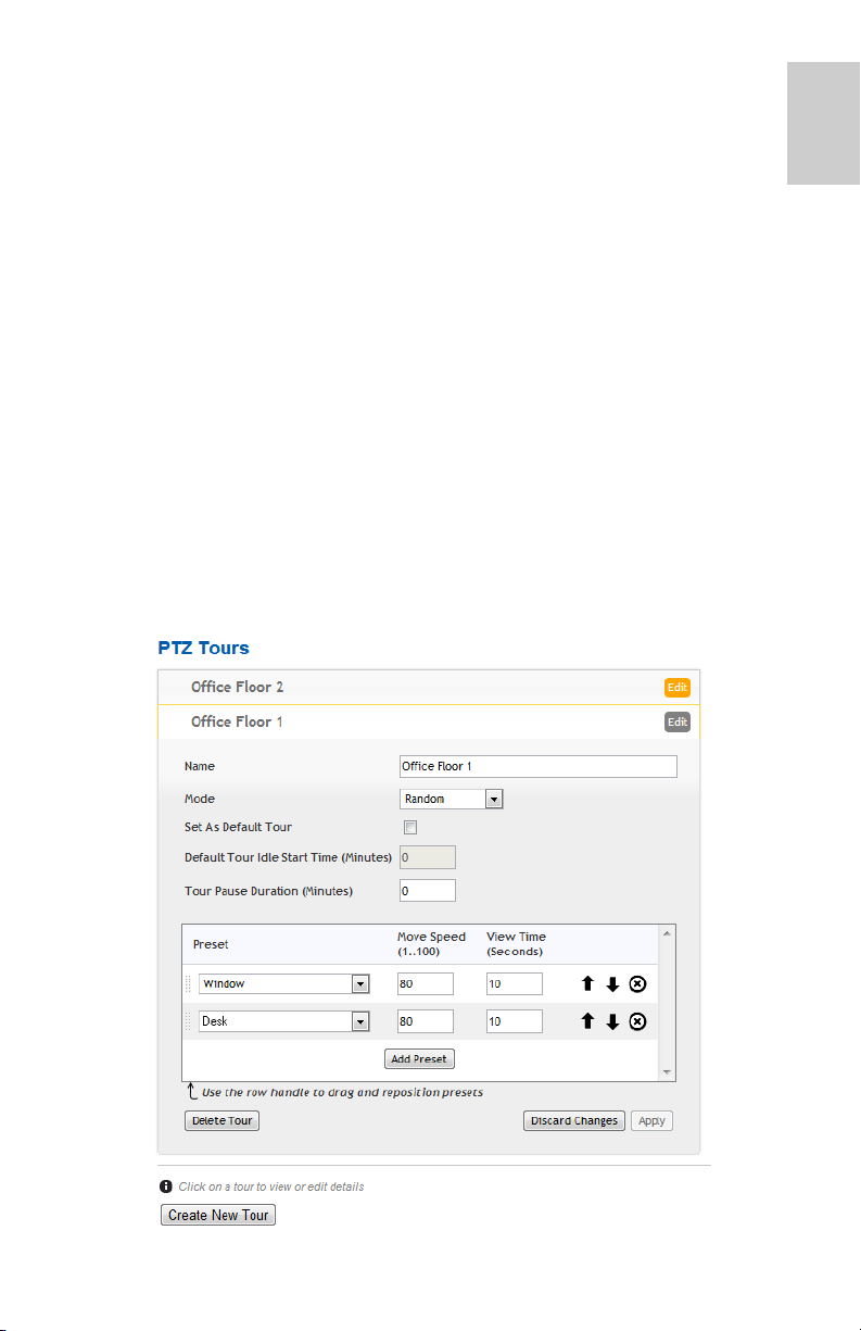
PTZ Tours
For PTZ cameras, you have the option of running a Tour on the Live View
page. Tours allow the PTZ camera to automatically move between a
series of preset positions, and can be set to pause at each preset for a
specific amount of time for video monitoring.
To create a tour, complete the following:
NOTE: All the required presets must be added before a new tour can be
created. See Using Camera Presets on page 4 for more
information.
1. Among the Setup options, click PTZ Tours.
2. Click Create New Tour.
English
21
Page 26

English
3. Give the tour a name.
4. In the Mode drop down list, select one of the following:
• Sequential: the PTZ camera will go to each preset in the set
order.
• Random: the PTZ camera will go to each preset in random
order.
5. Select the Set as default tour check box if you want this tour to
run automatically.
• The Default Tour Idle Start Time field is now enabled, enter
the amount of time the PTZ camera must be idle for before
this tour automatically begins.
6. To add a preset, click Add Preset and a preset is added to the
list.
a. In the Preset column, select a preset from the drop down list.
b. In the Move Speed column, enter how fast you want the PTZ
camera to move to this preset. The speed is 80% by default.
c. In the View Time column, enter the amount of time you want
the PTZ camera to stay at this preset position. The view time
is 10 seconds by default.
d. Continue until all the presets for this tour have been added.
7. To remove a preset, click the (x) icon to the far right of the preset.
8. To re-order a preset, click the up and down arrows or click and
drag the left edge of the preset through the list.
9. Click Apply to save the tour.
Editing PTZ Tours
1. Among the Setup options, click PTZ Tours.
2. Click Edit.
3. Make the changes you need.
4. To undo the changes that you’ve made, click Discard Changes.
5. Click Apply to save your changes.
6. To delete the tour, click Delete Tour. When the confirmation
dialog box appears, click OK.
22
Page 27
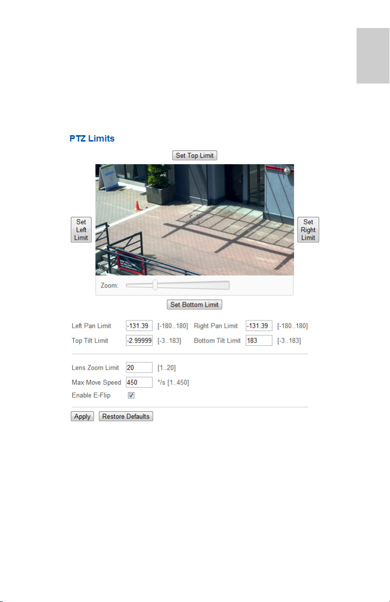
PTZ Limits
Depending on where the PTZ camera is installed, you may want to limit
the movement and zoom of the camera so that obstructions are never in
view. For example, if the PTZ camera is installed close to the side of a
building, you can set the limits so that the PTZ camera cannot move to
show the wall it is installed against.
1. Among the Setup options, click PTZ Limits.
English
2. To limit the maximum movement range, you can do one of the
following:
• In the image panel, move the PTZ camera to the farthest
point to its left that you want to display then click Set Left
Limit. Repeat for each direction. For information about
moving the PTZ camera, see Using the PTZ Camera
Controls on page 5.
• In the Pan and Tilt Limit text boxes, manually enter the limits.
Beside each field is the maximum range each setting can be.
3. To set the Lens Zoom Limit, enter a maximum zoom level.
23
Page 28

English
4. To set the Maximum Move Speed, enter a maximum number of
degrees per second.
5. To allow the camera to automatically correct the video image
when the camera tilts more than 90°, select the Enable E-Flip
check box. When this option is disabled, the video image is
upside down when the camera tilts more than 90°.
6. Click Apply to save your settings.
24
Page 29
Encoder
Avigilon H.264 encoders use many of the same settings as the cameras,
but the following settings are only available to encoders.
Selecting a Port or Channel Option
An encoder can have up to 4 cameras and 4 audio devices connected at
one time, so some pages in the web interface include a set of options for
each port or channel on the encoder.
On pages with live video options, like Live View and Motion Detection, you
can change the displayed camera by selecting a Port number from the
drop down list.
On setup pages without video, the options are divided by video port or
audio channel so that different options can be applied to each.
Enabling Video Input Termination
• To enable the video input termination, select a Port check
box on the General page.
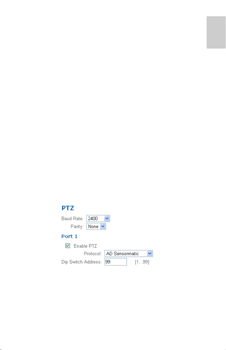
Setting Up PTZ
The H.264 encoders have pan, tilt and zoom (PTZ) setup options. Once
enabled, the Live View will display the PTZ controls for the camera.
1. Among the Setup options, click PTZ.
English
2. Select a Baud Rate and Parity.
3. For each port that is connected to a PTZ camera, select the
Enable PTZ check box.
4. Select a Protocol and enter a Dip Switch Address.
5. Click Apply.
6. To use the PTZ controls, see Using the Encoder PTZ Controls on
page 6.
25
Page 30

Page 31

Guide de l'utilisateur
Modèles de IP H.264 haute définition Avigilon :
H3-B1, H3-B2, H3-D1, H3-DC1, H3-DO1, H3-DP1, H3W-PTZ20
et ENC-4P-H264
Page 32

Copyright © 9/19/12 Avigilon. Tous droits réservés.
Aucune reproduction, distribution, publication, modification, ou incorporation de
tout ou partie de ce document n'est autorisée sans l'autorisation écrite expresse
d'Avigilon. En cas d'autorisation de reproduction, distribution, publication,
modification ou incorporation de ce document, aucune modification ou
suppression du crédit de l'auteur, de la légende des marques commerciales ou de
l'avis de droits de reproduction ne devra être effectuée. Aucune partie de ce
document ne peut être reproduite, stockée sur un système de récupération,
publiée, exploitée à des fins commerciales ou transmise, sous quelque forme que
ce soit, par quelque moyen que ce soit, notamment mais sans s'y limiter, le
support électronique ou mécanique, la photocopie ou l'enregistrement, sans
l'autorisation écrite expresse d'Avigilon.
Windows et Internet Explorer sont des marques commerciales de Microsoft Inc..
Mac, Apple et Safari sont des marques commerciales d'Apple Inc..
iOS est une marque commerciale de Cisco cédée sous licence à Apple..
Opera est une marque commerciale d'Opera Software ASA.
Android et Chrome sont dees marques commerciales de Google Inc..
Avigilon s'efforce autant que faire se peut d'identifier les propriétés faisant l'objet
d'une marque commerciale ainsi que leurs propriétaires sur cette page. Toutes les
marques et noms de produit utilisés dans ce document y figurent à des fins
informatives uniquement et peuvent constituer des marques commerciales ou des
marques déposées de leurs propriétaires respectifs.
Avigilon
Téléphone : +1.604.629.5182
Télécopie : +1.604.629.5183
http://www.avigilon.com
Révisé 9/19/12
Page 33

Tables des matières
Introduction . . . . . . . . . . . . . . . . . . . . . . . . . . . . . . . . . 1
Configuration système requise . . . . . . . . . . . . . . . . . . . . . 1
Accès à l'interface Web de la caméra . . . . . . . . . . . . 2
Vue du direct . . . . . . . . . . . . . . . . . . . . . . . . . . . . . . . . 3
Utilisation des commandes de zoom et de mise au point de la
caméra . . . . . . . . . . . . . . . . . . . . . . . . . . . . . . . . . . . . . . 3
Utilisation des réglages prédéfinis de caméra . . . . . . . . . . 4
Utilisation des commandes de caméra PTZ . . . . . . . . . . . 4
Utilisation des commandes PTZ de l'encodeur . . . . . . . . . 6
Configuration . . . . . . . . . . . . . . . . . . . . . . . . . . . . . . .8
Général . . . . . . . . . . . . . . . . . . . . . . . . . . . . . . . . . . . . . . . 8
Réseau . . . . . . . . . . . . . . . . . . . . . . . . . . . . . . . . . . . . . . . 9
Image et affichage . . . . . . . . . . . . . . . . . . . . . . . . . . . . . . 11
Débit image et vitesse compression . . . . . . . . . . . . . . . . 14
Configuration de l'URI du flux RTSP . . . . . . . . . 15
Détection de mouvements . . . . . . . . . . . . . . . . . . . . . . . . 16
Zones privées . . . . . . . . . . . . . . . . . . . . . . . . . . . . . . . . . 17
Entrées et sorties numériques . . . . . . . . . . . . . . . . . . . . . 18
Microphone . . . . . . . . . . . . . . . . . . . . . . . . . . . . . . . . . . . 19
Haut-parleur . . . . . . . . . . . . . . . . . . . . . . . . . . . . . . . . . . 19
Utilisateurs . . . . . . . . . . . . . . . . . . . . . . . . . . . . . . . . . . . . 20
Ajout d'un utilisateur . . . . . . . . . . . . . . . . . . . . . 20
Modification des utilisateurs
et des mots de passe. . . . . . . . . . . . . . . . . . . . . 21
Système . . . . . . . . . . . . . . . . . . . . . . . . . . . . . . . . . . . . . 21
Mise à niveau du microcode de la caméra . . . . 22
Journal du périphérique . . . . . . . . . . . . . . . . . . . . . . . . . . 22
Français
Caméra PTZ . . . . . . . . . . . . . . . . . . . . . . . . . . . . . . . . 23
Tours de garde PTZ . . . . . . . . . . . . . . . . . . . . . . . . . . . . 23
Modification des tours de garde PTZ . . . . . . . . 25
Limites PTZ . . . . . . . . . . . . . . . . . . . . . . . . . . . . . . . . . . . 25
Encodeur . . . . . . . . . . . . . . . . . . . . . . . . . . . . . . . . . .28
Sélection d'un port ou d'un canal . . . . . . . . . . . . . . . . . . 28
Activation de la fin d'entrée vidéo . . . . . . . . . . . . . . . . . . 28
Configuration PTZ . . . . . . . . . . . . . . . . . . . . . . . . . . . . . . 28
Page 34

Français
Page 35

Introduction
Toutes les caméras et caméras dôme Avigilon IP H.264 haute définition
contiennent une interface Web qui vous permet d'afficher de la vidéo en
direct et de configurer l'appareil par le biais d'un navigateur Web.
Avant d'accéder à l'interface Web de la caméra, veillez à effectuer toutes
les procédures décrites dans son guide d'installation.
Configuration système requise
L'interface Web de la caméra est accessible depuis tout équipement
Windows®, Mac® ou mobile au moyen d'un des navigateurs suivants :
• Navigateur Windows® Internet Explorer®, version 7.0 ou
ultérieure
®
• Navigateur Mozilla
• Navigateur Opera
• Navigateur Chrome ™ 8.0 ou ultérieure
• Navigateur Safari
• Navigateur Android™ 2.2 (Froyo) ou ultérieur
• Navigateur Apple
Firefox®, version 3.6 ou ultérieure
©
, version 9.0 ou ultérieure
®
, version 5.0 ou ultérieure
®
iOS, version 5.0 ou ultérieure
Français
1
Page 36

Accès à l'interface Web de la caméra
Une fois la caméra installée, pour accéder à son interface Web, vous
devez connaître son adresse IP. L'adresse IP de la caméra se trouve à un
Français
des emplacements suivants :
• Utilitaire d'installation de caméra Avigilon : cliquez sur le
bouton
à la caméra connectée.
•
Logiciel Avigilon Control Center Client : ouvrez la boîte de
dialogue de configuration de la caméra pour afficher les
détails relatifs à la caméra sélectionnée.
Une fois que vous disposez de l'adresse IP de la caméra, effectuez la
procédure suivante pour accéder à l'interface Web de la caméra :
1. Sur un ordinateur doté d'un accès à Internet, saisissez l'adresse
IP de la caméra dans un navigateur Web :
http://<Adresse IP de la caméra>/
Par exemple, http://192.168.1.40/
2. Vous êtes automatiquement invité à saisir votre nom d'utilisateur
et votre mot de passe pour accéder à la caméra.
Le nom d'utilisateur est admin, et le mot de passe par défaut
admin. Nous vous recommandons de changer le mot de passe
par défaut dès votre première connexion. Pour plus
d'informations, reportez-vous à la section Modification des
utilisateurs et des mots de passe en page 21.
Connecter à caméra pour afficher les détails relatifs
REMARQUE : Vous ne pouvez modifier le mot de passe de la caméra
que dans l'interface Web. Vous ne pouvez pas modifier le
mot de passe de la caméra dans le logiciel de gestion des
vidéos en réseau (NVMS).
2
Page 37

Vue du direct
Une fois connecté à la caméra, la première page qui s'affiche présente la
vue du direct de la caméra. La vue du direct contient un panneau
d'images. Il affiche le flux vidéo de la caméra.
Les liens du menu du coin supérieur droit ouvre chacune des pages de
l'interface Web. Pour revenir à la présente page à tout moment, cliquez
sur Vue du direct (Live View).
Français
Les sections qui suivent décrivent les boutons susceptibles de s'afficher
sous le volet d'image si l'utilisateur a accès aux commandes PTZ. Pour
fournir à l'utilisateur des commandes PTZ, reportez-vous à la section
Ajout d'un utilisateur en page 20.
Utilisation des commandes de zoom et de mise au point de la caméra
• Pour effectuer un zoom arrière, cliquez sur << pour utiliser
un pas important, ou sur
< pour un pas plus restreint.
3
Page 38

• Pour effectuer un zoom avant, cliquez sur >> pour utiliser un
pas important, ou sur
> pour un pas plus restreint.
• Pour une mise au point (Focus) vers zéro, cliquez sur
< pour un pas plus
> pour un pas plus
Français
pour utiliser un pas important, ou sur
restreint.
• Pour une mise au point (Focus) vers l'infini, cliquez sur
pour utiliser un pas important, ou sur
restreint.Utilisation des réglages prédéfinis de caméra.
Utilisation des réglages prédéfinis de caméra
1. Sur la page Vue directe (Live View), utilisez les commandes de
zoom et de mise au point pour focaliser la caméra sur un point
spécifique de l'image vidéo.
2. Pour ajouter cette position de caméra en tant que réglage
prédéfini, saisissez un nom dans le champ Ajouter un réglage
prédéfini (Add Preset), puis cliquez sur Ajouter (Add).
3. Pour utiliser un réglage prédéfini, sélectionnez-le dans la liste
déroulante Réglages prédéfinis, puis cliquez sur Valider (Go).
4. Pour supprimer un réglage prédéfini, sélectionnez-le dans la liste
déroulante, puis cliquez sur Supprimer (Remove).
Les réglages prédéfinis sont également configurables dans le logiciel
Avigilon Control Center Client à l'aide des commandes PTZ.
<<
>>
Utilisation des commandes de caméra PTZ
Si vous avez accès à une caméra PTZ (Pan-Tilt-Zoom; panoramique,
inclinaison, zoom) autonome, vous pouvez contrôler la mise au point et
les réglages prédéfinis de la même manière qu'avec toute autre caméra.
Parallèlement, vous avez alors accès à d'autres fonctions spécifiques à ce
type de caméras.
4
Page 39

1. Pour effectuer un zoom :
• Réglez le curseur Zoom.
• Ou, cliquez puis faites glisser un cadre vert sur le volet
d'image afin de délimiter la zone sur laquelle vous souhaitez
effectuer le zoom.
2. Pour déplacer la caméra :
• Cliquez sur un point dans le volet d'image pour centrer la
caméra sur cet emplacement.
• Ou, faites glisser le pointeur de la souris en partant du
centre pour déplacer la caméra dans la direction esquissée.
Plus le pointeur s'éloigne du centre, plus la caméra se
déplace rapidement.
3. Pour effectuer un tour de garde, sélectionnez-le dans la liste
déroulante, puis cliquez sur Démarrer (Start). Pour configurer un
tour de garde, reportez-vous à la section Tours de garde PTZ en
page 23.
4. Pour arrêter un tour de garde, cliquez sur Arrêter (Stop). Vous
pouvez interrompre un tour de garde à tout moment, en utilisant
simplement les autres commandes PTZ.
Français
5
Page 40

Utilisation des commandes PTZ de l'encodeur
Vous pouvez activer l'option PTZ sur toute caméra connectée à un
encodeur H.264. Une fois cette option activée, les commandes PTZ
s'affichent dans la Vue du direct de la caméra.
Pour activer les commandes PTZ de caméras connectées à un encodeur,
Français
consultez la section Configuration PTZ en page 28.
1. Sélectionnez une caméra dans la liste déroulante Port.
REMARQUE : Les commandes PTZ se présentent uniquement lorsque la
caméra s'affiche d'elle-même.
2. Pour déplacer le champ de vision de la caméra, cliquez sur une
des touches directionnelles sur l'extrême gauche.
3. Pour contrôler le zoom, le diaphragme (Iris) et la mise au point
(Focus) de la caméra, cliquez sur les boutons + et -.
4. Les réglages prédéfinis autorisent les opérations suivantes :
• Pour ajouter un réglage prédéfini, mettez le champ de vision
de la caméra en position, puis nommez votre préréglage.
Cliquez ensuite sur Définir (Set).
• Pour utiliser un réglage prédéfini, sélectionnez son nom ou
son numéro dans la liste déroulante, puis cliquez sur Valider
(Go To).
5. Les schémas autorisent les opérations suivantes :
• Pour enregistrer un schéma, sélectionnez un numéro dans
la liste déroulante, puis cliquez sur Enregistrer (Record).
Utilisez les touches directionnelles pour déplacer la caméra
et créer le schéma. Une fois l'opération terminée, cliquez sur
Arrêter (Stop).
• Pour exécuter un schéma, sélectionnez un numéro dans la
liste déroulante, puis cliquez sur Exécuter (Run).
6
Page 41

6. Pour activer une commande auxiliaire, sélectionnez un numéro
Aux dans la liste déroulante, puis cliquez sur Démarrer (Start).
Une fois l'opération terminée, cliquez sur Arrêter (Stop).
Français
7
Page 42

Configuration
REMARQUE : Si vous ne disposez pas des autorisations utilisateur
requises, certaines des pages de configuration, voire leur
totalité, peuvent ne pas s'afficher.
Français
Les paramètres par défaut du dispositif vous permettent d'exploiter la
caméra ou l'encodeur immédiatement après son installation. Si vos
besoins sont particuliers, vous pouvez personnaliser les paramètres de la
caméra par le biais de l'interface Web.
Un bouton Restaurer valeurs par défaut (Restore Default)est disponible
sur chaque page de configuration. Il vous permet de restaurer les
paramètres d'origine.
N'oubliez pas que certains des paramètres ne sont accessibles que par le
biais de l'interface Web de la caméra et ne peuvent donc pas être
modifiés dans le logiciel NVMS.
Les pages de configuration suivantes sont issues de l'interface Web. Elles
sont communes à tous les dispositifs Avigilon H.264, sauf indication
contraire.
Pour les paramètres spécifiques aux caméras PTZ, reportez-vous à la
section Caméra PTZ en page 23.
Pour les paramètres spécifiques aux encodeurs, reportez-vous à la
section Encodeur en page 28.
Général
Lorsque vous sélectionnez le lien Configuration (Setup), la page Général
(General) s'affiche en premier. La page Général vous permet de définir
l'identité de la caméra.
8
Page 43

1. Dans le champ Nom (Name), donnez à la caméra un nom
descriptif qui facilitera son identification.
2. Dans le champ Emplacement (Location), décrivez
l'emplacement de la caméra.
3. Cochez la case Désactiver LED de statut de caméra (Disable
camera status LEDs) afin de désactiver les diodes, ou LED (Light
Emitting Diode), situées à l'arrière de la caméra.
4. Cliquez sur Appliquer (Apply).
Réseau
La page Réseau (Network) vous permet de modifier le mode de
connexion de la caméra au réseau sur lequel est installé le serveur ainsi
que la manière dont la caméra conserve l'heure.
REMARQUE : L'interface Web de la caméra vous permet également
définir le port HTTPS, le port RTSP et le serveur NTP.
1. Dans les zones Adresse et Nom d'hôte, sélectionnez la manière
dont la caméra obtient une adresse IP :
• Obtenir automatiquement une adresse IP (Obtain an IP
address automatically) : activez cette option pour que la
caméra se connecte au réseau par le biais d'une adresse IP
affectée automatiquement.
La caméra tente d'obtenir une adresse auprès d'un
serveur DHCP. Si elle n'y parvient pas, la caméra utilise par défaut une adresse de la plage 169.254.x.x.
• Utiliser adresse IP suivante (Use the following IP address)
: activez cette option pour affecter manuellement une
adresse IP statique à la caméra.
Saisissez les Adresse IP (IP Address), Masque de
sous-réseau (Subnet Mask) et Passerelle par défaut
(Default Gateway) que vous souhaitez utiliser pour la
caméra.
Français
2. Si vous devez personnaliser le nom d'hôte, saisissez-le dans le
champ Nom d'hôte (Hostname).
3. La zone Ports de contrôle vous permet de spécifier les ports de
contrôle utilisés pour accéder à la caméra. Vous pouvez saisir
n'importe quel numéro de port entre 1 et 65534. Les numéros de
port par défaut sont les suivants :
9
Page 44

Français
• Port HTTP : 80
• Port HTTPS : 443
• Port RTSP : 554
4. La zone Serveur NTP vous permet de sélectionner la manière
dont la caméra conserve l'heure. La caméra ne dispose d'aucune
horloge interne. Aussi, elle recourt à un serveur NTP (Network
Time Protocol) pour conserver l'heure.
• Obtenir un serveur NTP via DHCP (Obtain NTP server via
DHCP) : activez cette option afin que la caméra utilise
automatiquement le même serveur NTP que le reste du
réseau.
• Utiliser le serveur NTP suivant (Use the following NTP
server): activez cette option pour définir manuellement le
serveur NTP que la caméra utilisera.
5. Cliquez sur Appliquer (Apply) une fois que vous avez terminé.
10
Page 45

Image et affichage
REMARQUE : Cette page de configuration n'est pas disponible pour les
encodeurs. Certaines options sont indisponibles dès lors
que les caméras ne les prennent pas en charge.
La page Image et
affichage (Image and
Display) vous permet de
contrôler les paramètres
d'affichage vidéo de la
caméra.
La page Image et
affichage comprend un
panneau d'images. Il
affiche le flux vidéo de la
caméra. Lorsque vous
cliquez sur Appliquer
(Apply) pour enregistrer
vos modifications, le flux
vidéo est mis à jour.
Les caméras Avigilon
sont dotées de
commandes de zoom et
de mise au point
électriques. Elles vous
permettent de régler le
zoom et la mise au point
depuis cette page.
Français
1. Utilisez les commandes de zoom pour régler le positionnement
du zoom de la caméra.
2. Si la caméra dispose d'une fonction de mise au point
automatique (autofocus) intégrée, activez l'option Mise au point
continue (Continuous Focus) pour permettre à la caméra
d'effectuer elle-même la mise au point lorsque la scène change.
3. Pour régler manuellement la mise au point de la caméra,
sélectionnez Ouvrir (Open) dans la liste déroulante Diaphragme
(Iris), puis utilisez les boutons Mise au point (Focus) pour
effectuer le réglage.
Les boutons fléchés gauche effectuent la mise au point de la
caméra vers la valeur zéro (0), les boutons fléchés droits vers la
valeur infinie. Cliquez sur le bouton Autofocus (Auto Focus) pour
11
Page 46

que la caméra effectue automatiquement la mise au point une
fois.
REMARQUE : Une fois la mise au point effectuée manuellement, elle ne
change plus.
4. Pour régler l'image vidéo, modifiez un des paramètres suivants
selon les besoins.
Français
Option Description
Exposition
(Exposure)
Diaphragme
(Iris)
Filtre de coupure
IR
(IR Cut Filter)
Contrôle du
scintillement
(Flicker Control)
Compensation
rétro-éclairage
(Backlight
Compensation)
Exposition
maximum
(Maximum
Exposure)
Lorsque vous sélectionnez Automatique (Automatic),
la caméra peut contrôler l'exposition. Vous pouvez
également définir un taux d'exposition spécifique.
REMARQUE : Accroître la durée d'exposition
manuelle peut affecter le débit
d'images.
Lorsque vous sélectionnez Automatique, la caméra
peut contrôler le diaphragme. Vous pouvez
également affecter manuellement à ce réglage la
valeur Ouvert (Open) ou Fermé (Closed).
Lorsque vous sélectionnez Automatique, la caméra
peut contrôler le filtre de coupure IR. Vous pouvez
également affecter à la caméra le mode Couleur
(Color) ou Monochrome (Monochrome).
Si votre image vidéo scintille du fait de lampes
fluorescentes placées autour de la caméra, diminuez
l'effet de scintillement en appliquant au Contrôle du
scintillement la même fréquence qu'à vos lampes.
Cette fréquence est généralement de 50 Hz en
Europe et de 60 Hz en Amérique du Nord.
Si votre scène présente des zones de lumière intense
entraînant l'assombrissement excessif de l'ensemble
de l'image, modifiez la valeur Compensation rétroéclairage jusqu'à obtenir une image correctement
exposée.
Vous pouvez restreindre la valeur du paramètre
d'exposition automatique en sélectionnant un niveau
d'exposition maximal.
En fixant un niveau d'exposition maximal pour les
situations de faible luminosité, vous contrôlez la durée
d'exposition de la caméra de sorte à permettre le
captage de la quantité maximale de lumière sans
créer d'images floues.
12
Page 47

Option Description
Gain maximum
(Maximum Gain)
Priorité
(Priority)
Saturation Vous pouvez régler la saturation chromatique de la
Netteté
(Sharpness)
Luminosité
(Brightness)
Contraste
(Contrast)
Balance des
blancs
(White Balance)
Vous pouvez restreindre la valeur du paramètre de
gain automatique en sélectionnant un niveau de gain
maximal.
En fixant un niveau de gain maximal pour les
situations de faible luminosité, vous optimisez le détail
de l'image sans générer de bruit excessif.
Vous pouvez définir le paramètre Débit d'images
(Image Rate) ou Exposition (Exposure) en tant que
priorité.
Lorsque la priorité porte sur le Débit d'images, la
caméra préserve le débit d'images défini en tant que
priorité et ne règle pas l'exposition au-delà de ce que
le débit d'images défini est capable d'enregistrer.
Lorsque la priorité port sur l'Exposition, la caméra
préserve le niveau d'exposition défini en tant que
priorité sans dépasser le débit d'images défini pour
atteindre la meilleure qualité d'image possible.
vidéo en saisissant une valeur en pourcentage. 0 crée
une image en noir et blanc, 100 des images en
couleurs intenses.
Vous pouvez régler la netteté de la vidéo en
saisissant une valeur en pourcentage. 0 applique la
netteté la plus faible aux contours des objets pour les
rendre plus visibles, 100 la netteté la plus élevée.
Vous pouvez régler la luminosité de la vidéo en
saisissant une valeur en pourcentage. 0 crée une
image sombre, tandis que 100 crée une image
illuminée.
Vous pouvez régler le contraste de la vidéo en
saisissant une valeur en pourcentage. 0 applique le
contraste minimal, tandis que 100 applique le
contraste maximal.
Vous pouvez contrôler la balance des blancs pour
adapter la caméra aux différences de lumière.
Lorsque vous sélectionnez Automatique, la caméra
peut contrôler la balance des blancs. Vous pouvez
également sélectionner Personnalisé (Custom)et
régler manuellement les paramètres de Rouge (Red)
et de Bleu (Blue).
Français
13
Page 48

Option Description
WDR (PTZ
uniquement)
Français
Vous pouvez activer des réglages de couleur
automatiques grâce à la fonction WDR (Wide
Dynamic Range). Elle permet à la caméra d'adapter
l'image vidéo aux scènes dans lesquelles figure une
lumière ou une obscurité excessive.
Débit image et vitesse compression
La page Débit image et vitesse compression (Compression and Image
Rate) vous permet de modifier les paramètres de compression et de
qualité d'image pour l'acheminement de flux vidéo sur le réseau.
Pour faciliter l'accès et diminuer l'usage de la bande passante, l'interface
Web affiche le flux vidéo uniquement au format JPEG et ne permet pas
de changer cette configuration. Les paramètres de cette page affectent
uniquement la vidéo transmise au logiciel de gestion vidéo en réseau.
Les caméras Avigilon disposent de capacités de double flux. Aussi, même
si elles présentent un format de flux en H.264, l'interface Web peut tout de
même afficher une vidéo au format JPEG.
Toutefois, les caméras connectées à un encodeur Avigilon ne disposent
généralement pas d'une telle capacité. Aussi, une fois le format de flux
vidéo H.264 choisi, la vidéo en direct transmise par ces caméras ne
s'affiche plus dans l'interface Web.
REMARQUE : L'interface Web de la caméra ne permet de modifier que
les paramètres de flux RTSP.
1. Dans la liste déroulante Format, sélectionnez le format de
gestion de flux retenu pour l'affichage de la vidéo de la caméra au
niveau du NVMS.
14
Page 49

2. Dans le champ Débit d'images (Image Rate), saisissez une
valeur entre 1 et 30 pour spécifier le nombre d'images par
seconde que vous souhaitez voir acheminé en flux par la caméra
sur le réseau.
3. Dans la liste déroulante Qualité (Quality), sélectionnez le niveau
de qualité d'image souhaité.
Une valeur de qualité d'image de 1 produira la qualité vidéo la
plus élevée et sollicitera le plus de bande passante.
4. Dans le champ Débit maximal en bits (Max Bitrate), saisissez la
bande passante maximale que la caméra peut utiliser. Vous
pouvez saisir n'importe quelle valeur entre 256 et 12 000 kbits/s.
5. Dans la liste déroulante Résolution (Resolution), sélectionnez la
résolution d'image souhaitée.
6. Dans le champ Intervalle images clés (Keyframe Interval),
saisissez le nombre d'images présentes entre les images clés.
Vous pouvez saisir n'importe quelle valeur entre 2 et 64.
7. Cliquez sur Appliquer (Apply) pour enregistrer vos modifications.
Configuration de l'URI du flux RTSP
La page Débit image et vitesse compression (Compression and Image
Rate) vous permet également de configurer le protocole de gestion de
flux en temps réel RTSP (Real Time Streaming Protocol) de la caméra.
L'URI de gestion de flux RTSP vous permet de visionner le flux vidéo de
la caméra en direct depuis n'importe quelle application qui prend en
charge les flux RTSP, dont un grand nombre de lecteurs vidéo.
1. Pour définir le protocole, sélectionnez soit Unicast, soit Multicast
dans la zone URI de flux RTSP, puis cliquez sur Appliquer
(Apply).
2. Pour visionner le flux vidéo direct de la caméra depuis un lecteur
vidéo externe, cliquez sur Générer une URI de flux RTSP
(Generate RTSP Stream URI).
a. Copiez l'adresse générée, puis collez-la dans votre lecteur
vidéo. N'OUVREZ PAS le flux vidéo direct pour le moment.
Français
b. Ajoutez votre nom d'utilisateur et votre mot de passe au
début de l'adresse. Utilisez le format suivant :
rtsp://<nom_utilisateur>:<mot_de_passe>@<URI de flux RTSP générée>/
Par exemple : rtsp://admin:admin@192.168.1.79/
defaultPrimary?streamType=u
c. Ouvrez le flux vidéo en direct.
15
Page 50

Détection de mouvements
La page Détection de mouvements (Motion Detection) vous permet de
définir les zones de détection de mouvements vertes dans le champ de
vision de la caméra. La détection de mouvements n'est pas prise en
compte dans les zones qui ne sont pas mises en évidence en vert.
Pour faciliter la définition du seuil et de la sensibilité de mouvement, le
mouvement est mis en évidence en rouge dans le volet d'image.
Français
1. Par défaut, l'ensemble du champ de vision est mis en évidence
pour la détection de mouvement. Pour définir la zone de détection
de mouvement, utilisez un des outils suivants :
• Cliquez sur Tout vider (Clear All) pour éliminer toutes les
zones de détection de mouvement de l'image vidéo.
• Cliquez sur Définir tout (Set All) pour configurer la zone de
détection de mouvement afin qu'elle s'étende à l'intégralité
de l'image vidéo.
• Pour définir une zone de détection de mouvement
spécifique, cliquez sur Sélectionner zone (Select Area),
puis cliquez dans l'image vidéo et faites glisser le pointeur
de la souris.
• Pour supprimer une zone de détection de mouvement,
cliquez sur Effacer zone (Clear Area), puis cliquez dans
16
Page 51

l'image vidéo et faites glisser le pointeur afin de couvrir la
zone à supprimer.
• Utilisez les boutons de zoom avant et arrière pour localiser
des zones spécifiques dans l'image vidéo.
2. Dans le champ Sensibilité (Sensitivity), saisissez un
pourcentage afin de définir la proportion de changement de
chaque pixel pour que l'image soit considérée comme l'objet d'un
mouvement.
Plus la sensibilité est élevée, plus la proportion de changement
de pixels requise avant détection de mouvement est faible.
3. Dans le champ Seuil (Threshold), saisissez un pourcentage afin
de définir le nombre de pixels qui doivent changer avant que
l'image soit considérée comme l'objet d'un mouvement.
Plus le seuil est élevé, plus le nombre de pixels nécessaire pour
que l'image soit considérée comme l'objet d'un mouvement est
élevé.
4. Cliquez sur Appliquer (Apply) pour enregistrer vos modifications.
Zones privées
La page Zones privées (Privacy Zones) permet de définir des zones
privées dans le champ de vision de la caméra afin de bloquer les secteurs
que vous ne souhaitez ni visionner, ni enregistrer. La caméra prend en
charge jusqu'à quatre zones privées.
Français
17
Page 52

1. Pour ajouter une zone privée, cliquez sur Ajouter (Add). Un
cadre de zone privée grisé vient s'ajouter à l'image vidéo.
2. Pour définir la zone privée, procédez d'une des manières
suivantes :
a. Faites glisser le côté droit ou inférieur du cadre grisé pour
redimensionner la zone privée.
REMARQUE : Les zones privées sont uniquement rectangulaires.
Français
b. Cliquez au centre du cadre grisé, puis faites glisser le
pointeur de la souris pour déplacer la zone privée.
c. Cliquez sur le X placé dans le coin supérieur droit du cadre
grisé afin de supprimer la zone privée correspondante.
3. Cliquez sur Appliquer (Apply) pour enregistrer les paramètres de
la zone privée.
4. Si vous utilisez une caméra PTZ, une liste des zones privées est
disponible au bas de la page. Lorsque vous cliquez sur une des
zones privées, la caméra se déplace et met en évidence la zone
privée choisie dans le volet d'image.
Entrées et sorties numériques
La page Entrées et sorties numériques (Digital Inputs and Outputs) vous
permet de configurer les dispositifs d'entrée et de sortie externes
connectés à la caméra.
1. Dans la zone Entrées numériques (Digital Inputs), nommez
l'entrée numérique, puis sélectionnez l'état de circuit pour celleci.
18
Page 53

2. Dans la zone Sorties numériques (Digital Outputs), nommez la
sortie numérique, puis sélectionnez l'état de circuit pour celle-ci.
3. Dans le champ Durée (Duration) de la sortie numérique,
saisissez la durée d'activité de la sortie numérique une fois celleci déclenchée. Vous pouvez saisir n'importe quelle valeur entre
100 et 3 600 000 millisecondes.
4. Cliquez sur Déclencher (Trigger) pour déclencher manuellement
la sortie numérique à partir de l'interface Web.
5. Cliquez sur Appliquer (Apply) pour enregistrer vos modifications.
Microphone
Si un micro est connecté à la caméra, vous pouvez en régler le gain dans
la page Microphone. Plus la valeur de gain est élevée, plus le volume du
micro sera élevé.
Français
• Saisissez une valeur entre 0 et 31 pour régler le gain du
micro, puis cliquez sur
Appliquer (Apply).
Haut-parleur
Si un micro est connecté à la caméra, vous pouvez en régler le volume
dans la page Haut-parleurs (Speakers).
• Saisissez une valeur entre 0 et 100 pour régler le volume
du haut-parleur, puis cliquez sur
Appliquer (Apply).
19
Page 54

Utilisateurs
La page Utilisateurs (Users) vous permet d'ajouter ou de modifier des
utilisateurs, et de changer les mots de passe.
Français
Ajout d'un utilisateur
1. Dans la page Utilisateurs, cliquez sur Ajouter... (Add).
2. Dans la page Ajouter un utilisateur (Add User), saisissez un nom
d'utilisateur et un mot de passe pour le nouvel utilisateur.
3. Dans la liste déroulante Groupe de sécurité (Security Group),
sélectionnez les autorisations d'accès disponibles pour ce nouvel
utilisateur.
• Administrateur (Administrator) : accès intégral à toutes les
fonctions disponibles dans l'interface Web de la caméra, y
compris aux commandes PTZ.
• Opérateur (Operator) : accès à la Vue du direct et aux
commandes PTZ, mais accès restreint aux fonctions de
configuration. Le nouvel utilisateur a uniquement accès aux
pages Image et affichage, Débit image et vitesse
compression, Détection de mouvements, Zones privées,
Entrées et sorties numériques, Microphone et Haut-parleur.
• Utilisateur (User) : accès à la Vue du direct et aux
commandes PTZ, mais aucun accès aux pages de
configuration. Pour activer les commandes PTZ, cochez la
case Utiliser contrôles PTZ (Use PTZ Controls).
4. Cliquez sur Appliquer (Apply) pour ajouter l'utilisateur.
20
Page 55

Modification des utilisateurs et des mots de passe
1. Dans la page Utilisateurs (Users), sélectionnez un utilisateur
dans la liste Nom d'utilisateur, puis cliquez sur Modifier (Modify).
2. Pour modifier le mot de passe de l'utilisateur, saisissez un
nouveau mot de passe pour celui-ci.
3. Pour modifier le groupe de sécurité de l'utilisateur, sélectionnez
un groupe différent dans la liste déroulante Groupe de sécurité
(Security Group).
REMARQUE : Vous ne pouvez pas modifier le groupe de sécurité du
compte d'administrateur.
4. Cliquez sur Appliquer (Apply) pour enregistrer vos modifications.
Système
La page Système (System) vous permet de mettre manuellement à
niveau le microcode de la caméra, de réinitialiser celle-ci et de restaurer
tous ses paramètres par défaut d'usine.
Français
21
Page 56

Mise à niveau du microcode de la caméra
Pour mettre manuellement à niveau le microcode de la caméra,
téléchargez la version la plus récente du fichier
depuis le site Web d'Avigilon (
http://www.avigilon.com/support/
.bin du microcode
firmware) puis effectuez la procédure suivante :
1. Cliquez sur Parcourir (Browse) puis localisez le fichier de
Français
microcode téléchargé.
2. Cliquez sur Mettre à niveau (Upgrade). Attendez que la mise à
niveau de la caméra soit terminée.
Journal du périphérique
La page Journal du périphérique (Device Log) vous permet d'afficher les
journaux système et d'accès de la caméra.
1. Dans la liste déroulante Type, sélectionnez soit les Journaux
d'accès, soit les Journaux système.
2. Dans la liste déroulante Niveau de journalisation minimal
(Minimum Log Level), sélectionnez les messages de journal que
vous souhaitez afficher.
3. Dans la liste déroulante Nombre de journaux maximal
(Maximum Number of Logs), sélectionnez le nombre de
messages de journal que vous souhaitez afficher à chaque fois.
4. Cliquez sur Mettre à jour (Update). Les journaux s'affichent audessous.
22
Page 57

Caméra PTZ
Les caméras PTZ Avigilon H.264 utilisent de nombreux paramètres
identiques à ceux des autres caméras. Les paramètres suivants sont
réservés aux caméras PTZ.
Tours de garde PTZ
Les caméras PTZ permettent d'exécuter un tour de garde dans la page
Vue du direct (Live View). Ces tours de garde permettent à la caméra
PTZ de se déplacer automatiquement en suivant une série de positions
prédéfinies. Ils permettent également de marquer des pauses d'une
durée spécifique sur chacune de ses positions à des fins de surveillance
vidéo.
Pour créer un tour de garde, procédez de la manière suivante :
REMARQUE : Toutes les positions prédéfinies requises doivent être
ajoutées avant la création du tour de garde. Pour plus
d'informations, reportez-vous à la section Utilisation des
réglages prédéfinis de caméra en page 4.
1. Parmi les options de configuration, cliquez sur Tours de garde
PTZ (PTZ Tours).
Français
23
Page 58

Français
2. Cliquez sur Créer un tour de garde (Create New Tour).
3. Nommez le tour de garde.
4. Dans la liste déroulante Mode, sélectionnez un des éléments
suivants :
• Séquentiel (Sequential): la caméra PTZ adopte les
positions prédéfinies dans l'ordre spécifié.
• Aléatoire (Random) : la caméra PTZ adopte les positions
prédéfinies au hasard.
5. Cochez la case Définir en tant que tour de garde par défaut (Set
as default tour), si vous souhaitez que ce tour de garde s'exécute
automatiquement.
• Le champ Heure de début d'inactivité de tour de garde par
défaut (Default Tour idle Start Time) est à présent activé.
Saisissez la durée d'inactivité de la caméra PTZ avant que le
tour de garde se déclenche automatiquement.
6. Pour ajouter une position prédéfinie, cliquez sur Ajouter un
réglage prédéfini (Add Preset). La position s'ajoute à la liste.
a. Dans la colonne Prédéfini (Preset), sélectionnez une
position prédéfinie dans la liste déroulante.
24
Page 59

b. Dans la colonne Vitesse de déplacement (Move Speed),
saisissez la vitesse à laquelle vous souhaitez que la caméra
PTZ se déplace vers la position prédéfinie choisie. Par
défaut, la vitesse est de 80%.
c. Dans la colonne Durée de visionnage (View Time), saisissez
la durée pendant laquelle vous souhaitez que la caméra
PTZ reste sur cette position prédéfinie. Par défaut, cette
durée est de 10 secondes.
d. Poursuivez la procédure jusqu'à ce que tous les réglages
prédéfinis relatifs à ce tour de garde aient été ajoutés.
7. Pour supprimer une position prédéfinie, cliquez sur l'icone (x)
placée à l'extrême droite de la position à supprimer.
8. Pour réorganiser les positions prédéfinies, cliquez sur les flèches
montantes et descendantes appropriées, ou cliquez sur une
position à déplacer, puis faites glisser son bord gauche dans la
liste.
9. Cliquez sur Appliquer (Apply) pour enregistrer le tour de garde.
Modification des tours de garde PTZ
1. Parmi les options de configuration, cliquez sur Tours de garde
PTZ (PTZ Tour).
2. Cliquez sur Modifier (Edit).
3. Effectuez les modifications dont vous avez besoin.
4. Pour annuler les modifications effectuées, cliquez sur Supprimer
les modifications (Discard Changes).
5. Cliquez sur Appliquer (Apply) pour enregistrer vos modifications.
6. Pour supprimer le tour de garde, cliquez sur Supprimer le tour
de garde (Delete Tour). Lorsque la boîte de dialogue
Confirmation s'affiche, cliquez sur OK.
Français
Limites PTZ
Selon l'endroit où la caméra PTZ est installée, vous pouvez souhaitez
limiter ses mouvements ainsi que son zoom afin qu'aucun obstacle
éventuel ne soit jamais présent dans le champ de vision. Par exemple, si
la caméra PTZ est installée à proximité d'un côté de bâtiment, vous
pouvez fixer les limites de sorte que la caméra ne puisse pas se tourner
face au mur sur lequel elle est installée.
25
Page 60

Français
1. Parmi les options de configuration, cliquez sur Limites PTZ (PTZ
Limits).
2. Pour limiter la plage de mouvement maximale, procédez d'une
des manières suivantes :
• Dans le volet d'image, déplacez la caméra PTZ jusqu'au
point le plus éloigné sur la gauche que vous souhaitez
visionner. Arrêtez-vous à cette extrémité choisie, puis
cliquez sur Définir limite gauche (Set Left Limit). Répétez
l'opération pour chaque direction. Pour plus d'informations
sur le déplacement de la caméra PTZ, reportez-vous à la
section Utilisation des commandes de caméra PTZ en
page 4.
• Dans le champ de saisie Limite de panoramique (Set Pan
Limit) et d'inclinaison (Set Tilt Limit), saisissez
manuellement les limites. En regard de chaque champ figure
la plage maximale qu'autorise chaque paramètre.
3. Pour fixer la valeur Limite de zoom d'objectif (Lens Zoom Limit),
saisissez un niveau de zoom maximal.
26
Page 61

4. Pour définir la valeur Vitesse de déplacement maximale
(Maximum Move Speed), saisissez une valeur maximale
exprimée en degrés par seconde.
5. Pour permettre à la caméra de corriger automatiquement l'image
vidéo en cas d'inclinaison de l'appareil à plus de 90°, cochez la
case Activer fonction E-Flip (Enable E-Flip). Lorsque cette
option est désactivée, l'image vidéo s'affiche à l'envers si la
caméra s'incline au-delà de 90°.
6. Cliquez sur Appliquer (Apply) pour enregistrer vos paramètres.
Français
27
Page 62

Encodeur
Les encodeurs Avigilon H.264 utilisent de nombreux paramètres
identiques à ceux des caméras. Toutefois, les paramètres suivants sont
propres aux seuls encodeurs.
Français
Sélection d'un port ou d'un canal
Un encodeur peut gérer jusqu'à 4 caméras et 4 périphériques audio
connectés simultanément. Aussi, certaines pages de l'interface Web
comprennent un jeu d'options destiné aux différents ports et canaux de
l'encodeur.
Sur les pages qui présentent des options de vidéo en direct, notamment
Vue du direct (Live View) et Détection de mouvement (Motion Detection),
vous pouvez modifier la caméra affichée en sélectionnant un numéro de
Port dans la liste déroulante.
Sur les pages de configuration sans vidéo, les options sont réparties par
port vidéo et canal audio. Ainsi différentes options peuvent s'appliquer à
chacun d'eux.
Activation de la fin d'entrée vidéo
• Pour activer la fin d'entrée vidéo, cochez une case Port
dans la page Général (General).
Configuration PTZ
Les encodeurs H.264 disposent d'options PTZ (Pan, Tilt, Zoom ;
panoramique, inclinaison, zoom). Une fois activée, la Vue du direct (Live
View) affiche les commandes PTZ pour la caméra.
1. Parmi les options de configuration, cliquez sur PTZ.
28
Page 63

2. Sélectionnez un Débit en bauds (Baud Rate) et une Parité
(Parity).
3. Pour chaque port connecté à une caméra PTZ, cochez la case
Activer PTZ (Enable PTZ).
4. Sélectionnez un Protocole (Protocol), puis saisissez une
Adresse commutateur (Dip Switch Address).
5. Cliquez sur Appliquer (Apply).
6. Pour utiliser les commandes PTZ, reportez-vous à la section
Utilisation des commandes PTZ de l'encodeur en page 6.
Français
29
Page 64

Page 65

Guía del usuario
IP H.264 de alta definición de Avigilon modelos:
H3-B1, H3-B2, H3-D1, H3-DC1, H3-DO1, H3-DP1, H3W-PTZ20 y ENC-4P-H264
Page 66

Copyright © 9/20/12 Avigilon. Reservados todos los derechos.
No se permite la copia, distribución, publicación, modificación o incorporación de
este documento, total o parcial, sin el permiso expreso por escrito de Avigilon. En
el caso de que se permita la copia, distribución, publicación, modificación o
incorporación de este documento, no se realizará ningún cambio ni eliminación
de la atribución de autoría, leyenda de marca comercial o aviso de copyright.
Ninguna parte de este documento podrá ser reproducida, almacenada en un
sistema de recuperación, publicada, usada para explotación comercial ni
transmitida, de ninguna forma y por ningún medio, electrónico, mecánico,
fotocopia, grabación y otros medios, sin la autorización expresa por escrito de
Avigilon.
Windows e Internet Explorer son marcas comerciales de Microsoft Inc.
Mac, Apple y Safari son marcas comerciales de Apple Inc.
iOS es una marca comercial de Cisco autorizada a Apple.
Opera es una marca comercial de Opera Software ASA.
Android y Chrome son marcas comerciales de Google Inc.
Avigilon ha hecho todo lo posible para identificar las propiedades y propietarios
con marca comercial en esta página. Todas las marcas y nombres de productos
utilizados en este documento solo son con fines de identificación y pueden ser
marcas comerciales o marcas comerciales registradas de sus empresas
respectivas.
Avigilon
Tel +1.604.629.5182
Fax +1.604.629.5183
http://www.avigilon.com
Revisado 9/20/12
Page 67

Tabla de Contenidos
Introducción . . . . . . . . . . . . . . . . . . . . . . . . . . . . . . . . 1
Requisitos del sistema . . . . . . . . . . . . . . . . . . . . . . . . . . . 1
Acceso a la interfaz web de la cámara . . . . . . . . . . . 2
Live View . . . . . . . . . . . . . . . . . . . . . . . . . . . . . . . . . . . 3
Usar los controles de enfoque y zoom de la cámara . . . . 3
Usar valores predeterminados de la cámara . . . . . . . . . . 4
Usar los controles de la cámara PTZ . . . . . . . . . . . . . . . . 4
Usar los controles PTZ del codificador . . . . . . . . . . . . . . . 6
Configuración . . . . . . . . . . . . . . . . . . . . . . . . . . . . . . . 7
General . . . . . . . . . . . . . . . . . . . . . . . . . . . . . . . . . . . . . . . 7
Red . . . . . . . . . . . . . . . . . . . . . . . . . . . . . . . . . . . . . . . . . . 8
Imagen y visualización . . . . . . . . . . . . . . . . . . . . . . . . . . . 9
Compresión y frecuencia de actualización de la imagen 12
Configuración de la URI de flujo RTSP . . . . . . . 13
Detección de movimiento . . . . . . . . . . . . . . . . . . . . . . . . 14
Zonas de privacidad . . . . . . . . . . . . . . . . . . . . . . . . . . . . 15
Entradas y salidas digitales . . . . . . . . . . . . . . . . . . . . . . . 17
Micrófono . . . . . . . . . . . . . . . . . . . . . . . . . . . . . . . . . . . . . 17
Altavoz . . . . . . . . . . . . . . . . . . . . . . . . . . . . . . . . . . . . . . . 18
Usuarios . . . . . . . . . . . . . . . . . . . . . . . . . . . . . . . . . . . . . 18
Adición de un usuario . . . . . . . . . . . . . . . . . . . . 18
Edición de usuarios y contraseñas . . . . . . . . . . 19
Sistema . . . . . . . . . . . . . . . . . . . . . . . . . . . . . . . . . . . . . . 20
Actualización del firmware de la cámara . . . . . 20
Registro de dispositivos . . . . . . . . . . . . . . . . . . . . . . . . . 21
Español
Cámara PTZ . . . . . . . . . . . . . . . . . . . . . . . . . . . . . . . . 22
Rondas de PTZ . . . . . . . . . . . . . . . . . . . . . . . . . . . . . . . . 22
Editar rondas de PTZ . . . . . . . . . . . . . . . . . . . . 24
Límites de PTZ . . . . . . . . . . . . . . . . . . . . . . . . . . . . . . . . 24
Codificador . . . . . . . . . . . . . . . . . . . . . . . . . . . . . . . . 26
Seleccionar un puerto u opción de canal . . . . . . . . . . . . 26
Activar finalización de entrada de vídeo . . . . . . . . . . . . . 26
Configurar PTZ . . . . . . . . . . . . . . . . . . . . . . . . . . . . . . . . 26
Page 68

Español
Page 69

Introducción
Todas las cámaras y cámaras domo IP H.264 de alta definición de
Avigilon contienen una interfaz web que le permite ver vídeo en tiempo
real y configurar la cámara a través de un navegador web.
Antes de acceder a la interfaz web de la cámara, asegúrese de completar
todos los procedimientos descritos en la guía de instalación de la
cámara.
Requisitos del sistema
A la interfaz web de la cámara se puede acceder desde cualquier
dispositivo Windows®, Mac® o móvil usando uno de los navegadores
siguientes:
• Navegador Windows® Internet Explorer® versión 7.0 o
posterior
®
• Navegador Mozilla
• Navegador Opera
• Navegador Chrome™ 8.0 o posterior
Firefox® versión 3.6 o posterior
©
9.0 o posterior
Español
®
• Navegador Safari
• Navegador Android™ 2.2 (Froyo) o posterior
• Navegador Apple
5.0 o posterior
©
iOS 5.0 o posterior
1
Page 70

Acceso a la interfaz web de la cámara
Una vez instalada la cámara, necesita la dirección IP de la cámara para
acceder a la interfaz web. La dirección IP de la cámara se puede
encontrar en uno de los lugares siguientes:
• Avigilon Camera Installation Tool: haga clic en el botón
Conectar a cámara para ver los detalles de la cámara
conectada.
•
Avigilon Control Center Client: abra el cuadro de diálogo
Español
Cuando disponga de la dirección IP de la cámara, complete el
procedimiento siguiente para acceder a la interfaz web de la cámara:
Configuración para ver los detalles de la cámara
seleccionada.
1. En un ordenador con acceso a Internet, introduzca la dirección IP
de la cámara en un navegador web:
http://<dirección IP de la cámara>/
Por ejemplo, http://192.168.1.40/
2. Se le pedirá automáticamente que introduzca su nombre de
usuario y su contraseña para acceder a la cámara.
El nombre de usuario predeterminado de la cámara es admin y
la contraseña predeterminada es admin. Se recomienda que
cambie la contraseña predeterminada después de su primer
inicio de sesión. Para obtener más información, consulte Edición
de usuarios y contraseñas en la página 19.
NOTA: Solo puede cambiar la contraseña de la cámara en la interfaz
web. La contraseña de la cámara no se puede cambiar en el
software de gestión de vídeo de la red.
2
Page 71

Live View
Después del inicio de sesión, la primera página que se ve es la vista en
tiempo real de la cámara. Live View contiene un panel de imágenes que
muestra el flujo de vídeo en tiempo real de la cámara.
Los enlaces de menú en la esquina superior izquierda le llevan a cada
una de las páginas de la interfaz web. Haga clic en Live View en
cualquier momento para volver a esta página.
Español
En las secciones siguientes se describen los botones que se pueden
mostrar debajo del panel de imágenes si los usuarios tienen acceso a los
controles PTZ. Para dar a un usuario controles PTZ, consulte Adición de
un usuario en la página 18.
Usar los controles de enfoque y zoom de la cámara
• Para alejarse, haga clic en << para dar un paso grande o en
< para dar un paso pequeño.
3
Page 72

• Para acercarse, haga clic en >> para dar un paso largo o en
> para dar un paso pequeño.
• Para enfocar hacia cero, haga clic en
largo o en
< para dar un paso pequeño.
• Para enfocar hacia el infinito, haga clic en
paso largo o en
> para dar un paso pequeño.
<< para dar un paso
>> para dar un
Usar valores predeterminados de la cámara
Español
1. En la página Vista en directo (Live View), utilice los controles de
zoom y enfoque para enfocar la cámara en un punto específico
de la imagen de vídeo.
2. Para añadir esta posición de la cámara como una preselección,
introduzca un nombre en el campo Agregar preselección (Add
Preset) y, a continuación, haga clic en Agregar (Add).
3. Para usar una preselección, seleccione una preselección
configurada en la lista desplegable Preselecciones (Preset) y
haga clic en Ir (Go).
4. Para eliminar una preselección, seleccione la que desea eliminar
en la lista desplegable y haga clic en Suprimir (Remove).
Las preselecciones también pueden configurarse en el software Avigilon
Control Center Client a través de los controles PTZ.
Usar los controles de la cámara PTZ
Si está accediendo a una cámara PTZ (desplazamiento horizontaldesplazamiento vertical-zoom) independiente, puede controlar las
opciones de enfoque y preselecciones de la misma forma que otras
4
Page 73

cámaras, pero también tendrá acceso a otras funciones específicas de la
cámara PTZ.
1. Para hacer zoom con la cámara:
• Ajuste el control deslizante Zoom.
• O bien, haga clic y arrastre para crear un cuadro verde en el
panel de imágenes para definir el área que desea acercar o
alejar.
2. Para mover la cámara:
• Haga clic en cualquier parte del panel de imágenes para
centrar la cámara en ese punto.
• O bien, arrastre el ratón desde el centro para desplazar la
cámara en esa dirección. Cuanto más aleje la flecha del
centro, con más rapidez se moverá la cámara.
3. Para realizar un control de rondas, seleccione un control en la
lista desplegable y, a continuación, haga clic en Iniciar (Start).
Para configurar una ronda, consulte Rondas de PTZ en la
página 22.
4. Para detener un control de rondas, haga clic en Detener (Stop).
Se puede hacer una pausa en una ronda en cualquier momento
al igual que con los otros controles PTZ.
Español
5
Page 74

Usar los controles PTZ del codificador
Cualquier cámara que esté conectada a un codificador H.264 puede
tener la opción PTZ habilitada. Cuando está habilitada, se muestran los
controles de desplazamiento horizontal, desplazamiento vertical y zoom
en la vista en directo para esa cámara.
Para habilitar el PTZ para aquellas cámaras conectadas a un codificador,
consulte Configurar PTZ en la página 26.
Español
1. Seleccione una cámara en la lista desplegable Puerto.
NOTA: Los controles PTZ solo se muestran cuando es la propia cámara
la que se muestra.
2. Para mover el campo de visión de la cámara, haga clic en uno de
los botones direccionales situados en el extremo izquierdo.
3. Para controlar el zoom, el diafragma (Iris) o el enfoque (Focus) de
la cámara, haga clic en los botones + o -.
4. Para las preselecciones, puede realizar cualquiera de las
siguientes acciones:
• Para agregar una preselección, desplace el campo de visión
de la cámara a la posición deseada, dé un nombre a la
preselección y haga clic en Establecer (Set).
• Para usar una preselección, seleccione un nombre o
número en la lista desplegable y haga clic en Ir a (Go To).
5. Para los patrones, puede realizar cualquiera de las siguientes
acciones:
• Para grabar un patrón, seleccione un número en la lista
desplegable y haga clic en Grabar (Record). Utilice los
botones direccionales para desplazar la cámara y crear el
patrón. Cuando haya terminado, pulse Detener (Stop).
• Para ejecutar un patrón, seleccione un número en la lista
desplegable y haga clic en Ejecutar (Run).
6. Para activar un comando auxiliar, seleccione un número de
auxiliar en la lista desplegable y haga clic en Iniciar (Start).
Cuando haya terminado, haga clic en Detener (Stop).
6
Page 75

Configuración
NOTA: Es posible que no se muestren algunas o todas las páginas de
Configuración si no tiene los permisos de usuario requeridos.
Los ajustes predeterminados de fábrica del dispositivo le permiten usar la
cámara o codificador inmediatamente después de la instalación. Si tiene
requisitos especiales, puede personalizar los ajustes de la cámara a
través de la interfaz web de la cámara.
En cada página de configuración está disponible un botón Restaurar
Predeterminados (Restore Default) que le permite restablecer los
ajustes predeterminados de fábrica.
Tenga presente que algunos ajustes solo están disponibles a través de la
interfaz web de la cámara y no se pueden cambiar en el software de
gestión de vídeo de red.
Las siguientes páginas de configuración de la interfaz web son comunes
en todos los dispositivos Avigilon H.264 a no ser que se indique otra
cosa.
Para obtener información sobre los ajustes específicos de las cámaras
PTZ, consulte Cámara PTZ en la página 22.
Para obtener información sobre los ajustes específicos de los
codificadores, consulte Codificador en la página 26.
Español
General
Cuando selecciona el enlace Configuración, la primera página que ve es
la página General. La página General le permite configurar la identidad
de la cámara.
7
Page 76

1. En el campo Nombre (Name), dé a la cámara un nombre
significativo que le ayude a identificar la cámara.
2. En el campo Ubicación (Location), describa la localización de la
cámara.
3. Seleccione la casilla Desactivar los LED de estado de la
cámara (Disable Camera Status LEDs) para deshabilitar los LED
situados en la parte trasera de la cámara.
4. Haga clic en Aplicar (Apply).
Red
En la página Red (Network), puede cambiar cómo se conecta la cámara
a la red del servidor y elegir cómo la cámara establece la hora.
NOTA: Solo puede establecer el puerto HTTPS, el puerto RTSP y el
Español
servidor NTP en la interfaz web de la cámara.
1. En el área Dirección y Nombre de host, seleccione cómo obtiene
la cámara la dirección IP:
• Obtener una dirección IP automáticamente (Obtain an IP
address automatically): seleccione esta opción para que la
cámara se conecte a la red mediante una dirección IP
automáticamente asignada.
La cámara intentará obtener una dirección desde un servidor DHCP. Si no puede, la cámara obtendrá de manera predeterminada las direcciones en el rango 169.254.x.x.
• Usar la siguiente dirección IP (Use the following IP
address): seleccione esta opción para asignar manualmente
una dirección IP estática a la cámara.
Introduzca la Dirección IP (IP Address), Máscara de
subred (Subnet Mask) y Puerta de enlace predeterminada (Default Gateway) que desee que use la cámara.
2. Si necesita personalizar el nombre de host, especifíquelo en el
campo Nombre de host (Hostname).
3. En el área Puerto de control, puede especificar qué puertos de
control se usan para acceder a la cámara. Puede introducir
cualquier número de puerto entre 1 y 65534. Los números de
puerto predeterminados son los siguientes:
• Puerto HTTP: 80
• Puerto HTTPS: 443
8
Page 77

• Puerto RTSP: 554
4. En el área Servidor NTP, seleccione cómo la cámara va a
establecer la hora. La cámara no tiene un reloj interno, por tanto
usa un servidor de protocolo de hora de red (NTP) para
establecer la hora.
• Obtener un servidor NTP a través de DHCP (Obtain NTP
server via DHCP): seleccione esta opción para que la
cámara utilice automáticamente el mismo servidor NTP que
el resto de la red.
• Usar el siguiente servidor NTP (Use the following NTP
server): seleccione esta opción para establecer
manualmente qué servidor NTP utilizará la cámara.
5. Haga clic en Aplicar (Apply) cuando haya finalizado.
Imagen y visualización
NOTA: Esta página de configuración no está disponible para
codificadores y algunas opciones no están disponibles si no las
admite la cámara.
En la página Imagen y
visualización (Image and
Display), puede controlar
los ajustes de visualización
de vídeo de la cámara.
La página Imagen y
visualización incluye un
panel de imágenes que
muestra el flujo de vídeo
en directo de la cámara.
Cuando haga clic en
Aplicar (Apply) para
guardar los cambios, el
flujo de vídeo se actualiza.
Las cámaras Avigilon
disponen de controles de
enfoque y zoom
electrónicos, por tanto
puede establecer el zoom y
el enfoque de la cámara
también desde esta
página.
Español
9
Page 78

1. Utilice los controles de zoom para ajustar la posición de zoom de
la cámara.
2. Si la cámara tiene una función de enfoque automático
incorporada, puede seleccionar la opción Enfoque continuo
(Continuous Focus) para permitir que la cámara se enfoque
siempre que cambie la escena.
3. Para enfocar manualmente la cámara, seleccione Abrir (Open)
en la lista desplegable Diafragma (Iris) y después utilice los
botones Enfoque (Focus) para enfocar la cámara.
Los botones de flecha izquierda enfocan la cámara hacia el cero
(0) y los botones de flecha derecha enfocan la cámara hacia el
infinito. Haga clic el botón Enfoque automático (Auto Focus)
que la cámara enfoque automáticamente una vez.
NOTA: Una vez el enfoque se establece manualmente, no cambiará.
Español
4. Para ajustar la imagen de vídeo, realice cambios en cualquiera
de los ajustes siguientes cuando se necesite.
Opción Descripción
Exposición
(Exposure)
Diafragma
(Iris)
Filtro ICR
(IR Cut Filter)
Control de
parpadeo
(Flicker Control)
Puede permitir que la cámara controle la exposición
seleccionando Automático (Automatic) o establecer
una velocidad de exposición específica.
NOTA: El aumento del tiempo de la exposición
manual puede afectar a la frecuencia de
actualización de imagen.
Puede permitir que la cámara controle el diafragma
seleccionando Automático (Automatic) o puede
establecerlo manualmente en Abierto (Open) o
Cerrado (Closed).
Puede optar por que la cámara controle el filtro ICR
seleccionando Automático o establecer la cámara
en modo Color o Monocromo (Monochrome).
Si la imagen de vídeo parpadea debido a las luces
fluorescentes que rodean la cámara, puede reducir
los efectos del parpadeo estableciendo el Control de
parpadeo en la misma frecuencia que las luces. Por
lo general, Europa es 50 Hz y Norteamérica es
60 Hz.
10
Page 79

Opción Descripción
Compensación
de contraluz
(Backlight
Compensation)
Exposición
máxima
(Maximum
Exposure)
Ganancia
máxima
(Maximum Gain)
Prioridad
(Priority)
Saturación
(Saturation)
Nitidez
(Sharpness)
Brillo
(Brightness)
Si su escena tiene áreas de luz intensa que hace que
la imagen general sea demasiado oscura, cambie el
valor de Compensación de contraluz hasta que logre
una imagen con el contraste correcto.
Puede limitar el ajuste de exposición automático
seleccionando un nivel máximo de exposición.
Al establecer un nivel de exposición máximo para las
situaciones de baja luz, puede controlar el tiempo de
exposición de la cámara para permitir la máxima
cantidad de luz sin crear imágenes borrosas.
Puede limitar la ganancia máxima automática
seleccionando un nivel máximo de ganancia.
Al establecer el nivel de ganancia máxima para las
situaciones de poca luz, puede potenciar al máximo
los detalles de una imagen sin crear un ruido
excesivo en ella.
Puede establecer Frecuencia de actualización de
imagen (Image Rate) o Exposición (Exposure)
como prioridad.
Cuando se establece en Frecuencia de
actualización de imagen, la cámara mantendrá la
frecuencia de actualización establecida como la
prioridad y no ajustará la exposición más allá de lo
que se puede grabar para la frecuencia de
actualización establecida.
Cuando se establece en Exposición la cámara
mantendrá el ajuste de exposición como prioridad y
anulará la frecuencia de actualización de la imagen
establecida para conseguir la mejor imagen posible.
Puede ajustar la saturación del color del vídeo
introduciendo un número de porcentaje. 0 crea una
imagen en blanco y negro, mientras que 100 crea
imágenes de color intensas.
Puede ajustar la nitidez del vídeo introduciendo un
número de porcentaje. 0 aplica la menor cantidad de
nitidez, mientras que 100 aplica la mayor nitidez para
hacer más visibles los bordes de los objetos.
Puede ajustar el brillo del vídeo introduciendo un
número de porcentaje. 0 crea una imagen oscura,
mientras que 100 crea una imagen llena de luz.
Español
11
Page 80

Opción Descripción
Contraste
(Contrast)
Balance de
blancos
(White Balance)
WDR (solo PTZ) Puede activar ajustes automáticos del color mediante
Español
Puede ajustar el contraste del vídeo introduciendo un
número de porcentaje. 0 aplica la menor cantidad de
contraste, mientras que 100 aplica el mayor
contraste.
Puede controlar los ajustes de balance de blancos
para ajustar las diferencias en la luz.
Puede permitir que la cámara controle el balance de
blancos seleccionando Automático (Automatic) o
Personalizado (Custom) y establecer manualmente
los ajustes Rojo (Red) y Azul (Blue).
el rango dinámico amplio (WDR). Esto permite que la
cámara ajuste la imagen de vídeo para acomodar
escenas en las que la luz brillante y las sombras
oscuras son claramente visibles.
Compresión y frecuencia de actualización de la imagen
En la página Compresión y frecuencia (Compression and Image Rate) de
actualización de la imagen, puede cambiar los ajustes de calidad de
imagen y compresión de la cámara para enviar vídeo a la red.
Para permitir un fácil acceso y un menor uso de ancho de banda, la
interfaz web solo muestra vídeo en formato JPEG y no se puede cambiar.
Los ajustes de esta página solo afecta al vídeo transmitido por el software
de gestión de vídeo en red.
Las cámaras Avigilon tienen capacidades de flujo dual, por tanto aunque
el formato de streaming de la cámara esté establecido a H.264, la interfaz
web de la cámara todavía puede mostrar vídeo en directo en formato
JPEG.
Sin embargo, las cámaras que están conectadas a un codificador Avigilon
no suelen tener capacidades de múltiples flujos. Por tanto, cuando
establezca el formato de streaming de vídeo en H.264, el vídeo en directo
de esa cámara ya no se muestra en la interfaz web.
12
Page 81

NOTA: Solo puede establecer los ajustes del flujo RTSP en la interfaz
web de la cámara.
1. En la lista desplegable Formato (Format), seleccione el formato
de flujo preferido para mostrar el vídeo de la cámara en el
software de gestión de vídeo en red.
2. En el campo Frecuencia de actualización de imagen (Image
Rate), introduzca un número entre 1-30 para indicar cuántas
imágenes por segundo desea transmita la cámara por la red.
3. En la lista desplegable Calidad (Quality), seleccione el nivel de
calidad de imagen deseado.
El ajuste de calidad de imagen de 1 producirá el vídeo de calidad
más alta y requerirá la mayor cantidad de ancho de banda.
Español
4. En el campo Velocidad máx. de transferencia (Max Bitrate),
introduzca el máximo ancho de banda que la cámara puede usar.
Puede introducir cualquier número entre 256-12000 kbps.
5. En la lista desplegable Resolución (Resolution), seleccione la
resolución de imagen preferida.
6. En el campo Intervalo de fotograma clave (Keyframe Interval),
introduzca el número de fotogramas entre cada fotograma clave.
Puede introducir cualquier número entre 2-64.
7. Haga clic en Aplicar (Apply) para guardar los cambios.
Configuración de la URI de flujo RTSP
En la página Compresión y frecuencia de actualización de la imagen,
también puede configurar el protocolo de flujo en tiempo real (RTSP) de
la cámara. La URI de flujo RTSP le permite ver el flujo de vídeo en directo
13
Page 82

de la cámara desde cualquier aplicación que admita la visualización de
flujos RTSP, como muchos reproductores de vídeo.
1. Para establecer el protocolo, seleccione Unidifusión (Unicast) o
Multidifusión (Multicast) en el área URI de flujo RTSP y,
después, haga clic en Aplicar (Apply).
2. Para ver el flujo de vídeo en directo de la cámara desde un
reproductor de vídeo externo, haga clic en Generar URI de flujo
RTSP (Generate RTSP Stream URI).
a. Copie y pegue la dirección generada en el reproductor de
vídeo. NO abra todavía el flujo de vídeo en directo.
b. Añada su nombre de usuario y la contraseña al comienzo de
la dirección. Utilice este formato:
rtsp://<nombre_usuario>:<contraseña>@<URI de flujo RTSP
Español
generada
Por ejemplo: rtsp://admin:admin@192.168.1.79/
defaultPrimary?streamType=u
c. Abra el flujo de vídeo en tiempo real
>/
Detección de movimiento
En la página Detección de movimiento (Motion Detection), puede definir
las áreas de detección de movimiento resaltadas en verde en el campo
de visión de la cámara. La detección de movimiento se ignora en las
áreas no resaltadas en verde.
Para ayudarle a definir la sensibilidad y el umbral del movimiento, este se
resalta en rojo en el panel de imagen.
14
Page 83

1. De manera predeterminada, todo el campo de visión se resalta
para la detección del movimiento. Para definir el área de
detección del movimiento, utilice cualquiera de las herramientas
siguientes:
• Haga clic en Borrar (Clear All) todos para suprimir todas las
áreas de detección de movimiento en la imagen de vídeo.
• Haga clic en Establecer (Set All) todo para establecer el
área de detección de movimiento para abarcar la imagen de
vídeo completa.
• Para establecer un área de detección de movimiento
específica, haga clic en Seleccionar área (Select Area) y, a
continuación, haga clic y arrastre en cualquier lugar de la
imagen de vídeo.
• Para borrar un área de detección de movimiento específica,
haga clic en Borrar área (Clear Area) y, a continuación,
haga clic y arrastre sobre cualquier área de detección del
movimiento.
• Utilice los botones Acercar (Zoom In) y Alejar (Zoom Out)
para localizar áreas específicas en la imagen de vídeo.
2. En el campo Sensibilidad (Sensitivity), introduzca un número de
porcentaje para definir cuánto de cada píxel debe cambiar antes
de que se considere que está en movimiento.
Cuanto mayor sea la sensibilidad, menor será la cantidad de
cambio en los píxeles que se requiera antes de que se detecte
movimiento.
Español
3. En el campo Umbral (Threshold), introduzca un número de
porcentaje para definir cuántos píxeles deben cambiar antes de
que la imagen se considere que tiene movimiento.
Cuanto mayor sea el umbral, mayor será el número de píxeles
que debe cambiar antes de que la imagen se considere que tiene
movimiento.
4. Haga clic en Aplicar (Apply) para guardar los cambios.
Zonas de privacidad
En la página Zonas de privacidad (Privacy Zones), puede establecer
zonas de privacidad en el campo de visión de la cámara para bloquear
15
Page 84

las áreas que no desea ver o grabar. La cámara admite hasta cuatro
zonas de privacidad.
Español
1. Para añadir una zona de privacidad, haga clic en Agregar (Add).
Se añade un cuadro de zona de privacidad gris a la imagen de
vídeo.
2. Para definir el área de la zona de privacidad, realice una de las
acciones siguientes:
a. Arrastre el botón o el lado derecho del cuadro gris para
cambiar el tamaño de la zona de privacidad.
NOTA: Las zonas de privacidad solo pueden tener una forma rectangular.
b. Haga clic en el centro del cuadro gris y, a continuación,
arrástrelo para mover la zona de privacidad.
c. Haga clic en la X en la esquina superior derecha del cuadro
gris para eliminar la zona de privacidad.
3. Haga clic en Aplicar (Apply) para guardar los ajustes de la zona
de privacidad.
4. Si está usando una cámara PTZ, en la parte inferior de la página
podrá encontrar una lista de zonas de privacidad. Cuando hace
clic en una de las zonas de privacidad, la cámara se mueve y
resalta dicha zona de privacidad en el panel de imágenes.
16
Page 85

Entradas y salidas digitales
En la página Entradas y salidas digitales (Digital Inputs and Outputs),
puede configurar los dispositivos de salida y entrada externos que están
conectados a la cámara.
1. En el área Entradas digitales, nombre la entrada digital y
seleccione el estado del circuito de la entrada digital.
2. En el área Salidas digitales, nombre la salida digital y seleccione
el estado del circuito de la salida digital.
3. En el campo Duración (Duration) de Salidas digitales, introduzca
el tiempo en que estará activa la salida digital cuando se active.
Puede introducir cualquier número entre 100-3.600.000
milisegundos.
4. Haga clic en Disparar (Trigger) para activar manualmente la
salida digital en la interfaz web.
5. Haga clic en Aplicar (Apply) para guardar los cambios.
Español
Micrófono
Si un micrófono está conectado a la cámara, puede ajustar la ganancia
en la página Micrófono (Microphone). Cuanto mayor sea la configuración
de ganancia, mayor será el volumen del micrófono.
17
Page 86

• Introduzca un número entre 0-31 para establecer la
ganancia del micrófono y, a continuación, haga clic en
Aplicar (Apply).
Altavoz
Si hay un altavoz conectado a la cámara, puede ajustar el volumen en la
página Altavoces (Speaker).
Español
• Introduzca un número entre 0-100 para establecer el
volumen del altavoz y, a continuación, haga clic en
(Apply).
Aplicar
Usuarios
En la página Usuarios (Users), puede añadir nuevos usuarios, editar
usuarios existentes y cambiar contraseñas.
Adición de un usuario
1. En la página Usuarios, haga clic en Agregar... (Add).
2. En la página Agregar usuario (Add User), introduzca un nombre
de usuario y una contraseña para el nuevo usuario.
18
Page 87

3. En la lista desplegable Grupo de seguridad (Security Group),
seleccione los permisos de acceso disponibles a este nuevo
usuario.
• Administrador (Administrator): acceso completo a todas
las funciones disponibles de la interfaz web de la cámara,
incluyendo controles PTZ.
• Operador (Operator): tiene acceso a los controles PTZ y a
la vista en directo, pero acceso limitado a las funciones de
configuración. El nuevo usuario solo puede acceder a las
páginas Imagen y visualización, Compresión y velocidad de
imagen, Detección de movimiento, Zonas de privacidad,
Entradas y salidas digitales y Micrófono, así como a la
página Altavoz.
• Usuario (User): tiene acceso a controles PTZ opciones y a
la vista en directo, pero no puede acceder a ninguna página
de configuración. Para habilitar los controles PTZ,
seleccione la casilla Usar controles PTZ (Use PTZ
Controls).
4. Haga clic en Aplicar (Apply) para añadir el usuario.
Edición de usuarios y contraseñas
Español
1. En la página Usuarios, seleccione un usuario en la lista Nombre
de usuario y haga clic en Modificar (Modify).
2. Para cambiar la contraseña del usuario, introduzca una nueva
contraseña.
3. Para cambiar el grupo de seguridad del usuario, seleccione un
grupo diferente en la lista desplegable Grupo de seguridad
(Security Group).
NOTA: No puede cambiar el grupo de seguridad para la cuenta de
administración.
4. Haga clic en Aplicar (Apply) para guardar los cambios.
19
Page 88

Sistema
En la página Sistema (System), puede actualizar manualmente el
firmware de la cámara, reiniciar la cámara y restaurar todos los ajustes
predeterminados de fábrica de la cámara.
Español
Actualización del firmware de la cámara
Para actualizar manualmente el firmware de la cámara, descargue la
última versión del archivo de firmware .bin en el sitio web de Avigilon
(http://www.avigilon.com/support/firmware) y complete el
procedimiento siguiente:
1. Haga clic en Examinar (Browse) y localice el archivo de firmware
descargado.
2. Haga clic en Actualizar (Upgrade). Espere hasta que haya
finalizado la actualización de la cámara.
20
Page 89

Registro de dispositivos
La página Registro de dispositivos (Device Log) le permite ver los
registros del sistema de la cámara y los registros de acceso de la
cámara.
1. En la lista desplegable Tipo (Type), seleccione Registros de
acceso o Registros del sistema.
2. En la lista desplegable Mínimo nivel de registro (Minimum Log
Level), seleccione los mensajes de registro que desee ver.
3. En la lista desplegable Número máximo de registros
(Maximium Number of Logs), seleccione el número de mensajes
de registro que desea ver cada vez.
4. Haga clic en Actualizar (Update). Los registros se visualizan a
continuación.
Español
21
Page 90

Cámara PTZ
Las cámaras PTZ Avigilon H.264 utilizan muchos de los mismos ajustes
que las otras cámaras. Los ajustes siguientes solo están disponibles para
las cámaras PTZ.
Rondas de PTZ
Para las cámaras PTZ, tiene la opción de ejecutar una ronda en la página
Vista en directo. Las rondas permiten a la cámara PTZ desplazarse
automáticamente entre una serie de posiciones preestablecidas y se
puede establecer una pausa en cada una de las preselecciones durante
una duración específica de tiempo para la supervisión de vídeo.
Para crear una ronda, complete lo siguiente:
Español
NOTA: Todas las preselecciones requeridas deben agregarse antes de
que pueda crearse una nueva ronda. Consulte Usar valores
predeterminados de la cámara en la página 4 para obtener más
información.
1. En las opciones de configuración, haga clic en Rondas de PTZ
(PTZ Tours).
2. Haga clic en Crear nueva ronda (Create New Tour).
22
Page 91

3. Dé un nombre a la ronda.
4. En la lista desplegable Modo (Mode), seleccione una de las
opciones siguientes:
• Secuencial (Sequential): la cámara PTZ se desplazará a
cada preselección en el orden definido.
• Aleatorio (Random): la cámara PTZ se desplazará a cada
preselección en orden aleatorio.
5. Seleccione la casilla Establecer como ronda predeterminada
(Set as default tour) si desea que esta ronda se ejecute
automáticamente.
• El campo Hora de inicio inactiva de ronda predeterminada
(Default Tour Idle Start Time) ya está activado e introduzca
el tiempo que debe estar inactiva la cámara PTZ antes de
que la ronda comience automáticamente.
6. Para añadir una preselección a la lista, haga clic en Agregar
preselección (Add Preset).
a. En la columna Preselección (Preset), seleccione una
preselección de la lista desplegable.
b. En la columna Velocidad de movimiento (Move Speed),
introduzca lo rápido que desea que la cámara PTZ se
mueva a esta preselección. Esta velocidad es del 80%
forma predeterminada.
Español
c. En la columna Tiempo de visualización (View Time),
introduzca la cantidad de tiempo que desea que la cámara
PTZ permanezca en esta posición de preselección. De
manera predeterminada, el tiempo de visualización es de 10
segundos.
d. Continúe hasta que se hayan añadido todas las
preselecciones a esta ronda.
7. Para suprimir una preselección, haga clic en el icono (x) situado
en el extremo derecho de la preselección.
8. Para volver a ordenar una preselección, haga clic en las flechas
hacia arriba y hacia abajo o haga clic y arrastre el borde
izquierdo de la preselección por la lista.
9. Haga clic en Aplicar (Apply) para guardar la ronda.
23
Page 92

Editar rondas de PTZ
1. En las opciones de configuración, haga clic en Rondas de PTZ
(PTZ Tours).
2. Haga clic en Editar (Edit).
3. Realice los cambios necesarios.
4. Para deshacer los cambios realizados, haga clic en Descartar
cambios (Discard Changes).
5. Haga clic en Aplicar (Apply) para guardar los cambios.
6. Para eliminar la ronda, haga clic en Eliminar ronda (Delete
Tour). En el cuadro de diálogo de confirmación que aparece,
haga clic en Aceptar (OK).
Español
Límites de PTZ
Dependiendo de donde esté instalada la cámara PTZ, es posible que
desee limitar el movimiento y el zoom de la cámara, para que ninguna
obstrucción impida la vista. Por ejemplo, si la cámara PTZ está instalada
cerca del lateral de un edificio, puede establecer los límites para que la
cámara PTZ no se mueva para mostrar la pared contra la que está
instalado.
1. En las opciones de configuración, haga clic en Límites de PTZ
(PTZ Limits).
24
Page 93

2. Para limitar el rango máximo de movimiento, puede realizar una
de las acciones siguientes:
• En el panel de imágenes, desplace la cámara PTZ al punto
más alejado a la izquierda que desee mostrar y, a
continuación, haga clic en Establecer límite izquierdo (Set
left). Repita este procedimiento para cada dirección. Para
obtener información sobre el desplazamiento de la cámara
PTZ, consulte Usar los controles de la cámara PTZ en la
página 4.
• En los cuadros de texto Límite de desplazamiento horizontal
(Pan) y Límite de desplazamiento vertical (Tilt), introduzca
manualmente los límites. Al lado de cada campo se
encuentra el rango máximo que puede tener cada ajuste.
3. Para establecer el Límite de zoom del objetivo (Lens Zoom
Limit), establezca un nivel máximo de zoom.
4. Para establecer la Velocidad Máxima de Desplazamiento
(Maximum Move Speed), introduzca un número máximo de
grados por segundo.
5. Para que la cámara corrija automáticamente la imagen de vídeo
cuando la cámara se desplaza verticalmente más de 90º,
seleccione la casilla Habilitar E-Flip (Enable E-Flip). Cuando
esta opción está deshabilitada, la imagen de vídeo se muestra
invertida cuando la cámara se desplaza verticalmente más de
90º.
6. Haga clic en Aplicar (Apply) para guardar los ajustes.
Español
25
Page 94

Codificador
Los codificadores de Avigilon H.264 utilizan varios de los mismos ajustes
que las cámaras, pero los ajustes siguientes solo están disponibles para
los codificadores.
Seleccionar un puerto u opción de canal
Un codificador puede tener hasta cuatro cámaras y cuatro dispositivos de
audio conectados al mismo tiempo, por tanto algunas páginas de la
interfaz web incluyen un conjunto de opciones para cada puerto o canal
en el codificador.
En las páginas con opciones de vídeo en directo, como Vista en directo
(Live View) y Detección de movimiento (Motion Detection), puede
Español
cambiar la imagen mostrada seleccionando un número de puerto (Port)
en la lista desplegable.
En las páginas de configuración sin vídeo, las opciones se dividen por
puerto de vídeo o canal de audio, de tal forma que las distintas opciones
se puedan aplicar a cada una de ellas.
Activar finalización de entrada de vídeo
• Para activar la finalización de entrada de vídeo, seleccione
una casilla
Puerto (Port) en la página General.
Configurar PTZ
Los codificadores H.264 cuentan con opciones de configuración de
desplazamiento horizontal, desplazamiento vertical y zoom (PTZ). Una
vez activada, la vista en directo mostrará los controles PTZ para la
cámara.
1. En las opciones de configuración, haga clic en PTZ.
26
Page 95

2. Seleccione una Velocidad en baudios (Baud Rate) y Paridad
(Parity).
3. En cada puerto que esté conectado a una cámara PTZ,
seleccione la casilla Habilitar PTZ (Enable PTZ).
4. Seleccione un Protocolo (Protocol) e introduzca una Dirección
del conmutador DIP (Dip Switch Address).
5. Haga clic en Aplicar (Apply).
6. Para usar los controles PTZ, consulte Usar los controles PTZ del
codificador en la página 6.
Español
27
Page 96

Page 97

Manuale d'uso
Modelli di Avigilon IP in H264 ad alta definizione:
H3-B1, H3-B2, H3-D1, H3-DC1, H3-DO1, H3-DP1, H3W-PTZ20 e ENC-4P-H264
Page 98

Copyright © 9/19/12 Avigilon. Tutti i diritti riservati.
La duplicazione, distribuzione, pubblicazione, modifica o riproduzione,
interamente o in parte, del presente documento è vitata previa esplicita
autorizzazione scritta di Avigilon. Nel caso di qualsiasi autorizzazione a duplicare,
distribuire, pubblicare, modificare o riprodurre il presente documento, nessuna
modifica o cancellazione dovrà essere eseguita all'attribuzione dell'autore, alla
legenda dei marchi commerciali o alla nota di copyright. Nessuna parte del
presente documento può essere riprodotta, memorizzata in un sistema di
recupero dati, pubblicata, utilizzata a scopi commerciali o trasmessa in alcuna
forma e con qualsiasi mezzo elettronico, meccanico, di fotocopiatura, di
registrazione o in nessun altro modo previo l'esplicito consenso scritto di Avigilon.
Windows e Internet Explorer sono marchi commerciali di Microsoft Inc.
Mac, Apple e Safari sono marchi commerciali di Apple Inc.
iOS è un marchio commerciale di Cisco concesso in licenza a Apple.
Opera è un marchio commerciale di Opera Software ASA.
Android e Chrome sono marchi commerciali di Google Inc.
Avigilon ha fatto quanto in suo potere per identificare le proprietà soggette a
marchio commerciale e proprietari nella presente pagina. Tutti i nomi commerciali
e di prodotti utilizzati in questo documento solo esclusivamente ai fini identificativi
e possono essere marchi commerciali dei rispettivi titolari.
Avigilon
Tel +1.604.629.5182
Fax +1.604.629.5183
http://www.avigilon.com
Riveduto 9/19/12
Page 99

Indice dei Contenuti
Introduzione . . . . . . . . . . . . . . . . . . . . . . . . . . . . . . . .1
Requisiti del sistema . . . . . . . . . . . . . . . . . . . . . . . . . . . . . 1
Accesso all'interfaccia web della telecamera . . . . .2
Live View . . . . . . . . . . . . . . . . . . . . . . . . . . . . . . . . . . . 3
Uso del zoom della telecamera e dei comandi
di messa a fuoco . . . . . . . . . . . . . . . . . . . . . . . . . . . . . . 3
Utilizzo delle preimpostazioni della telecamera . . . . . . . . . 4
Uso dei comandi della telecamera PTZ . . . . . . . . . . . . . . 5
Uso dei controlli PTZ dell'encoder . . . . . . . . . . . . . . . . . . . 6
Setup (Impostazioni) . . . . . . . . . . . . . . . . . . . . . . . . . . 7
Pagina General . . . . . . . . . . . . . . . . . . . . . . . . . . . . . . . . . 7
Network (Rete) . . . . . . . . . . . . . . . . . . . . . . . . . . . . . . . . . 8
Image and Display (Immagine e Monitor) . . . . . . . . . . . . . 9
Compression and Image Rate
(Compressione e frequenza immagine) . . . . . . . . . . . . 12
Configurazione URI streaming RTSP . . . . . . . . 13
Motion Detection
(Rilevamento movimenti) . . . . . . . . . . . . . . . . . . . . . . . 14
Privacy Zones (Aree di mascheramento) . . . . . . . . . . . . 15
Digital Inputs and Outputs
(Uscite ed ingressi digitali) . . . . . . . . . . . . . . . . . . . . . . 17
Microphone (Microfono) . . . . . . . . . . . . . . . . . . . . . . . . . 17
Speaker (Altoparlante) . . . . . . . . . . . . . . . . . . . . . . . . . . 18
Users (Utenti) . . . . . . . . . . . . . . . . . . . . . . . . . . . . . . . . . 18
Aggiunta di un utente . . . . . . . . . . . . . . . . . . . . 18
Modifica Utenti e Password . . . . . . . . . . . . . . . 19
System (Sistema) . . . . . . . . . . . . . . . . . . . . . . . . . . . . . . 20
Aggiornamento del firmware della telecamera . 20
Device Log (Registro dispositivo) . . . . . . . . . . . . . . . . . . 21
Italiano
Telecamera PTZ . . . . . . . . . . . . . . . . . . . . . . . . . . . .22
Tour PTZ . . . . . . . . . . . . . . . . . . . . . . . . . . . . . . . . . . . . . 22
Modifica dei tour PTZ . . . . . . . . . . . . . . . . . . . . 23
Limiti PTZ . . . . . . . . . . . . . . . . . . . . . . . . . . . . . . . . . . . . 24
Encoder . . . . . . . . . . . . . . . . . . . . . . . . . . . . . . . . . . . 26
Selezione di un'opzione della porta o del canale . . . . . . 26
Abilitazione della terminazione di ingresso del video . . . 26
Configurazione del PTZ . . . . . . . . . . . . . . . . . . . . . . . . . . 26
Page 100

Italiano
 Loading...