

Avigilon ENC-4PORT-2AI Installation Manual
Installation Guide
Avigilon Analog Video Encoder Model:
ENC-4PORT-2AI
920-0013A-Rev2
i
English
English
Important Safety Information
This manual provides installation and operation information and
precautions for the use of this encoder. Incorrect installation could
cause an unexpected fault. Before installing this equipment read this
manual carefully. Please provide this manual to the owner of the
equipment for future use.
• Do not use near water or expose to dripping or splashing.
Do not place objects filled with liquids above the device.
• Do not expose to rain or moisture.
• For indoor use only.
If used outdoors, an approved outdoor mounting adapter
or enclosure is required. Consult with Avigilon for more
information.
• Installation must be performed by qualified personnel only,
and must conform to all local codes.
• Only use installation methods and materials capable of
supporting four times the maximum specified load.
• The encoder should only be powered by a Class 2 or
Power over Ethernet power supply that is UL Listed, CSA
approved, or bears the CE mark.
The Warning symbol indicates the presence of
dangerous voltage within and outside the product
enclosure that may constitute a risk of electric shock,
serious injury or death to persons if proper precautions
are not followed.
The Caution symbol alerts the user to the presence of
hazards that may cause minor or moderate injury to
persons, damage to property or damage to the product
itself if proper precautions are not followed.
Warning — Failure to observe the following instructions
may result in severe injury or death.
ii
English
English
• Any external power supply connected to this product may
only be connected to another Avigilon product of the same
model series. External power connections must be
properly insulated.
• Do not connect directly to mains power for any reason.
• Do not install near any heat sources such as radiators,
heat registers, stoves, or other sources of heat.
• Do not subject the cables to excessive stress, heavy loads
or pinching.
• Do not open or disassemble the device. There are no user
serviceable parts.
• Refer all servicing to qualified personnel.
Servicing may be required when the device has been
damaged (such as from a liquid spill or fallen objects), has
been exposed to rain or moisture, does not operate
normally, or has been dropped.
• Do not use strong or abrasive detergents when cleaning
the device body.
• Use only accessories recommended by Avigilon.
• Use of controls or adjustments or performance of
procedures other than those specified in this document
may result in hazardous radiation exposure.
Caution — Failure to observe the following instructions
may result in injury or damage to the encoder.

iii
English
English
Regulator Notices
This device complies with part 15 of the FCC Rules. Operation is
subject to the following two conditions: (1) This device may not cause
harmful interference, and (2) this device must accept any interference
received, including interference that may cause undesired operation.
This Class A digital apparatus complies with Canadian ICES-003.
FCC Notice
This equipment has been tested and found to comply with the limits for
a Class A digital device, pursuant to part 15 of the FCC Rules. These
limits are designed to provide reasonable protection against harmful
interference when the equipment is operated in a commercial
environment. This equipment generates, uses, and can radiate radio
frequency energy and, if not installed and used in accordance with the
instruction manual, may cause harmful interference to radio
communications. Operation of this equipment in a residential area is
likely to cause harmful interference in which case the user will be
required to correct the interference at his own expense.
Changes or modifications made to this equipment not expressly
approved by Avigilon Corporation or parties authorized by Avigilon
Corporation could void the user’s authority to operate this equipment.
Disposal and Recycling Information
When this product has reached the end of its useful life, please
dispose of it according to your local environmental laws and
guidelines.

iv
English
English
European Union:
This symbol means that according to local laws and
regulations your product should be disposed of separately
from household waste. When this product reaches its end of
life, take it to a collection point designated by local
authorities. Some collection points accept products for free.
The separate collection and recycling of your product at the
time of disposal will help conserve natural resources and
ensure that it is recycled in a manner that protects human
health and the environment.

v
English
English
Other Notices
Compilation and Publication Notice
This manual has been compiled and published covering the latest
product descriptions and specifications. The contents of this manual
and the specifications of this product are subject to change without
notice. Avigilon reserves the right to make changes without notice in
the specifications and materials contained herein and shall not be
responsible for any damages (including consequential) caused by
reliance on the materials presented, including but not limited to
typographical and other errors relating to the publication.
Intellectual Property Notice
No license is granted by implication or otherwise under any industrial
design, industrial design rights, patent, patent rights, or copyrights of
Avigilon Corporation or its licensors. Trademarks and registered
trademarks are the property of their respective owners.
Portions of the software in this product are licensed under the eCos
License. Distribution of eCos requires that the eCos source code be
made available to Avigilon customers. The eCos License and eCos
source code are available to the public at http://www.avigilon.com/
ecoslicense. Avigilon reserves all rights to all software not covered
under the eCos license. This includes all portions of software that
were not distributed to Avigilon as part of the eCos operating system.

English
English
Table of Contents
Overview . . . . . . . . . . . . . . . . . . . . . . . . . . . . . . 1
Rear View . . . . . . . . . . . . . . . . . . . . . . . . . . . . . . . . 1
Front View . . . . . . . . . . . . . . . . . . . . . . . . . . . . . . . . 2
Installation . . . . . . . . . . . . . . . . . . . . . . . . . . . . . 3
Required Tools and Materials . . . . . . . . . . . . . . . . . 3
Package Contents . . . . . . . . . . . . . . . . . . . . . . . . . 3
Installation Steps . . . . . . . . . . . . . . . . . . . . . . . . . . 3
Mounting the Encoder . . . . . . . . . . . . . . . . . 4
Connecting Power . . . . . . . . . . . . . . . . . . . . 5
Connecting Analog Cameras to the Encoder 6
Connecting to the Network Video Recorder 6
IP Address Selection . . . . . . . . . . . . . . . . . . 7
Advanced Features . . . . . . . . . . . . . . . . . . . . . . 8
Upgrading the Firmware . . . . . . . . . . . . . . . . . . . . . 8
Connecting to External Devices . . . . . . . . . . . . . . . 9
Connecting Microphones . . . . . . . . . . . . . . . . . . . 10
Specifications . . . . . . . . . . . . . . . . . . . . . . . . . 11
Limited Warranty & Technical Support . . . . 12
1
English
English
Overview
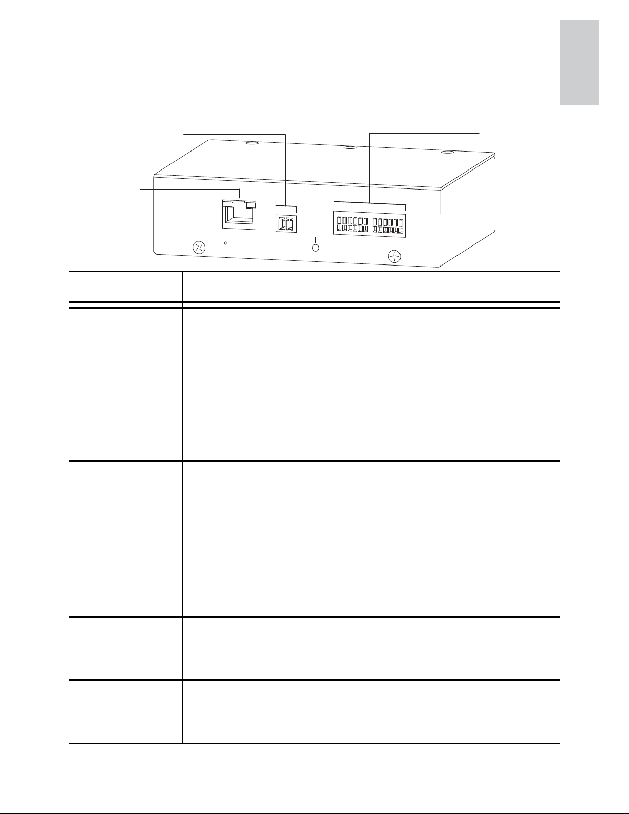
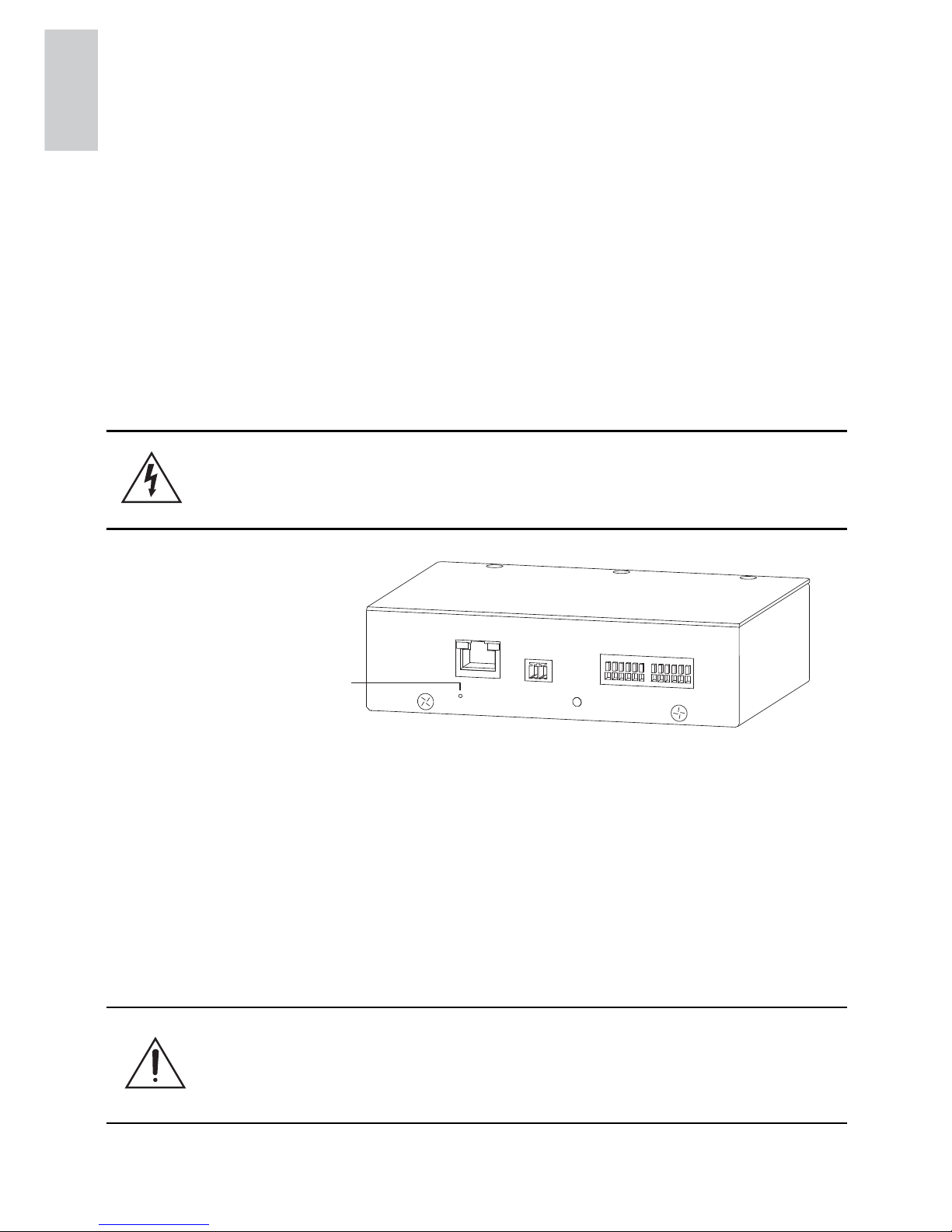
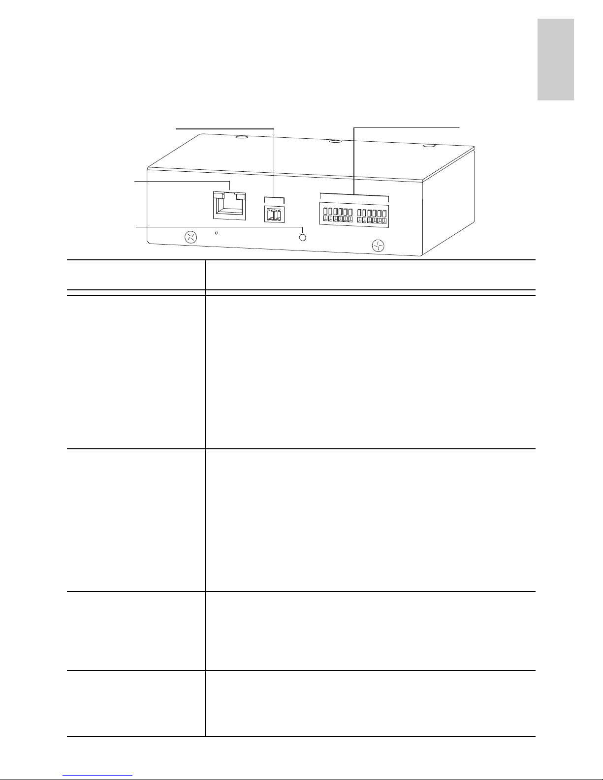
Rear View
Feature Description
Connection
Status LED
Provides information about the network connection.
See the section about connecting to the network
video recorder for more information.
The Connection Status LED can be turned off for
operating in covert installations. See the Avigilon
Control Center Client User Guide for more
information.
Ethernet Port Accepts an Ethernet connection to a network. Server
communication and image data transmission occurs
over this connection. Also receives power when it is
connected to a network that provides Power over
Ethernet.
The Ethernet Port has two status lights indicating
link (left) and activity (right).
Power
Connector
Block
Accepts a terminal block with either AC or DC power
connection. DC input can be either polarity. Only
required when Power over Ethernet is not available.
I/O Terminals Provides connections to external input/output
devices. See the section about connecting external
devices for more information.
I/O
Terminals
Power Connector
Block
Ethernet
Port
Connection
Status LED
2
English
English
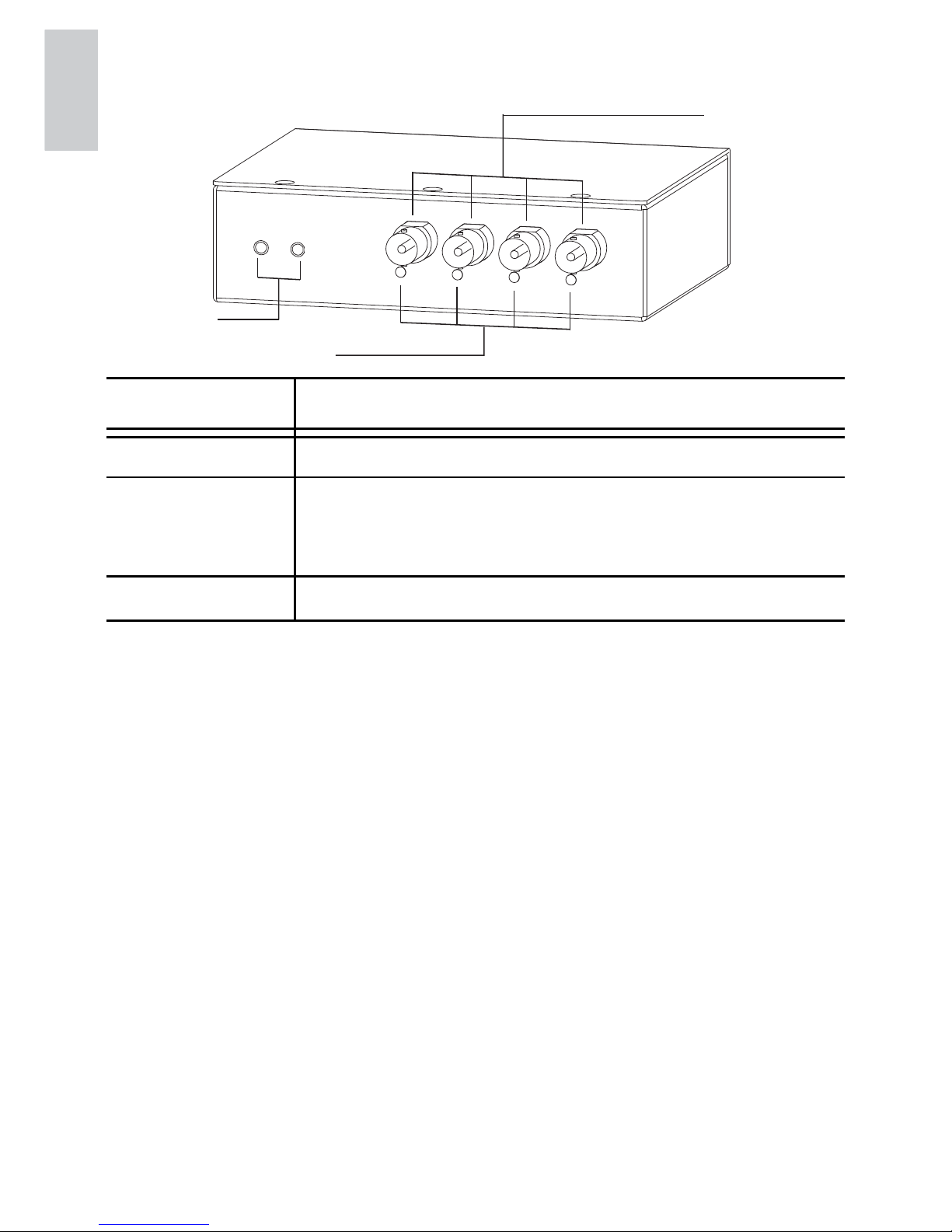
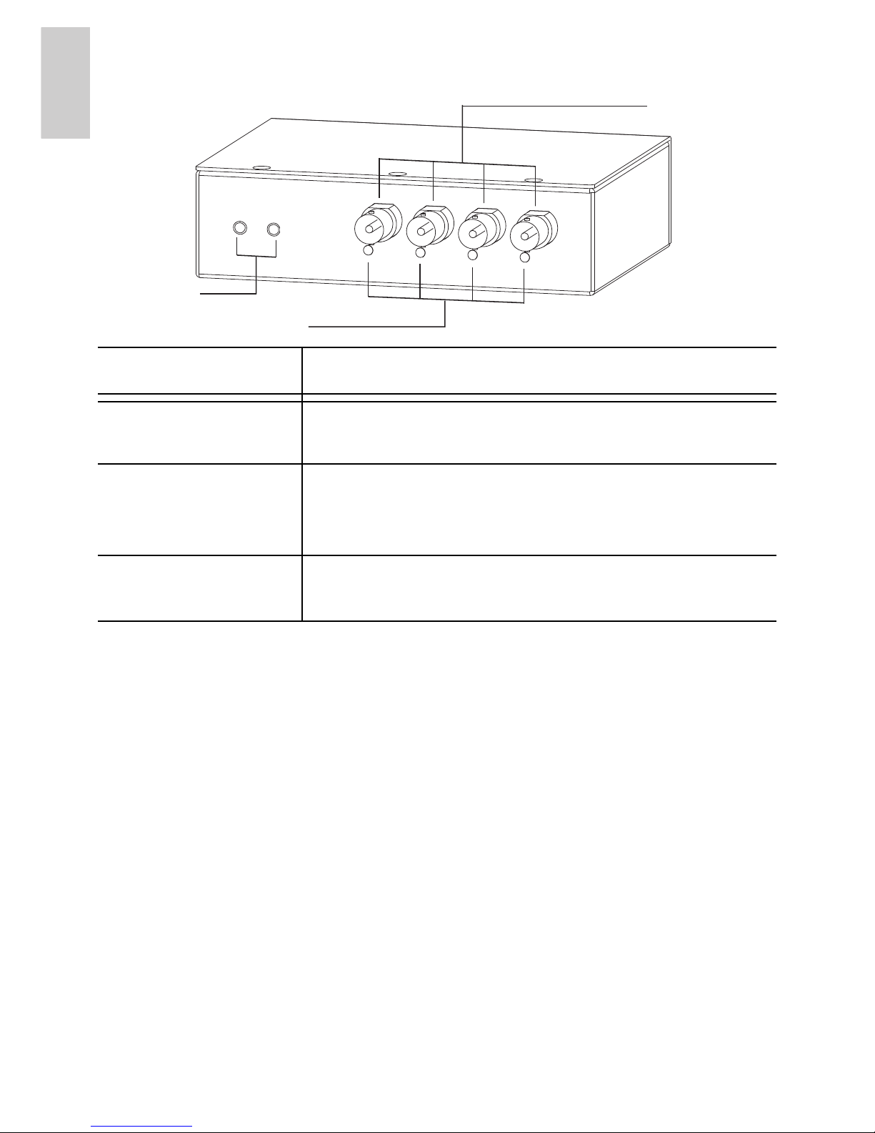
Front View
Feature Description
Video Inputs 4 BNC inputs for connecting analog video devices.
Video Input
Status LEDs
Provides information about the status of the analog
video signal. The LED turns on when a video
signal has been detected.
Audio Inputs 2 x 3.5 mm inputs for connecting microphones.
Audio
Inputs
Video Input
Status LEDs
Video Inputs

3
English
English
Installation
Required Tools and Materials
• Small slotted screwdriver with 5/64” or 2 mm blade width
— for connecting power when not using Power over
Ethernet.
Package Contents
Ensure the package contains the following:
• Avigilon Analog Video Encoder
• Terminal Block
Installation Steps
Complete the following procedures to install the encoder.
1. Mounting the Encoder on page 4
2. Connecting Power on page 5
3. Connecting Analog Cameras to the Encoder on page 6
4. Connecting to the Network Video Recorder on page 6
4
English
English
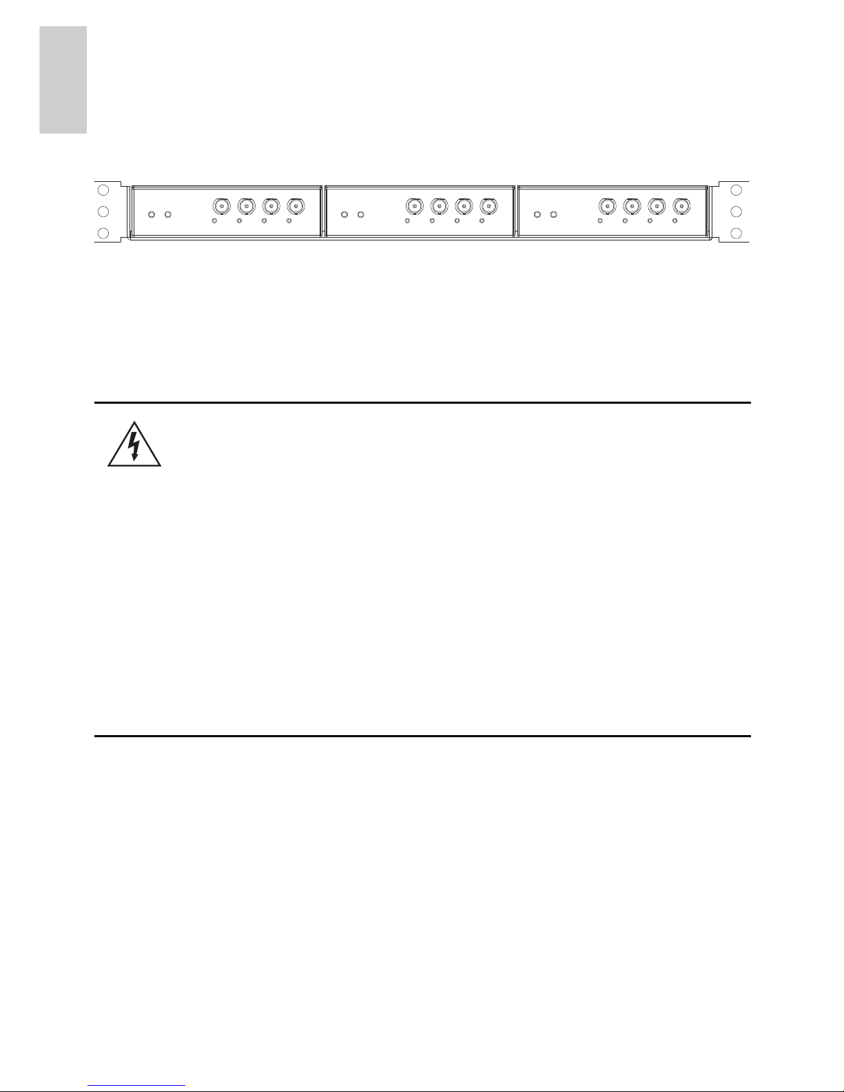
Mounting the Encoder
The encoder can be mounted in a 19” rack by attaching it to the ENCBRK1U encoder bracket that can be purchased separately. The
bracket takes up only 1U of rack space and can hold 3 encoders.
Figure: ENC-BRK1U rack mountable bracket with 3 encoders.
The encoder can be attached to the bracket by lining up the four holes
on the bottom of the encoder with the hole pattern on the bracket and
screwing them together with the screws provided with the bracket.
Warning —
• If installed in a closed or multi-unit rack
assembly, the operating ambient temperature of
the rack environment may be greater than room
ambient. Ensure that the ambient temperature
inside the rack does not exceed the maximum
operating temperature of the encoder.
• Ensure that sufficient airflow is provided in the
rack environment such that safe operation of the
equipment is not compromised.
• Mounting of the equipment in the rack should be
such that a hazardous condition is not created
due to uneven mechanical loading.

5
English
English
Connecting Power
NOTE: Do not perform this procedure if Power over Ethernet (POE) is
used.
If PoE is not available, the encoder needs to be powered through the
removable power connector block. Refer to the diagrams in this guide
for the location of the power connector block.
The device can be powered from 12 VDC or 24 VAC. The power
consumption information is listed in the product specifications.
To connect power to the power connector block, complete the
following steps:
1. Remove the power connector block from the device.
2. Remove the insulation from ¼” (6 mm) of the power wires.
Do not nick or damage the wires.
3. Insert the two power wires into the two terminals on the
power connector block. The connection can be made with
either polarity.
Use a small slotted (5/64” or 2 mm blade width)
screwdriver to loosen and tighten the terminals.
4. Attach the power connector block back into the receptacle
on the device.
Warning —
• Only power the encoder using a Class 2 power
supply that is UL Listed, CSA approved, or bears the
CE mark. Never connect the encoder directly to
mains power.
• In installations where multiple encoders are powered
from the same power supply, ensure that the power
supply, wiring, and all connections are rated for the
total power required by all the encoders on the circuit.

6
English
English
When you select the wire used to provide power, be sure to select a
gauge that is heavy enough for the wiring distance. Refer to the
following table for the maximum wire length for different wire gauges.
Connecting Analog Cameras to the Encoder
Connect analog video cameras to the encoder using the coax/BNC
connector video inputs on the front of the encoder. The encoder
supports 4 video inputs and is initially configured for a composite
video input with 75 ohm termination. The video standard (NTSC/PAL)
is automatically detected. The video input status LEDs will turn on if
the encoder locks to the video signal. If the video source is connected
in parallel with other equipment, the input termination should be
turned off, this can be done through the Avigilon Control Center
software.
Connecting to the Network Video Recorder
Important: To avoid networking problems, only use network switches
recommended by Avigilon.
Connect the encoder to the same network as the server running the
Avigilon Control Center software. An IP address is automatically
assigned to the device, and will be detected by the software. For more
Table:Maximum power wire run length for different wire gauges
Wire Gauge Maximum Run Length (ft [m])
AWG
mm
2
24 VAC 12 VDC
24 0.2 131[40] 29[8]
22 0.33 214[65] 47[14]
20 0.5 342[104] 76[23]
18 0.82 545[166] 121[36]
16 1.3 857[261] 190[58]

7
English
English
information on how to configure the connection, see the software user
guide.
The connection status LEDs show the progress in connecting to the
server and are described in the following table.
IP Address Selection
Once connected to a network, the encoder will attempt to locate and
obtain an IP address from a DHCP server. If this fails, an IP address
will be selected using Zeroconf (APIPA).
If the IP address is set using Zeroconf, the IP address will be in the
169.254.* subnet. A static IP address can be set from the Avigilon
Control Center software, consult the software user guide for details.
Table:Connection Status LED States
Connection
State
Connection
Status LED
Description
No Link Off Not physically connected to any
network device
Obtaining IP
Address
One short
flash every
second
Attempting to obtain an IP address
Connecting to
a server
Two short
flashes every
second
An IP address has been obtained
and is attempting to connect to the
server
Upgrading
Firmware
Two short
flashes and
one long flash
every second
Updating the firmware
Connected On Connected to the server
8
English
English
Advanced Features
Upgrading the Firmware
The firmware can be field-upgraded through the Avigilon Control
Center software. Consult the software user guide for details on how
firmware upgrades are performed.
It is possible for the firmware to become corrupted during an upgrade
— for example, if power is lost during the upgrade process. If this
occurs, the encoder can be reverted to run from bootstrap firmware.
Once reverted, it can be upgraded as usual.
Figure: Firmware revert microswitch location on the rear of the
encoder
1. Disconnect power from the encoder.
2. Using a straightened paperclip or similar tool, gently press
and hold the firmware revert microswitch.
3. While continuing to hold the microswitch, power the
device. Release the microswitch after three seconds.
Warning — Only revert to bootstrap firmware if the device is
unable to start up due to corrupted firmware.
Caution — Do not apply excessive force. Inserting the tool
too far will damage the device.
Firmware Revert Button
9
English
English
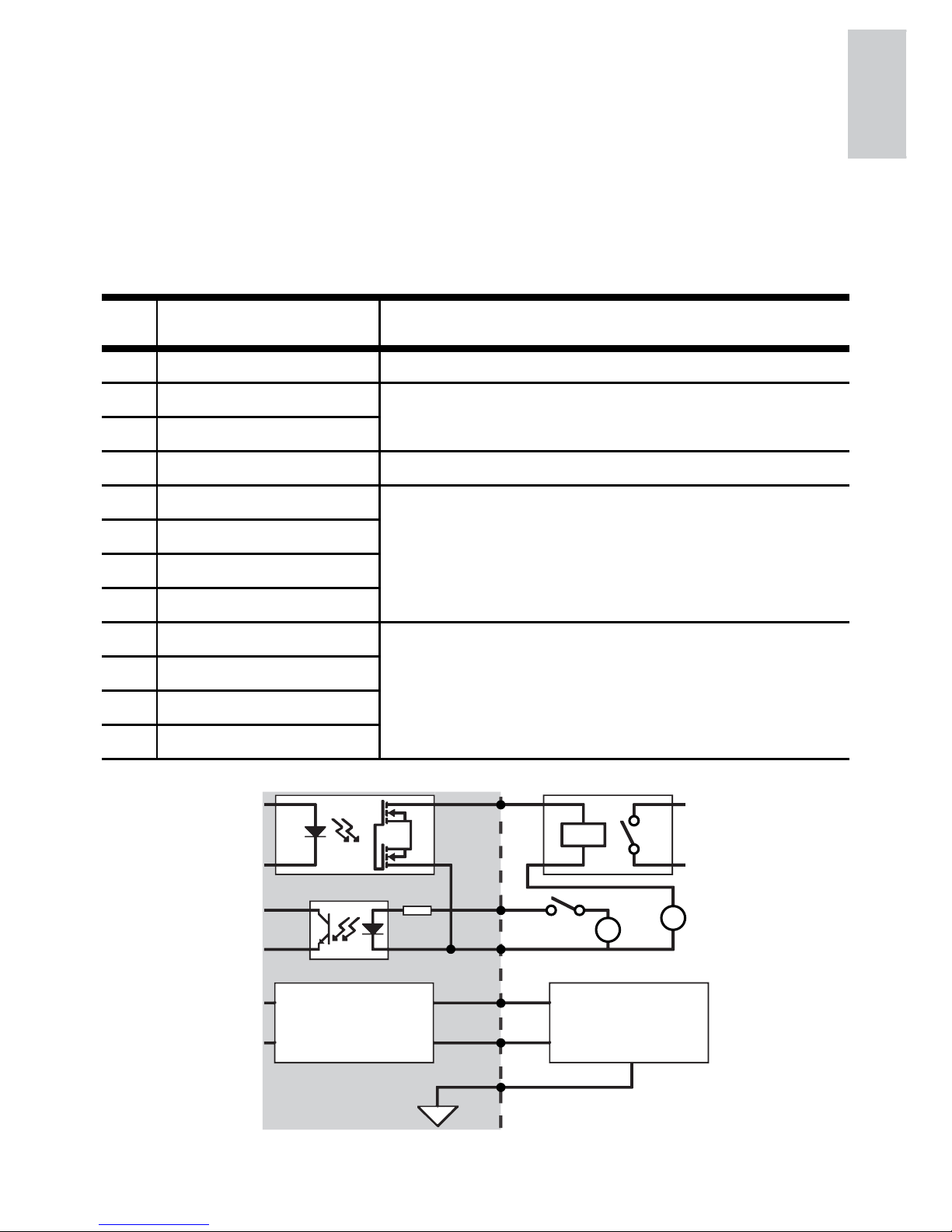
Connecting to External Devices
External devices are connected through the I/O terminal. The pinout
for the I/O terminal is shown in the following table and diagram.
Consult the software user guide for details on how to configure the
external devices.
Figure: External I/O terminal schematics and example applications.
Table:External I/O Terminals
Pin Function Description
1 GND Ground for RS-485 interface.
2 RS-485 RX/TX+ Half-duplex RS-485 interface for controlling
external equipment.
3 RS-485 RX/TX-
4 I/O Common Shared pin for Input and Output.
5 Input 4(+) The input uses a photocoupler and is electrically
isolated from the internal circuitry. The input
voltage should not exceed 12 V.
6 Input 3(+)
7 Input 2(+)
8 Input 1(+)
9 Output 4 The output uses a photocoupler and is electrically
isolated from the internal circuitry. The output
terminal connections can be made with either
polarity. The output can drive a maximum load of
50 V and 120 mA.
10 Output 3
11 Output 2
12 Output 1
RS-485
1
2
3
4
5-8
9-12
24V
3V
+
+
-
-
External Device
Encoder
Relay
Switch

10
English
English
Connecting Microphones
The encoder can be connected to two external microphone through
the audio connectors. The audio connectors are 3.5 mm (1/8”) inputs
for a mono microphone, or a line-in mono signal. The left channel of
the stereo signal is used. Consult the software user guide for details
on how configure the audio input.

11
English
English
Specifications
Network
Network 100Base-TX
Cabling Type CAT5
Connector RJ-45
Security SSL
Protocol UDP, TCP, SOAP, DHCP, Zeroconf
Mechanical
Dimensions LxWxH 140 mm x 122 mm x 44 mm
5.5” x 4.8” x 1.7”
Weight 0.62 kg (1.4 lbs)
Electrical
Power Source VDC: 12-24 V
VAC: 24 V
PoE: IEEE802.3af Class 3 compliant
Power Consumption 8 W
Power Connector 2-pin terminal block
Environmental
Operating
Temperature
-10 °C to +50 °C (14 °F to 122 °F)
Storage Temperature -10 °C to +70 °C (14 °F to 158 °F)
Humidity 20 - 80% Relative humidity (non-condensing)
Certifications
UL 60950 CSA60950
EN 60950-1 CE
ROHS WEEE
Electromagnetic
Emissions
FCC Part 15 Subpart B Class A
IC ICES-003 Class A EN 55022 Class A
EN 61000-6-3 EN 61000-3-2
EN 61000-3-3
Electromagnetic
Immunity
EN 50130-4
EN 61000-4-2 EN 61000-4-5
EN 61000-4-3 EN 61000-4-6
EN 61000-4-4 EN 61000-4-11

12
English
Limited Warranty & Technical Support
Avigilon warrants to the original consumer purchaser, that this product
will be free of defects in material and workmanship for a period of 3
years from date of purchase. The manufacturer’s liability hereunder is
limited to replacement of the product, repair of the product or
replacement of the product with repaired product at the discretion of
the manufacturer. This warranty is void if the product has been
damaged by accident, unreasonable use, neglect, tampering or other
causes not arising from defects in material or workmanship. This
warranty extends to the original consumer purchaser of the product
only.
AVIGILON DISCLAIMS ALL OTHER WARRANTIES EXPRESSED
OR IMPLIED INCLUDING, WITHOUT LIMITATION, ANY IMPLIED
WARRANTIES OF MERCHANTABILITY OR FITNESS FOR A
PARTICULAR PURPOSE, EXCEPT TO THE EXTENT THAT ANY
WARRANTIES IMPLIED BY LAW CANNOT BE VALIDLY WAIVED.
No oral or written information, advice or representation provided by
Avigilon, its distributors, dealers, agents or employees shall create
another warranty or modify this warranty. This warranty states
Avigilon’s entire liability and your exclusive remedy against Avigilon for
any failure of this product to operate properly.
In no event shall Avigilon be liable for any indirect, incidental, special,
consequential, exemplary, or punitive damages whatsoever (including
but not limited to, damages for loss of profits or confidential or other
information, for business interruption, for personal injury, for loss of
privacy, for failure to meet any duty including of good faith or of
reasonable care, for negligence, and for any other pecuniary or other
loss whatsoever) arising from the use of or inability to use the product,
even if advised of the possibility of such damages. Since some
jurisdictions do not allow the above limitation of liability, such limitation
may not apply to you.
This Limited Warranty gives you specific legal rights and you may also
have other rights which vary from jurisdiction to jurisdiction.
Warranty service and technical support can be obtained by contacting
Avigilon Technical Support by phone at 1.888.281.5182 or via email at
support@avigilon.com.

Guide d'installation
Modèle d'encodeur analogique vidéo Avigilon :
ENC-4PORT-2AI
920-0013A-Rev2
i
Françai
s
Français
Informations de sécurité
importantes
Ce manuel fournit des informations d'installation et d'exploitation, ainsi
que des précautions d'utilisation pour l'encodeur. Une installation
incorrecte peut entraîner une défaillance imprévue. Avant d'installer
cet équipement, lisez attentivement ce manuel. Veuillez remettre ce
manuel au propriétaire de l'équipement pour une utilisation ultérieure.
• N'utilisez pas l'équipement à proximité de l'eau ; ne l'exposez
pas à des éclaboussures ou des fuites. Ne placez aucun
objet rempli de liquide au-dessus de l'équipement.
• N'exposez pas l'équipement à la pluie ou aux moisissures.
• Pour une utilisation en intérieur uniquement.
Si l'équipement est utilisé en extérieur, un adaptateur ou
un boîtier de fixation en extérieur approuvé est obligatoire.
Consultez Avigilon pour plus d'informations.
• L'installation doit être effectuée par un personnel qualifié
uniquement et doit être en conformité avec tous les codes
locaux.
Le symbole d'avertissement indique la présence de tensions
dangereuses, à l'intérieur et à l'extérieur du boîtier du produit,
susceptibles de générer un risque de choc électrique, de
blessure grave, voire de décès, si des précautions appropriées
ne sont pas prises.
Le symbole Attention alerte l'utilisateur sur la présence de
dangers susceptibles d'infliger aux personnels des blessures
mineures à modérées, d'endommager des biens ou le produit
lui-même si des précautions appropriées ne sont pas prises.
Avertissement — Le non-respect des instructions
suivantes est susceptible d'entraîner des blessures graves
voire le décès.
ii
Françai
s
Français
• Utilisez uniquement des méthodes et des matériaux
capables de supporter quatre fois la charge maximale
spécifiée.
• L'encodeur doit être alimenté uniquement par une
alimentation de Classe 2 ou PoE, répertoriée UL,
approuvée CSA ou portant l'étiquetage CE.
• Toute alimentation externe connectée à ce produit ne peut
être connectée qu'à un autre produit Avigilon de la même
gamme de modèles. Les connexions à des alimentations
externes doivent être correctement isolées.
• Pour quelque raison que ce soit, ne connectez pas
l'équipement directement au secteur.
• N'effectuez aucune installation à proximité de sources de chaleur
telles que radiateurs, bouches de chaleur ou poêles.
• Ne soumettez pas les câbles à des tensions, des charges ou
des pincements excessifs.
• N'ouvrez pas l'équipement, ne le démontez pas. Il ne contient
aucune pièce sur laquelle l'utilisateur peut intervenir.
• Pour toute intervention, contactez un personnel qualifié.
Une intervention peut se révéler nécessaire lorsque
l'équipement est endommagé (par exemple, par le
renversement d'un liquide ou la chute d'un objet), lorsqu'il a été
exposé à la pluie ou à l'humidité (présence de moisissure),
lorsqu'il ne fonctionne pas normalement ou lorsqu'il a chuté.
• N'utilisez pas de détergents puissants ou abrasifs lorsque vous
nettoyez le corps de l'équipement.
• Utilisez uniquement les accessoires recommandés par Avigilon.
• L'utilisation de commandes, de réglages ou de procédures autres
que ceux spécifiés dans le présent document peut entraîner une
exposition à des radiations dangereuses.
Attention — Le non-respect des instructions suivantes est
susceptible d'entraîner des blessures et d'endommager l'encodeur.

iii
Françai
s
Français
Notices relatives à la réglementation
Cet équipement est conforme à section 15 des règles FCC. Son
exploitation est sujettes aux deux conditions suivantes : (1) Cet
équipement ne risque pas de générer d'interférences nuisibles et (2)
cet équipement doit accepter toute interférence reçue, y compris
celles susceptibles d'induire un fonctionnement indésirable.
Cet équipement numérique de Classe A est conforme à la norme
canadienne ICES-003.
Notice FCC
Cet équipement a été testé et déclaré conforme aux limitations
relatives à un appareil numérique de classe A, en vertu de la Section
15 des règles de la FCC. Ces limitations visent à assurer une
protection raisonnable contre les interférences dans le cadre d'une
exploitation de l'équipement dans un environnement commercial. Cet
équipement génère, utilise et irradie de l'énergie radiofréquence, et
risque, s'il n'est pas installé et utilisé conformément à son manuel
d'instruction, de provoquer des interférences nuisibles pour les
communications radiophoniques. L'exploitation de cet équipement
dans une zone résidentielle est susceptible de générer des
interférences nuisibles, auquel cas l'utilisateur sera tenu de remédier à
ces interférences à ses propres dépends.
Tout changement ou modification apporté à cet équipement non
expressément approuvé par Avigilon Corporation ou des tiers
autorisés par Avigilon Corporation pourrait annuler l'autorisation
accordée à l'utilisateur d'utiliser cet équipement.
Informations sur la mise au rebut et le
recyclage
Lorsque ce produit aura atteint la fin de sa vie utile, veuillez le mettre
au rebut conformément aux directives et à la législation locales sur
l'environnement.

iv
Françai
s
Français
Union européenne :
Ce symbole signifie que, conformément aux lois et aux
réglementations locales, votre produit doit être mis au rebut
hors déchets ménagers. Lorsque ce produit aura atteint la fin
de sa vie utile, portez-le à un point de collecte désigné par
les autorités locales. Certains points de collecte acceptent
gratuitement les produits. La collecte et le recyclage séparés
de votre produit au moment de la mise au rebut contribuent à
conserver les ressources naturelles et garantissent que le
produit est recyclé de sorte à protéger la santé humaine et
l'environnement.

v
Françai
s
Français
Autres notices
Notice sur la compilation et la publication
Ce manuel a été compilé et publié en couvrant les spécifications et
descriptions de produit les plus récentes. Le contenu de ce manuel et
les spécifications de ce produit sont sujets à modifications sans avis
préalable. Avigilon se réserve le droit d'apporter des modifications
sans avis préalable aux spécifications et informations présentées
dans le présent manuel. Avigilon ne saurait être tenu responsable de
tout dommage (notamment accessoire) causé par le fait de se fier aux
informations présentées, notamment mais sans s'y limiter, en termes
d'erreurs typographiques et d'autres erreurs liées à la publication.
Notice de propriété intellectuelle
Aucun licence n'est accordée par implication ou autre action dans le
cadre de toute conception industrielle, de droits de conception
industriels, de brevet et droits de brevet, ou de droits de reproduction
(copyrights) d'Avigilon Corporation ou de ses concédants de licence.
Les marques commerciales et les marques déposées sont la propriété
de leurs détenteurs respectifs.
Certaines parties du logiciel de ce produit sont cédées sous licence
dans le cadre de la licence eCos. La distribution de licences eCos
implique que le code source eCos soit mis à la disposition des clients
d'Avigilon. La licence eCos et le code source eCos sont mis à la
disposition du public sur le site Web http://www.avigilon.com/
ecoslicense. Avigilon se réserve tous les droits sur toutes les logiciels
non couverts par la licence eCos. Ceux-ci comprennent tous les
parties du logiciel non distribuées à Avigilon en tant que composants
du système d'exploitation eCos.

English
Français
Tables des matières
Présentation générale . . . . . . . . . . . . . . . . . . . 1
Vue arrière . . . . . . . . . . . . . . . . . . . . . . . . . . . . . . . 1
Vue avant . . . . . . . . . . . . . . . . . . . . . . . . . . . . . . . . 2
Installation . . . . . . . . . . . . . . . . . . . . . . . . . . . . . 3
Outils et matériel requis . . . . . . . . . . . . . . . . . . . . . 3
Contenu du conditionnement . . . . . . . . . . . . . . . . . 3
Étapes d'installation . . . . . . . . . . . . . . . . . . . . . . . . 3
Fixation de l'encodeur . . . . . . . . . . . . . . . . . 4
Raccordement de l'alimentation . . . . . . . . . 4
Raccordement de caméras
analogiques à l'encodeur . . . . . . . . . . . . . . . 6
Raccordement à l'enregistreur
vidéo en réseau (NVR) . . . . . . . . . . . . . . . . 6
Sélection de l'adresse IP . . . . . . . . . . . . . . . 7
Caractéristiques avancées . . . . . . . . . . . . . . . 8
Mise à niveau du microcode . . . . . . . . . . . . . . . . . . 8
Connexion à des périphériques externes . . . . . . . . 9
Raccordement de microphones . . . . . . . . . . . . . . 10
Spécifications . . . . . . . . . . . . . . . . . . . . . . . . . 11
Garantie limitée et assistance technique . . . 12
1
Françai
s
Français
Présentation générale
Vue arrière
Caractéristique Description
LED d'état de
connexion
Fournit des informations sur la connexion réseau.
Consultez la section sur la connexion à
l'enregistreur vidéo en réseau, ou NVR (Network
Video Recorder), pour plus d'informations.
La diode (LED) d'état de connexion peut être
éteinte pour un fonctionnement dans des
installations discrètes. Reportez-vous au Guide de
l'utilisateur d'Avigilon Control Center Client pour
plus d'informations.
Port Ethernet Accepte une connexion Ethernet à un réseau. La
transmission des données d'images et de
communication avec le serveur s'effectue par cette
connexion. Reçoit également l'alimentation en cas
de connexion à un réseau à fonctionnalité PoE
(Power over Ethernet).
Le port Ethernet dispose : de deux diodes d'état
indiquant la liaison (gauche) et l'activité (droite).
Bloc connecteur
d'alimentation
Accepte un bloc de borniers avec une connexion
d'alimentation en CC ou CA. L'entrée en CC ne
tient pas compte de la polarité. Requis uniquement
lorsque la technologie PoE (Power over Ethernet)
n'est pas disponible.
Borniers E/S Fournit des connexions à des périphériques
d'entrée/de sortie externes. Reportez-vous à la
section relative à la connexion de périphériques
externes pour plus d'informations.
Borniers
E/S
Bloc connecteur
d'alimentation
Port
Ethernet
LED d'état
de connexion
2
Françai
s
Français
Vue avant
Caractéristique Description
Entrées vidéo 4 entrées BNC pour la connexion
d'équipements vidéo analogiques
LED d'état d'entrée
vidéo
Fournit des informations sur l'état du signal
vidéo analogique. La diode s'allume lorsqu'un
signal vidéo est détecté.
Entrées Audio Deux connexions de 3,5 mm pour la connexion
de microphones.
Entrées
Audio
LED d'état d'entrée vidéo
Entrées vidéo

3
Françai
s
Français
Installation
Outils et matériel requis
• Petit tournevis à lame plate de 2 mm (ou 5/64 pouce) de
large ; pour le raccordement de l'alimentation si l'appareil
ne dispose pas de connexion PoE (Power over Ethernet).
Contenu du conditionnement
Assurez-vous que le conditionnement contient les éléments suivants :
• Encodeur analogique vidéo Avigilon
• Bloc de borniers
Étapes d'installation
Effectuez les procédures suivantes pour installer l'encodeur.
1. Fixation de l'encodeur à la page 4
2. Raccordement de l'alimentation à la page 4
3. Raccordement de caméras analogiques à l'encodeur à la
page 6
4. Raccordement à l'enregistreur vidéo en réseau (NVR) à la
page 6

4
Françai
s
Français
Fixation de l'encodeur
L'encodeur peut être installé sur un châssis 19 pouces. Pour ce faire,
fixez le au support d'encodeur ENC-BRK1U vendu séparément. Le
support n'occupe qu'un espace de châssis 1U et peut accueillir trois
encodeurs.
Figure : Support pour montage en châssis ENC-BRK1U avec 3
encodeurs
Pour fixer l'encodeur au support, alignez les quatre trous du dessous
de l'appareil sur les perçages du support, puis vissez l'ensemble au
moyen des vis fournies avec le support.
Raccordement de l'alimentation
REMARQUE : N'effectuez pas cette procédure si vous utilisez la
technologie POE (Power over Ethernet).
Avertissement —
• Si l'appareil est installé dans un assemblage clôt
ou comportant un châssis à plusieurs unités, la
température ambiante d'exploitation de cet
assemblage peut être plus élevée que celle de la
pièce. Assurez-vous que la température
ambiante interne du châssis ne dépasse pas la
température maximale d'exploitation de
l'encodeur.
• Assurez-vous qu'un flux d'air suffisant circule
dans l'environnement du châssis pour garantir
qu'un fonctionnement sûr de l'équipement n'est
pas compromis.
• L'installation de l'équipement sur le châssis doit
s'effectuer de sorte à n'induire aucun danger lié à
une charge mécanique inégale.
 Loading...