

Page 1

Avigilon Control Center Client
User Guide
Version: 4.12 Standard
PDF-CLIENT-S-F-Rev2
Page 2

Copyright © 2013 Avigilon. All rights reserved.
The information presented is subject to change without notice.
No copying, distribution, publication, modification, or incorporati on of this document , in whole or part, is permitt ed without the
express written permission of Avigilon. In the event of any permitted copying, distribution, publication, modification, or incorporation
of this document, no changes in or deletion of author attribution, trademark legend, or copyright notice shall be made. No part of this
document may be reproduced, stored in a retrieval system, published, used for commercial exploitation, or transmitted, in any form
by any means, electronic, mechanical, photocopying, recording, or otherwise, without the express written permissi on of Avigilon.
Avigilon
Tel +1.604.629.5182
Fax +1.604.629.5183
http://www.avigilon.com
Revised 2013-03-12
Page 3

Table of Contents
Introduction .............................................................................................................................. 1
What is the Avigilon Control Center Client? .............................................................................................. 1
System Requirements ............................................................................................................................... 1
For More Information ................................................................................................................................. 2
Avigilon Training Center ........................................................................................................................ 2
Support .................................................................................................................................................. 2
Upgrades ............................................................................................................................................... 2
Feedback ............................................................................................................................................... 3
Getting Started ......................................................................................................................... 4
Starting and Shutting Down the Avigilon Control Center Client ................................................................ 4
Starting the Client Software .................................................................................................................. 4
Shutting Down the Client Software ....................................................................................................... 4
Discovering Servers .................................................................................................................................. 5
Logging Into and Out of Servers ............................................................................................................... 6
Logging In .............................................................................................................................................. 7
Logging Out ........................................................................................................................................... 8
Navigating the Application......................................................................................................................... 8
Adding and Removing Cameras in a View ............................................................................................. 10
Adding a Camera to a View ................................................................................................................ 10
Removing a Camera From a View ...................................................................................................... 10
Viewing Live and Recorded Video .......................................................................................................... 11
Setup ........................................................................................................................................12
Managing Server Connections ................................................................................................................ 12
Discovering Servers ............................................................................................................................ 12
Editing and Deleting a Server Connection .......................................................................................... 14
Managing User Connections to a Server ............................................................................................ 15
Connect/Disconnect Cameras ................................................................................................................ 16
iii
Page 4

Avigilon Control Center Standard Client User Guide
Discovering a Camera ......................................................................................................................... 16
Connecting a Camera to a Server....................................................................................................... 17
Editing the Camera Connection to the Server .................................................................................... 19
Disconnecting a Camera from a Server .............................................................................................. 19
Upgrading Camera Firmware .............................................................................................................. 19
Server Setup ........................................................................................................................................... 20
Accessing the Server Setup ................................................................................................................ 20
General ................................................................................................................................................ 21
Recording Schedule ............................................................................................................................ 22
Recording and Bandwidth ................................................................................................................... 24
Users and Groups ............................................................................................................................... 26
POS Transactions ............................................................................................................................... 35
Email Notification ................................................................................................................................ 42
System Log ......................................................................................................................................... 46
Scheduling Server Events ................................................................................................................... 47
Camera Setup ......................................................................................................................................... 48
Accessing the Camera Setup.............................................................................................................. 48
General ................................................................................................................................................ 49
Network ............................................................................................................................................... 52
Image and Display .............................................................................................................................. 54
Compression and Image Rate ............................................................................................................ 57
Image Dimensions .............................................................................................................................. 59
Motion Detection ................................................................................................................................. 60
Privacy Zones...................................................................................................................................... 62
Manual Recording ............................................................................................................................... 64
Digital Inputs and Outputs ................................................................................................................... 65
Microphone
.......................................................................................................................................... 68
Speaker ............................................................................................................................................... 69
Client Setup ............................................................................................................................................. 71
Accessing the Client Setup ................................................................................................................. 71
General ................................................................................................................................................ 72
Joystick ................................................................................................................................................ 73
Exporting Settings ............................................................................................................................... 75
Import Settings .................................................................................................................................... 76
Microphone .......................................................................................................................................... 77
iv
Page 5

Table of Contents
Views .......................................................................................................................................79
What are Views? ..................................................................................................................................... 79
Adding and Removing a View ................................................................................................................. 79
Adding a New View to the Application Window .................................................................................. 79
Adding a V iew to a New Window ........................................................................................................ 79
Closing a View from the Application Window ...................................................................................... 80
Closing a Window ............................................................................................................................... 80
View Layouts ........................................................................................................................................... 80
Selecting a Layout for a View .............................................................................................................. 80
Editing a View Layout .......................................................................................................................... 81
Making a View Full Screen...................................................................................................................... 83
Ending Full Screen .............................................................................................................................. 84
Cycling Through Views ........................................................................................................................... 84
Saving a View ......................................................................................................................................... 84
Saving a View...................................................................................................................................... 84
Opening a Saved View ........................................................................................................................ 85
Renaming a Saved View ..................................................................................................................... 85
Deleting a Saved View ........................................................................................................................ 85
Video ........................................................................................................................................86
Monitoring Live Video .............................................................................................................................. 86
Adding and Removing Cameras in a View ......................................................................................... 86
Displaying Live Video .......................................................................................................................... 87
Using Instant Replay ........................................................................................................................... 87
Zooming and Panning a Video ............................................................................................................ 87
Monitoring PTZ Cameras .................................................................................................................... 88
Listening to Audio in a View ................................................................................................................ 94
Broadcasting Audio in a View ............................................................................................................. 95
Triggering Manual Recording .............................................................................................................. 95
Triggering Digital Output ..................................................................................................................... 96
Monitoring POS Transactions ............................................................................................................. 96
Monitoring Recorded Video..................................................................................................................... 97
Adding and Removing Cameras in a View ......................................................................................... 97
Displaying Recorded Video ................................................................................................................. 98
Zooming and Panning a Video ............................................................................................................ 98
Listening to Audio in a View ................................................................................................................ 99
v
Page 6

Avigilon Control Center Standard Client User Guide
Playing Back Recorded Video ........................................................................................................... 100
Bookmarking Recorded Video .......................................................................................................... 101
Reviewing POS Transactions ........................................................................................................... 104
Adjusting Video Display in Image Panels ............................................................................................. 105
Maximizing an Image Panel .............................................................................................................. 105
Displaying Video Overlays ................................................................................................................ 105
Changing the Image Panel Display Quality Settings ........................................................................ 106
Changing the Image Panel Display Adjustments Settings ................................................................ 107
Displaying Analog Video in Deinterlaced Mode ................................................................................ 108
Search .................................................................................................................................... 109
Performing an Event Search ................................................................................................................. 109
Viewing Event Search Results .......................................................................................................... 110
Performing a Bookmark Search ............................................................................................................ 111
Viewing Bookmark Search Res ults ................................................................................................... 112
Performing a Pixel Search .................................................................................................................... 113
Viewing Pixel Search Results ........................................................................................................... 114
Performing a Thumbnail Search ........................................................................................................... 114
Viewing Thumbnail Search Results .................................................................................................. 115
Performing a POS Transaction Search ................................................................................................. 116
Viewing POS Transaction Search Results ........................................................................................ 118
Export .................................................................................................................................... 119
Exporting a Snapshot of an Image ........................................................................................................ 119
Exporting Recorded Video and Images ................................................................................................ 122
Accessing the Export Tab ................................................................................................................. 122
Exporting Native Video ...................................................................................................................... 122
Exporting AVI Video .......................................................................................................................... 124
Exporting PNG, JPEG or TIFF Images ............................................................................................. 126
Exporting PDF and Print Images....................................................................................................... 128
Exporting WAV Audio ........................................................................................................................ 130
Appendix ............................................................................................................................... 132
Accessing the Web Client ..................................................................................................................... 132
Updating the Client Software ................................................................................................................ 133
Events and Descriptions ....................................................................................................................... 134
Group Permission Descriptions ......................................................................................................... 135
Email Descriptions ............................................................................................................................ 137
vi
Page 7

Table of Contents
Reporting Bugs ..................................................................................................................................... 138
Keyboard Commands ........................................................................................................................... 139
Image Panel & Camera Commands ................................................................................................. 139
View Commands ............................................................................................................................... 141
View Layout Commands ................................................................................................................... 142
Playback Commands ........................................................................................................................ 143
PTZ Commands (Digital and Mechanical) ........................................................................................ 144
Index ...................................................................................................................................... 147
vii
Page 8

Page 9

Minimum requirements
Recommended requirements
Introduction
What is the Avigilon Control Center Client?
The Avigilon Control Center Client software works with the Avigilon Control Center Server software to
give you access and control of your Avigilon High Definition Surveillance System.
The Client software allows you to view live and recorded video, and control user access to the Avigilon
Control Center. The Client software also gives you the ability to configure the server, cameras and other
external devices that are part of your surveillance system.
The Client software can run on the same computer as the Server software, or run on a remote computer
that connects with the Server software through a local area network (LAN) or a wireless area network
(WAN).
What you can do in the Client software depends on the Server software edition. There are three editions
of the Server software available: Core, Standard and Enterprise. Core contains all the essential software
features for monitoring live and recorded video. Standard gives you all the Core features plus access to
the point of sales feature, digital input and output, audio, and expanded search options. The Enterprise
edition gives you access to the full suite of Client software features, including alarms, rules, Site View,
Web Pages, Maps and system backup. Visit the Avigilon website for an overview of the features available
in each edition: http://avigilon.com/#/products/avigilon-control-center/editions/
A copy of the Client software can be downloaded from the Avigilon website, or installed with the Server
software.
System Requirements
Monitor
resolution
OS
1280 x 1024 1280 x 1024
Windows XP with Service Pack (SP) 2 or
later, Windows Vista, or Windows 7
Windows XP with Service Pack (SP)
2 or later, Windows Vista, or
1
Page 10

Avigilon Control Center Standard Client User Guide
Windows 7
CPU
System
RAM
Video card
Network
card
Hard disk
space
Intel Single Core 2.4 GHz processor Intel Dual Core 2.0 GHz processor
1 GB 2 GB
PCI Express, DirectX 9.0c compliant with 128
MB RAM (Intel GMA 900 or better, NVIDIA
6600 or better, ATI X1300 or better)
100 Mbps 1 Gbps
500 MB 500 MB
PCI Express, DirectX 10.0 com plia nt
with 256 MB RAM (NVIDIA GeForce
600 series or better)
For More Information
Visit Avigilon at http://www.avigilon.com/ for additional product documentation.
Avigilon Training Center
The Avigilon Training Center provides free online training videos that demonstrate how to set up and use
the Avigilon Surveillance System. Register online at the Avigilon Partner Portal site to
begin: http://avigilon.force.com/login
Support
For additional support information, visit http://avigilon.com/#/support-and-downloads/.
Regular Avigilon Customer Support Center hours of operation are from 6:00 a.m. to 6:00 p.m. Pacific
Standard Time (PST) and can be reached by calling the toll-free number: +1.888.281.5182.
E-mails can be sent to: support@avigilon.com
For emergency technical support 24 hours a day, 7 days a week, please call the Avigilon Emergency
Technical Support Hotline at +1.604.506.3117.
.
Upgrades
Software and firmware upgrades will be made available for download as they become available.
Check http://avigilon.com/#/support-and-downloads/
for available upgrades.
2
Page 11

Feedback
We value your feedback. Please send any comments on our products and services
to feedback@avigilon.com
Introduction
3
Page 12

Getting Started
Once the Avigilon Control Center Client software has been installed, you can start using the Avigilon High
Definition Surveillance System immediately. Refer to any of the following procedures to help you get
started.
To watch a video overview of the application, see the Introduction to Avigilon Control Center Client and
Viewing Live Video training video in the Avigilon Training Center.
Starting and Shutting Down the Avigilon Control Center Client
The Avigilon Control Center Client software can be started or shut down at anytime. The Avigilon Control
Center Server software is a Windows service and will continue to run in the background even when the
Client software is shut down.
Starting the Client Software
Perform one of the following:
From the Windows Start menu, select All Programs > Avigilon > Avigilon Control Center
Client > Avigilon Control Center Client.
Double-click the Avigilon Control Center Client shortcut icon on the desktop.
From the Avigilon Control Center Admin Tool, click Launch Control Center Client. See
the Avigilon Control Center Server User Guide for more information.
Log in to your server(s) when the Log In dialog box appears. See Logging_In
Shutting Down the Client Software
1. In the Avigilon Control Center Client software, select File > Exit.
for more information.
4
Page 13
Getting Started
2. In the confirmation dialog box, click Yes.
Discovering Servers
The Avigilon Control Center Client software must communicate with the Avigilon Control Center Server
software to access and configure your surveillance system. If the server is on the same network segment
(subnet) as your computer, the server is automatically discovered and appears in the System Explorer on
the left side of the application window.
If the server is on a different subnet, the server must be manually discovered. There is no limit to the
number of servers that can be discovered by the Client software.
1. Open the Find Server dialog box.
o In the Log In dialog box, click Find Server....
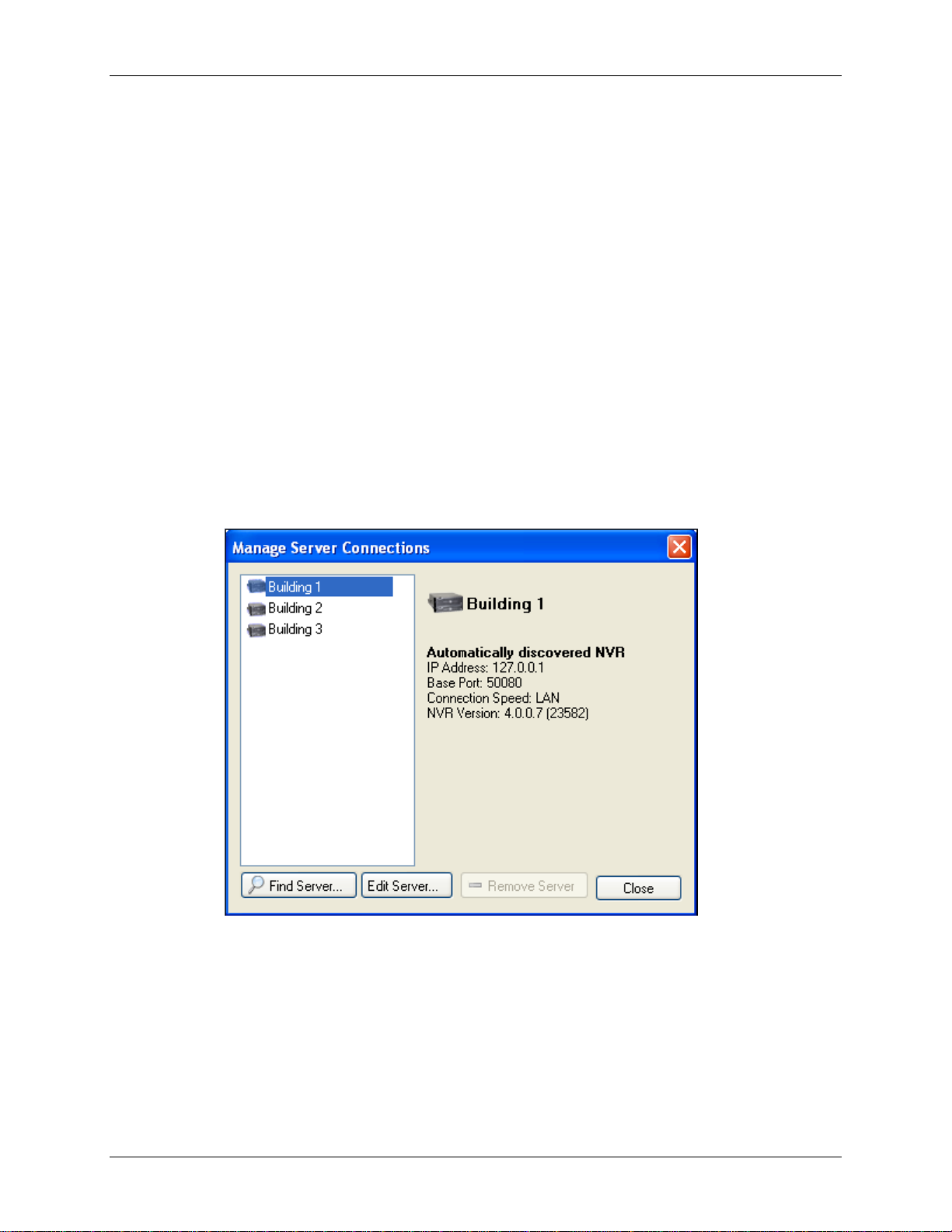
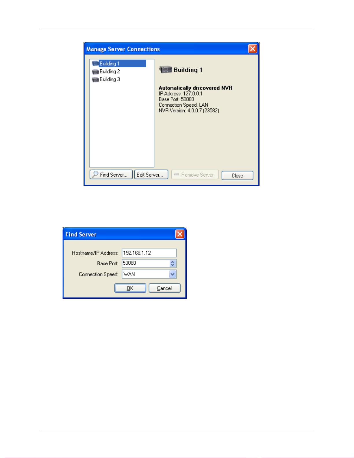
o In the application window, select File > Manage Server Connections. In the Manage
Servers dialog box, click Find Server...
Figure A. Manage Server Connections dialog box
2. In the Find Server dialog box, enter the Hostname/IP Address, the B a se Po rt , a nd
the Connection Speed of the server you want to discover.
5
Page 14

Avigilon Control Center Standard Client User Guide
Figure B. Find Server dialog box
The base port is 50080 by default. You can change the base port number in the Avigilon Control
Center Admin Tool. See the Avigilon Control Center Server User Guide for more information.
Tip:
Set the Connection Speed to WAN if you are on a low bandwidth network (for
example, internet or wireless network), and select LAN if you are on a high bandwidth
connection (for example, office or home network). This enables the Avigilon Control Center
to better manage your bandwidth and image rate.
3. Click OK.
If the server is found, the server will appear in the Manage Server Connections dialog box.
If the server is not found, check the following then try again:
The network settings are configured correctly.
The firewall is not blocking the application.
The Avigilon Control Center Server software is running on the server.
Logging Into and Out of Servers
To access your Avigilon High Definition Surveillance System through the Client software, you must log in
to the servers running the Avigilon Control Center Server software. Whenever the Client software detects
a server with the Server software installed, you are prompted to log in.
The default administrator access uses administrator as the username and no password. To maintain the
security of the administrator account, it is recommended that your system administrator immediately
create a password for this account after the first login. Your system administrator can then create user
accounts for other users.
If the Client software does not detect any servers, click Find Server.... See Discoveri ng Servers
information.
6
for more
Page 15
Getting Started
Logging In
Be aware that the number of servers you can log into at one time is determined by the type of server you
can access. Standard edition servers only allow you to be logged into three servers at the same time,
while Enterprise edition servers allow you to be logged into an unlimited number of servers.
Note: You cannot access Standard edition servers and Enterprise edition servers at the same time.
1. Open the Log In dialog box. The Log In dialog box automatically appears when a server is
detected by the Client software.
To manually access the Log In dialog box, perform one of the following:
o From the File menu, select Log In to log in to all available servers
o In the System Explorer, right-click a server and select Log In to log in to the selected
server.
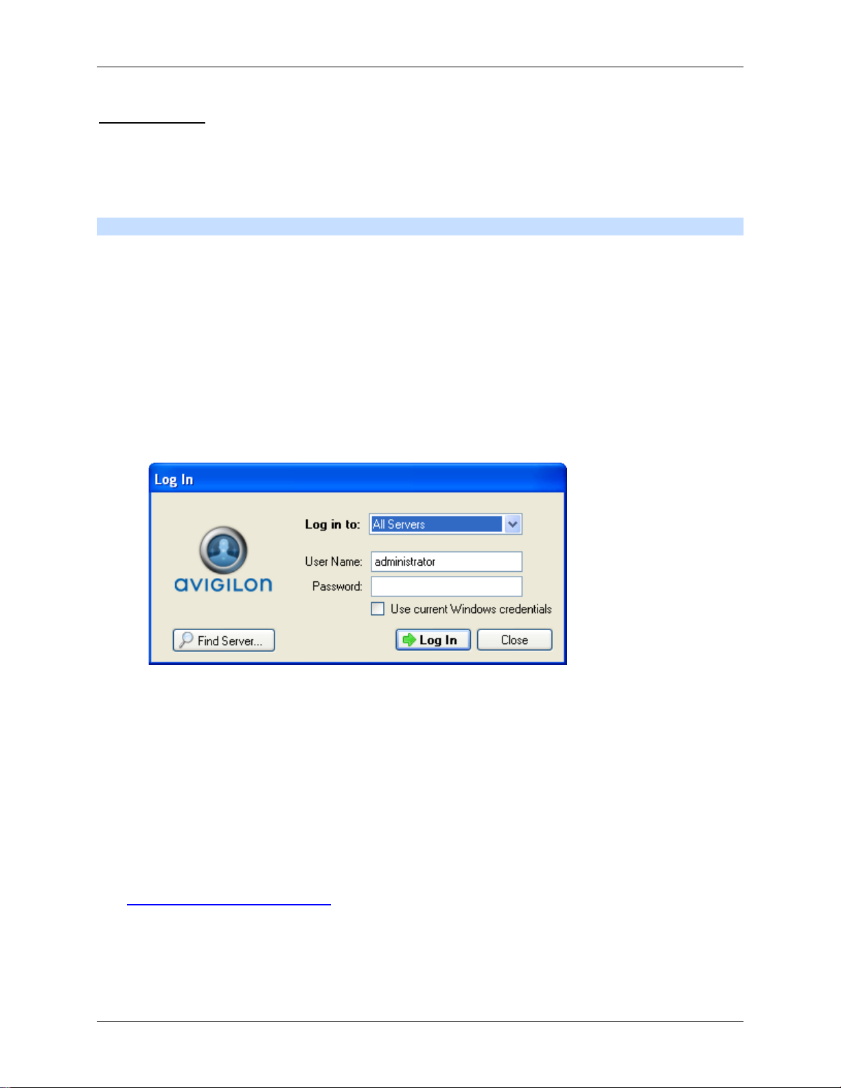
2. In the Log In dialog box, select a specific server or select All Servers from the Log in to drop
down list.
Figure A. Log In dialog box
Tip: If you accessed the Log In dialog box from a specific server, you will not have the
option of logging into All Servers.
If the server you want to log into is not shown, click Find Server... to try to discover the server.
3. Enter your User Name and Password, or select the Use current Windows credentials check
box if your system administrator has imported your Windows account information into the server.
4. Click Log In.
After logging in the first time, you can set up automatic login from the client Setup dialog box.
See Changing General Client Settings
for more information.
7
Page 16

Avigilon Control Center Standard Client User Guide
To
Do this
Logging Out
You can log out of one or all servers at any time.
Log out of one server
Log out of all servers
1. Right-click the server in the System Explorer and select Log
Out.
1. Select File > Log out.
2. When the Log Out dialog box appears, click Yes.
Navigating the Application
Once you log in, the Avigilon Control Center Client application window is where you setup your
surveillance system, monitor video, and view, search, and export recorded video.
Note: Some features are not displayed if the server does not have the required license, or if you do not
have the required user permissions.
8
Page 17
Getting Started
Area
Description
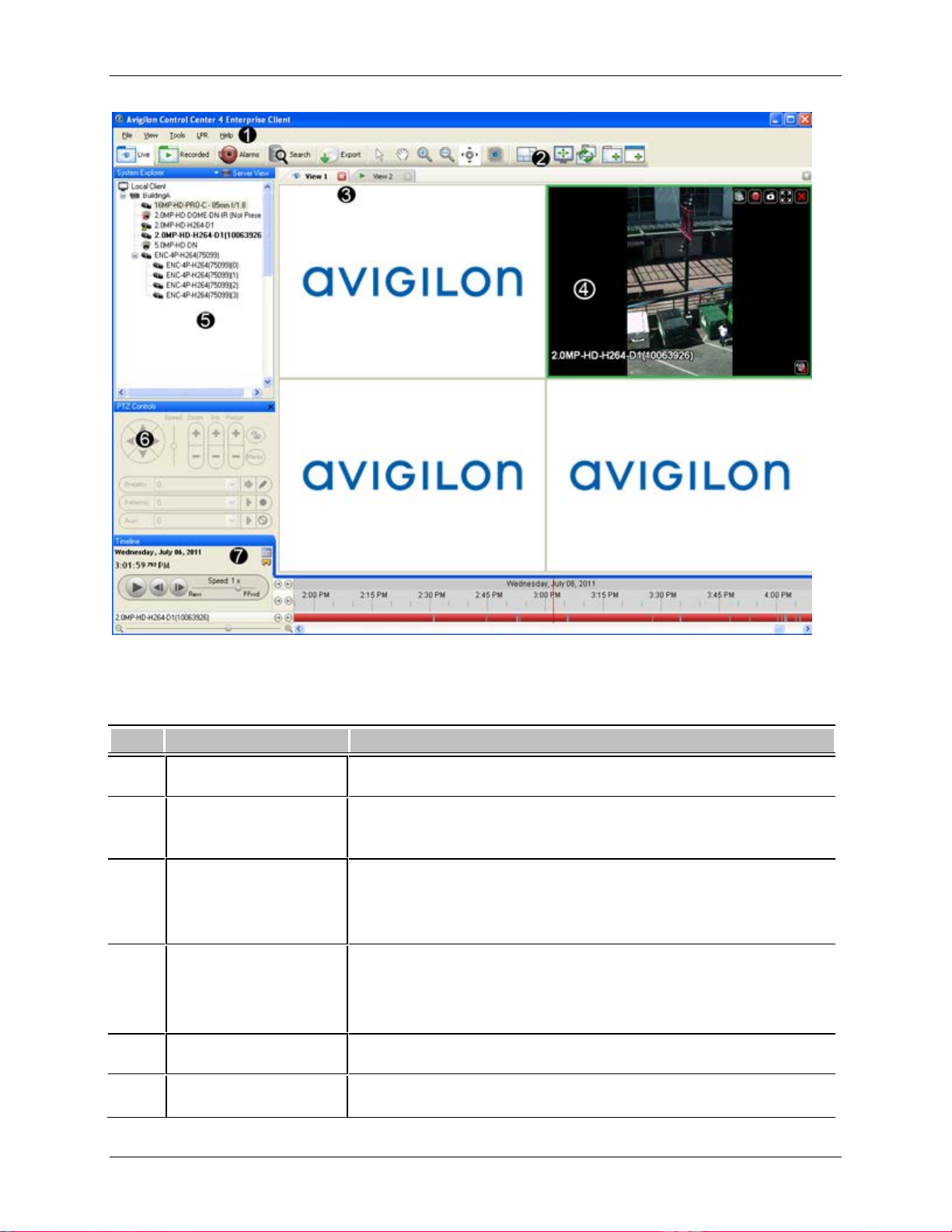
Figure A. Avigilon Control Center Client application window.
Workspace The right pane where the feature tabs appear.
1 Menu bar
A standard Windows application menu that provides access to
features not available on the Toolbar.
Provides quick access to commonly used tools.
2 Toolbar
If any buttons are missing from your toolbar, click the small down
arrow on the right-edge of the toolbar to display the hidden buttons.
Provides a way to organize image panels. You can have multiple
3 View
Views open at once.
This is the most common tab in the Workspace.
4 Image panel Displays live or recorded video from a camera.
5 System Explorer Displays all the servers and cameras in your surveillance system.
9
Page 18

Avigilon Control Center Standard Client User Guide
When you right-click any item in the System Explorer, you have the
option to Expand All or Collapse All items in the System Explorer.
6 PTZ Controls Provides a way to control pan and tilt and zoom (PTZ) cameras.
Displays the Timeline for a recorded video, and contains colorcoded events.
7 Timeline
This tool allows you to review video for a specific time frame, and
control the video playback.
Note: The Timeline only appears for recorded video.
Adding and Removing Cameras in a View
To monitor video, add a camera to the View. The camera video can be removed from the View any time.
Adding a Camera to a View
Perform one of the following:
Drag the camera from the System Explorer to an empty image panel in the View.
Double-click a camera in the System Explorer.
In the System Explorer, right-click the camera and select Add to View.
The camera is added to the next empty image panel in the View layout.
Tip:
You can drag the same camera to multiple image panels to watch the video at differ ent zoom
levels.
Removing a Camera From a View
Perform one of the following:
Right-click the image panel and select Close.
Inside the image panel, click Close.
10
Page 19
Getting Started
Viewing Live and Recorded Video
Note: Some features are not displayed if the server does not have the required license, or if you do not
have the required user permissions.
When you monitor video, you can choose to watch live and recorded video in the same View, or only one
type of video per View.
Once you've added the required cameras to the View, perform the following:
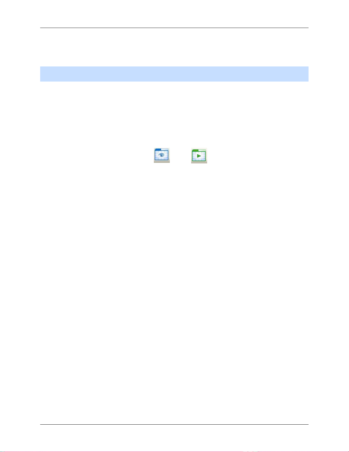
1. To switch the View between live and recorded video, perform one of the following:
o Select View > Live or Recorded.
o On the toolbar, select either Live or Recorded.
2. To switch individual image panels between live and recorded video, right-click the image panel
and select either Live or Recorded.
Image panels displaying live video have a blue border, while image panels displaying recorded video
have a green border.
11
Page 20

Setup
The default settings in the Avigilon Control Center Client software allow you to start working with the
application immediately after installation.
If you have special requirements, refer to the following sections to configure your settings:
Note: Some features are not displayed if the server does not have the required license, or if you do not
have the required user permissions.
Managing Server Connections
When you start the application, you automatically have access to all the servers connected to your
network. If you need to access a server that is on a different network segment, you need to manually
discover the server.
Once you are connected to a server, you can also change how you connect to the server.
Discovering Servers
The Avigilon Control Center Client software must communicate with the Avigilon Control Center Server
software to access and configure your surveillance system. If the server is on the same network segment
(subnet) as your computer, the server is automatically discovered and appears in the System Explorer on
the left side of the application window.
If the server is on a different subnet, the server must be manually discovered. There is no limit to the
number of servers that can be discovered by the Client software.
1. Open the Find Server dialog box.
o In the Log In dialog box, click Find Server....
o In the application window, select File > Manage Server Connections. In the Manage
Servers dialog box, click Find Server...
12
Page 21
Setup
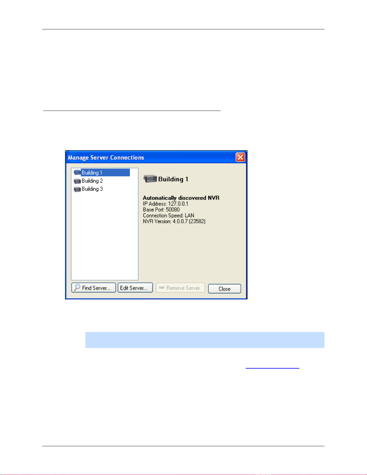
Figure A. Manage Server Connections dialog box
2. In the Find Server dialog box, enter the H ost name / IP Addr ess , the Base Port, and
the Connection Speed of the server you want to discover.
Figure B. Find Server dialog box
The base port is 50080 by default. You can change the base port number in the Avigilon Control
Center Admin Tool. See the Avigilon Control Center Server User Guide for more information.
Tip:
Set the Connection Speed to WAN if you are on a low bandwidth network (for
example, internet or wireless network), and select LAN if you are on a high bandwidth
connection (for example, office or home network). This enables the Avigilon Control Center
to better manage your bandwidth and image rate.
3. Click OK.
If the server is found, the server will appear in the Manage Server Connections dialog box.
If the server is not found, check the following then try again:
13
Page 22
Avigilon Control Center Standard Client User Guide
The network settings are configured correctly.
The firewall is not blocking the application.
The Avigilon Control Center Server software is running on the server.
Editing and Deleting a Server Connection
Use the Manage Server Connections dialog box to edit and delete your server connections.
1. Select File > Manage Server Connections.
Figure A. Manage Server Connections dialog box
2. Select a server on the Server list then perform one of the following:
Note: You cannot remove or edit the IP address and base port of servers that were
automatically discovere d.
o To edit the server connection, click Edit. Update the server I P Address , Base P ort
and Connection Speed as required then click OK. Refer to Discovering Servers
details about the editable options.
o To delete the server connection, click Remove Server.
14
for
Page 23
Setup
Managing User Connections to a Server
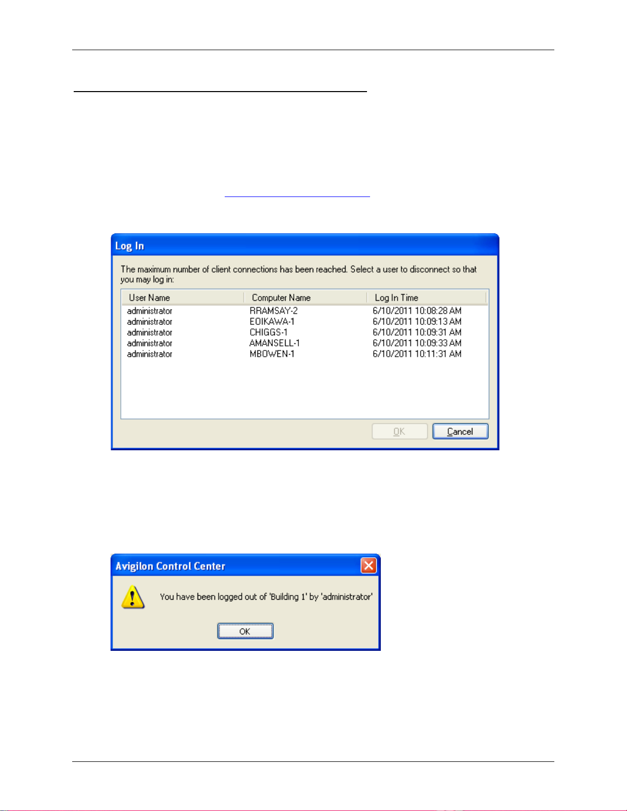
Standard edition servers only allow 5 users to be logged in at the same time. If you are the sixth user to
log in to the server, you will receive an error message.
However, if you are an administrator, or have Manage user session user permiss ions, you ha ve the
option to override another user's login status and replace the user.
1. Log in to the server. See Logging Into and Out of Servers
The following dialog box is displa yed.
Figure A. Log In dialog box
2. Select the user you want to replace.
for more information.
3. Click OK. You will now be logged in to the server.
The user you replaced will see the following message:
Figure B. Logged out message
15
Page 24
Avigilon Control Center Standard Client User Guide
Icon
Definition
Connect/Disconnect Cameras
You can connect and disconnect cameras to servers using the Connect/Disconnect Cameras dialog box.
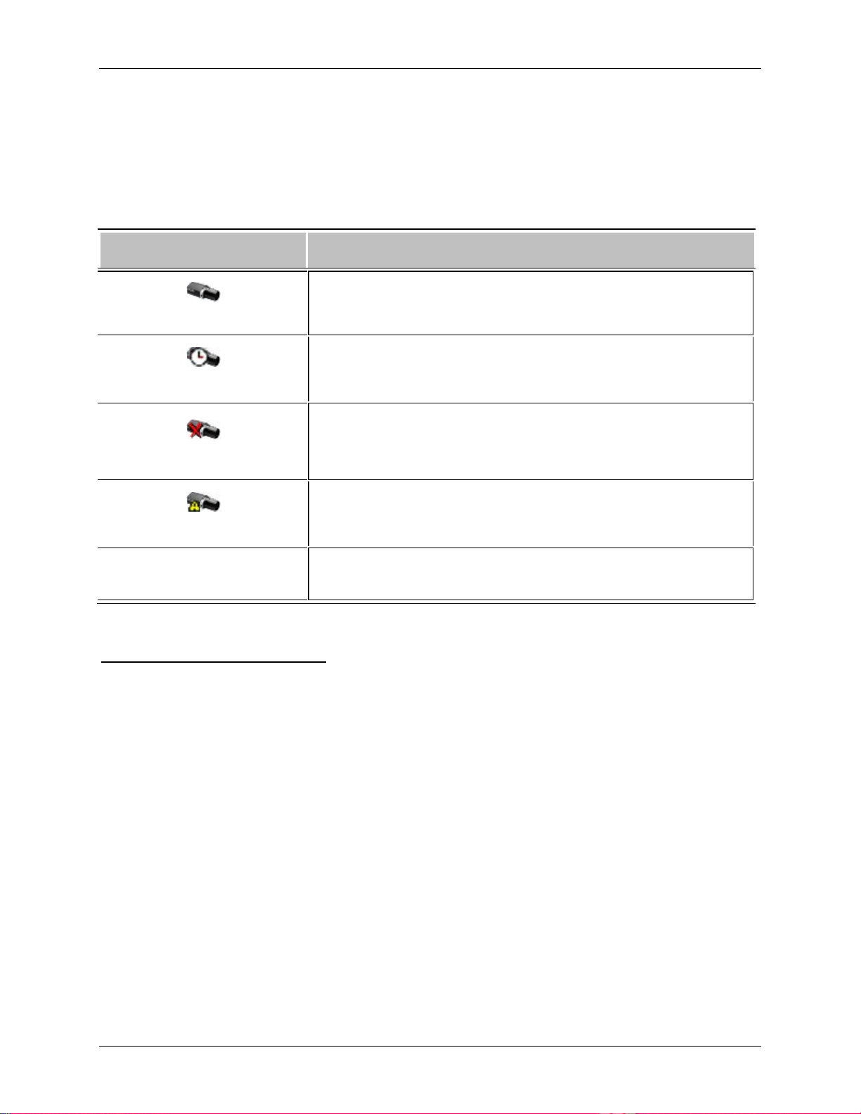
A camera's connection status is indicated by the icon beside the camera name in the System Explorer.
Camera Connected
Camera Upgrading
Camera Connection Error
Camera Disconnected
No icon
The camera is connected to the server.
The camera is connected to the server and is currently upgrading its
firmware.
The camera cannot connect to a server.
This may be because the camera is no longer on the network or
there is a network conflict
The camera is disconnected but there is recorded video from the
camera still on the server.
The camera is disconnected and there is no recorded video left on
the server.
Discovering a Camera
When cameras are connected to the network, they should be automatically discovered by the Avigilon
Control Center Client software.
If a camera is not automatically discovered, you can try to manually discover the camera on the network.
• From the Tools menu, select Connect/Disconnect Cameras.
In the Connect/Disconnect Cameras window, all Avigilon and ONVIF cameras connected to the
same network segment (subnet) as the Avigilon Control Center Server are automatically detected
and appear in the Discovered Cameras list.
If the camera you want to connect to is on a different subnet, or is manufactured by a third party, perform
the following:
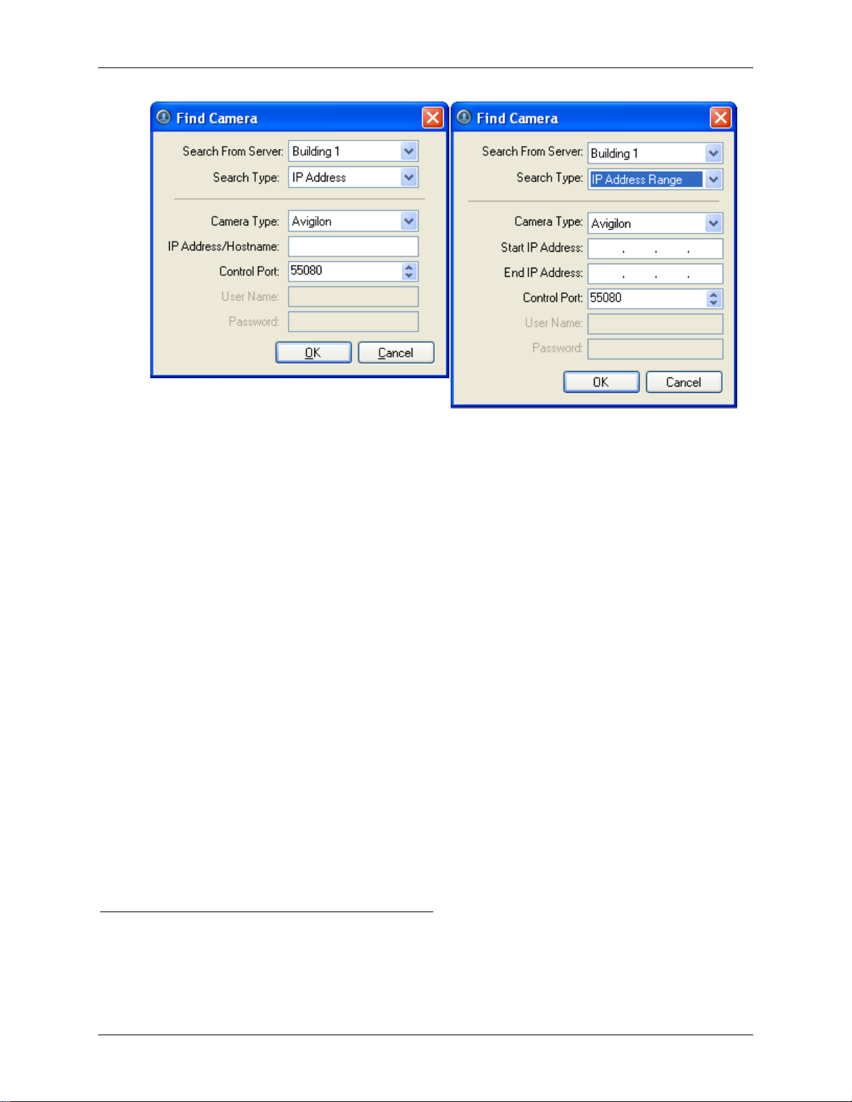
1. At the top of the Connect/Disconnect Cameras dialog box, click Find Camera....
2. In the Find Camera dialog box, complete the following fields:
16
Page 25
Setup
Figure A. Find Camera dialog box: IP Address
Figure B. Find Camera dialog box: IP Address Range
o Search From Server: select the server that you want the camera to connect to.
o Search Type: select a search type.
o Camera Type: select the camera's brand name.
Tip:
Select ONVIF to discover cameras that are ONVIF complaint.
o IP Address/Hostname: (For IP Address search only) enter the camera's IP address or
hostname. The camera and server’s gateway IP address must be set correctly for the
camera to be found.
o Start IP Address and End IP Address: (For IP Address Range search only) enter the
start and end IP addresses. Only addresses in that range will be searched for the
selected camera type.
o Control Port: enter the camera control port number.
o Provide the User Name and Password for the camera if required.
3. Click OK.
If the camera is discovered, it will appear in the Discovered Cameras list. You can now connect the
camera to a server.
Connecting a Camera to a Server
Once the camera has been discovered on the network, it can be connected to the server.
17
Page 26
Avigilon Control Center Standard Client User Guide
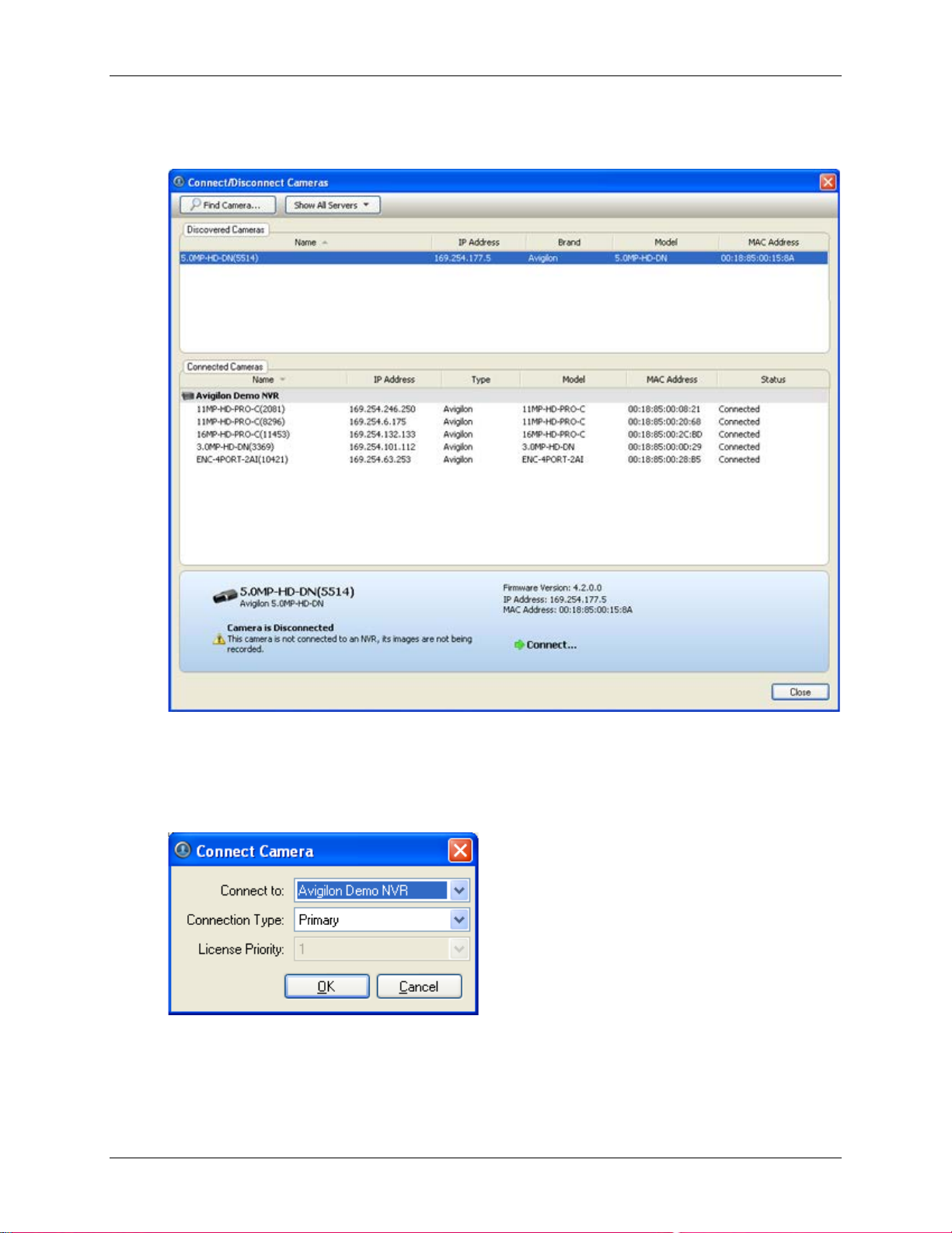
1. From the Tools menu, select Connect/Disconnect Cameras. The Connect/Disconnect Cameras
dialog box appears.
Figure A. Connect/Disconnect Cameras dialog box
2. In the Discovered Cameras area, select a camera then click Connect....
3. In the Connect Camera dialog box, select the server you want the camera to connect to.
Figure B. Connect Camera dialog box
4. Click OK.
18
Page 27
5. If the camera is password protected, the Camera Authentication dialog box appears. Enter the
camera's username and password, then click OK.
Editing the Camera Connection to the Server
1. From the Tools menu, select Connect/Disconnect Cameras.
2. In the Connect/Disconnect Cameras dialog box, select the camera connection you want to edit
from the Connected Cameras list.
Setup
3. Click Edit. Refer to Connecting a Camera to a Server
4. Click OK.
for details about the editable options.
Disconnecting a Camera from a Server
1. From the Tools menu, select Connect/Disconnect Cameras.
2. In the Connect/Disconnect Cameras dialog box, select the camera you want to disconnect from
the Connected Cameras list then perform one of the following:
o Click Disconnect.
The camera is disconnected from the server and moved to the Discovered Cameras list.
o Drag the camera into the Discovered Cameras list.
Upgrading Camera Firmware
Camera firmware updates are typically included with the Avigilon Control Center Server update packages.
Camera firmware updates are automatically downloaded and installed to the camera.
When the camera firmware is being upgraded, video from that camera cannot be displayed and the
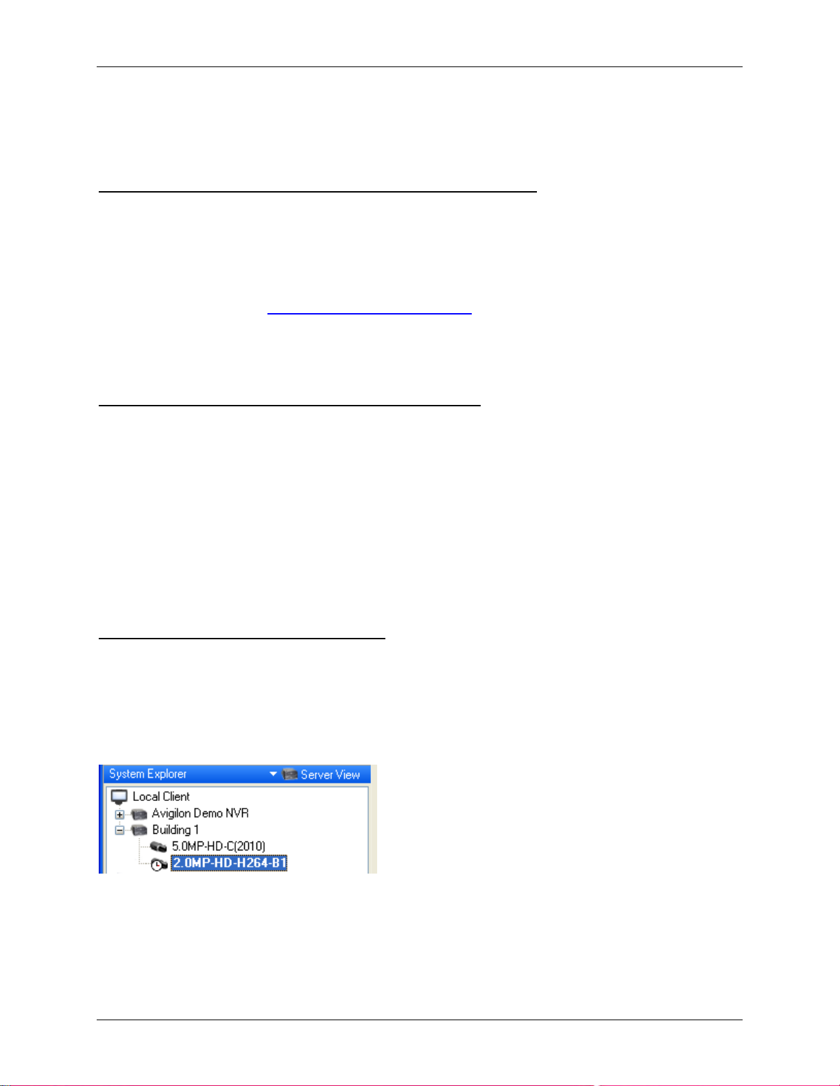
System Explorer will display the following symbol beside the camera.
Figure A. System Explorer: camera firmware upgrade
When the firmware upgrade is complete, the System Explorer will display the Camera Connected icon
again, and video from the camera will display.
19
Page 28

Avigilon Control Center Standard Client User Guide
Server Setup
The server Setup dialog box is responsible for all the Avigilon Control Center features that are configured
and stored on the server.
Refer to any of the following sections to access and configure the server setup.
Note: Some features are not displayed if the server does not have the required license, or if you do not
have the required user permissions.
Accessing the Server Setup
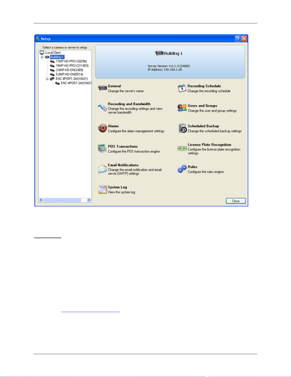
Perform one of the following steps to open the server Setup dialog box:
Select Tools > Setup... then select the server you want to setup from the left pane.
In the System Explorer pane, right-click the server and select Setup.
Note: Some features are not displayed if the server does not have the required license, or if you do not
have the required user permissions.
20
Page 29
Setup
Figure A. Server Setup dialog box
General
Use the General dialog box to change the name the server displays in the System Explorer.
Changing the Server's Name
The default name for the server may not be useful for your purposes. Use the General dialog box to
change the server's name to something more meaningful to your surveillance system.
1. Right-click a server in the System Explorer then select Setup to open the server Setup dialog
box.
See Accessing the Server Setup
2. Click General.
3. In the General dialog box, enter a new server name.
for more information.
21
Page 30

Avigilon Control Center Standard Client User Guide
Figure A. General dialog box
4. Click OK.
Recording Schedule
Use the Recording Schedule dialog box to set the recording schedule for the cameras connected to the
server. By default, the Avigilon Control Center is set to record motion and configured events when they
occur.
Once the recording schedule is set, camera recordings are made automatically.
Using Templates to Modify the Recording Schedule
The recording schedule is set by using templates that tell cameras what to record and when to record.
For example, you can create one recording schedule template for the weekdays and another for the
weekend.
Note: Some features are not displayed if the server does not have the required license, or if you do not
have the required user permissions.
Adding a Template
1. Right-click a server in the System Explorer then select Setup to open the server Setup dialog
box.
See Accessing the Server Setup
2. Click Recording Schedule.
3. In the Recording Schedule dialog box, click Add Template in the Templates pane.
for more information.
22
Page 31

Setup
Record Mode
Definition
Record video constantly.
Only record video when motion is detected.
Only record video when a digital input is activated.
Only record video when point of sale (POS) transactions are made.
Figure A. Schedule dialog box
4. Enter a name for the template.
5. Click the Set Area button then click or drag the cursor across the Record Mode timeline to set
the types of events that the cameras will record throughout the day.
Continuous
Motion
Digital Input
POS Transactions
6. To disable recording in parts of the template, click the C lear Area button then click or drag the
cursor across the timeline to remove the set recording areas.
7. If cameras are not recording in Continuous mode all day, you can set cameras to record
reference images between events in the recording schedule. Select the Record a reference
image every: check box then set the time between each reference image.
Editing and Deleting a Template
1. Right-click a server in the System Explorer then select Setup to open the server Setup dialog
box.
See Accessing the Server Setup
for more information.
2. Click Schedule.
3. In the Schedule dialog box, select a template from the Templates pane and perform one of the
following:
o To edit a template, modify the schedule.
o To rename a template, click Rename Template and enter a new name.
o To delete a template, click Delete Template.
23
Page 32

Avigilon Control Center Standard Client User Guide
4. Click OK.
Setting Up a Weekly Recording Schedule
You can set up a week’s recording schedule by applying templates to cameras for each day of the week.
1. Right-click a server in the System Explorer then select Setup to open the server Setup dialog
box.
See Accessing the Server Setup
2. Click Recording Schedule.
3. In the Recording Schedule dialog box, select a template from the Templates pane.
4. In the Default Week area, select the cameras and days of the week this template applies to.
for more information.
Figure A. Recording Schedule dialog box: Default Week
5. Click OK.
Recording and Bandwidth
While the Schedule dialog box sets what cameras record, the Recording and Bandwidth dialog box sets
how long camera recordings are kept.
You can use the Recording and Bandwidth dialog box to change the data aging settings and maximum
recording times for each camera that is connected to the server.
Changing Recording Settings
1. Right-click a server in the System Explorer then select Setup to open the server Setup dialog
box.
See Accessing the Server Setup
2. Click Recording and Bandwidth. The Recording and Bandwidth dialog box appears.
for more information.
24
Page 33

Setup
Figure A. Recording and Bandwidth dialog box
The Data Aging column shows an estimate of the recording time that is available at each image
rate given the amount of space on the server.
o For JPEG2000 or JPEG compression cameras, data aging is available at three
rates. Full Image Rate and Resolution keeps recordings in its original quality, while Half
Image Rate discards half of the recorded data to make room for new recordings,
and Quarter Image Rate keeps 1/4 of the original recorded data so that you can still see
older video.
o For H.264 cameras that support data aging, data aging is available at two rates. Full
Image Rate and Resolution keeps the original high quality video and the secondary
stream of low resolution video. Low Resolution only keeps the secondary stream of low
resolution video.
Note: Data aging can only occur when the secondary stream is enabled.
o For H.264 cameras that do not support data aging, only the Full Image Rate and
Resolution video is kept.
3. In the Data Aging column, move the sliders to adjust the amount of time video is stored at each
image rate.
o To change the data aging settings for all linked cameras, move the slider for one linked
camera and all linked cameras are updated.
o To change the data aging setting for one camera, break the camera's link to the other
cameras by clicking the Link icon to the left of the camera's name, then make your
changes.
25
Page 34

Avigilon Control Center Standard Client User Guide
4. In the Max. Record Time column, manually enter a maximum record time or select one of the
options from the drop down list for each camera.
Note: If the time estimated in the Total Record Time column is shorter than what is set
in the Max. Record Time column, the camera's actual recording time may be shorter than
what is set.
5. Click OK.
Users and Groups
When users are added to the Avigilon Control Center, they are assigned to an access group that defines
their permissions on the server. Use the Users and Groups dialog box to create and manage users and
groups.
Adding a User
1. Right-click a server in the System Explorer then select Setup to open the server Setup dialog
box.
See Accessing the Server Setu p
for more information.
2. Click Users and Groups.
3. In the User and Groups dialog box, click Add User.
26
Page 35

Setup
Figure A. User and Groups dialog box
4. When the Add User dialog box appears, complete the User Information area.
27
Page 36

Avigilon Control Center Standard Client User Guide
Figure B. Add User dialog box, General tab
5. If you don’t want this user to be active yet, select the Disable user check box. Disabled users are
in the system but cannot access the server.
6. In the Login Timeout area, select the Enable login timeout check box to limit the amount of time
the user can be logged in while the application is idle.
7. In the Password area, complete the following fields:
o Password: enter a password for the user.
o Confirm Password: re-enter the password.
o Require password change on next login: select this check box if the user must replace
the password after the first login.
28
Page 37

Setup
o Password Expiry (Days): specify the number of days before the password must be
changed.
o Password never expires: select this check box if the password never needs to be
changed.
8. Select the Member Of tab and select the check box beside each access group the user belongs
to.
The other two columns display the permissions linked to the selected group.
Figure C. Add User dialog box, Member Of tab
9. Click OK. The user is added to the server.
Editing and Deleting a User
You can edit and delete users as needed.
Note: If a user has access to more than one server, the changes to the user need to be made on each
server.
29
Page 38

Avigilon Control Center Standard Client User Guide
1. Right-click a server in the System Explorer then select Setup to open the server Setup dialog
box.
See Accessing the Server Setup
2. Click Users and Groups.
3. In the Users and Groups dialog box, select a user then perform one of the following:
for more information.
o To edit the user's information, click Edit User. Refer to Adding a User
editable options.
o To delete the user, click Delete User.
Note: Users imported through the Active Directory tab cannot be deleted, only
disabled.
or details about the
Adding Groups
Groups define what features users have access to. Create new groups to tailor what users can access.
1. Right-click a server in the System Explorer then select Setup to open the server Setup dialog
box.
See Accessing the Server Setup
2. Click Users and Groups.
3. In the Users and Groups dialog box, select the Groups tab and click Add Group.
for more information.
30
Page 39

Setup
Figure A. User and Groups dialog box
4. In the Add Group dialog box, select a group to use as a template for your new group and
click OK.
Figure B. Add Group dialog box
5. In the Edit Group dialog box, give the new group a name then select the permissions and camera
access rights for the group.
Clear the check box of any feature or camera you do not want the group to access.
31
Page 40

Avigilon Control Center Standard Client User Guide
Figure C. Edit Group dialog box: Group tab
6. Select the Members tab to add users to the group.
32
Page 41

Setup
Figure D. Edit Group dialog box: Members tab
a. Click Add User....
b. Select the users that should be part of this new group.
33
Page 42

Avigilon Control Center Standard Client User Guide
Figure E. Add users to groups dialog box
c. Click OK. The users are added to the Members list.
If a user is added to the group through the Add User or Edit User dialog box, the user is
automatically added to the group's Members list.
7. Click OK to save the new group.
Editing and Deleting a Group
You can change the access permissions for a set of users by editing their access group.
Note: Active Directory groups can only be deleted from the Active Directory tab.
1. Right-click a server in the System Explorer then select Setup to open the server Setup dialog
box.
See Accessing the Server Setup
2. Click Users and Groups and select the Groups tab.
3. Select a group and perform one of the following:
o To edit the group, click Edit Group. Refer to Adding Groups
options.
for more information.
for details about the editable
34
o To delete the group, click Delete Group.
Note: Default groups cannot be deleted.
Page 43

Setup
POS Transactions
The Point of Sale (POS) Transaction Engine is a licensed feature that records video and raw data from
POS transaction sources. POS transaction sources can be added to the Avigilon Control Center and
configured in the Client software.
Adding a POS Transaction Source
1. Right-click a server in the System Explorer then select Setup to open the server Setup dialog
box.
See Accessing the Server Setup
2. Click POS Transactions.
3. In the POS Transactions dialog box, click Add.
4. Enter the Hostname/IP Address and the Port number for the POS Transaction Source device,
then click Next.
for more information.
Figure A. Set Transaction Source Device page
5. Select a Transaction Source Data format then click Next.
If the source data format needs to be added, click Add. Or, click Copy From to create a new data
format based on the selected data format. See Adding a Transaction Source Data Format
more information.
for
35
Page 44

Avigilon Control Center Standard Client User Guide
Figure B. Set POS Transaction Source Data Format page
6. On the Set Transaction Exceptions page, select any exceptions that need be monitored then
click Next. If exceptions do not need to be monitored, just click Next.
Click Add to add an exception. See Adding a Transaction Exception
for more information.
36
Page 45

Setup
Figure C. Set Transaction Exceptions page
7. Select the cameras to link to the transaction source, and set the amount of time video needs to
be recorded before and after each transaction. Then click Next.
Figure D. Select Linked Cameras page
8. Enter a name and description for the transaction source, then select Enable transaction source
to start receiving data from the transaction source.
37
Page 46

Avigilon Control Center Standard Client User Guide
Figure E. Set Transaction Source Name and Description page
9. Click Finish.
Adding a Transaction Source Data Format
When you add a new POS transaction source, be aware that the transaction source must have a source
data format.
In the POS Transaction Setup wizard, click Add when you arrive on the Set Transaction Source Data
Format page. When the Configure Data Format dialog box appears, complete the following procedure:
1. In the Properties area, specify the following:
38
Figure A. Configure Data Format dialog box
o Name: enter a name for the data format.
Page 47

o Description: enter a description of the data format.
o Transaction Start Text: (required) enter the text that identifies the start of each
transaction from the POS transaction source.
o Transaction End Text: (optional) enter the text that identifies the end of each
transaction.
o Encoding: Select the encoding used by the POS transaction source.
2. The following figure shows raw transaction data on the left and filtered transaction data on the
right. Perform any of the following to capture raw data for the source data format:
Setup
Figure B. Configure Data Format dialog box
o Click Capture Data to start capturing a raw transaction data sample.
o Click Stop Capture to stop capturing transaction data.
o Click Load Data to load raw transaction data from a file.
o Click Save Data to save a copy of the transaction data that has been captured.
3. (Optional) Click Add Filter to create a new filter for the raw transaction data file.
There are two default filters in the Current Filters area: one to create line breaks and the other to
delete extra white space at the beginning of each line. If you do not need extra filters, skip this
step.
39
Page 48

Avigilon Control Center Standard Client User Guide
Figure C. Configure Filter dialog box
2.
a. In the Text field, enter text for the filter to search for.
b. Select Match case and/or Match whole word check box to focus the text filter to only
find text with the same capitalization or match the text exactly.
c. In the Method drop down list, select a search method. You can choose to filter text found
through a Normal search, Wildcard sear ch or Regular Expression search.
d. In the Action to Take area, select which action to take when the filter finds a match to
your text criteria.
e. Click OK.
3. On the Configure Data Format screen, click OK to add the new data format to the data format list.
Adding a Transaction Exception
To help monitor unusual transactions, you can set up transaction exceptions. Transaction exceptions can
help you identify unauthorized discounts, fake returns, and manual price overrides.
In the POS Transac tion Setup w i zard, clic k Add when you arrive on the Set Transaction Exceptions
page. When the Configure Exception dialog box appears, complete the following procedure:
40
Page 49

Setup
Select
And do this...
Enter text for the exception to search for.
The exception will monitor all transactions for the text
entered in the
Enter the value that triggers
text that may appear around the value.
The exception will monitor all transactions for values that
match what you enter in the
When Value
Figure A. Configure Exception dialog box
1. Enter a name.
2. Select one of the Text to Match options:
Match Text
Text to Match field.
the exception, and enter the
Match
Value
Text Before Value, Match
and Text After Value fields
3. Click OK.
Editing and Deleting a POS Transaction Source
1. Right-click a server in the System Explorer then select Setup to open the server Setup dialog
box.
See Accessing the Server Setup
for more information.
2. Click POS Transactions.
41
Page 50

Avigilon Control Center Standard Client User Guide
Figure A. POS Transactions dialog box
3. In the POS Transaction dialog box, select a POS transaction source then perform one of the
following:
o To edit the POS transaction source, click Edit. Go through the POS Transaction Setup
wizard and make the required changes on each page. On the last page, click Finish to
save your changes. Refer to Adding a POS Transaction Source
editable options.
o To delete the POS transaction source, click Delete. When the confirmation dialog box
appears, click OK.
for details about the
Email Notification
Use the Email Notification dialog box to prepare the server for sending email messages in response to
specific events. You can set what events require email notification and who receives the emails.
Setting Up the Email Server
Before emails can be sent, the server must be set up to send emails.
1. Right-click a server in the System Explorer then select Setup to open the server Setup dialog
box.
See Accessing the Server Setup
2. Click Email Notification.
42
for more information.
Page 51

3. In the Email Notification dialog box, select the Email Server tab.
Setup
Figure A. Email Notifications dialog box: Email Server tab
4. In the Email Server Settings area, complete the following
a. Sender Name: enter a name for the server sending out the email.
b. Sender Email Address: enter an email address the server can use to send emails.
c. Subject Line: enter a default subject line for all emails sent from this server.
d. SMTP Server: enter the SMTP server address used by the email.
e. Port: enter the SMTP port.
f. Timeout (seconds): enter the maximum number of seconds the server will try to send an
email before it quits.
5. (Optional) If the email server uses encryption, you can select the Use secure connection
(TLS/SSL) check box.
6. (Optional) If the email account has a username and password, select the Server requires
authentication check box.
a. Enter the Username and Password for the email account.
7. Click OK.
43
Page 52

Avigilon Control Center Standard Client User Guide
Configuring Email Notification
In the Email Notification dialog box, you can create email notification groups to specify who will receive
email notifications when an event occurs.
1. Right-click a server in the System Explorer then select Setup to open the server Setup dialog
box.
See Accessing the Server Setup
2. Click Email Notification.
3. In the Email Notification dialog box, ensure the Email Notification tab is selected.
4. Click Add.
for more information.
Figure A. Email Notifications dialog box
5. Enter a name for the new email group.
44
Page 53

Setup
6. In the Email Recipients area, add all the users, groups and emails that are part of this email
group. Perform any of the following:
o Click Add User/Group to add an Avigilon Control Center user or access group. In the
dialog box, select all the required users and groups then click OK.
o Click Add Email to add individual emails. In the dialog box, enter the email address then
click OK.
Tip:
Make sure the Avigilon users and groups added to the Email Recipient list have a
valid email in their user account.
7. Click Send Test Email to send a test email to everyone on the Em ail Rec ipients li st.
8. In the Email Trigger area, select all the events that this email group will be notified of. Click the
blue text to define the event requirements.
9. To attach a snapshot of the email notification event, select the Attach images from camera(s)
linked to the event check box.
Note: This option is disabled if only System Events is selected because cameras
cannot be linked to System Events.
10. In the Email Schedule area, select a schedule for the email notification. See Scheduling Server
Events for more information.
11. To limit the number of emails sent, enter the amount of time between each email in the Send
email at most every: field.
12. Click OK.
Editing and Deleting an Email Notification
You can edit the details of an email notification or delete the email notification when it is no longer
needed.
1. Right-click a server in the System Explorer then select Setup to open the server Setup dialog
box.
See Accessing the Server Setup
2. Click Email Notification.
3. In the Email Notification dialog box, ensure the Email Notification tab is selected then perform one
of the following:
o To edit the email notification, select the Email Group and make the required changes.
Refer to Configuring Email Notification
for more information.
for details about the editable options.
o To delete the email notification, select the Email Group and click Remove.
45
Page 54

Avigilon Control Center Standard Client User Guide
System Log
The system log records events that occur in the Avigilon Control Center. This can be useful for tracking
system usage and diagnosing issues.
You can filter the items displayed in the log and save the log to a separate file for sending to Avigilon
support.
Note: The system log maintains a record of system events for up to 90 days.
Viewing the System Log
1. Right-click a server in the System Explorer then select Setup to open the server Setup dialog
box.
See Accessing the Server Setup
2. Click System Log.
3. In the System Log dialog box, select the log events you want to display in the Event Types to
Show area, then click Start Search.
for more information.
The search results are displayed in the left pane.
Figure A. System Log dialog box
4. Select a result to display the event details on the right.
46
Page 55

Setup
5. To save the log search results, click Save events to file... and save the file.
6. Click Close.
Scheduling Server Events
Server events are actions triggered with in the A vigi lon Contr o l Center Ser ver that ar e not related to video
recording, like email notifications. When you configure a server event, you are given the option to assign
a schedule for the event. Schedules control when events are enabled — at specific times during a day or
only on specific days.
When you arrive at the scheduling page while configuring an event, you have the option to select an
existing schedule or create a new schedule.
Figure A. Schedule option
1. To use a configured schedule, select an option from the drop down list. The default option
is Always, which allows the event to run constantly.
2. To create or edit a schedule, click .
Figure B. Edit Schedules dialog box.
a. To add a new schedule, click Add then enter a name for the new schedule.
b. To edit a schedule, select a schedule from the list and make the required changes.
c. In the Start and End fields, enter the time the event is enabled for.
d. In the Start Date field, enter when the schedule would begin.
e. In the Recurrence Pattern area, select how often you want the event to be enabled.
47
Page 56

Avigilon Control Center Standard Client User Guide
Option
Description
The event would be enabled every day at the same time.
The event would be
The event would be enabled once a month at the same day and time.
The event would be enabled once a year at the same day and time.
1.
1.
2.
Daily
Weekly
Monthly
Yearly
1.
2. Click OK.
• Select the number of days between each schedule recurrence.
enabled every week at the same day(s) and time.
• Select the day(s) of the week, then select the number of weeks
between each schedule recurrence.
• Select the specific day or weekday, then select the number of
months between each schedule recurrence.
• Select the specific day or weekday and month, then select the
number of years between each schedule recurrence.
Camera Setup
The camera Setup dialog box is responsible for all the features that control cameras and the devices that
can be connected to cameras.
Refer to any of the following sections to access and configure the camera setup.
Note: Some features are not displayed if the server does not have the required license, or if you do not
have the required user permissions.
Note: The dialog box may appear different depending on the camera. Some options are disabled or
hidden if they are not supported by the camera.
Accessing the Camera Setup
Perform one of the following steps to open the camera Setup dialog box:
Select Tools > Setup... then select the camera you want to setup from the left pane.
In the System Explorer pane, right-click the camera and select Setup.
48
Page 57

Setup
Note: Some features are not displayed if the server does not have the required license, or if you do not
have the required user permissions.
Note: The dialog box may appear different depending on the camera. Some options are disabled or
hidden if they are not supported by the camera.
Figure A. Camera Setup dialog box
General
Use the camera General dialog box to set the camera's identity and configure the camera's PTZ settings.
You can also reboot the camera through the General dialog box.
Setting the Camera's Identity
In the camera General dialog box, you can give the camera a name, describe the camera's location, and
give the camera a logical ID. The logical ID is needed to use the select camera keyboard command.
49
Page 58

Avigilon Control Center Standard Client User Guide
Note: The dialog box may appear different depending on the camera. Some options are disabled or
hidden if they are not supported by the camera.
1. Right-click the camera in the System Explorer then select Setup to open the camera Setup dialog
box.
See Accessing the Camer a Setup
for more information.
2. Click General. The General dialog box is displayed.
Figure A. General dialog box
3. In the Camera Name field, give the camera a meaningful name to help you identify the camera.
By default, the camera model number is used as the camera's name.
4. In the Camera Location field, describe the camera's location.
5. In the Logical ID field, enter a unique number to allow applic at ions and in tegr at io n s to identify
this camera.
6. To disable the LEDs on the camera, select the Disable camera status LEDs. This may be
required if the camera is installed in a covert location.
7. If the camera has a motorized zoom and focus lens, the Enable PTZ Controls check box is
displayed. When selected, users can control the camera's zoom and focus through the PTZ
Controls pane. See Controlling PTZ Cameras
for more information.
8. Click OK.
50
Page 59

Setup
Configuring PTZ
Use the camera General dialog box to enable and configure the pan, tilt, zoom (PTZ) features for Avigilon
cameras. PTZ devices are connected to Avigilon cameras through the RS-485 inputs .
Third party PTZ cameras cannot be configured through the Avigilon Control Center.
1. Right-click the camera in the System Explorer then select Setup to open the camera Setup dialog
box.
See Accessing the Camer a Setup
2. Click General. The General dialog box appears.
3. In the PTZ area, select the Enable PTZ check box.
Note: If the following options are not displayed, the camera only has a motorized zoom
and focus lens and cannot perform full PTZ. Selecting the Enable PTZ Controls check
box will allow users to control the zoom and focus through the PTZ Controls pane.
4. In the Protocol drop down list, select the appropriate PTZ protocol. The available protocols
include:
for more information.
o American Dynamics Sensormatic
o AXSYS
o AXSYS DCU
o Ernitec ERNA
o Honeywell Diamond
o Kalatel ASCII
o Pelco D
o Pelco P
o TEB Ligne
o Vicon extended
o Vicon normal
o Videotec Legacy
o Videotec MACRO
5. Enter the Dip Switch Address, Baud Rate and Parity for the PTZ device.
6. Click OK.
51
Page 60

Avigilon Control Center Standard Client User Guide
Rebooting the Camera
You can restart all Avigilon cameras through the camera's General dialog box. This feature is not
available for third party cameras.
1. Right-click the camera in the System Explorer then select Setup to open the camera Setup dialog
box.
See Accessing the Camer a Setup
2. Click General. The General dialog box appears.
3. Click Reboot Camera.
The camera disconnects from the Avigilon Control Center and shuts down. When the camera starts up
again, the camera should automatically reconnect with the Avigilon Control Center.
for more information.
Network
Use the camera Network dialog box to change how a camera connects to the server network.
Note: The dialog box may appear different depending on the camera. Some options are disabled or
hidden if they are not supported by the camera.
Changing Camera Network Settings
1. Right-click the camera and select Setup to open the camera Setup dialog box.
2. Click Network.
3. In the Network dialog box, select how the camera obtains an IP address:
52
Page 61

Setup
Figure A. Network dialog box
o Obtain an IP address automatically: select this option for the camera to connect to the
network through an automatically assigned IP address.
The camera will attempt to obtain an address from a DHCP server. If it cannot, the
camera will default to addresses in the 169.254.x.x range.
o Use the following IP address: select this option to manually assign a static IP address
for the camera.
Enter the IP Address, Subnet Mask and Gateway you want the camera to use.
4. Select the Control Port for connecting to the camera. This port is also used for manually
discovering the camera on the network.
5. Select the Enable Multicast check box to enable multicast streaming from the camera. You must
enable multicast to set up redundant connections to multiple servers.
Use the default generated IP Address, TTL and Base Po rt , or enter your own values.
6. Click OK.
53
Page 62

Avigilon Control Center Standard Client User Guide
Option
Description
Image and Display
Use the Image and Display dialog box to control a camera’s display settings for live and recorded video.
Changing Image and Display Settings
Note: The dialog box may appear different depending on the camera. Some options are disabled or
hidden if they are not supported by the camera.
1. Right-click the camera in the System Explorer then select Setup to open the camera Setup dialog
box.
See Accessing the Camer a Setup
2. Click Image and Display.
3. In the Image and Display dialog box, make the required changes to adjust the camera's image
settings. A preview of your changes are displayed in the image panel.
Tip:
Use the Maximum Exposure, Maximum Gain and Priority options to control low
light behavior.
for more information.
Figure A. Image and Display dialog box
54
Page 63

Exposure
Setup
You can allow the camera to control the exposure by
selecting Automatic, or you can set a specific exposure rate.
Note: Increasing the manual exposure time may affect the
image rate.
Iris
IR Cut Filter
Flicker Control
Backlight
Compensation
Maximum Exposure
Maximum Gain
You can allow the camera to control the iris by selecting Automatic,
or you can manually set it to Open or Closed.
You can allow the camera to control the infrared cut filter by
select Automatic, or set the camera to Color or Monochrome mode.
If your video image flickers because of the fluorescent lights around
the camera, you can reduce the effects of the flicker by setting the
Flicker Control to the same frequency as your lights. Generally,
Europe is 50Hz and North America is 60Hz.
If your scene has areas of intense light that cause the overall image to
be too dark, move the Backlight Compensation slider until you
achieve a well exposed image.
You can limit the automatic exposure setting by selecting a maximum
exposure level.
By setting a maximum exposure level for low light situations, you can
control the camera's exposure time to let in the maximum amount of
light without creating blurry images.
You can limit the automatic gain setting by selecting a maximum gain
level.
By setting a maximum gain level for low light situations, you can
maximize the detail of an image without creating excessive noise in
the images.
Priority
Saturation
Sharpening
You can set Image Rate or Exposure as the priority.
When set to Image Rate, the camera will maintain the set image rate
as the priority, and will not adjust the exposure beyond what can be
recorded for the set image rate.
When set to Exposure, the camera will maintain the exposure setting
as the priority, and will override the set image rate to achieve the best
image possible.
You can adjust the video's color intensity by moving the Color
Saturation slider until the video image meets your requirements.
You can adjust the video sharpness to make the edges of objects
more visible. Move the Sharpening slider until the video image meets
your requirements.
55
Page 64

Avigilon Control Center Standard Client User Guide
Image Rotation
You can change the rotation of captured video. You can rotate the
video 90, 180 or 270 degrees clockwise.
You can control white balance settings to adjust for differences in
light.
White Balance
You can allow the camera to control the white balance by
selecting Automatic, or select Custom and manually set the Red
and Blue settings.
4. To focus the camera, see Focusing the Camera Lens .
5. Click Apply to Cameras... to apply the same settings to other cameras of the same model.
6. Click OK.
Zooming and Focusing the Camera Lens
If you have a camera with a lens capable of electronic zoom and focus, you can zoom and focus the
camera through the Image and Display dialog box.
Note: The dialog box may appear different depending on the camera. Some options are dis abl ed or
hidden if they are not supported by the camera.
1. Right-click the camera in the System Explorer then select Setup to open the camera Setup dialog
box.
See Accessing the Camer a Setup
for more information.
2. Click Image and Display. The Image and Display dialog box appears.
3. If the camera has a built-in auto focus feature, you can choose one of the following:
o Continuous Focus: the camera will automatically focus itself whenever the scene
changes. Skip the following step.
o Manual Focus: you can manually focus the camera through the Image and
Display Focus buttons. Once the focus is manually set, it will not change.
4. While you view the camera image panel, complete the following steps to zoom and focus the
camera:
Tip:
For Avigilon HD Professional cameras, the lens must be set to auto-focus (AF)
mode on the camera. If the camera does not detect the lens, the Focus buttons are not
displayed.
3.
a. Use the Zoom buttons to zoom in to the distance you want to focus.
56
b. In the Iris drop down list, select Open. When the iris is fully open, the camera's depth of
field is the shortest.
Page 65

c. Use the Focus buttons until the image becomes clear.
Button
Description
The camera will automatically focus once.
Focused as close to zero as possible
Large step toward zero
Small step toward zero
Small step toward infinity
Large step toward infinity
Setup
Infinity
4. Click Apply to Cameras... to apply the same settings to other cameras of the same model.
5. Click OK.
Compression and Image Rate
Use the camera Compression and Image Rate dialog box to modify the camera's compression and image
quality settings for sending image data over the network.
Note: The dialog box may appear different depending on the camera. Some options are disabled or
hidden if they are not supported by the camera.
Changing Compression and Image Rate Settings
1. Right-click the camera in the System Explorer then select Setup to open the camera setup dialog
box.
2. Click Compression and Image Rate. The Compression and Image Rate dialog box appears.
57
Page 66

Avigilon Control Center Standard Client User Guide
Figure A. Compression and Image Rate dialog box.
The Bandwidth area gives an estimate of the bandwidth used by the camera with the current
settings. Adjust the settings as required.
Note: For cameras capable of maintaining multiple streams, the settings in this dialog
box only affect the primary stream.
3. In the Format drop down list, select the preferred streaming format.
4. In the Image Rate bar, move the slider to select the how many images per second (ips) you want
the camera to stream over the network.
5. In the Image Quality drop down list, select the desired image quality number.
Image quality setting of 1 will produce the highest quality video and require the most bandwidth.
6. In the Max Bit Rate drop down list, select the maximum bandwidth the camera can use in kilobits
per second (kbps).
7. In the Resolution drop down list, select the preferred image resolution.
8. In the Keyframe Interval drop down list, enter the preferred number of frames between each
keyframe.
9. If your camera supports multiple video streams, you can select the Enable secondary live
viewing stream check box.
When enabled, the secondary live viewing stream is a lower resolution video stream that is
automatically displayed when you monitor live video on a network that does not have enough
bandwidth to display the primary live viewing stream.
58
Page 67

Setup
10. Click Apply to Cameras... to apply the same settings to other cameras of the same model.
11. Click OK.
Image Dimensions
Use the Image Dimension dialog box to set the image dimensions for the camera. You can crop the video
image to help reduce bandwidth and increase the maximum image rate.
Changing Image Dimensions Settings
1. Right-click the camera in the System Explorer then select Setup to open the camera Setup dialog
box.
See Accessing the Camer a Setup
2. Click Image Dimensions.
3. In the Image Dimensions dialog box, adjust the image dimensions by performing one of the
following:
for more information.
o Drag the edges of the image until the video is cropped to fit your requirements.
o Change the values for the Top, Left, Width, and Height field.
Figure A. Image Dimensions dialog box
59
Page 68

Avigilon Control Center Standard Client User Guide
4. Click OK.
Motion Detection
In the Motion Detection dialog box, you can define specific motion detection areas and configure the
camera's sensitivity and threshold for motion.
Selecting an Area to Detect Motion
In the Motion Detection dialog box, you can define the green motion detection areas in the camera's field
of view. Motion detection is ignored in the areas not highlighted in green.
1. Right-click the camera in the System Explorer then select Setup to open the camera Setup dialog
box.
See Accessing the Camer a Setup
2. Click Motion Detection.
for more information.
3. In the Motion Detection dialog box, use the tools above the image panel to define the green
motion detection area:
o Set Area: select this button then draw green rectangles to define the motion detection
areas. You can draw multiple rectangles to create your motion detection area.
o Clear Area: select this button and draw rectangles to erase sections from the motion
detection area.
o Draw: select this button and manually draw motion detection areas with your mouse.
This tool allows you to be very specific and highlight unusual shapes.
o Set All: click this button to highlight the entire image panel for motion detection.
o Clear All: click this button to clear the image panel of motion detection areas.
60
Page 69

Setup
Figure A. Motion Detection dialog box
4. Click OK.
To define the sensitivity and threshold for the motion detection area, see
and Threshold.
Controlling Motion Sensitivity
Controlling Motion Sensitivity and Threshold
In the Motion Detection dialog box, you can control the camera's sensitivity and threshold for motion. You
can also define how much time should be recorded before and after each motion event.
1. Right-click the camera in the System Explorer then select Setup to open the camera Setup dialog
box.
See Accessing the Camer a Setup
2. Click Motion Detection. The Motion Detection dialog box appears.
3. Move the Sensitivity slider to adjust how much each pixel must change before it is considered in
motion.
The higher the sensitivity, the smaller the amount of pixel change is required before motion is
detected.
for more information.
4. Move the Threshold slider to adjust how many pixels must change before the image is
considered to have motion.
The higher the threshold, the higher the number of pixels must change before the image is
considered to have motion.
61
Page 70

Avigilon Control Center Standard Client User Guide
Tip: The Motion indicator above the Threshold slider will move to indicate how much
motion is occurring in the current scene. Only when the motion indicator moves to the right
of the Threshold marker will the camera note the motion.
5. In the Pre-Motion Record Time and Post-Motion Record Time boxes, specify how long video
is recorded before and after the motion event.
6. Click OK.
Privacy Zones
You can set privacy zones in the camera's field of view to block out areas that you do not want to see or
record.
Adding a Privacy Zone
Note: You can add no more than 4 privacy zones per camera.
1. Right-click the camera in the System Explorer then select Setup to open the camera Setup dialog
box.
See Accessing the Camer a Setup
2. Click Privacy Zones.
3. In the Privacy Zones dialog box, click Add and a green box will appear on the image panel.
for more information.
62
Page 71

Setup
Figure A. Privacy Zones dialog box
4. Move and resize the green box until it covers the area you want to block out.
5. If you are adding privacy zones to a PTZ camera, the following two options are displayed above
the image panel.
o Select this option to enable PTZ mode. PTZ mode allows you to pan and tilt the
camera field of view to where the privacy zone needs to be. For details on how to use the
pan and tilt controls, see Controlling PTZ Cameras
o Select this option to disable PTZ mode.
6. Click OK.
.
Editing and Deleting a Privacy Zone
1. Right-click the camera in the System Explorer then select Setup to open the camera Setup dialog
box.
See Accessing the Camera Setup
for more information.
63
Page 72

Avigilon Control Center Standard Client User Guide
2. Click Privacy Zones.
3. In the Privacy Zones dialog box, select a privacy zone from the Privacy Zone list and perform one
of the following:
o To edit the privacy zone, adjust the green box on the image.
o To delete the privacy zone, click Delete.
4. Click OK.
Manual Recording
You can manually set a camera to record events outside of the camera's recording schedule. Manual
recording can only be activated when viewing live video. See Triggering Manual Recording
information.
Use the Manual Recording dialog box to define the maximum manual recording time for each camera.
for more
Changing Manual Recording Settings
1. Right-click the camera in the System Explorer then select Setup to open the camera Setup dialog
box.
See Accessing the Camer a Setup
2. Click Manual Recording. The Manual Recording dialog box appears.
Figure A. Manual Recording dialog box
3. Specify the following:
o Manual Recording Duration: enter how long the camera should record for if recording is
not manually stopped.
for more information.
o Pre-Trigger Reco rd Time: enter the amount of time video is recorded before manual
recording is activated.
4. Click Apply to Cameras... to apply the same settings to other cameras of the same model.
5. Click OK.
64
Page 73

Setup
Digital Inputs and Outputs
Use the Digital Inputs and Outputs dialog box to set up external digital input and output devices that are
connected to the camera.
Setting Up Digital Inputs
1. Right-click the camera in the System Explorer then select Setup to open the camera Setup dialog
box.
See Accessing the Camer a Setup
2. Click Digital Inputs and Outputs.
3. In the Digital Inputs area, select an input.
for more information.
Figure A. Digital Inputs and Outputs dialog box: Digital Inputs Settings
4. Enter a name to identify the digital input.
65
Page 74

Avigilon Control Center Standard Client User Guide
5. In the Recording Duration area, select one of the following:
o Select Follow Event to record the entire digital input event.
o Select Maximum Time to limit the recording time.
6. Enter how long video is recorded before and after the digital input event.
7. Select the digital input's default Circuit State.
8. Select the cameras that should be linked to this digital input.
If the Recording Schedule is configured to record digital inputs, the cameras selected in the Link
to Camera(s) area are used to record all the events triggered by this digital input.
9. Click OK.
Setting Up Digital Outputs
Once a digital output is configured, you can manually trigger the digital output in an image panel.
See Triggering Digital Output
for more information.
Note: The dialog box may appear different depending on the camera. Some options are disabled or
hidden if they are not supported by the camera.
1. Right-click the camera in the System Explorer then select Setup to open the camera Setup dialog
box.
See Accessing the Camer a Setup
2. Click Digital Inputs and Outputs.
3. In the Digital Outputs area, select an output.
for more information.
66
Page 75

Setup
Figure A. Digital Inputs and Outputs dialog box: Digital Output Settings
4. Enter a name to identify the digital output.
5. Select the digital output's default Circuit State.
6. The Trigger Behavior options define what occurs when the digital output is activated.
o Select Activate to enable the digital output in continuous mode. The Duration fields
allow you to specify how long the digital output should be active for.
o Select Pulse to enable the digital output in pulse mode. Specify the Period, Dut y Cycle,
and Repeat Count for the pulse.
7. Select the cameras that should be linked to this digital output.
When the digital output is triggered, all the cameras linked to this digital output begin recording.
8. Click OK.
67
Page 76

Avigilon Control Center Standard Client User Guide
Microphone
Note: Audio recording requires an Audio Channel License.
Use the Microphone dialog box to change the settings for any audio input devices that are connected to
the camera. You can also link the audio to other cameras.
To use this feature, a microphone must be connected to the camera.
Note: The dialog box may appear different depending on the camera. Some options are disabled or
hidden if they are not supported by the camera.
Changing Microphone Settings
1. Right-click the camera in the System Explorer then select Setup to open the camera Setup dialog
box.
See Accessing the Camer a Setup
2. Click Microphone. The Microphone dialog box appears.
for more information.
68
Page 77

Figure A. Microphone dialog box
3. Select the Enable check box to enable audio recording from microphones connected to the
camera.
Note: An error message will appear if you do not have an Audio Channel License.
4. Enter a name for the microphone.
5. In the Source drop down list, select the audio input source.
6. In the Gain drop down list, select the amount of analog gain that is applied to the audio input. The
higher the dB setting, the louder the volume.
7. Click Listen to test the settings and listen to the audio input device.
8. In the Link to Camera(s) area, select the cameras that should be linked to this audio.
9. Click OK.
Speaker
Setup
Note: Audio broadcasting requires a Speaker Channel License.
Use the Speaker dialog box to change the settings for any speakers that are connected to the camera.
You can also link the audio to other cameras.
To use this feature, speakers must be connected to the camera and a microphone must be connected to
your local client.
Note: The dialog box may appear different depending on the camera. Some options are disabled or
hidden if they are not supported by the camera.
Changing Speaker Settings
1. Right-click the camera in the System Explorer then select Setup to open the camera Setup dialog
box.
See Accessing the Camer a Setup
2. Click Speaker. The Speaker dialog box appears.
for more information.
69
Page 78

Avigilon Control Center Standard Client User Guide
Figure A. Speaker dialog box
3. Select the Enable check box to enable audio broadcasting. Speakers connected to the camera
would broadcast audio from the microphone that is connected to the local client.
Note: An error message will appear if you do not have a Speaker Channel License.
4. Select the Record Spea ke r check box to record what is broadcast.
5. Enter a name for the speaker.
6. The Volume slider controls the volume of the speakers.
7. In the Link to Camera(s) area, select the cameras that should be linked to the speakers.
8. To test the microphone level, speak into the microphone. The red bar will move to show the audio
input level.
9. Click OK.
If you want to enable two-way audio, see Microphone
in the client setup section.
70
Page 79

Setup
Client Setup
The client Setup dialog box is responsible for all the Avigilon Control Center features that are configured
and stored on the local client computer.
Refer to any of the following sections to access and configure the client setup.
Accessing the Client Setup
Perform one of the following steps to open the client Setup dialog box.
Select Tools > Setup... and select the local client from the left pane.
In the System Explorer, right-click the local client and select Setup.
Figure A. Setup Local Client dialog box
71
Page 80

Avigilon Control Center Standard Client User Guide
General
Use the client General dialog box to change your local application preferences.
Changing General Client Settings
1. Right-click the local client in the System Explorer then select Setup to open the client Setup
dialog box.
For more information, see Accessing the Client Setup
2. Click General.
3. In the General dialog box, make any required changes:
.
72
Figure A. General dialog box
o Save/restore window layout: select this check box if you want the application to
remember your layout preferences .
o Automatically launch full screen: select this check box if you want the application to
automatically launch in full screen each time it starts.
o Display on-screen messages: select this check box if you want the application to
display event notification messages through the Event pop-u p dial og box. Ev ent
notifications include license plate recognition events, system events and rule events. If
the check box is cleared, all event notifications are hidden.
Page 81

o Cycle dwell time: enter the number of seconds the application waits before it cycles to a
different View. See Cycling Through Views
o Language: select a language from the drop down list to change the application
language. Select Windows Default for the application to automatically display the same
language as the local client.
o Automatically log in to servers: select this check box to automatically log into all
servers that are available on the network.
Select the type of login you use: Windows Authentication — your Windows login;
or Using saved user name and password — your Avigilon Control Center username
and password.
o In the Maximum Incoming Client Bandwidth area, you can set how much bandwidth is
allowed to come into the client. This would include video streaming.
Select Unlimited, or select Other and specify the maximum kilobits per second (kbits/s)
you want to allow.
4. Click OK.
Setup
for more information.
Joystick
Two types of joysticks are supported: standard Microsoft DirectX USB Joysticks and the Avigilon
Professional Joystick Keyboard.
Use the Joystick dialog box to configure the joystick settings.
Configuring a Standard USB Joystick
Use the Joystick dialog box to configure the buttons used in your standard Microsoft DirectX USB joystick.
1. Connect the joystick.
2. Right-click the local client in the System Explorer then select Setup to open the client Setup
dialog box.
For more information, see Accessing the Client Setup
3. Click Joystick.
4. If the joystick is not automatically detected, an error message will appear. Click Scan for
Joysticks....
Note: The error message will not appear if the joystick was detected.
.
When the joystick is detected, the Joystick dialog box appears.
73
Page 82

Avigilon Control Center Standard Client User Guide
Figure A. Joystick dialog box
5. Set up an action for each button on the joystick:
a. Press a button on the joystick and the button label is highlighted in the Joystick dialog
box.
b. Select an action for the button from the drop down list.
c. Repeat this procedure for each button on the joystick.
6. Click OK.
Configuring an Avigilon Professional Joystick Keyboard
The Avigilon Professional Joystick Keyboard is a USB add-on that contains a joystick for controlling zoom
and pan within image panels, a jog shuttle for controlling the Timeline, and a keypad programmed with
the application's keyboard commands. Refer to Keyboard Commands
control the application.
By default, the keyboard is installed in right-hand mode. Use the Joystick dialog box to configure left-hand
mode.
1. Connect the keyboard.
for the keypad commands that
2. Right-click the local client in the System Explorer then select Setup to open the client Setup
dialog box.
For more information, see Accessing the Client Setup
3. Click Joystick.
74
.
Page 83

4. If the keyboard is not automatically detected, an error message will app ear. Clic k Scan for
Joysticks....
Note: The error message will not appear if the keyboard was detected.
When the keyboard is detected, the Joystick dialog box appears.
Figure A. Joystick dialog box
Setup
5. Select the Enable left-hand mode check box.
6. Click OK.
The keyboard is now configured for left-hand mode.
Rotate the keyboard until the joystick is on the left and the jog shuttle is on the right. Reinstall the keypad
cover with the View button labels at the top.
Exporting Settings
You can export your personalized settings from the local client so that the settings can be backed up or
used on a different computer. These settings include general client settings, joystick, maps, saved Views,
web pages and Site View.
To export server settings like Recording Schedules, Users & Groups, POS Source and Device
Connection settings, see the Avigilon Control Center Server User Guide.
Note: Some features are not displayed if the server does not have the required license, or if you do not
have the required user permissions.
Exporting Client Settings
1. Right-click the local client in the System Explorer then select Setup to open the client Setup
dialog box.
For more information, see Accessing the Client Setup
2. Click Export Settings.
.
75
Page 84

Avigilon Control Center Standard Client User Guide
3. Select the settings you want to export.
Figure A. Export Settings dialog box
The General settings include display quality, deinterlacing, manually added servers, image
overlays, and client connection speed.
4. Click OK.
5. In the Save As dialog box, name and save the file.
Exported client settings can only be saved in Avigilon Client Settings File (.avc) format.
Import Settings
Import and use settings that were previously exported from the local client or from a different computer.
Note: The imported settings will overwrite the local client's current settings.
Importing Client Settings
1. Right-click the local client in the System Explorer then select Setup to open the client Setup
dialog box.
For more information, see Accessing the Client Setup
2. Click Import Settings.
3. In the Select File to Import From dialog box, find the Avigilon Client Settings File (.avc) you want
to import then click Open.
.
4. Select the settings you want to import.
76
Page 85

Figure A. Import Settings dialog box
Setup
5. Click OK.
Microphone
If you have a microphone and speaker channel license, you have the option of enabling a two-way audio
system. This allows people in the video to talk with the operator monitoring the video. You have the option
of full-duplex audio, which allows simultaneous communication, or half-duplex, which only allows
communication from one side at a time.
1. Right-click the local client in the System Explorer then select Setup to open the client Setup
dialog box.
For more information, see Accessing the Client Setup
2. Click Microphone. The Microphone dialog box appears.
.
Figure A. Microphone dialog box
o Select the Full-duplex Audio option to enable two-way audio.
77
Page 86

Avigilon Control Center Standard Client User Guide
o Select the Half-duplex Audio option to use the microphone and speakers separately.
3. Click OK.
For more information about the audio features, see Microphone and Speaker
in the camera setup section.
78
Page 87

Views
What are Views?
A View is a tab composed of image panels that allows you to organ ize ho w video is disp layed.
For example, you can choose to display video from multiple cameras at the same time by using different
layouts.
Adding and Removing a View
Views allow you to customize how you monitor video. You can add a new View to an existing window or
open a new View in its own window to make use of multiple monitors. Views can also be removed as
required.
Adding a New View to the Application Window
Perform one of the following:
Select File > New View.
From the toolbar, click the New View button.
Adding a View to a New Window
Perform one of the following:
Select File > New Window.
79
Page 88

Avigilon Control Center Standard Client User Guide
From the toolbar, click the New Window button.
A new window appears. You can now position this window to make use of multiple monitors.
Closing a View from the Application Window
Perform one of the following:
Select File > Close View.
On the View tab, click the Close View button.
Closing a Window
Perform one of the following:
Select File > Close Window.
Click the Close button on the top right corner of the window.
View Layouts
You can organize how video is displayed through View layouts. You can choose to display video from a
different camera in each image panel, or display video from the same camera at different zoom levels.
There are 10 pre-configured layouts that you can edit to fit your needs.
Selecting a Layout for a View
You can organize how video is displayed by selecting a View layout. The figure shows the default View
layouts.
Select View > Layouts > # Division.
On the toolbar, select the Change Layout button then select one of the layout options.
80
Page 89

Views
Figure A. Layouts on the toolbar
Editing a View Layout
If the default View layouts do not fit your surveillance requirements, you can customize a View layout.
1. On the toolbar, select the Change Layout button then select Edit Layouts.
81
Page 90

Avigilon Control Center Standard Client User Guide
Figure A. Layouts on the Toolbar
2. In the Edit Layouts dialog box, select the layout you want to change.
3. Enter the number of Columns and Rows you want in your layout.
4. In the layout diagram, do any of the following to further customize the layout.
82
Page 91

Views
Figure B. Edit Layouts dialog box
o To create a larger image panel, select a grey line to delete the border between two image
panels. When a line is highlighted in red, the line can be deleted.
o To restore an image panel, select a dotted line to divide a large image panel into two.
When a dotted line is highlighted in green, the line can be restored.
o To restore all default View layouts, click Restore Defaults. All custom layouts in the
Layouts list will be replaced.
Note: You can only add or subtract lines to create a rectangular shape.
5. Click OK to save your changes. The previous View layout has been replaced with your
customized layout.
Tip:
The keyboard commands used to access View layouts are linked to the layout's position on the
View Layouts list. For example, if your custom layout is placed at the top of the Layouts list (layout 1), you
can press Alt + 1 to use that layout.
Making a View Full Screen
You can maximize a View to make full use of a monitor.
83
Page 92

Avigilon Control Center Standard Client User Guide
On the toolbar, click Full Screen.
Ending Full Screen
On the toolbar at the top left of the screen, click End Full Screen.
Tip:
The toolbar is hidden when the application is idle. Move your mouse to display the toolbar.
Cycling Through Views
Once you have multiple Views setup, you can cycle through the Views by displaying each one for a few
seconds. This is useful when monitoring a large number of cameras.
1. Activate the Cycle Tab feature:
o From the View menu, select Cycle Views.
o On the toolbar, click Cycle Views.
To change the cycle dwell time, see Changing General Client Settings
for more information.
Saving a View
Once you've set up a View you like, you can save the View for use again in the future. A saved View
remembers the current View layout, the cameras displayed in each image panel, and the image panel
display settings.
Saving a View
1. Select File > Save View.
2. In the Save As dialog box, name the View and click OK.
Your saved view will appear in the System Explorer.
84
Page 93

Figure A. Saved Views
Opening a Saved View
Perform one of the following
In the System Explorer, right-click the saved View and select Open.
Drag the saved View from the System Explorer to the current View in the application or new
window.
Renaming a Saved View
Views
1. In the System Explorer, right-click the saved View and select Rename.
2. In the Rename View dialog box, enter a new name and click OK.
Deleting a Saved View
1. In the System Explorer, right-click the saved View and select Delete.
2. In the confirmation dialog box, click Yes.
85
Page 94

Video
The Avigilon Control Center Client software allows you to monitor live and recorded video from multiple
cameras. While monitoring video, you have access to PTZ controls, digital zoom, audio, manual
recording, digital outputs, and other playback settings.
To watch a video of the application's video features, see the Introduction to Avigilon Control Center Client
and Viewing Live Video training video and the Identifying, Bookmarking, Searching and Exporting Video
training video in the Avigilon Training Center.
Note: Some features are not displayed if the server does not have the required license, or if you do not
have the required user permissions.
Monitoring Live Video
While monitoring live video, you can perform any of the following procedures.
Adding and Removing Cameras in a View
To monitor video, add a camera to the View. The camera video can be removed from the View any time.
Adding a Camera to a View
Perform one of the following:
Drag the camera from the System Explorer to an empty image panel in the View.
Double-click a camera in the System Explorer.
In the System Explorer, right-click the camera and select Add to View.
The camera is added to the next empty image panel in the View layout.
Tip:
You can drag the same camera to multiple image panels to watch the video at different zoom
levels.
86
Page 95

Video
Removing a Camera From a View
Perform one of the following:
Right-click the image panel and select Close.
Inside the image panel, click Close.
Displaying Live Video
Once a camera has been added to an image panel, you can choose to watch the live video stream. You
can set the entire View to display live video, or only set specific image panels to display live video.
Live video have a blue border around the image panel.
To display live video in a View, perform one of the following:
Select View > Live.
On the toolbar, select Live.
To switch a single image panel to display live video, right-click the image panel and select Live.
Using Instant Replay
To review an event that just occurred, you can immediately access recently recorded video through the
instant replay feature.
Right-click the image panel and select one of the instant replay options:
Replay - 30 Seconds
Replay - 60 Seconds
Replay - 90 Seconds
The image panel immediately plays back the camera's most recently recorded video.
Zooming and Panning a Video
The zoom and pan tools allow you to focus on specific regions in a camera video.
87
Page 96

Avigilon Control Center Standard Client User Guide
Using the Zoom Tools
The most common way to zoom in and out of the video image is to rotate the scroll wheel on your mouse.
The software also includes a set of Zoom tools that can be used with your mouse:
1. Select a Zoom tool:
o From the Tools menu, select Zoom In Tool or Zoom Out Tool.
o On the toolbar, click Zoom In Tool or Zoom Out Tool.
2. Click the image panel until you reach the desired zoom depth.
Using the Pan Tools
You can right-click and drag inside an image panel to pan the video image. Or, you can use the Pan tool:
1. Select the Pan tool:
o From the Tools menu, select Pan Tool.
o On the toolbar, click Pan Tool.
2. Drag the video image in any direction inside the image panel.
Monitoring PTZ Cameras
PTZ cameras can be controlled through the image panel onscreen controls or by using the tools in the
PTZ Controls pane.
Be aware that some of tools and features may not be displayed if they are not supported by your camera.
Controlling PTZ Cameras
Pan, Tilt, Zoom (PTZ) controls allow you to control cameras with PTZ features. You can control a PTZ
camera by using the onscreen controls or by using the tools in the PTZ Controls pane.
See Keyboard Comm ands
for other ways to use the PTZ controls.
1. To display the PTZ Controls, perform one of the following:
o From the Tools menu, select PTZ Controls.
o On the toolbar, click PTZ Controls.
88
Page 97

Video
The PTZ Controls are displayed below the System Explorer. If the PTZ Controls are unavailable,
select an image panel that is displaying video from a PTZ camera.
Note: The controls may appear different depending on the camera. Some options are
disabled or hidden if they are not supported by the camera.
Figure A. PTZ Controls
2. To pan or tilt, perform one of the following:
o Click the round Pan/Tilt arrow buttons in the PTZ Controls. The speed of the pan/tilt
movements can be adjusted using the Speed slider.
o In the image panel, drag your mouse from center to move the camera in that direction.
The farther the cursor is from the center of the image panel, the faster the camera will
move.
o If the camera supports Click to Center, click anywhere on the image panel to center the
camera to that point.
89
Page 98

Avigilon Control Center Standard Client User Guide
Action
Control
Procedure
Figure B. PTZ Onscreen Controls
3. Use the other PTZ controls to perform any of the following:
To zoom
To control the Iris or Focus
• Click the and buttons.
• Click the image panel and
use the mouse scroll wheel
to zoom in and out.
• If the camera supports Drag
to Zoom, click and drag to
create a green box to define
the area you want to zoom in
and see.
• Right-click the image panel
and select Zoom Out Full.
Click the and buttons.
To program a PTZ preset
90
1. Move the camera's field of
view into position.
2. In the PTZ Controls pane,
select a preset number and
Page 99

click .
3. In the Preset Name dialog
box, enter a name for the
preset and click OK.
Video
To activate a PTZ preset
To return to the Home
preset position
To program a PTZ pattern
To activate a PTZ pattern
Select a preset and click .
If the PTZ camera supports a Home
preset position, the button is
enabled. Click the button to return
the camera to its Home position.
1. In the PTZ Controls pane,
select a pattern number and
click .
2. Use the PTZ controls to move
the camera and create the
pattern.
3. Click .
In the PTZ Controls pane, select a
pattern number and click .
The pattern will repeat until the
pattern is stopped or another pattern
is run.
To activate a PTZ tour
To activate an auxiliary
command
To display the PTZ camera
onscreen menu
In the PTZ Controls pane, select a
tour number and click .
The tour will repeat until stopped or
until other PTZ controls are used.
To program a PTZ tour,
see Programming PTZ Tours
.
1. Select an aux command
number and click .
2. Click to turn off the
auxiliary output.
1. Click the Menu button.
91
Page 100

Avigilon Control Center Standard Client User Guide
2. In the PTZ Controls pane, use
Use the
the menu.
Use the
selection choices.
Use the
cancel your selections.
To lock the PTZ controls
the Pan/Tilt buttons to
navigate the menu.
Pan/Tilt buttons to navigate
Zoom buttons to modify your
Focus buttons to confirm or
Click .
No other user will be able to use the
PTZ controls for this camera until
you unlock the controls or log out.
Programming PTZ Tours
If the PTZ camera supports guard tours, the tours can be programmed through the PTZ Controls pane.
Tours allow the PTZ camera to automatically move between a series of preset positions, and can be set
to pause at each preset for a specific amount of time for video monitoring.
1. Create all the PTZ presets you need for this tour. See Controlling PTZ Cameras
information.
2. In the PTZ Controls pane, select a tour number then click . The Edit PTZ Tour dialog box is
displayed.
for more
92
 Loading...