

Page 1

Avigilon™ Control Center
Core Client User Guide
Version 5.2.2
Page 2

©2006 - 2014 Avigilon Corporation. All rights reserved. Unless expressly granted in writing, no license is granted
with respect to any copyright, industrial design, trademark, patent or other intellectual property rights of Avigilon
Corporation or its licensors.
AVIGILON, CAPTURE IT WITH CLARITY, HDSM, HIGH DEFINITION STREAM MANAGEMENT (HDSM), THE BEST
EVIDENCE, LIGHTCATCHER and the ACC logo are registered and/or unregistered trademarks of Avigilon
Corporation in Canada and other jurisdictions worldwide. Other product names mentioned herein may be the
unregistered and/ or registered trademarks of their respective owners. ™ and ® are not used in association with
each trademark in this document.
This manual has been compiled and published covering the latest product descriptions and specifications. The
contents of this manual and the specifications of this product are subject to change without notice. Avigilon
reserves the right to make changes without notice in the specifications and materials contained herein and shall
not be responsible for any damages (including consequential) caused by reliance on the materials presented,
including but not limited to typographical and other errors relating to the publication.
Avigilon Corporation
http://www.avigilon.com
Revised: 2014-07-21
PDF-CLIENT5-C-C-Rev2
2
Page 3

Table of Contents
What is the Avigilon™ Control Center Client? 8
System Requirements 8
For More Information 8
Avigilon Training Center 8
Support 9
Upgrades 9
Feedback 9
Getting Started 10
Starting Up and Shutting Down the Control Center Client 10
Starting Up the Client Software 10
Shutting Down the Client Software 10
Logging In to and Out of a Site 10
Logging In 10
Logging Out 11
Navigating the Client 11
Application Window Features 12
System Explorer Icons 13
Adding and Removing Cameras in a View 13
Adding a Camera to a View 13
Removing a Camera from a View 13
Viewing Live and Recorded Video 14
Managing a Site 15
Sites and Servers 15
Discovering Sites 15
Managing Site Logs 17
Managing User Connections 18
Monitoring Server Status 18
Site Settings 20
Accessing the Setup Tab 20
Site Name 21
Exporting Site Settings 21
Importing Site Settings 22
Connecting/Disconnecting Cameras 23
Discovering a Camera 23
Connecting a Camera to a Server 24
3
Page 4

Editing the Camera Connection to a Server 26
Disconnecting a Camera from a Server 27
Upgrading Camera Firmware 27
Users and Groups 27
Adding a User 27
Editing and Deleting a User 30
Adding Groups 31
Editing and Deleting a Group 34
Email Notifications 35
Setting Up the Email Server 35
Configuring Email Notifications 36
Editing and Deleting an Email Notification 38
Scheduling Site Events 38
Server Settings 41
Server Name 41
Recording Schedule 41
Setting Up a Weekly Recording Schedule 41
Using Templates to Modify the Recording Schedule 42
Adding a Template 42
Editing and Deleting a Template 43
Recording and Bandwidth 43
Camera Settings 46
General 46
Setting the Camera's Identity 46
Configuring PTZ 46
Rebooting the Camera 47
Network 48
Image and Display 49
Changing Image and Display Settings 49
Zooming and Focusing the Camera Lens 51
Focus Buttons 51
Dewarping an Immervision Panomorph Lens 52
Compression and Image Rate 53
Image Dimensions 54
Motion Detection 55
Selecting a Motion Detection Area 55
Controlling Motion Sensitivity and Threshold 56
4
Page 5

Privacy Zones 57
Adding a Privacy Zone 58
Editing and Deleting a Privacy Zone 58
Manual Recording 59
Client Settings 60
General Settings 60
Joystick Settings 62
Configuring an Avigilon™ USB Professional Joystick Keyboard For Left-Hand Use 62
Configuring a Standard USB Joystick 63
Video Display Settings 64
Displaying Analog Video in Deinterlaced Mode 65
Displaying Image Overlays 65
Changing Display Quality 66
What are Views? 67
Adding and Removing a View 67
View Layouts 67
Selecting a Layout for a View 67
Editing a View Layout 68
Making a View Full Screen 70
Ending Full Screen Mode 71
Cycling Through Views 71
Monitoring Video 72
Zooming and Panning in a Video 72
Using the Zoom Tools 72
Using the Pan Tools 72
Maximizing and Restoring an Image Panel 72
Maximizing an Image Panel 72
Restoring an Image Panel 72
Making Image Panel Display Adjustments 73
Controlling Live Video 73
Using Instant Replay 73
Triggering Manual Recording 74
Camera Recording States 74
Starting and Stopping Manual Recording 74
PTZ Cameras 74
5
Page 6

Controlling PTZ Cameras 74
Programming PTZ Tours 77
Controlling Recorded Video 79
Playing Back Recorded Video 79
Synchronizing Recorded Video Playback 80
Enabling Synchronized Recorded Video Playback 80
Disabling Synchronized Recorded Video Playback 81
Bookmarking Recorded Video 81
Adding a Bookmark 81
Exporting, Editing, or Deleting a Bookmark 83
Search 84
Performing a Bookmark Search 84
Viewing Bookmark Search Results 85
Performing an Event Search 85
Viewing Event Search Results 86
Performing a Pixel Search 87
Viewing Pixel Search Results 88
Performing a Thumbnail Search 88
Viewing Thumbnail Search Results 89
Export 91
Exporting Native Video 91
Exporting AVI Video 93
Exporting a Print Image 97
Exporting a Snapshot of an Image 98
Exporting Still Images 101
Appendix 103
Event and Trigger Descriptions 103
Email Notification Trigger Descriptions 103
Group Permission Descriptions 104
Updating the Client Software 105
Accessing the Control Center Web Client 106
Reporting Bugs 107
Keyboard Commands 108
Image Panel & Camera Commands 108
View Tab Commands 109
View Layout Commands 109
Playback Commands 110
6
Page 7

PTZ Commands (Digital and Mechanical) 111
7
Page 8

What is the Avigilon™ Control Center Client?
The Avigilon™ Control Center Client software works with the Avigilon™ Control Center Server software to give
you access and control of your Avigilon High Definition Stream Management (HDSM)™ surveillance system.
The Client software allows you to view live and recorded video, monitor events, and control user access to the
Control Center. The Client software also gives you the ability to configure your surveillance system.
The Client software can run on the same computer as the Server software, or run on a remote computer that
connects to the Site through a local area network (LAN) or a wireless area network (WAN).
What you can do in the Client software depends on the Server software edition. There are three editions of the
Server software available: Core, Standard and Enterprise. Visit the Avigilon website for an overview of the
features available in each edition: http://avigilon.com/products/video-surveillance/avigilon-control-
center/editions/
A copy of the Client software can be downloaded from the Avigilon website or installed with the Server
software.
System Requirements
Minimum requirements Recommended requirements
Monitor resolution 1280 x 1024 1280 x 1024
Windows XP with Service Pack (SP) 2 or
OS
CPU Intel Dual Core 2.0 GHz processor Quad Core 2.0 GHz
System RAM 2 GB 2 GB
Video card
Network card 1 Gbps 1 Gbps
Hard disk space 500 MB 500 MB
later, Windows Vista, Windows 7 or
Windows 8 (32-bit or 64-bit)
PCI Express, DirectX 10.0 compliant with
256 MB RAM
Windows 7 (64-bit)
PCI Express, DirectX 10.0 compliant with
256 MB RAM
For More Information
Visit Avigilonat http://www.avigilon.com/ for additional product documentation.
Avigilon Training Center
The Avigilon Training Center provides free online training videos that demonstrate how to set up and use the
Avigilon Surveillance System. Register online at the Avigilon Partner Portal site to begin:
http://avigilon.force.com/login
8 What is the Avigilon™ Control Center Client?
Page 9

Support
For additional support information, visit http://avigilon.com/support-and-downloads/. The Avigilon Partner Portal
also provides self-directed support resources - register and login at http://avigilon.force.com/login.
Regular AvigilonTechnical Support is available Monday to Friday from 12:00a.m. to 6:00p.m. Pacific Standard
Time (PST):
l North America: +1.888.281.5182 option 1
l International: +800.4567.8988 or +1.604.629.5182 option 1
Emergency Technical Support is available 24/7:
l North America: +1.888.281.5182 option 1 then dial 9
l International: +800.4567.8988 or +1.604.629.5182 option 1then dial 9
E-mails can be sent to: support@avigilon.com.
Upgrades
Software and firmware upgrades will be made available for download as they become available. Check
http://avigilon.com/support-and-downloads/ for available upgrades.
Feedback
We value your feedback. Please send any comments on our products and services to feedback@avigilon.com
Support 9
Page 10

Getting Started
Once the Avigilon™ Control Center Client software has been installed, you can start using the Avigilon High
Definition Stream Management (HDSM)™ surveillance system immediately. Refer to any of the procedures in this
section to help you get started.
Starting Up and Shutting Down the Control Center Client
The Control Center Client software can be started or shut down at anytime - video recording is not affected
because it is controlled separately by the Server software.
Starting Up the Client Software
Perform one of the following:
l In the Start menu, select All Programs or All Apps > Avigilon > Control Center Client.
l
Double-click the shortcut icon on the desktop.
l From the Avigilon Control Center Admin Tool, click Launch Control Center Client. See the Avigilon
Control Center Server User Guide for more information.
Log in to your Site when the Log In dialog box appears. See Logging In to and Out of a Site for more information.
Shutting Down the Client Software
1.
In the top-right corner of the Client, select > Exit.
2. In the confirmation dialog box that appears, click Yes.
Logging In to and Out of a Site
To access any of the features in your Avigilon High Definition Stream Management (HDSM)™ surveillance system,
you must log in to a Site.
The default administrator access uses administrator as the username and no password. To maintain the security
of the administrator account, it is recommended that your system administrator immediately create a password
for this account after the first login. Your system administrator can then create user accounts for other users.
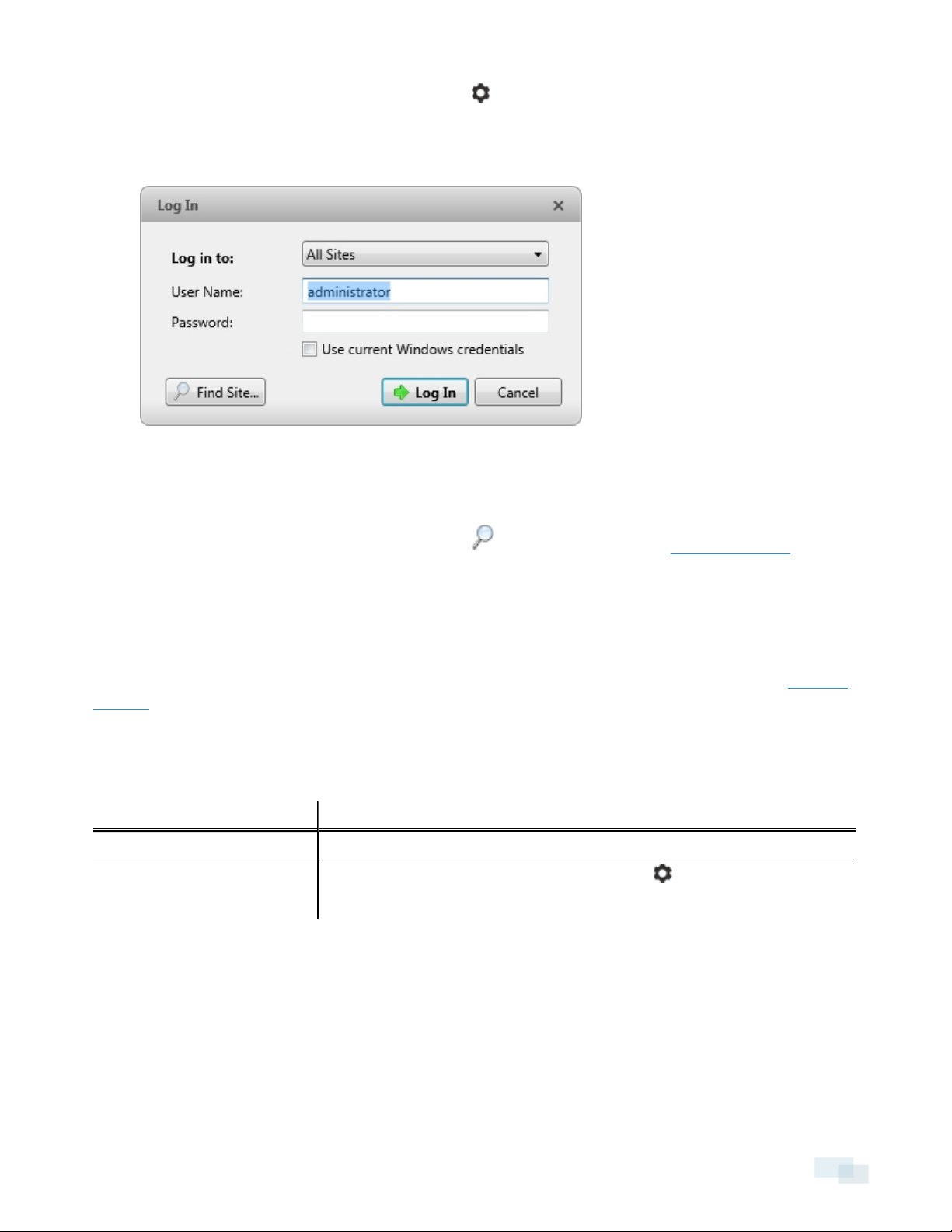
Logging In
1. Open the Log In dialog box. The Log In dialog box automatically appears when the Client software is
launched.
To manually access the Log In dialog box, do one of the following:
10 Getting Started
Page 11
l
In the top-right corner of the Client, select > Log In... to log in to all available Sites.
l In the System Explorer, right-click a Site and select Log In... to log in to the selected Site.
2. In the Log In dialog box, select a specific Site or select All Sites from the Log in to: drop-down list.
Figure 1: Log In dialog box
Tip: If you accessed the Log In dialog box from a specific Site, you will not have the option of logging in
to All Sites.
If the Site you want to log into is not shown, click to discover the Site. See Discovering Sites for more
information.
3. Enter your User Name: and Password:. Or, select the Use current Windows cre dentials check box to
automatically use the same username and password as your computer.
4. Click Log In.
After logging in the first time, you can set up automatic login from the Client Settings... dialog box. See General
Settings for more information.
Logging Out
You can log out of one or all Sites at any time.
To... Do this...
Log out of one Site 1. In the System Explorer, right-click the Site and select Log Out.
1.
Log out of all Sites
In the top-right corner of the Client, select > Log Out.
2. In the confirmation dialog box, click Yes.
Navigating the Client
Once you log in, the Avigilon™ Control Center Client application window is populated with all the features that
are available to you.
NOTE: Some features are not displayedif the server does not have the required license, or if you do not have
the required user permissions.
Logging Out 11
Page 12
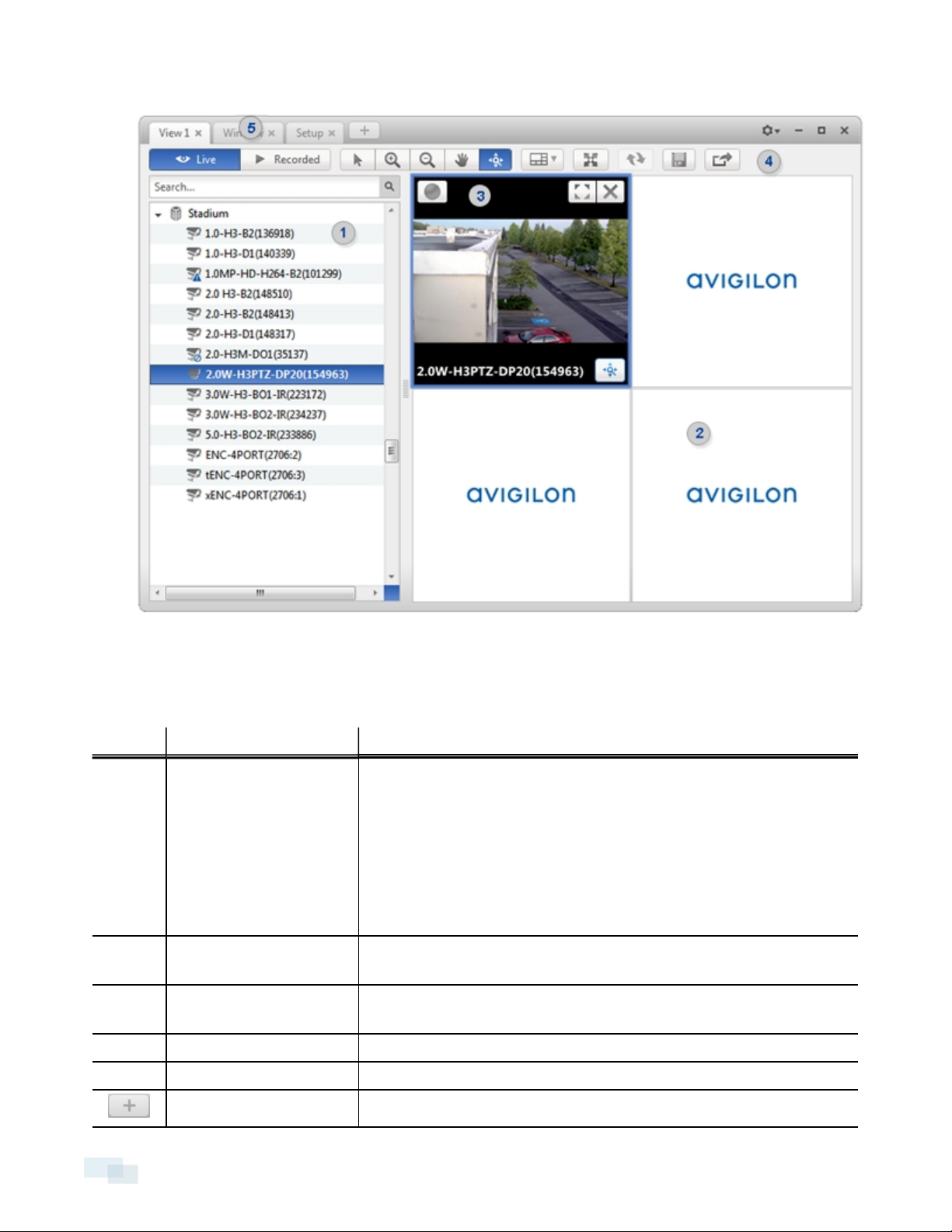
Figure 2: Avigilon Control Center Client application window.
Application Window Features
Area Description
Displays all the elements in your surveillance system.
Use the Search... bar to quickly locate anything that is available in the
System Explorer. You can search for items by name, and devices can
1 System Explorer
also be searched for by location, logical ID, serial number and IP
address.
Tip: The content of the System Explorer changes depending on the tab
you have open. For example, servers are not listed in the View tab.
2 View tab
3 Image panel
Allows you to monitor video and organize image panels. You can have
multiple Views open at once.
Displays live or recorded video from a camera. The video control
buttons are displayed when you move your mouse into the image panel.
4 Toolbar Provides quick access to commonly used tools.
5 Task tabs Displays all the tabs that are currently open.
New Task button
12 Application Window Features
Opens the New Task menu so you can select and open new task tabs.
Page 13
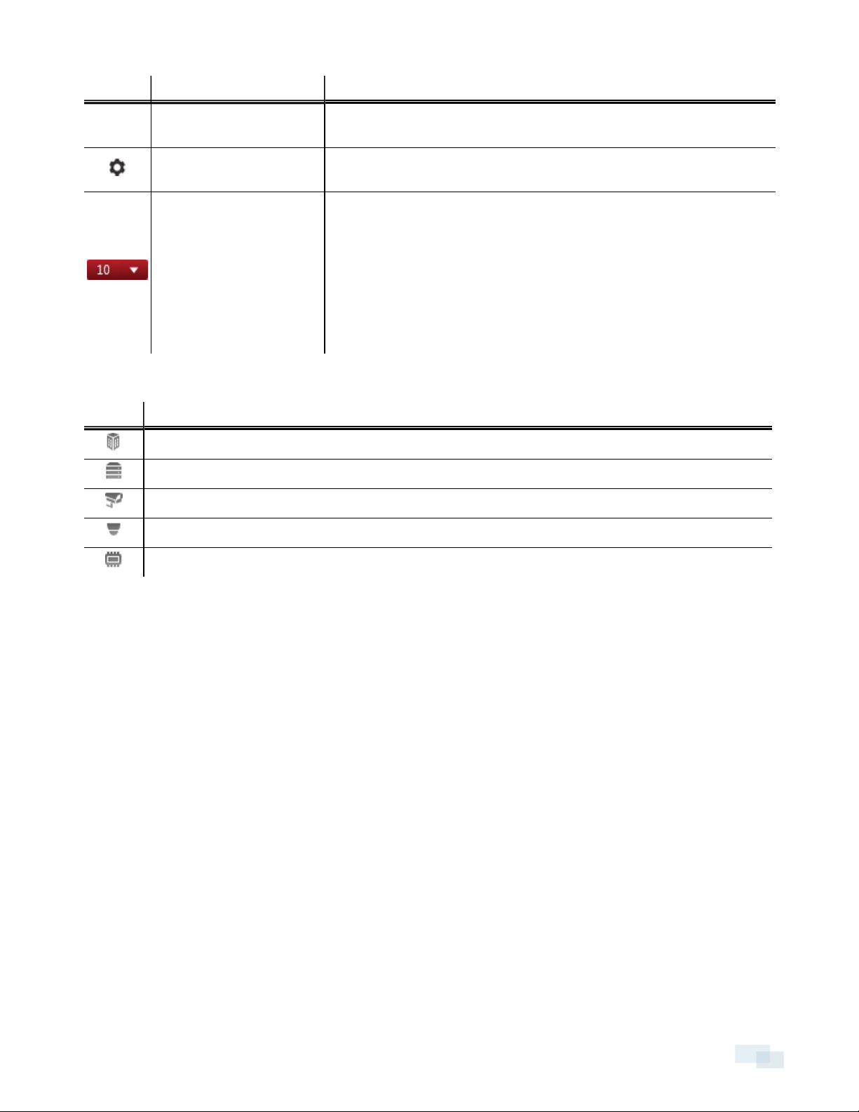
Area Description
You can access advanced tools like Search and Export, or system
administrative features like Site Setup.
Application Menu menu
System message list
This menu gives you access to local application settings like Client
Settings.... You can also open a new window from this menu.
The highlighted number shows the number of system messages that
need your attention. Click the number to display the list of messages.
The highlight color indicates the severity of the most recent message.
l Red = Error
l Yellow = Warning
l Green = Information
System Explorer Icons
Icon Description
A Site. Listed under a Site are all the connected devices and linked features in the system.
A server.
A camera.
A PTZ camera.
An encoder.
Adding and Removing Cameras in a View
To monitor video, add a camera to a View. Camera video can be removed from a View at any time.
Adding a Camera to a View
Do one of the following:
l Drag the camera from the System Explorer to an empty image panel in the View tab.
l Double-click a camera in the System Explorer.
l In the System Explorer, right-click the camera and select Add To View.
The camera is added to the next empty image panel in the View layout.
Tip: You can drag the same camera to multiple image panels to watch the video at different zoom levels.
Removing a Camera from a View
Do one of the following:
System Explorer Icons 13
Page 14

l Right-click the image panel and select Close.
l
Inside the image panel, click .
Viewing Live and Recorded Video
NOTE: Some features are not displayedif the server does not have the required license, or if you do not have
the required user permissions.
When you monitor video, you can choose to watch live and recorded video in the same View, or only one type
of video per View.
Once you've added cameras to the View, perform the following:
l
To switch all of the image panels in the View between live and recorded video, click either Live or
Recorded on the toolbar.
l To switch individual image panels between live and recorded video, right-click the image panel and
select either Live or Recorded.
Image panels displaying recorded video have a green border.
14 Viewing Live and Recorded Video
Page 15

Managing a Site
NOTE: Some features are not displayedif the server does not have the required license, or if you do not have
the required user permissions.
The default settings in the Avigilon™ Control Center Client software allow you to start using the application
immediately after installation. However, you may want to customize and set up your Site to reflect how the
system will be used in daily operations.
In Avigilon Control Center 5, servers are maintained in clusters called Sites.
At the Site level, you can manage your server and camera connections, as well as set up Site-wide system
events.
At the server level, you can manage the recording and bandwidth for each of the server's connected cameras.
At the camera level, you can edit the camera image quality and other camera-specific features.
All the Site, server and camera settings can be configured from the Setup tab.
Sites and Servers
In the Avigilon Control Center software, servers are organized in clusters called Sites. By organizing the system
into clusters, you are able to control user access and system wide events through the Site settings. Site settings
are stored on the server, or across all servers in a multi-server system.
Depending on your system and license edition, you may have multiple servers in a Site. When there are multiple
servers in a Site, the Site is able to distribute tasks and system data between the servers so that the system can
continue running even if a server fails.
Within a Site, each individual server is responsible for managing the devices that are connected to it.
Specifically, the server controls video recording. Through the server settings, you control when video is
recorded, how long it is stored, and how much bandwidth is used to stream video.
Discovering Sites
If your computer is on the same network segment (subnet) as a Site, that Site is automatically discovered and
displayed in the System Explorer.
If the Site you want to access is not listed, it is because the Site is on a different subnet and must be manually
discovered. There is no limit to the number of Sites that can be discovered by the Client software.
By default, when a server is first connected to the system, it is added to a Site with the same name. To locate a
new server, you need to search for its Site.
Managing a Site 15
Page 16
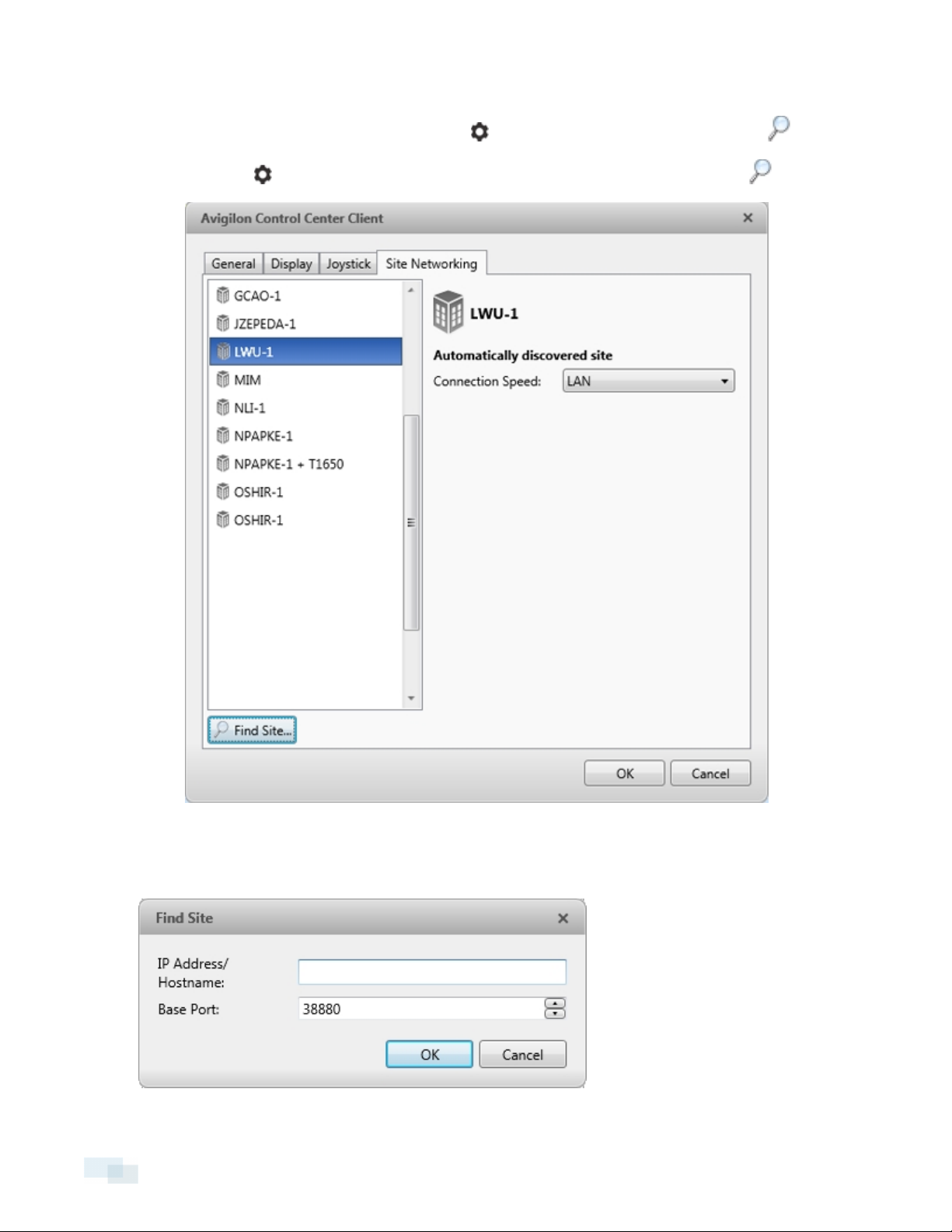
1. Open the Find Site dialog box.
l
In the top-right corner of the Client, select > Log In... . In the Log In dialog box, click .
l
Or, select > Client Settings... > Site Networking. In the Site Networking tab, click .
Figure 3: Site Networking tab
2. In the dialog box, enter the IP Address/Hostname: and the Base Port: of the server in the Site you want to
discover.
16 Discovering Sites
Page 17
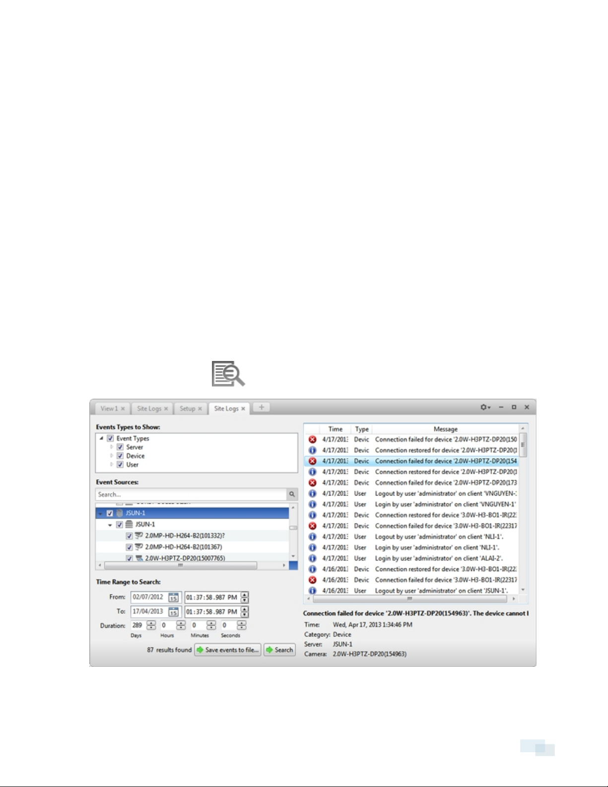
Figure 4: Find Site dialog box
The base port is 38880 by default. You can change the base port number in the Avigilon Control Center
Admin Tool. See the Avigilon Control Center Server User Guide for more information.
3. Click OK.
If the Site is found, it is automatically added to the Site list in the Site Networking tab.
If the Site is not found, check the following then try again:
l The network settings are configured correctly.
l The firewall is not blocking the application.
l The Avigilon Control Center Server software is running on the server you searched for in step 2.
Managing Site Logs
Site Logs record events that occur in the Avigilon Control Center. This can be useful for tracking system usage
and diagnosing issues.
You can filter the items displayed in the log and save the log to a separate file for sending to Avigilon support.
NOTE: Site Logs maintain a record of system events for as long as video data is available or 90 days, whichever
is longer.
1.
In the New Task menu, click .
Figure 5: Site Logs tab
2. In the Site Logs tab, select the Events Types to Show:.
Managing Site Logs 17
Page 18
3. Next, select the specific Sites, servers and cameras whose logs you want to see.
4. In the Time Range to Search: area, set the date and time range of your search.
5. Click Search.
6. Select a result to display its event details.
7. To save the log search results, click Save events to file... and save the file. You can choose to save the
search results as a text file or a CSV file.
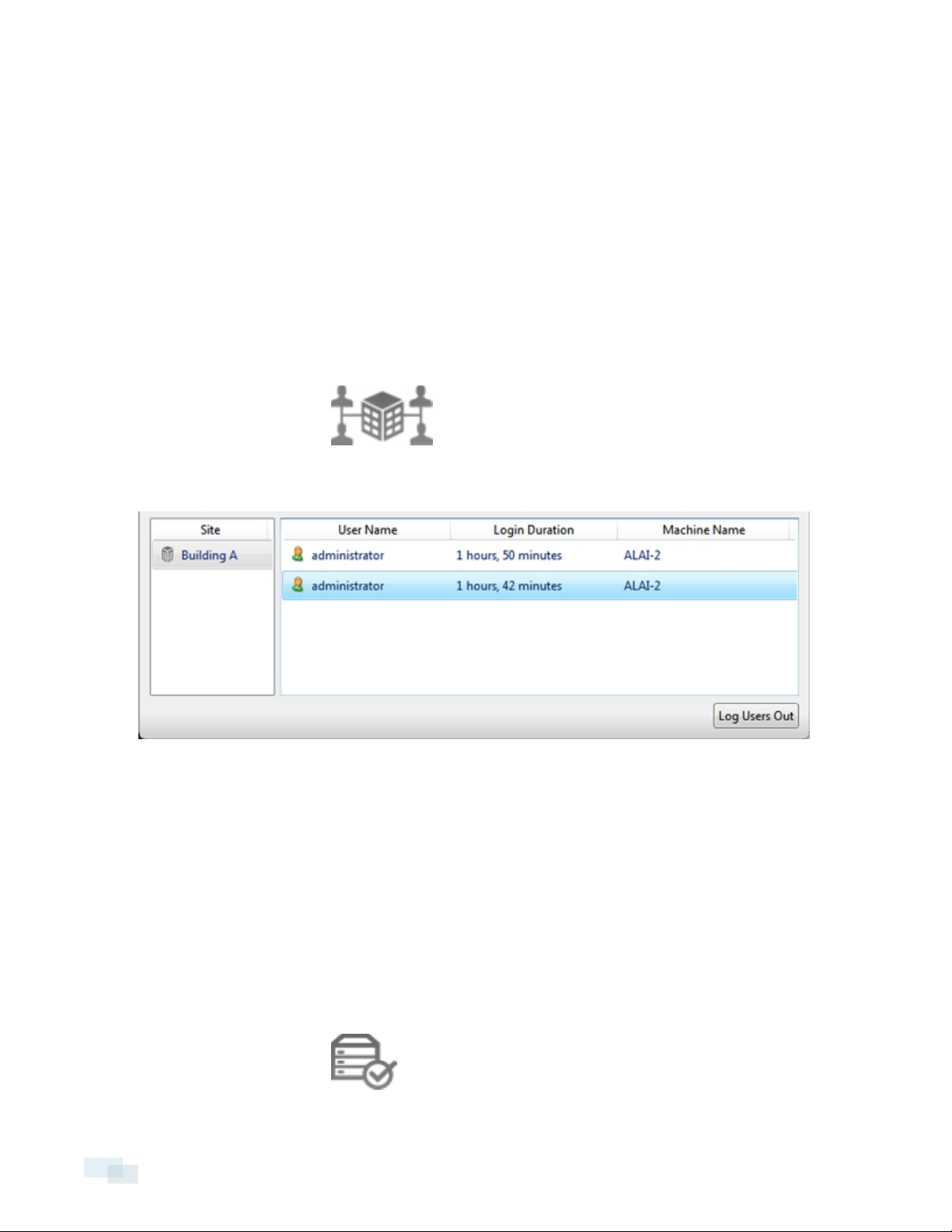
Managing User Connections
If you find that too many users are logged in through the same username or inactive users are preventing active
users from accessing a Site, you can force specific users to log out.
1.
In the New Task menu, click .
2. In the User Connections tab, select a Site from the System Explorer to display a list of all the current users
on the right.
Figure 6: User Conn ection s tab
l The users are listed by username and computer name so that users that share a login are displayed
separately.
l The Login Duration column lets you know exactly how long that user has been logged in to the
Site.
3. To force a user to log out of a Site, select a user then click Log Users Out.
Monitoring Server Status
To help you monitor the health of your Site, you can access a quick overview in the Server Status tab.
l
In the New Task menu, click .
18 Managing User Connections
Page 19
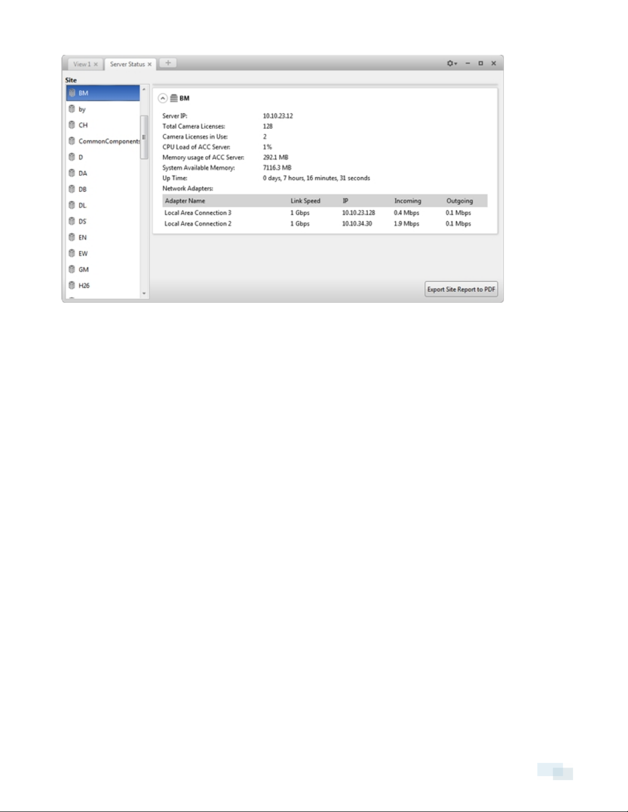
Figure 7: Server Status tab
In the System Explorer, select a Site to display the statuses of connected servers. Listed information includes:
l Server IP: the server's IP address.
l Total Camera Licenses: the total number of camera channel licenses that have been activated on the
server.
l Camera Licenses in Use: the number of cameras that are currently connected to the server.
l CPU Load of ACC Server: the percentage of server processing power used by the Avigilon Control
Center server software.
l Memory usage of ACC Server: the amount of memory used by the Avigilon Control Center Server
software.
l System Available Memory: the amount of storage available for video recording.
l Up Time: the amount of time the server has been running since it was last rebooted.
l Network Adapters: the networks that the server is connected to, including the IP address of the network
connection, the network speed, and the amount of data passing through the connection.
Click Export Site Report to PDF to export the listed server information.
Monitoring Server Status 19
Page 20
Site Settings
The settings stored at the Site level impact all users and devices within the Site.
These settings include user account information and email notifications. This is also where you can add or
remove cameras in a site.
NOTE: Some features are not displayedif the server does not have the required license, or if you do not have
the required user permissions.
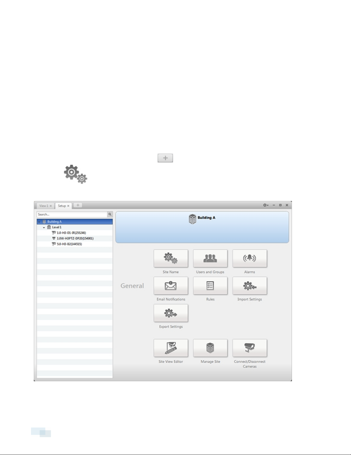
Accessing the Setup Tab
Follow one of the following steps to open the Setup tab:
l
At the top of the application window, click to open the New Task menu. When the menu appears,
click .
l In the System Explorer, right-click the device you want to configure, then select Setup.
Figure 8: Setup tab
20 SiteSettings
Page 21
In the Setup tab, the System Explorer is displayed on the left and the Setup options are displayed on the right.
The Setup options change depending on the device that is selected in the System Explorer.
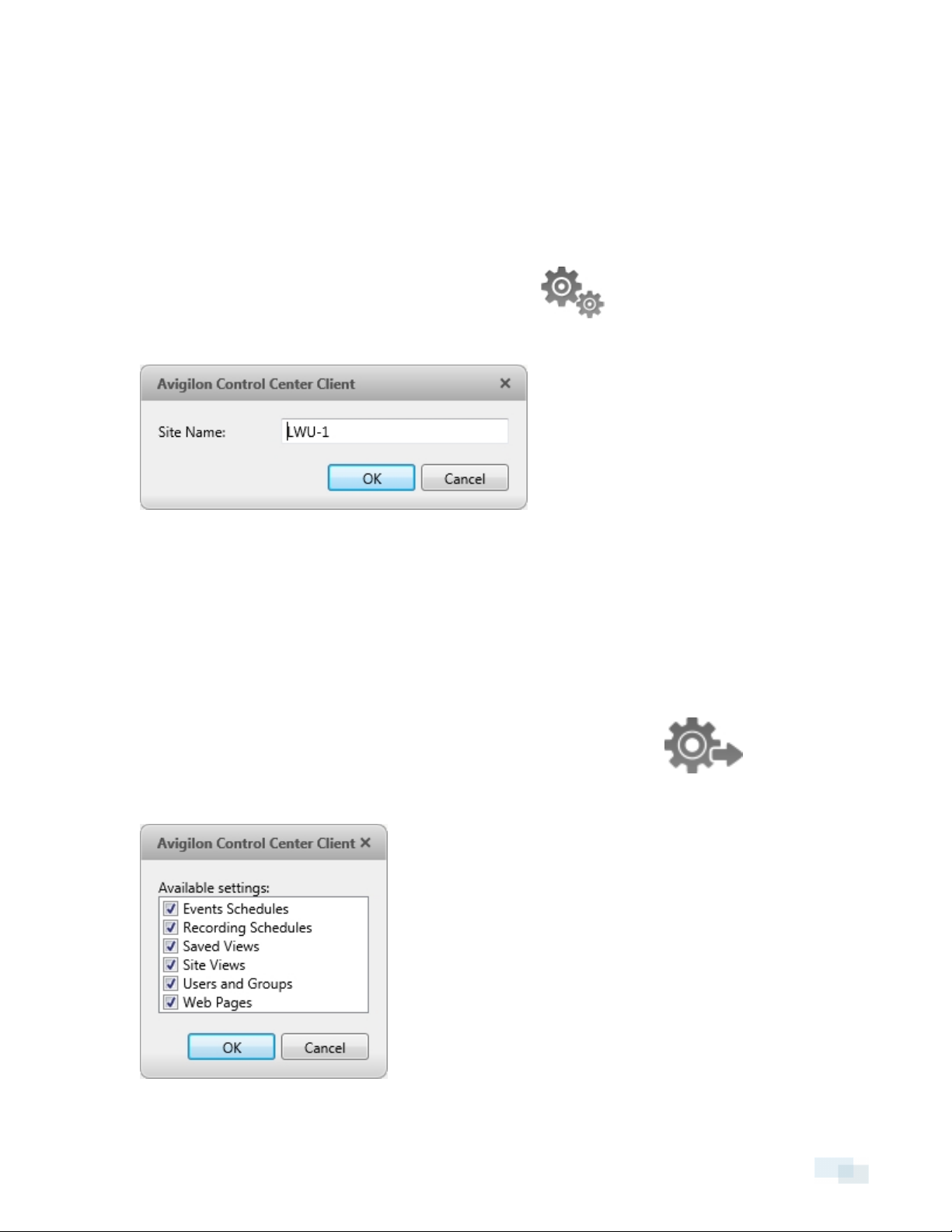
Site Name
Give the Site a meaningful name so that it can be easily identified in the System Explorer. Otherwise, the Site
uses the name assigned to the server it was originally discovered with.
1.
In the Setup tab, select the Site you want to edit, then click .
2. In the dialog box that appears, give the Site a name.
Figure 9: Site Name: dialog box
Exporting Site Settings
You can export Site settings so that they can be backed up or used on a different Site.
NOTE: Some features are not displayedif the server does not have the required license, or if you do not have
the required user permissions.
1.
In the Setup tab, select the Site whose settings you want to export, then click
2. Select the settings you want to export.
SiteName 21
Page 22
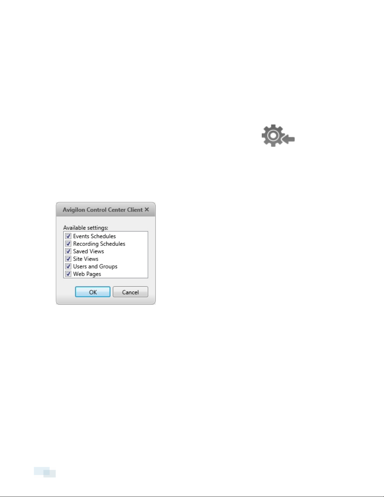
Figure 10: Export Settings dialog box
3. Click OK.
4. In the Save As dialog box, name and save the file.
Exported client settings can only be saved in Avigilon Settings File (.avs) format.
Importing Site Settings
You can import and use settings that were previously exported from a Site.
1.
In the Setup tab, select the Site to you want to import settings to, then click
2. In the Select File to Import dialog box, find the Avigilon Settings File (.avs) you want to import then click
Open.
NOTE: .avc files are not compatible with this version of the Avigilon Control Center Client software.
3. Select the settings you want to import. Only the settings included in the .avs file are displayed.
Figure 11: Import Settings dialog box
4. Click OK.
The settings are merged.
l Unique settings are added to the Site.
l If the settings are identical, only the current Site version is kept.
l If an import setting and a Site setting have the same name but are configured differently, the import
setting is added to the Site and renamed in this format: <setting name> (Import), like Email1 (Import).
l User permission groups are merged.
l If groups have the same name, the import settings are used and the users from both the
import file and the current Site are added to the group.
22 Importing Site Settings
Page 23

l Groups added from the import file automatically gain access to all the new devices that
were added since the settings were exported.
l Users with the same name will use the import settings, including passwords.
Connecting/Disconnecting Cameras
Cameras are connected to a Site through the linked servers. The server manages and stores the camera's
recorded video, while the Site manages the events that can be linked to the camera's video.
You can connect and disconnect cameras through the Connect/Disconnect Cameras... tab.
A camera's connection status is indicated by the icon beside the camera name in the System Explorer. The
status icons may appear over any device icon in the System Explorer.
Icon Definition
The camera is connected to the server.
Camera Connected
The camera is connected to the server and is currently upgrading its
Camera Upgrading
firmware.
The camera cannot connect to a server.
Camera Connection Error
Camera Disconnected
No Icon
This may be because the camera is no longer on the network or there is a
network conflict
The camera is disconnected but recorded video from the camera remains
on the server.
The camera is disconnected and no recorded video from the camera
remains on the server.
Discovering a Camera
When cameras are connected to the network, they should be automatically discovered by the Client.
If a camera is not automatically discovered, you can try to manually discover the camera.
l
In the Setup tab, select a Site then click .
In the Connect/Disconnect Cameras... tab, all Avigilon and ONVIF cameras that are connected to the
same network segment (subnet) are automatically detected and appear in the Discovered Cameras list.
If the camera you want to connect to is on a different subnet, or is manufactured by a third-party, do the
following:
1. At the top of the Connect/Disconnect Cameras... tab, click Find Camera....
2. In the Find Camera dialog box, complete the following fields:
Connecting/Disconnecting Cameras 23
Page 24
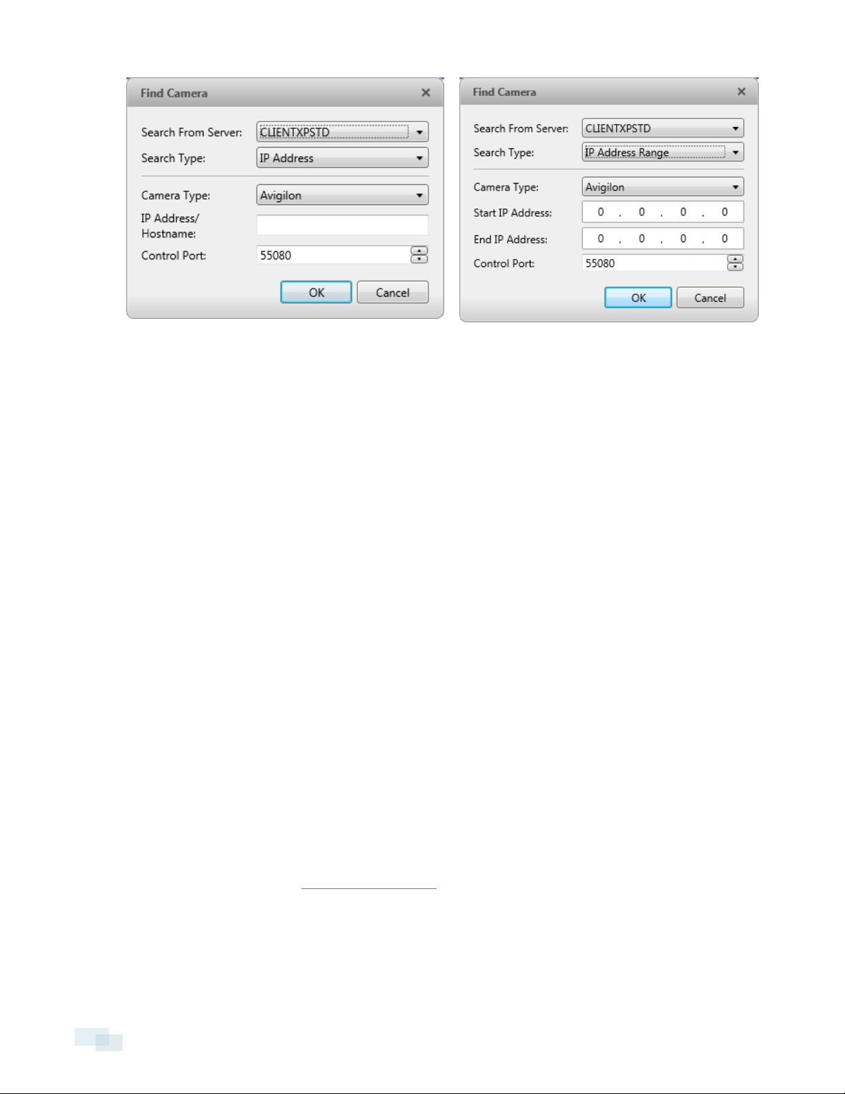
Figure 12: Find Camera dialog box: Search Type - IP Address Figure 13: Find Camera dialog box: Search Type - IP Address
Range
l Search From Server: select the server that you want the camera to connect to.
l Search Type: select a search type.
l Camera Type: select the camera's brand name.
Tip: Select ONVIF to discover cameras that are ONVIF complaint.
l IP Address/Hostname: (For IP Address search only) enter the camera's IP address or hostname. The
camera and server’s gateway IP address must be set correctly for the camera to be found.
l Start IP Address: and End IP Address: (For IP Address Range search only) enter the start and end IP
addresses. Only addresses in that range will be searched for the selected camera type.
l Control Port: enter the camera control port.
l Provide the User Name: and Password: for the camera if required.
3. Click OK.
If the camera is discovered, it will appear in the Discovered Cameras list. You can now connect the camera to a
server.
Connecting a Camera to a Server
NOTE: Some features are not displayedif the server does not have the required license, or if you do not have
the required user permissions.
To access a camera from a Site, it must be connected to server within the Site. The server manages and stores
the camera's recorded video, while the Site manages the events that can be linked to the camera's video.
Once the camera has been discovered on the network, it can be connected to the server. If you do not see the
camera you want to connect to, see Discovering a Camera.
24 Connecting a Camera to a Server
Page 25
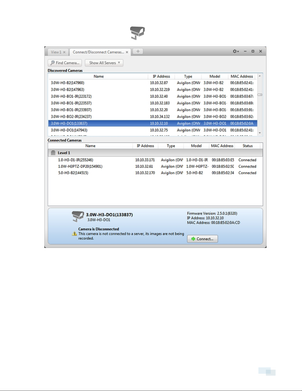
1.
In the Setup tab, select a Site then click .
Figure 14: Connect/Disconn ect Cameras... tab
2. In the Discovered Cameras area, select a camera then click Connect....
Tip: You can also drag the camera to a server on the Connected Cameras list.
Connectinga Camera to a Server 25
Page 26
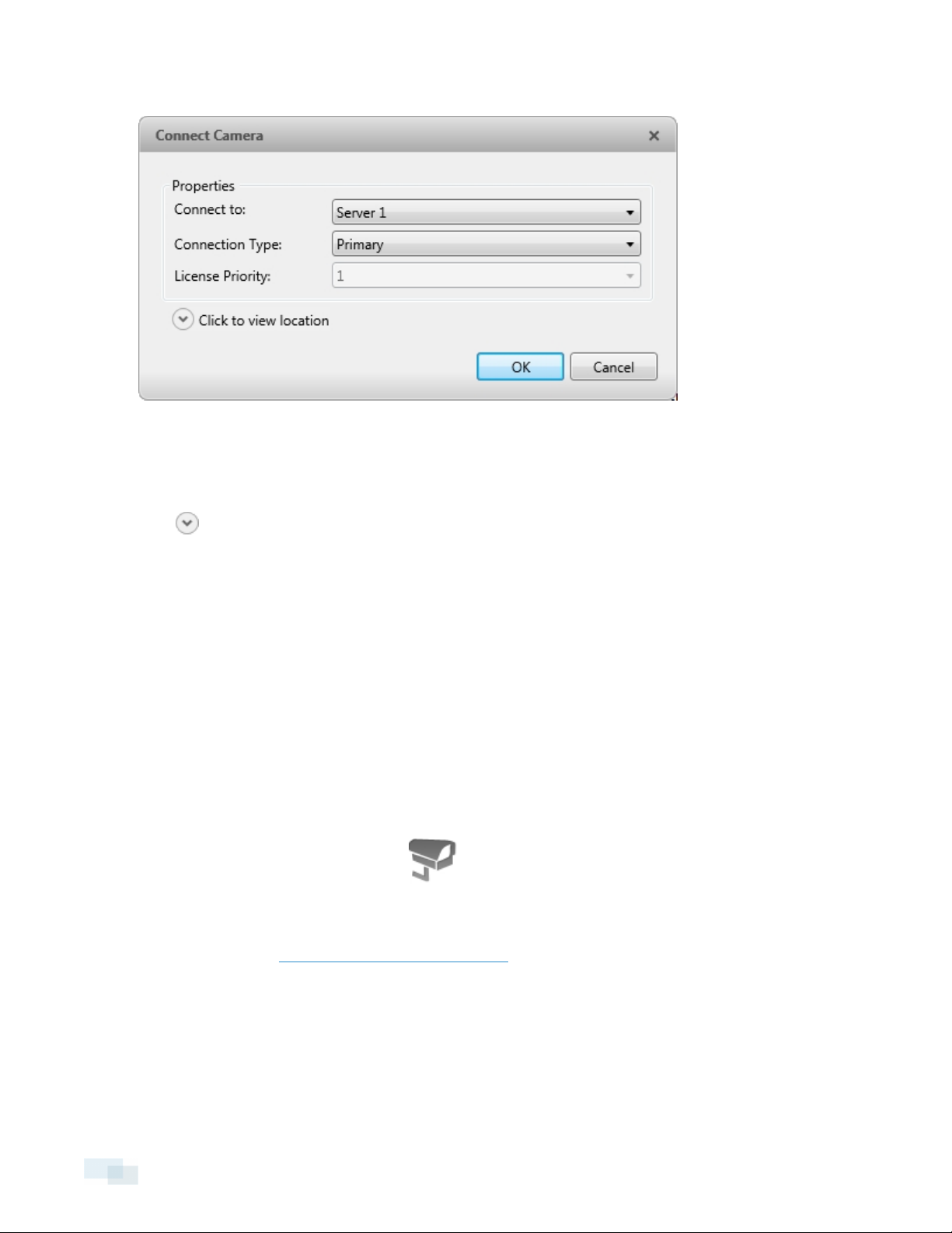
3. In the Connect Camera dialog box, select the server you want the camera to connect to.
Figure 15: Connect Camera dialog box
4. If you are connecting a third-party camera, you may choose to connect the camera by its native driver. In
the Camera Type: drop-down list, select the camera's brand name. If there is only one option in the drop-
down list, the system only supports one type of driver from the camera.
5.
Click to choose where the camera appears in the System Explorer.
l If your Site includes virtual sub-sites, select a location for the camera. The list on the right updates
to show what is stored in that directory.
l In the Site directory, drag the camera up and down to set where it is displayed.
Tip: If the Site you want is not listed, you may need to connect the camera to a different server. Make sure
the selected server is connected to the Site you want.
6. Click OK.
7. If the camera is password protected, the Camera Authentication dialog box appears. Enter the camera's
username and password, then click OK.
Editing the Camera Connection to a Server
NOTE: You can only edit manually discovered camera connections.
1.
In the Setup tab, select a Site then click .
2. In the Connect/Disconnect Cameras... tab, select the camera connection you want to edit from the
Connected Cameras list.
3. Click Edit.... Refer to Connecting a Camera to a Server for details about the editable options.
4. Click OK.
26 Editing the Camera Connection to a Server
Page 27

Disconnecting a Camera from a Server
1.
In the Setup tab, select a Site then click .
2. In the Connect/Disconnect Cameras... tab, select the camera you want to disconnect from the Connected
Cameras list, then do one of the following:
l Click Disconnect. The camera will be disconnected from the server and moved to the Discovered
Cameras list.
l Drag the camera into the Discovered Cameras list.
Upgrading Camera Firmware
Camera firmware updates are typically included with the Avigilon™ Control Center Server update packages.
Camera firmware updates are automatically downloaded and installed to the camera.
When the camera firmware is being upgraded, video from that camera cannot be displayed and the System
Explorer will display beside the camera name.
When the firmware upgrade is complete, the System Explorer will display again and video from the camera
will display.
Users and Groups
When users are added to the AvigilonControl Center, they are assigned to a group that defines their access
permissions in a Site. Use the Users and Groups dialog box to create and manage users and groups.
Adding a User
1.
In the Setup tab, select the Site you want to add users to, then click .
2.
In the Users tab, click .
Disconnecting a Camera from a Server 27
Page 28
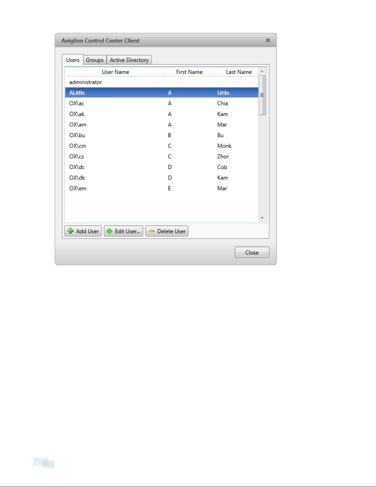
Figure 16: Users and Groups dialog box
3. When the Add User dialog box appears, complete the User Information area.
28 Adding a User
Page 29
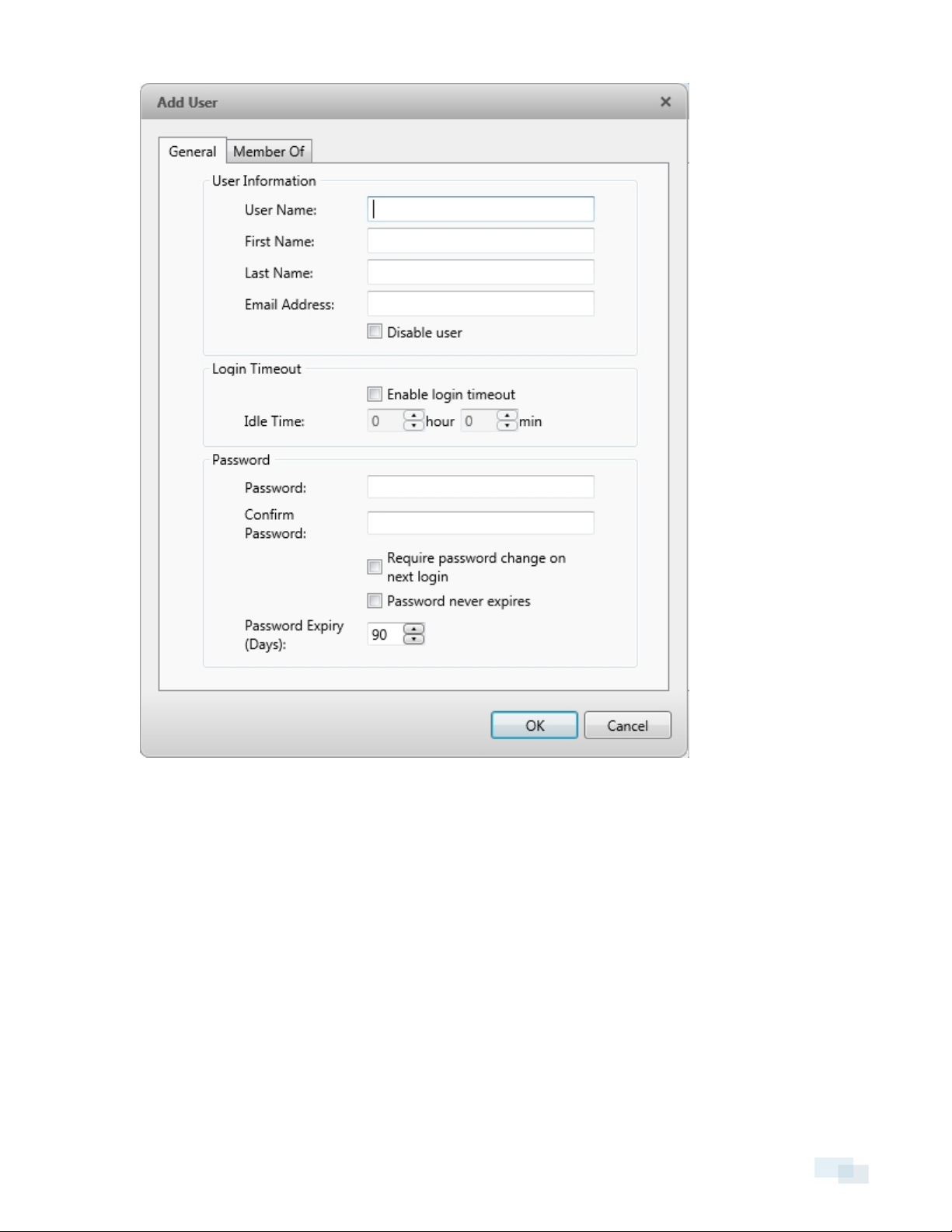
Figure 17: Add User dialog box, General tab
4. If you don’t want this user to be active yet, select the Disable user check box. Disabled users are in the
system but cannot access the Site.
5. In the Login Timeout area, select the Enable login timeout check box to limit the amount of time the user
can be logged in while the Client is idle.
6. In the Password area, complete the following fields:
l Password: enter a password for the user.
l Confirm Password: re-enter the password.
l Require password change on next login: select this check box if the user must replace the
password after the first login.
Adding a User 29
Page 30
l Password Expiry (Days): specify the number of days before the password must be changed.
l Password never expires: select thischeck box if the password never needs to be changed.
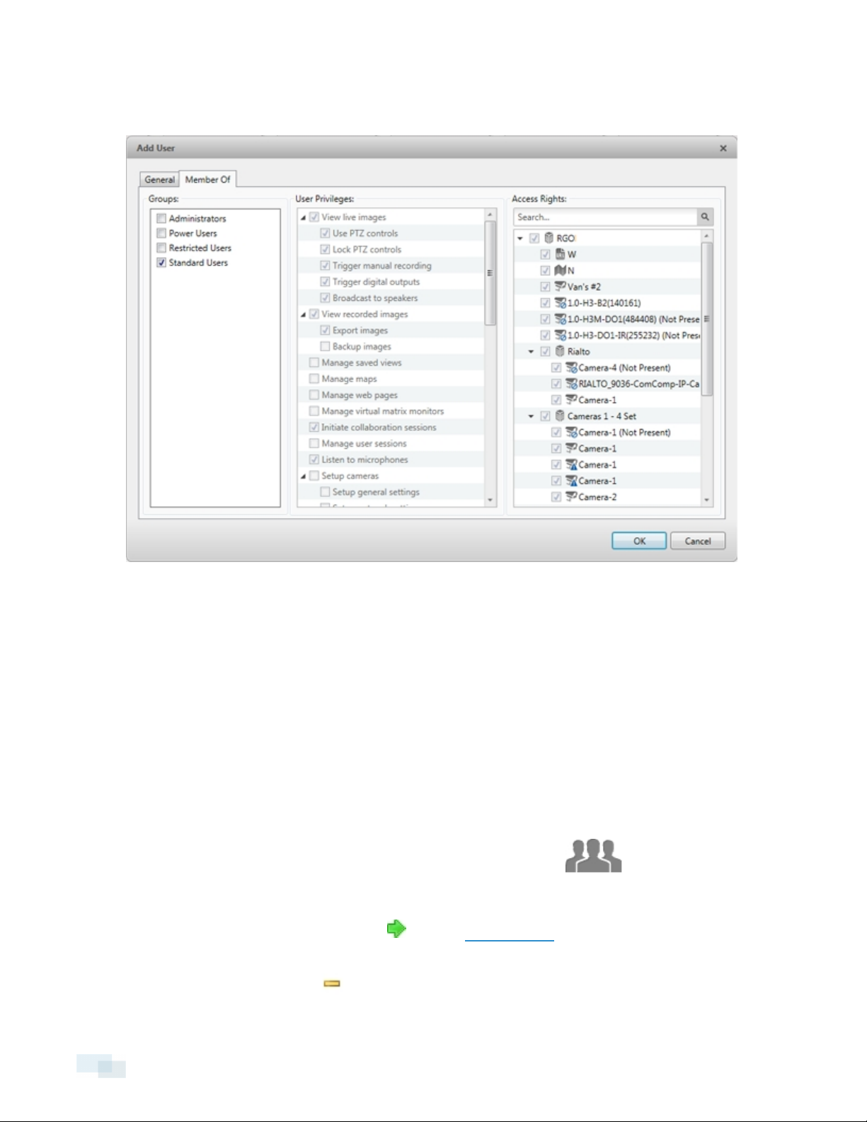
7.
Figure 18: Add User dialog box, Member Of tab
In the Member Of tab select the check box beside each access group the user belongs to.
The other two columns display the permissions linked to the selected group.
8. Click OK. The user is added to the Site.
Editing and Deleting a User
You can edit and delete users as needed.
NOTE: Be aware that you cannot edit or delete users that belong to the same ranked group as you or higher. This
also means that you cannot edit your own user account unless you are part of an Unranked group.
Tip: If a user has access to more than one Site, the changes to the user need to be made on each Site.
1.
In the Setup tab, select the Site whose user you want to edit, then click .
2. In the Users tab, select a user then perform one of the following:
l
To edit the user's information, click . Refer to Adding a User for details about the editable
options.
l
To delete the user, click .
30 Editing and Deleting a User
Page 31

Adding Groups
Groups define what features users have access to. Create new groups to change what users can access.
1.
In the Setup tab, select the Site to you want to add groups to, then click .
2.
Select the Groups tab and click .
Figure 19: Groups tab
3. Select an existing group to use as a template for your new group, then click OK.
Adding Groups 31
Page 32

Figure 20: Copy permissions from group: dialog box
4. In the Edit Group dialog box, complete the following:
Figure 21: Edit Group dialog box: Group tab
a. Give the new group a name.
b. Give the group a rank. Each rank is a number and is generally categorized into Global (100),
National (200), Regional (300), State (400) and Local (500). Unranked groups have access over all
ranks. By default, new groups are ranked below the group creator.
The higher the number, the lower the rank. For example, a group with a Global (100) rank can
control all the other ranked groups, but a group with a State (400) rank can only control Local (500)
groups and not Regional (300) groups.
32 Adding Groups
Page 33

You can also set a custom rank by entering a number in the Rank: field. A rank of 101-199 would be
considered part of the Global (100) category. For example, a group ranked 150 would be able to
control groups 151 and up, but would not be able to see or control group 149.
c. Select the Group Privileges: and Access Rights: for the group. Clear the check box of any feature
or camera you do not want the group to access.
5. Select the Members tab to add users to the group. If a user is added to the group through the Add User
dialog box, the user is automatically added to the group's Members list. See Adding a User for more
information.
Figure 22: Edit Grou p dialog box: Members tab
a.
Click .
b. Select the users that should be part of this new group. Only users that have been added to the Site
are displayed.
Adding Groups 33
Page 34

Figure 23: Select Users dialog box
c. Click Add. The users are added to the Members list.
6. Click OK to save the new group.
Editing and Deleting a Group
You can change the access permissions for a set of users by editing their access group.
1.
In the Setup tab, select the Site whose groups you want to edit, then click .
2. Select the Groups tab.
3. Select a group and do one of the following:
l
To edit the group, click . Refer to Adding Groups for details about the editable options.
l
To delete the group, click .
NOTE: Default groups cannot be deleted.
34 Editing and Deleting a Group
Page 35

Email Notifications
Use the Email Notifications dialog box to set up the Site to send email in response to specific events. You can
choose what events require email notifications and who receives the emails.
Setting Up the Email Server
To send email notifications, the Site must be given access to an email server.
1.
In the Setup tab, select the Site you want to send emails from, then click .
2. Select the Email Server tab.
Figure 24: Email Notification s dialog box: Email Server tab
3. In the Email Server Settings: area, complete the following:
a. Sender Name: enter a name to represent the Site in all email notifications.
b. Sender Email Address: enter an email address for the Site.
c. Subject Line: enter a subject line for all emails sent from the Site. The default subject is Avigilon
Control Center System Event.
d. SMTP Server: enter the SMTP server address used by the Site.
e. Port: enter the SMTP port.
Email Notifications 35
Page 36

f. Timeout (seconds): enter the maximum amount of time the server will try to send an email before it
quits.
4. (Optional) If the email server uses encryption, you can select the Use secure connection (TLS/SSL) check
box.
5. (Optional) If the email account has a username and password, select the Server requires authentication
check box.
a. Enter the User Name: and Password: for the email account.
6. Click OK.
Configuring Email Notifications
In the Email Notifications dialog box, you can create email notification groups to specify who will receive email
notifications when certain events occur.
NOTE: Some features are not displayedif the server does not have the required license, or if you do not have
the required user permissions.
1.
In the Setup tab, select the Site whose email notifications you want to configure, then click .
2. In the Email Notifications dialog box, make sure the Email Notifications tab is selected.
36 Configuring Email Notifications
Page 37

3.
Click .
Figure 25: Email Notifications dialog box
4. Enter an Email Group Name:.
5. In the Email Recipients: area, add all the user, group, and individual emails that are part of this email
group. Do any of the following:
l
Click to add a Site user or access group. In the dialog box, select all the required users and
groups then click OK.
l
Click to add individual emails. In the dialog box, enter the email address, then click OK.
Tip: Make sure the Site users in the Email Recipients: list have a valid email in their user account.
6.
Click to send a test email to everyone on the Email Recipients: list.
7. In the Email Trigger: area, select all the events that will trigger an email for this email group. Click the blue
underlined text to define the event requirements.
Configuring Email Notifications 37
Page 38

8. To attach a snapshot of the email notification event, select the Attach images from camera(s) linked to the
event check box.
NOTE: This option is disabled if Motion Detect is not selected because there are no images associated
with system events, digital inputs, or POS transaction exceptions.
9. In the Email Schedule: area, select a schedule for the email notification. See Scheduling Site Events for
more information.
10. To limit the number of emails sent, enter the minimum amount of time between each email in the Send
email at most every: field.
11. Click OK.
Editing and Deleting an Email Notification
You can edit or delete email notifications as needed.
1.
In the Setup tab, select the Site whose email notifications you want to edit, then click .
2. In the Email Notifications tab, do one of the following:
l To edit the email notification, select the Email Group from the Email Groups: list, then make the
required changes. Refer to Configuring Emails Notifications for details about the editable options.
l
To delete the email notification, select the Email Group from the Email Groups: list, then click .
Scheduling Site Events
Site events are actions that can affect the entire Site, like email notifications. When you configure a Site event,
you are given the option to assign a schedule to the event. Schedules control when events can occur — at
specific times during a day or only on specific days.
When you see the Schedule option while configuring an event, you can select an existing schedule or create a
new schedule.
Figure 26: Schedu le option
l To use a preconfigured schedule, select an option from the drop-down list. The default option is Always,
which allows the event to run constantly.
l
To change a schedule, select the schedule then click and select .
l
To delete a schedule, select the schedule then click and select .
l
To create a schedule, click then select . When you see the Edit… dialog box, complete the
following steps:
38 Editing and Deleting an Email Notification
Page 39

Figure 27: Edit… dialog box.
1. Give the new schedule a name.
2. Give the recurrence a name.
You can add multiple recurrences to create a detailed schedule. For example, you could create one
recurrence to cover every weekend, plus extra recurrences to cover public holidays.
l
To add a recurrence, click .
l
To delete a recurrence, select the recurrence then click .
3. In the Start: and End: fields, enter the time the recurrence will cover.
Be aware that if you enter an End: time that is earlier than the Start: time, the event will span two days. For
example, if the schedule is set to start at 12:00pm and end at 11:59am, the event is automatically enabled
from 12:00pm on day 1 and will end at 11:59am on day 2.
4. In the Start Date: field, enter when the recurrence should begin.
5. In the Recurrence pattern area, schedule how often the event will be enabled during this recurrence.
Option Description
The event is enabled during the same time every day.
Daily
l Select the number of days between each schedule recurrence.
Weekly The event is enabled during the same day and time every week.
Scheduling Site Events 39
Page 40

Option Description
l Select the day(s) of the week, then select the number of weeks between each
schedule recurrence.
The event is enabled during the same day and time every month.
Monthly
l Select the specific day or weekday, then select the number of months
between each schedule recurrence.
The event is enabled during the same day and time every year.
Yearly
l Select the specific day or weekday and month, then select the number of
years between each schedule recurrence.
6. Complete any other recurrences that have been added to the schedule.
7. Click OK to save the new schedule.
40 Scheduling Site Events
Page 41

Server Settings
Server settings are related to video recording. This includes configuring the recording schedule, data aging, and
bandwidth usage.
NOTE: Some features are not displayedif the server does not have the required license, or if you do not have
the required user permissions.
Server Name
Give the server a meaningful name so that it can be easily identified in the System Explorer. Otherwise, the
server uses the name that is assigned by Windows.
1.
In the Setup tab, select the server you want to edit, then click .
2. In the dialog box that appears, give the server a name.
Figure 28: Server Name dialog box
3. Click OK.
Recording Schedule
Use the Recording Schedule dialog box to set the recording schedule for cameras connected to the server. By
default, the server is set to record motion and configured events when they occur.
Once the recording schedule is set, video is recorded automatically.
Setting Up a Weekly Recording Schedule
You can set up a weekly recording schedule by applying templates to cameras for each day of the week.
1.
In the Setup tab, select the server you want to set up, then click .
2. In the Recording Schedule dialog box, select a template from the Templates: pane.
Server Settings 41
Page 42

3. In the Default Week area, click the days of the week this template applies to for each camera.
Figure 29: Recording Schedule dialog box: Default Week
4. Click OK.
Using Templates to Modify the Recording Schedule
The recording schedule is set by using templates that tell cameras when and what to record. For example, you
can create one recording schedule template for weekdays and another for weekends.
Adding a Template
NOTE: Some features are not displayedif the server does not have the required license, or if you do not have
the required user permissions.
1.
In the Setup tab, select the server you want to add a recording schedule to, then click .
2. In the Templates: pane, in the Recording Schedule dialog box, click Add Template
Figure 30: Recording Schedule dialog box
3. Enter a name for the New Template.
4. Click the Set Area button, then click or drag the cursor across the Recording Mode: timeline to set the
types of events that the cameras will record throughout the day. Individual rectangles on the Recording
Mode: timeline will be colored if they have been selected.
42 Using Templates toModify the Recording Schedule
Page 43

Record Mode Definition
Continuous Record video constantly.
Motion Only record video when motion is detected.
5. To disable recording in parts of the template, click the Clear Area button, then click or drag the cursor
across the timeline to remove the set recording areas.
6. If cameras are not recording in Continuous mode all day, you can set cameras to record reference
images between events in the recording schedule.
l Select the Record a reference image every: check box then set the time between each
reference image.
Editing and Deleting a Template
1.
In the Setup tab, select the server you want to edit, then click .
2. In the Recording Schedule dialog box, select a template from the Templates: pane and do one of the
following:
l To edit a template, modify the schedule.
l To rename a template, click Rename Template and enter a new name.
l To delete a template, click Delete Template.
3. Click OK to save your changes.
Recording and Bandwidth
While the Recording Schedule dialog box sets when and what cameras record, the Recording and Bandwidth
dialog box sets how long recorded video is stored.
In the Recording and Bandwidth dialog box, you can change the Data Aging settings and set the maximum
record time for each connected camera.
Editing and Deleting a Template 43
Page 44

1.
In the Setup tab, select the server you want to edit, then click .
Figure 31: Recording and Bandwidth dialog box
The Data Aging column shows an estimate of the recording time that is available at each image rate,
given the amount of space on the server.
l For JPEG2000 or JPEG compression cameras, Data Aging is available at three rates:
l Full Image Rate and Resolution keeps recordings at their original quality.
l Half Image Rate discards half of the recorded data to make room for new recordings.
l Quarter Image Rate keeps 1/4 of the original recorded data so that you can still see older
video.
l For H.264 cameras that support Data Aging, Data Aging is available at two rates:
l Full Image Rate and Resolution keeps the original high quality video and the secondary
stream of low resolution video.
l Low Resolution only keeps the secondary stream of low resolution video.
NOTE: Data Aging can only occur when the secondary stream is enabled.
l For H.264 cameras that do not support Data Aging, only the Full Image Rate and Resolution video is
kept.
2. In the Data Aging column, move the sliders to adjust the amount of time video is stored at each image
rate.
44 Recording and Bandwidth
Page 45

l To change the data aging settings for all linked cameras, move the slider for one linked camera
and all linked cameras will be updated.
l To change the data aging setting for one camera, break the camera's link to other cameras by
clicking the icon to the left of its name, then make your changes.
3. In the Max. Record Time, manually enter a maximum record time or select one of the options from the
drop-down list for each camera.
NOTE: If the time estimated in the Total Record Time column is shorter than what is set in the Max. Record
Time column, the camera's actual recording time will be shorter than the Max. Record Time .
4. Click OK.
Recording and Bandwidth 45
Page 46

Camera Settings
Camera settings are used to adjust video quality and set up devices that can be connected to cameras. These
settings include adjusting camera display quality, video compression, and image rate.
NOTE: Some features are not displayedif the server does not have the required license, or if you do not have
the required user permissions.
NOTE: The dialog box may appear differently depending on the camera. Options that are not supported by the
camera will be disabled or hidden.
General
Use the camera General dialog box to set the camera's identity and configure the camera's PTZ settings. You
can also reboot the camera through the General dialog box.
Setting the Camera's Identity
In a camera's General dialog box you can give the camera a name, describe the camera's location, and give the
camera a logical ID. The logical ID is needed to control the camera through keyboard and joystick commands.
NOTE: The dialog box may appear differently depending on the camera. Options that are not supported by the
camera will be disabled or hidden.
1.
In the Setup tab, select the camera you want to edit and click
2. In the Camera Name: field, give the camera a meaningful name to help you identify the camera. By
default, the camera model number is used as the camera's name.
3. In the Camera Location: field, describe the camera's location.
4. In the Logical ID: field, enter a unique number to allow the Client and integrations to identify this camera.
5. To disable the LEDs on the camera, select the Disable camera status LEDs. This may be required if the
camera is installed in a covert location.
6. If the camera has a motorized zoom and focus lens, the Enable PTZ controls check box will be displayed.
See Configuring PTZ for more information.
7. Click OK.
Configuring PTZ
Use the camera General dialog box to enable and configure the motorized pan, tilt, zoom (PTZ) devices that may
be connected to Avigilon™ cameras. PTZ devices are connected to Avigilon cameras through the RS-485 inputs.
Third-party PTZ camera controls cannot be configured through the Control Center software.
46 Camera Settings
Page 47

1.
In the Setup tab, select the camera you wish to configure and click . Click
2. In the PTZ area, select the Enable PTZ controls check box.
NOTE: If the following options are not displayed, the camera only has a motorized zoom and focus lens
that can be controlled through the PTZ Controls pane. Other PTZ controls will not be available.
3. In the Protocol: drop-down list, select the appropriate PTZ protocol. The available protocols include:
l AD Sensormatic
l AXSYS
l AXSYS DCU
l Ernitec ERNA
l Honeywell Diamond
l Kalatel ASCII
l Pelco D
l Pelco P
l TEB Ligne
l Videotec MACRO
l Videotec Legacy
l Vicon extended
l Vicon normal
l JVC JCBP
4. Enter the Dip Switch Address:, Baud Rate:, and Parity: for the PTZ device.
5. Click OK.
Once PTZ has been configured, you can use the camera's PTZ Controls while you watch the camera's live video
stream. See Controlling PTZ Cameras for more information.
Rebooting the Camera
You can restart all Avigilon cameras through the camera's General dialog box. This feature is not available for
third party cameras.
1.
In the Setup tab, select a camera and click .
2. Click Reboot Camera....
The camera will disconnect from the Avigilon Control Center and shut down. When the camera starts up again,
the camera should automatically reconnect with the Avigilon Control Center.
Rebooting the Camera 47
Page 48

Network
Use the camera Network dialog box to change how a camera connects to the server network.
NOTE: Some features are not displayedif the server does not have the required license, or if you do not have
the required user permissions.
1.
In the Setup tab, select a camera and click .
2. In the Network dialog box, select how the camera obtains an IP address:
Figure 32: Network dialog box
l Obtain an IP address automatically: select this option for the camera to connect to the network
through an automatically assigned IP address.
The camera will attempt to obtain an address from a DHCP server. If this fails, the camera will obtain
an address through Zero Configuration Networking (Zeroconf) and select an address in the
169.254.0.0/16 subnet.
l Use the following IP address: select this option to manually assign a static IP address to the
camera.
Enter the IP Address:, Subnet Mask:, and Gateway: you want the camera to use.
3. Select the Control Port: for connecting to the camera. This port is also used for manually discovering the
camera on the network.
4. Click OK.
48 Network
Page 49

Image and Display
Use the Image and Display dialog box to control a camera’s display settings for live and recorded video.
NOTE: The dialog box may appear differently depending on the camera. Options that are not supported by the
camera will be disabled or hidden.
Changing Image and Display Settings
NOTE: The dialog box may appear differently depending on the camera. Options that are not supported by the
camera will be disabled or hidden.
1.
In the Setup tab, select the camera you want to edit and click .
2. In the Image and Display dialog box, make the required changes to adjust the camera's image settings. A
preview of your changes is displayed in the image panel.
Tip: Use the Maximum Exposure:, Maximum Gain:, and Priority: options to control low light behavior.
Figure 33: Image and Display dialog box
Option Description
You can allow the camera to control the exposure by selecting Automatic, or
Exposure:
Iris:
Image and Display 49
you can set a specific exposure rate.
NOTE: Increasing the manual exposure time may affect the image rate.
You can allow the camera to control the iris by selecting Automatic, or you
Page 50

Option Description
can manually set it to Open or Closed.
IR Cut Filter:
Flicker Control:
Backlight Compensation:
Enable Wide Dynamic
Range
Maximum Exposure:
Maximum Gain:
You can allow the camera to control the infrared cut filter by selecting IR Cut
Filter:, or set the camera to Color or Monochrome mode.
If your video image flickers because of the fluorescent lights around the
camera, you can reduce the effects of the flicker by setting the Flicker
Control: to the same frequency as your lights. Generally, Europe is 50 Hz and
North America is 60 Hz.
If your scene has areas of intense light that cause the overall image to be too
dark, move the Backlight Compensation: slider until you achieve a well
exposed image.
Select this box to enable automatic color adjustments through Wide Dynamic
Range (WDR). This allows the camera to adjust the video image to
accommodate scenes where bright light and dark shadow are clearly visible.
You can limit the automatic exposure setting by selecting a Maximum
Exposure: level.
By setting a Maximum Exposure : level for low light situations, you can control
the camera's exposure time to let in the maximum amount of light without
creating blurry images.
You can limit the automatic gain setting by selecting a Maximum Gain: level.
By setting a Maximum Gain: level for low light situations, you can maximize the
detail of an image without creating excessive noise in the images.
Priority:
Saturation:
Sharpening:
Image Rotation:
White Balance
You can select Image Rate or Exposure as the priority.
When set to Image Rate, the camera will maintain the set image rate as the
priority, and will not adjust the exposure beyond what can be recorded for the
set image rate.
When set to Exposure, the camera will maintain the exposure setting as the
priority, and will override the set image rate to achieve the best image
possible.
You can adjust the video's color intensity by moving the Saturation: slider until
the video image meets your requirements.
You can adjust the video sharpness to make the edges of objects more
visible. Move the Sharpening: slider until the video image meets your
requirements.
You can change the rotation of captured video. You can rotate the video 90,
180, or 270 degrees clockwise.
You can control white balance settings to adjust for differences in light.
You can allow the camera to control the white balance by selecting Automatic
white balance, or select Custom white balance and manually set the Red: and
Blue: settings.
50 Changing Image and Display Settings
Page 51

3. To focus the camera, see Zooming and Focusing the Camera Lens.
4. Click Apply to Cameras... to apply the same settings to other cameras of the same model.
5. Click OK.
Zooming and Focusing the Camera Lens
If the camera has remote zoom and focus capabilities, you can control the camera's zoom and focus through the
Image and Display dialog box.
1.
In the Setup tab, select the camera you want to edit and click .
2. If the camera has a built-in auto-focus feature, you can choose one of the following:
l Continuous Focus: the camera will automatically focus itself whenever the scene changes. Skip
the following steps.
l Manual Focus: you can manually focus the camera through the Focus: buttons. Once the focus is
manually set, it will not change.
3. While you watch the preview in the image panel, complete the following steps to zoom and focus the
camera:
a. Use the Zoom: buttons to zoom in to the distance you want to focus.
4. In the Iris: drop-down list, select Open. When the iris is fully open, the camera's depth of field is the
shortest.
5. Use the Focus: buttons until the image becomes clear.
Focus Buttons
Button Description
The camera will automatically focus one time.
The camera will focus as close to zero as possible.
Large step toward zero.
Small step toward zero.
Small step toward infinity.
Large step toward infinity.
Zooming and Focusing the Camera Lens 51
Page 52

Button Description
Infinity.
6. Click Apply to Cameras... to apply the same settings to other cameras of the same model.
7. Click OK.
Dewarping an Immervision Panomorph Lens
If your camera uses an Immervision Panomorph lens, you may choose to dewarp the image through the Avigilon
Control Center software.
1.
In the Setup tab, choose an Immervision Panomorph lens camera and click .
2. In the Image and Display dialog box, select the Lens Type : used by the camera.
If the Lens Type list is empty, contact Avigilon Technical Support and request that support for your
camera and lens model be added to the application.
Figure 34: Image and Display dialog box for fisheye lens configuration
3. In the View Perspective: drop-down list, select one of the following options:
l Floor: select this option if the camera is installed to look up.
l Ceiling: select this option if the camera is installed to look down.
52 Dewarping an I mmervision Panomorph Lens
Page 53

l Wall: select this option if the camera is installed to look at the horizon.
4. Click OK.
The system dewarps the lens image based on the way it is installed. You will be able to control how video is
display in an image panel through the PTZ controls.
Compression and Image Rate
Use the camera Compression and Image Rate dialog box to modify the camera's frame rate and image quality
settings for sending image data over the network.
NOTE: The dialog box may appear differently depending on the camera. Options that are not supported by the
camera will be disabled or hidden.
For more information about the supported compression technologies, see the Understanding Compression
Technologies for HD and Megapixel Surveillance white paper on the Avigilon website.
1.
In the Setup tab, select a camera and click .
Figure 35: Compression and Image Rate dialog box.
The Bandwidth: area gives an estimate of the bandwidth used by the camera with the current settings.
Adjust the settings as required.
NOTE: For cameras capable of maintaining multiple streams, the settings in this dialog box only affect the
primary stream.
2. In the Format: drop-down list, select the preferred streaming format.
Compression and Image Rate 53
Page 54

3. In the Image Rate: bar, move the slider to select the number of images per second (ips) you want the
camera to stream over the network.
For H.264 cameras and encoders, the image rate setting must be divisible by the maximum image rate. If
you set the slider between two image rate settings, the application will round to the closest whole
number.
4. In the Image Quality: drop-down list, select an image quality setting. An image quality setting of 1 will
produce the highest quality video and require the most bandwidth. The default setting is 6.
5. In the Max Bit Rate: drop-down list, select the maximum bandwidth the camera can use in kilobits per
second (kbps).
6. In the Resolution: drop-down list, select the preferred image resolution.
7. In the Keyframe Interval: drop-down list, enter the preferred number of frames between each keyframe.
It is recommended that you have at least one keyframe per second. So, if the image rate is set to 30 ips,
you should enter 30 for the Keyframe Interval: setting.
8. If your camera supports multiple video streams, you can select the Enable secondary stream check box.
When enabled, the secondary stream is a lower resolution video stream that is used by Avigilon's HDSM
feature to maximize bandwidth and storage efficiencies.
9. Click Apply to Cameras... to apply the same settings to other cameras of the same model.
10. Click OK.
Image Dimensions
Use the Image Dimensions dialog box to set the image dimensions for the camera. You can crop the video
image to help reduce bandwidth and increase the maximum image rate.
1.
In the Setup tab, select the camera you want to edit and click .
2. In the Image Dimensions dialog box, adjust the image dimensions by doing one of the following:
l Drag the edges of the image until the video is cropped to fit your requirements.
l Change the values for the Top:, Left:, Width:, and Height: fields.
54 Image Dimensions
Page 55

Figure 36: Image Dimension s dialog box
3. Click OK.
Motion Detection
In the Motion Detection dialog box you can define specific motion detection areas and configure the camera's
sensitivity and threshold for motion.
Selecting a Motion Detection Area
In the Motion Detection dialog box, you can set the green motion detection areas in the camera's field of view.
Motion detection is ignored in the areas not highlighted in green.
1.
In the Setup tab, select the camera you want to edit and click .
2. In the Motion Detection dialog box, use the tools above the image panel to define the green motion
detection area:
l
can draw multiple rectangles to create your motion detection area.
Motion Detection 55
: Click this button then draw green rectangles to define the motion detection areas. You
Page 56

l
: Click this button and draw rectangles to erase sections from the motion detection area.
l
: Click this button and manually draw motion detection areas with your mouse. This tool
allows you to be very specific and highlight unusual shapes.
l
l
: Click this button to highlight the entire image panel for motion detection.
:Click this button to clear the image panel of all motion detection areas.
Tip: Avoid areas with continuous motion, like a TV or computer monitor, so that the camera is not
constantly detecting unimportant motion events.
Figure 37: Motion Detection dialog box
3. Click OK.
To define the sensitivity and threshold of the motion detection area, see Controlling Motion Sensitivity and
Threshold.
Controlling Motion Sensitivity and Threshold
In the Motion Detection dialog box, you can control the camera's sensitivity and threshold for motion. You can
also define how long video is recorded before and after each motion event.
56 Controlling Motion Sensitivity and Threshold
Page 57

1.
In the Setup tab, select the camera you want to edit and click .
Figure 38: Motion Detection dialog box
2. Move the Sensitivity: slider to adjust how much each pixel must change before it is considered in motion.
When the sensitivity is High, even small movements are detected - like dust floating immediately before
the camera lens.
3. Move the Threshold: slider to adjust how many pixels must change before the image is considered to
have motion.
When the threshold is High, only large motions are detected - like a truck driving across the scene.
Tip: The Motion indicator above the Threshold: slider will move to indicate how much motion is occurring
in the current scene. Only when the motion indicator moves to the right of the Threshold: marker will the
camera detect the motion.
4. In the Pre-Motion Record Time: and Post-Motion Record Time: fields, specify how long video is recorded
before and after the motion event.
5. Click OK.
Privacy Zones
You can set privacy zones in the camera's field of view to block out areas that you do not want to see or record,
like bathroom entrances and other private areas.
Privacy Zones 57
Page 58

Adding a Privacy Zone
NOTE: You can add up to 4 privacy zones per camera.
1.
In the Setup tab, select the camera you want to edit and click .
2.
In the Privacy Zones dialog box, click and a green box will appear on the image panel.
Figure 39: Privacy Zones dialog box
3. Move and resize the green box until it covers the area you want to block out.
4. Click OK.
Editing and Deleting a Privacy Zone
1.
In the Setup tab, select the camera you want to edit and click .
2. In the Privacy Zones dialog box, select a privacy zone from the Privacy Zones: list and do one of the
following:
l To edit the privacy zone, adjust the green box in the image.
l
To delete the privacy zone, click .
3. Click OK to save your changes.
58 Adding a Privacy Zone
Page 59

Manual Recording
When you trigger manual recording in an image panel, you are telling the camera to record video outside of its
recording schedule. Manual recording continues until it is stopped, or until the maximum manual recording time
is reached.
To set the maximum manual recording time, follow these steps:
1.
In the Setup tab, select the camera you want to edit and click .
Figure 40: Manual Recording dialog box
2. Specify the following:
l Manual Recording Duration: enter how long the camera should record if recording is not manually
stopped.
l Pre-Trigger Record Time: enter the amount of time video is recorded before manual recording is
activated.
3. Click Apply to Cameras... to apply the same settings to other cameras of the same model.
4. Click OK.
For more information on manually recording video, see Triggering Manual Recording.
Manual Recording 59
Page 60

Client Settings
Client Settings... are used to set your preferences for your local copy of the Client software. This includes saving
your password, setting the language, saving your last window layout, configuring your joystick, and manually
adding and removing Sites.
General Settings
Use the General settings to set your local Client preferences. Any changes you make will only affect this copy of
the Client software.
NOTE: Some features are not displayedif the server does not have the required license, or if you do not have
the required user permissions.
1.
In the top-right corner of the Client, select > Client Settings....
2. In the General tab, make any required changes:
60 Client Settings
Page 61

Figure 41: Client Settings... dialog box
l Save/restore window layout: Select this check box if you want the Client to remember your layout
preferences.
l Automatically launch full screen: Select this check box if you want the Client to automatically
launch in full screen mode each time it starts.
l Display Notifications: Select this check box if you want the Client to display system messages.
System messages are listed in the red box at the top-right corner of the Client - click the red box to
see the messages. System messages notify you of Site events, system events and possible
device connection issues.
If this check box is cleared, all system messages are hidden.
l Cycle dwell time: Enter the number of seconds the Client waits before it cycles to a different View
tab. See Cycling Through Views for more information.
l Language: Select a language from the drop-down list to change the Client language. Select
General Settings 61
Page 62

Windows Default for the Client to use the same language as the operating system.
l Automatically log in to sites: Select this check box to automatically log in to all Sites you can
access. Select the type of login you use:
l Select Using Windows Authentication if you use your Windows login to access Sites.
l Select Using saved user name and password: if you use your AvigilonControl Center
username and password.
l In the Maximum Incoming Client Bandwidth: area, you can set how much bandwidth is received by
the client. This includes video streaming.
You can select Unlimited or Other:, and specify the maximum bandwidth allowance in kilobits per
second (kbit/s).
3. Click OK to save your changes.
Joystick Settings
There are two types of joysticks supported by the Client: standard Microsoft DirectX USB joysticks and the
Avigilon USB Professional Joystick Keyboard.
Access the Joystick settings to install the required drivers and configure your joystick options.
Configuring an Avigilon™ USB Professional Joystick Keyboard For Left-Hand Use
The Avigilon USBProfessional Joystick Keyboard is a USB add-on that contains a joystick for controlling zooming
and panning within image panels, a jog shuttle for controlling the Timeline, and a keypad programmed with the
Client's keyboard commands. Refer to Keyboard Commands for the keypad commands that control the Client.
By default, the keyboard is installed in right-hand mode. Change the Joystick settings to configure it for left-hand
mode.
1. Connect the keyboard.
2.
In the top-right corner of the Client, select > Client Settings... > Joystick.
If the keyboard is not automatically detected, an error message will appear. Click Scan for Joysticks....
Otherwise, the following option is displayed.
62 JoystickSettings
Page 63

Figure 42: Joystick dialog box
3. Select the Enable left-hand mode check box.
4. Click OK. The keyboard is now configured for left-hand mode.
5. Rotate the keyboard until the joystick is on the left and the jog shuttle is on the right. Reinstall the keypad
cover with the View button labels at the top.
For more information about the Avigilon USB Professional Joystick Keyboard, see the installation guide included
with the device.
Configuring a Standard USB Joystick
Use the Joystick settings to configure the buttons used in your standard Microsoft DirectX USB joystick.
1.
Connect the joystick. In the top-right corner of the Client, select > Client Settings > Joystick.
2. If the joystick is not automatically detected, an error message will appear. Click Scan for Joysticks....
Otherwise, the following options are displayed:
Configuring a Standard USB Joystick 63
Page 64

Figure 43: Joystick dialog box
3. Choose an action for each button on the joystick:
a. Press a button on the joystick to highlight its label in the dialog box.
b. Select an action for the button from the drop-down list.
Options include ways to control recorded video, Views, image panels, instant replay, audio,
snapshots and PTZ.
c. Repeat this procedure for each button on the joystick.
4. Click OK.
Video Display Settings
You can adjust the Client Display settings to improve how video is displayed on your monitor.
NOTE: Some features are not displayedif the server does not have the required license, or if you do not have
the required user permissions.
64 VideoDisplay Settings
Page 65

1.
In the top-right corner of the Client, select > Client Settings... > Display.
Figure 44: Display Se ttings tab
2. Follow any of the following procedures to adjust how video is displayed in image panels.
Displaying Analog Video in Deinterlaced Mode
Select the Display Deinterlaced Images check box if the analog video you are watching is showing interfacing
artifacts. This setting will help improve video image and smooth out some of the artifacts.
Displaying Image Overlays
Select any of the Image Overlays: options to set the type of information that is displayed over video.
Overlay Description
Camera Name Displays the name assigned to the camera.
Displaying AnalogVideo in Deinterlaced Mode 65
Page 66

Overlay Description
Camera Location Displays the location assigned to the camera.
Playback Timestamp (Recorded video only) Displays the exposure timestamp for the video.
Live Timestamp (Live video only) Displays the current system date and time to the millisecond.
(Live video only) Displays the recording status of a camera.
The recording status is indicated by the round icon on the top left corner of the image
panel. The color of the icon shows the camera's recording status.
Record Indicator
Motion Activity Highlights motion in red.
Video Analytics Activity
l
: recording triggered by a motion event
l
: recording
l
: not recording. Click this icon at any time to begin manual recording.
Bounding boxes outline objects detected in the video. The color of the bounding box
identifies the object type:
l Red - a person
l Blue - a vehicle
l Yellow - a suspicious object
The Video Analytics Activity overlay is only activated for video from cameras that are
connected to a Rialto device.
NOTE: If both the Motion Activity overlay and the Video Analytics Activity overlay are
enabled, for cameras connected to a Rialto device the system will only display
bounding boxes, and will not display the red motion activity overlay.
Changing Display Quality
If your computer does not have enough network bandwidth or processing power, you may not be able to watch
video at its full image rate and quality. You can configure the image panels to display video in high quality and
low frame rate, or low quality and high frame rate.
Select a higher display quality setting if you need to see specific details or faces in the scene. Select a lower
display quality setting if it's more important to see moving events as they occur.
The Change Display Quality: settings only affect the image panel display and do not affect the actual video
quality or image rate between the camera and the server. Therefore, you can review recorded footage later to
confirm what you saw in the image panel.
In the Change Display Quality: area, select one of the following options:
l Maximum: displays video at full resolution with the lowest image rate.
l High (Default): displays video at 1/4 resolution.
l Medium: displays video at 1/16 resolution.
l Low: displays video at 1/64 resolution with the highest image rate.
66 Changing Display Quality
Page 67

What are Views?
A View tab is where you watch camera video. Inside the View tab is a set of image panels that allows you to
organize how video is displayed.
You can arrange image panels into different layouts to take advantage of different camera angles and save
View layouts that you like.
See Monitoring Video for more information on controlling live and recorded video.
Adding and Removing a View
View tabs allow you to customize how you monitor video. You can open a new View in the current window or
open a View in a new window to make use of multiple monitors. Views can also be removed as required.
To... Do this...
Open a new View tab
Close a View tab
Open a new window
Close a window
Click > .
On the View tab, click .
Select > New Window
A new window appears. You can now position this window to make use
of multiple monitors.
In the top-right corner of the window, click .
NOTE: If you see a confirmation dialog box, it is because there is only
one window open and closing this window will also close the
application.
View Layouts
You can organize how video is displayed through View layouts. You can choose to display video in 1 - 64 image
panels. You can also customize the shape of image panels to accommodate cameras that are installed vertically
to capture long hallways.
There are 10 pre-configured layouts that you can edit to fit your needs.
Selecting a Layout for a View
You can organize how video is displayed by selecting a View layout. The figure below shows the default View
layouts.
What are Views? 67
Page 68

l
On the toolbar, select , then select one of the following layout options.
Figure 45: Layouts in the toolbar
Editing a View Layout
If the default View layouts do not fit your surveillance requirements, you can customize a View layout.
68 Editing a View Layout
Page 69

1.
On the toolbar, select >Edit Layouts....
Figure 46: Layouts in the toolbar
2. In the Edit Layouts dialog box, select the layout you want to change.
3. Enter the number of Columns: and Rows: you want in your layout.
Editing a View Layout 69
Page 70

4. In the layout diagram, do any of the following to further customize the layout.
Figure 47: Edit Layouts dialog box
l To create a larger image panel, select a gray line to delete the border between two image panels.
When a line is highlighted in red, the line can be deleted.
l To restore an image panel, select a dotted line to divide a larger image panel into two. When a
dotted line is highlighted in green, the line can be restored.
l To restore all default View layouts, click Restore Defaults. All custom layouts in the Layouts: list will
be replaced.
NOTE: You can only add or subtract lines to create a rectangular shape.
5. Click OK to save your changes. The previous View layout has been replaced with your customized layout.
Tip: The keyboard commands used to access View layouts are linked to the layout's position in the Layouts: list.
For example, if your custom layout is placed at the top of the Layouts: list (layout 1), you can press Alt + 1 to use
that layout.
Making a View Full Screen
You can maximize a View to fill an entire monitor screen.
70 Making a View Full Screen
Page 71

l
On the toolbar, click .
Ending Full Screen Mode
l
While the View is in full screen mode, click .
Cycling Through Views
If you have multiple Views open, you can cycle through the View tabs by displaying each one for a few seconds.
This is useful when monitoring a large number of cameras.
l
To activate the Cycle Views feature, click .
To change the amount of time each View is displayed for, change the Cycle dwell time: setting. See General
Settings for more information.
Ending Full Screen Mode 71
Page 72

Monitoring Video
Inside a View tab, you can monitor and control video from multiple cameras. Once you open a camera in a View
tab, you can control the camera's live and recorded video stream. You also have access to the camera's PTZ
controls and other playback settings.
To organize how video is displayed in the View tab, see What are Views?.
NOTE: Some features are not displayedif the server does not have the required license, or if you do not have
the required user permissions.
Zooming and Panning in a Video
Use the zoom and pan tools to focus on specific areas in the live or recorded video stream.
Using the Zoom Tools
There are two ways to digitally zoom in and zoom out of a video image:
l Move your mouse over the video image, then rotate your mouse wheel forward and backward.
l
On the toolbar, select or , then click the image panel until you reach the desired zoom depth.
Using the Pan Tools
There are two ways to pan through the video image:
l Right-click and drag inside an image panel
l
On the toolbar, select , then left-click and drag the video image in any direction inside the image
panel.
Maximizing and Restoring an Image Panel
You can maximize an image panel to enlarge the video display.
Maximizing an Image Panel
Do one of the following:
l Right-click an image panel and select Maximize.
l
Inside the image panel, click .
l Double-click the image panel.
Restoring an Image Panel
In a maximized image panel, do one of the following:
72 Monitoring Video
Page 73

l Right-click the maximized image panel and select Restore Down.
l
Inside the image panel, click .
l Double-click the image panel.
Making Image Panel Display Adjustments
You can change the image panel display settings to bring out video details that are hard to see with the image
panel's default settings.
1. Right-click an image panel and select Display Adjustments....
Figure 48: Display Adjustments... panel
The Display Adjustments... settings are displayed in a floating pane immediately beside the image panel.
2. Move the sliders to adjust the Gamma:, Black Level: and White Level:.
The image panel displays a preview of your changes.
3. Click Restore Defaults to clear your changes.
Controlling Live Video
In this section are features that are only available while monitoring live video.
Using Instant Replay
To review an event that just occurred, you can immediately access recently recorded video through the instant
replay feature.
Making Image PanelDisplay Adjustments 73
Page 74

l Right-click the image panel and select one of the instant replay options:
l Replay - 30 Seconds
l Replay - 60 Seconds
l Replay - 90 Seconds
The image panel immediately plays back the camera's most recently recorded video.
Triggering Manual Recording
Cameras are set to follow a recording schedule. If an event occurs outside the camera's recording schedule, you
can click the record indicator icon to force the camera to record the event. See Recording Schedule for more
information about recording schedules.
The Record Indicator overlay must be enabled to use manual recording. See Video Display Settings for more
information.
Camera Recording States
Recording Recording triggered by an event Not recording
Starting and Stopping Manual Recording
In an image panel that is displaying video, do either of the following:
l
In the top-left corner of the image panel, click to start manual recording.
The recording indicator is highlighted in blue to show that the camera is recording. Manual recording
continues until it is stopped or until the maximum manual recording time is reached.
l
Click to manually stop video recording.
The maximum manual recording time is configured in the Manual Recording dialog box. See Manual Recording
for more information.
PTZ Cameras
PTZ cameras can be controlled through the image panel on-screen controls or by using the tools in the PTZ
Controls pane.
Some tools and features may not be displayed if they are not supported by your camera.
Controlling PTZ Cameras
Pan, Tilt, Zoom (PTZ) controls allow you to control cameras with PTZ features. You can control a PTZ camera by
using the on-screen controls or by using the tools in the PTZ Controls pane.
See Keyboard Commands for other ways to use the PTZ controls.
74 Triggering Manual Recording
Page 75

1.
In the toolbar, click . PTZ controls are now enabled in image panels that are displaying PTZ video.
2.
In the image panel, click .
The PTZ Controls are displayed in a floating pane immediately beside the image panel.
NOTE: The controls may appear differently depending on the camera. Some options are disabled or
hidden if they are not supported by the camera.
Figure 49: PTZ Controls
3. To pan or tilt, do one of the following:
l In the image panel, drag your mouse from the center to move the camera in that direction. The
farther the cursor is from the center of the image panel, the faster the camera will move.
l If the camera supports Click to Center, click anywhere on the image panel to center the camera to
that point.
Figure 50: PTZ On-screen controls
Controlling PTZCamer as 75
Page 76

4. Use the other PTZ controls to perform any of the following:
To... Do this...
l
Click to zoom in.
l
Click to zoom out.
l Click the image panel and use the mouse scroll wheel
Zoom
to zoom in and out.
l If the camera supports Drag to Zoom, click and drag to
create a green box to define the area you want to
zoom in and see.
l Right-click the image panel and select Zoom Out Full.
l
Click to close the iris.
Control the iris
l
Click to open the iris.
l
Click to focus near the camera.
Control the focus
l
Click to focus far from the camera.
1. Move the camera's field of view into position.
Program a PTZ preset
Activate a PTZ preset
Return to the Home preset position
Program a PTZ pattern
Activate a PTZ pattern
2. In the Presets drop-down list, select a number then
click .
3. In the dialog box, enter a name for the preset.
4. Select the Set as home preset check box if you want
this to be the camera's Home preset.
5. Click OK.
Select a preset then click .
If the PTZ camera supports a Home preset position, click
to return the camera to its Home position.
1. In the PTZ Controls pane, select a pattern number and
click .
2. Use the PTZ controls to move the camera and create
the pattern.
3.
Click to stop recording the pattern.
In the PTZ Controls pane, select a pattern number and click
.
The pattern will repeat until the pattern is stopped or another
pattern is run.
Program a PTZ tour See Programming PTZ Tours
Activate a PTZ tour
76 Controlling PTZCameras
In the PTZ Controls pane, select a tour number and click .
Page 77

To... Do this...
Activate an auxiliary command
Display the PTZ camera on-screen menu
Lock the PTZ controls
The tour will repeat until stopped or until other PTZ controls
are used.
1.
Select an aux command number and click .
2.
Click to turn off the auxiliary output.
1.
Click .
2. To move through the menu options, click any of the
following:
l
Click to move down the options.
l
Click to move up the options.
l
Click to confirm your selection.
l
Click to cancel your selection.
Click .
Other users will be unable to use the PTZ controls for this
camera until you unlock the controls or log out.
Programming PTZ Tours
If the PTZ camera supports guard tours, the tours can be programmed through the PTZ controls pane. Tours
allow the PTZ camera to automatically move between a series of preset positions, and can be set to pause at
each preset for a specific amount of time for video monitoring.
1. Create all the PTZ presets you need for this tour.
2.
In the PTZ Controls pane, select a tour number then click . The Edit PTZ Tour dialog box is displayed.
Programming PTZTours 77
Page 78

Figure 51: Edit PTZ Tour dialog box
3. In the Edit PTZ Tour dialog box, give the tour a name.
4. In the Tour Pause Duration: field, enter the amount of time before a tour repeats. Tours repeat until
manually stopped, or until other PTZ controls are used.
5. In the Tour Mode: drop-down list, select one of the following:
l Sequential: the PTZ camera will go to each preset in the set order.
l Random: the PTZ camera will go to each preset in random order.
6. Select the Set as default tour check box if you want this tour to run automatically.
l The Default Tour Idle Start Time: field is now enabled. Enter the amount of time the PTZ camera
must be idle before this tour automatically starts.
7.
To add a preset to the list, click .
a. In the Preset column, select a preset from the drop-down list.
b. In the Move Speed column, enter how fast you want the PTZ camera to move to this preset. The
78 Programming PTZ Tours
Page 79

higher the %, the faster the camera moves.
c. In the View Time column, enter the amount of time you want the PTZ camera to stay at this preset
position. The view time is 10 seconds by default.
d. Repeat step 7 until all the presets for this tour have been added.
8.
To remove a preset, select the preset then click .
9.
To re-order a preset, select the preset then click or . The preset order only affects tours that use
Sequential mode.
10. Click OK to save the tour.
Controlling Recorded Video
In this section are features that are only available while monitoring recorded video.
Playing Back Recorded Video
The Timeline displays when video was recorded and lets you control video playback.
The colored bars on the Timeline show the camera's recording history:
l A red bar shows the camera has recorded a motion event.
l A blue bar shows the camera has recorded video.
l White areas show periods of time during which the camera has not recorded any video.
l An yellow bar is a bookmark in the camera's recording history.
See Bookmarking Recorded Video for more information about bookmarks.
Figure 52: Playback controls on the Timeline
To... Do this...
Select a playback
time
l Click the dark gray date display and select a specific date and time.
l Click a point on the Timeline.
Click .
Start playback
Controlling Recorded Video 79
l
Click to fast forward. Tap the arrow again to increase the playback speed.
l
Click to rewind. Tap the arrow again to increase the playback speed.
Page 80

To... Do this...
You can play the video up to eight times the original speed.
Click .
Stop playback
Jump forward or
backward on the
Timeline
Zoom in or out of the
Timeline
Center the Timeline
on the time marker
Pan the Timeline
l
Click to step forward one frame.
l
Click to step backward one frame.
On the Timeline, click or to move to set points on the
Timeline.
l Move the slider on the bottom left to zoom in or out
on the Timeline.
l Place your mouse over the Timeline and use the
scroll wheel to zoom in or out on the Timeline.
You can zoom in to a quarter of a second, and zoom out to
see years if recorded video exists.
Right-click the Timeline, and select Center on Marker.
l Click and drag the time marker through the
Timeline.
l Move the horizontal scroll bar under theTimeline.
l Right-click and drag the Timeline.
Synchronizing Recorded Video Playback
Synchronizing recorded video playback allows you to synchronize Timelines across multiple View, Alarm, and
Search tabs while they are in recorded mode.
Synchronized recorded video playback is disabled by default. Once it is enabled, it will remain enabled until it is
manually disabled.
NOTE: Tabs can only be synchronized to one time. You cannot synchronize groups of tabs to separate times.
Enabling Synchronized Recorded Video Playback
l
To enable synchronized recorded video playback in all new View tabs, select > Client Settings... >
General > Synchronize recorded video playback.
Timelines will be automatically centered on the current time.
80 Synchronizing Recorded Video Playback
Page 81

Enabling synchronized recorded video playback in the Client Settings... dialog box will not synchronize
the Timelines of previously opened tabs. It will only synchronize new tabs that are opened after enabling
synchronized recorded video playback. Previously opened tabs need to be synchronized individually.
l To synchronize playback between specific or previously opened tabs, click the gray button on the
tab Timeline.
Disabling Synchronized Recorded Video Playback
l Synchronized recorded video playback can be disabled for all new tabs by clearing the Synchronize
recorded video playback check box in the Client Settings... dialog box. Previously synchronized tabs will
remain synchronized.
l Synchronized recorded video playback can also be disabled in individual tabs.
On a synchronized Timeline, click the blue button. The button will turn gray to show that it is no longer
synchronized. The Timeline will stay where it is, but will no longer be synchronized with other Timelines.
Bookmarking Recorded Video
You can add bookmarks to recorded video to help you find and review an event later. Bookmarked video can
be protected against scheduled data cleanup so that the video is never deleted.
Adding a Bookmark
Tip: You can add a bookmark any time the Timeline is displayed.
1. Drag the time marker to where you want to start the bookmark, then right-click the Timeline and select
Add Bookmark.
The Edit Bookmark dialog box appears, and the bookmark time range is highlighted on the Timeline.
Disabling Synchronized Recorded Video Playback 81
Page 82

Figure 53: Edit Bookmark dialog box
2. Enter a Name: for the bookmark.
3. In the Cameras: pane, select all the cameras that need to be attached to this bookmark.
NOTE: You can only bookmark multiple cameras from the same Site.
4. In the Time Range to Bookmark: area, enter the full duration of the bookmark.
You can also move the black time range markers on the Timeline to adjust the time range.
5. In the Description: field, enter extra any information you want to include with the bookmark.
6. To protect the bookmark video from being deleted, select the Protect bookmark data check box.
NOTE: Protected bookmarks are never deleted. Be aware that bookmarked videos take up space and
can become the oldest video on the server.
7. To make the bookmark private, select the Bookmark is private check box. Private bookmarks are only
visible to the user who marked the bookmark as private, and the system administrator. No one else will
have access to the bookmark.
8. Click OK.
82 Adding a Bookmark
Page 83

Exporting, Editing, or Deleting a Bookmark
1. Click the bookmark on the Timeline, then do one of the following:
Figure 54: Pop-up Bookmark properties
To Do this...
Export a bookmark Click Export, then complete the Export tab.
Edit a bookmark Click Edit, then make your changes.
Delete a bookmark Click Delete. When the confirmation dialog box appears, click Yes.
When editing a bookmark, refer to Adding a Bookmark for details about the editable options.
When exporting a bookmark, refer to Export for information about the export options.
Exporting,Editing, or Deleting a Bookmark 83
Page 84

Search
You can quickly search for recorded video that is linked to an event or search through a camera's recording
history.
NOTE: Some features are not displayedif the server does not have the required license, or if you do not have
the required user permissions.
Performing a Bookmark Search
The Bookmark Search allows you to search for a specific bookmark.
1.
In the New Task menu, click
The Search: Bookmark tab is displayed. All available bookmarks are listed on the left.
Figure 55: Search: Bookmark tab
2. In the Search: field, enter any text that may appear in the bookmark's title, description, linked camera
name, or the name of the user who created the bookmark.
The search is automatically performed on all the listed bookmarks until only the matches are displayed.
84 Search
Page 85

Viewing Bookmark Search Results
1. In the Bookmark list, select a bookmark. The bookmark is highlighted on the Timeline and the video is
displayed in the image panel. Details about the bookmark are displayed under the image panel.
2. Use the Timeline controls to review the event.
See Playing Back Recorded Video for more information.
3. If the search result is linked to multiple cameras, select a camera from the drop-down list above the
image panel to change the video that is displayed.
4. Click Export this event to export the selected bookmark.
5. If you want to further refine your search, click Perform a pixel search on this event. You can now search
for pixel changes in the selected bookmarked video.
See Performing a Pixel Search for more information.
6. Click Edit this bookmark to edit the bookmark.
See Bookmarking Recorded Video for more information.
Performing an Event Search
The Event Search allows you to search for specific motion events.
1.
In the New Task menu, click
The Search: Event tab is displayed.
Viewing Bookmark Search Results 85
Page 86

Figure 56: Search: Event tab
2. In the Camera(s) to Search: area, select all the cameras you want to include in the search.
3. In the Time Range to Search: area, set the date and time range of your search. The time range is
highlighted on the Timeline by the black time range markers. You can also drag the time range markers to
modify the time range.
4. In the Events to Search For: area, select the types of events to include in the search.
5. Click Search.
Viewing Event Search Results
1. In the Search Results area, select a search result. The event is highlighted on the Timeline and the video is
displayed in the image panel. Details about the search result are displayed to the right.
2. Use the Timeline controls to review the event.
See Playing Back Recorded Video for more information.
3. Click Export this event to export the selected event video.
See Export for more information.
4. If you want to further refine your search, click Perform a pixel search on this event. You can now search for
pixel changes in the selected search result.
See Performing a Pixel Search for more information.
86 Viewing Event Search Results
Page 87

5. Click Bookmark this event to bookmark the selected search result.
See Bookmarking Recorded Video for more information.
6. To export all listed search results, click Export results to a file and save the file. The search results can be
saved as either a CSV or Text file.
Performing a Pixel Search
The Pixel Search allows you to search for tiny pixel changes in specific areas in the camera’s field of view.
1.
In the New Task menu, click
The Search: Pixel tab is displayed.
Figure 57: Search: Pixel tab
By default, the entire search image panel is highlighted in green.
2. In the Camera to Search: area, select a camera.
3. In the Time Range to Search: area, set the date and time range of your search. The time range is
highlighted on the Timeline by the black time range markers. You can also drag the time range markers to
modify the time range.
Performing a PixelSearch 87
Page 88

4. Define the pixel search area by using the motion detection tools above the image panel.
Tip: If you are looking for something very specific, limit the green area to a dot to find what you're looking
for more quickly.
5. In the Pixel Search Options: area, drag the Threshold: slider to select the amount of motion required to
return a search result.
A high threshold requires more pixels to change before results are found.
6. Enter a number in the Join results less than field to set the minimum number of seconds between separate
search results. You can enter any number between 1-100 seconds.
7. Click Search.
Viewing Pixel Search Results
1. In the Search Results area, select a search result. The event is highlighted on the Timeline and the video is
displayed in the image panel. Details about the search result are displayed to the right.
2. Use the Timeline controls to review the event.
See Playing Back Recorded Video for more information.
3. Click Export this event to export the selected event video.
See Export for more information.
4. To export all listed search results, click Export results to a file and save the file. The search results can be
saved as either a CSV or Text file.
Performing a Thumbnail Search
The Thumbnail Search is a visual search that displays search results as a series of thumbnail images.
1.
In the New Task menu, click .
The Search: Thumbnails tab is displayed.
88 Viewing PixelSear ch Results
Page 89

Figure 58: Search: Thumbnails tab
2. In the Camera to Search: area, select a camera.
3. In the Time Range to Search: area, set the date and time range of your search. The time range is
highlighted on the Timeline by the black time range markers. You can also drag the time range markers to
modify the time range.
4. In the image panel, move or drag the edges of the green overlay to focus the search on one area in the
video image. Only the area highlighted in green will be searched.
5. Click Search.
Viewing Thumbnail Search Results
The search results display thumbnails at equal intervals on the Timeline.
1. To change the size of the search result thumbnails, select Large Thumbnails, Medium Thumbnails, or
Small Thumbnailsfrom the menu above the search results.
Viewing Thumbnail Search Results 89
Page 90

Figure 59: Search: Thumbnails results tab
2. Select a thumbnail to highlight the video on the Timeline.
3. Click Step In, or double-click the thumbnail to perform another search around the thumbnail.
Click Step Out to return to the previous results page.
4. Click Open In View(after selecting a thumbnail) to open the recorded video in a new View.
5. Click Change Search to change the search criteria.
90 Viewing Thumbnail Search Results
Page 91

Export
You can export video in multiple video and image formats. The Export tab can be accessed from bookmark
options, the New Task menu, and any Search tab.
You can also export snapshots of an image panel as you monitor video.
Exporting Native Video
The Native (AVE) format is the recommended format for exporting video. You can export video from multiple
cameras in a single file, and the video maintains its original compression. AVE video is played in the Avigilon™
Control Center Player, where the video can be authenticated against tampering and re-exported to other
formats.
If there is audio linked to the video, the audio is automatically included in the export.
1.
In the New Task menu, click . The Export tab opens.
Figure 60: Export tab for AVE export
2. In the Format: drop-down list, select Native.
3. In the System Explorer, select the camera video you want to export.
Export 91
Page 92

4. To include a copy of the Avigilon™ Control Center Player with your export, select the Export Control
Center Player check box.
5. To automatically divide the export into separate files, select the Split file into sizes of: check box, then
select one of the options from the drop-down list, or manually enter the size of each file in MB.
This option allows you to export smaller files for storing in a flash drive or on optical media.
This setting is automatically disabled if you choose to burn the export to disc because the system autodetects the disc size.
6. Enter the Time Range you want to export. The Time Range is highlighted on the Timeline by black time
range markers. You can also drag the time range markers to modify the time range.
7. Set the export image rate:
Option Description
Select this option to control how many
images per second are exported.
Export at _ image rate
Export one image every _ min _sec
8. Click one of the following:
l Start Export: to save the file locally.
l In the Save As dialog box, name the export file and click Save.
l Burn to Disc: to burn the file directly to disc media.
For example, the video is streaming at 30
images per second. If you select 1/2, only 15
images for that second will be exported.
Select this option to control the time
between each exported video image.
For example, if you enter 5 min. 0 sec., only
one image will be exported for every 5
minutes of video.
92 Exporting Native Video
Page 93

Figure 61: Burn to Disc Dialog Box
a. When the dialog box appears, insert a disc and select the media burning drive.
b. Name the export file. The file name is automatically given a numbered suffix to help identify
which file you are playing if the export spans multiple discs.
c. Click Burn to Disc to start the export. If this button is disabled, the disc may be corrupt or full.
d. Monitor the export progress to see if extra discs are required. When a disc is full, the export
automatically pauses and you are asked to insert a new disc. After you insert a new disc,
click Resume Export.
The number of discs required to export a video varies widely depending on the type of camera and disc
used. Video is stored on the server with minimal compression to maximize the function of Avigilon's
HDSM™technology, so the size of an export can be quite large due to the camera's high megapixel
resolution and frame rate.
Generally, if you export a 2 minute video from a 2MP H.264 HD camera into AVE format, you will export a
93 MB file. To reduce the number of discs required, you can lower the frame rate or use a disc type with a
larger capacity. Be aware that reducing the frame rate too much may cause the exported video to be
jerky or missing data.
9. When the export is complete, click OK.
Exporting AVI Video
Video exported in Audio Video Interleave (AVI) format can be played in most media players. Be aware that you
can only export one video at a time in this format.
Exporting AVI Video 93
Page 94

1.
In the New Task menu, click . The Export tab opens.
Figure 62: Export tab for AVI export
2. In the Format: drop-down list, select AVI video.
3. In the System Explorer, select the camera video you want to export.
4. In the Encoder: field, select the compression used. The VC-1 (Windows Media Video) compression is
included by default because it is tailored for high-resolution AVI encoding.
If you are planning to burn the export to disc, it is important to select a compression method to help
reduce the export size and maintain video quality.
5. In the Quality: drop-down list, select the exported image quality level.
6. In the Resolution: field, select a resolution for the video image. You can manually enter the resolution or
click the drop down arrow to select a standard resolution.
NOTE: The Resolution: field automatically maintains the image aspect ratio.
7. To automatically divide the export into separate files, select the Split file into sizes of: check box, then
select one of the options from the drop-down list, or manually enter the size of each file in MB.
This option allows you to export smaller files for storing in a flash drive or on optical media.
94 Exporting AVI Video
Page 95

This setting is automatically disabled if you choose to burn the export to disc because the system autodetects the disc size.
8. Select the Skip recording gaps check box to avoid pauses in the video caused by gaps in the recording.
9. Select the image overlays you want: Timestamp, Camera name, and Camera location.
10. Enter the Time Range you want to export. The Time Range is highlighted on the Timeline by black time
range markers. You can also drag the time range markers to modify the time range.
11. Set the export image rate:
Option Description
Select this option to control how many
images per second are exported.
Export at _ image rate
For example, the video is streaming at 30
images per second. If you select 1/2, only
15 images for that second will be exported.
Select this option to control the time
between each exported video image.
Export one image every _ min _sec
For example, if you enter 5 min. 0 sec., only
one image will be exported for every 5
minutes of video.
12. Click Change Image Region... to only export part of the video image. In the Change Image Region...
dialog box, move and resize the green overlay to select the region you want to export, then click OK.
Only areas highlighted in green will be exported.
13. Click Display Adjustments... to adjust the Gamma:, Black Level: and/or White Level:.
14. Click one of the following:
l Start Export: to save the file locally.
l In the Save As dialog box, name the export file and click Save.
l Burn to Disc: to burn the file directly to disc media.
Exporting AVI Video 95
Page 96

Figure 63: Burn to Disc Dialog Box
a. When the dialog box appears, insert a disc and select the media burning drive.
b. Name the export file. The file name is automatically given a numbered suffix to help identify
which file you are playing if the export spans multiple discs.
c. Click Burn to Disc to start the export. If this button is disabled, the disc may be corrupt or full.
d. Monitor the export progress to see if extra discs are required. When a disc is full, the export
automatically pauses and you are asked to insert a new disc. After you insert a new disc,
click Resume Export.
The number of discs required to export a video varies widely depending on the type of camera and disc
used. Video is stored on the server with minimal compression to maximize the function of Avigilon's
HDSM technology, so the size of an export can be quite large due to the camera's high megapixel
resolution and frame rate.
Generally, if you export a 2 minute video from a 2MP H.264 HD camera into uncompressed AVI format,
you will export a 2.7 GB file. If you select an Encoder: format and compress the video, you can export a
224 MB video at high quality. It is recommended that you always select an Encoder: format for AVI export
to help significantly reduce the file size.
To further reduce the file size you can select a lower quality setting, lower the export frame rate, reduce
the video resolution, or focus the export on a specific image region. Be aware that reducing each of the
available settings too much may cause the export to be blurry or missing frames.
If it is important to have a high quality and full frame rate export, it is recommended that you use the AVE
export format instead. AVE export intelligently compresses the video to create a smaller export file while
maintaining video data so that you can search, re-export video, and authenticate the video against
tampering through the Avigilon Control Center Player software.
15. When the export is complete, click OK.
96 Exporting AVI Video
Page 97

Exporting a Print Image
You can export a frame of video directly to your printer or as a PDF, and include notes related to the image.
To print a photo of the video you are currently watching, take a snapshot. For more information, see Exporting a
Snapshot of an Image.
1.
In the New Task menu, click . The Export tab opens.
Figure 64: Export tab for print image export
2. In the Format: drop-down list, select Print image or PDF file.
3. In the System Explorer, select the camera video you want to export.
4. (Print Image Only) Click Printer Settings... to change the printer and paper size that the image is printed
on.
5. Select the image overlays you want: Timestamp, Camera name, and Camera location.
6. Click Add Export Notes... to add notes about the exported image. The notes are added below the
image.
7. In the Time Range box, enter the exact date and time of the video image you want to export.
8. Click Change Image Region... to only export part of the video image. In the Change Image Region...
dialog box, move and resize the green overlay to select the region you want to export, then click OK.
Only areas highlighted in green will be exported.
9. Click Display Adjustments... to adjust the Gamma:, Black Level: and/or White Level:.
Exporting a Print Image 97
Page 98

10. Click Start Export.
l If you are exporting a Print image, the image is sent to the printer.
l If you are exporting a PDF file, save the image.
The Preview area displays the video you are exporting.
11. When the export is complete, click OK.
Exporting a Snapshot of an Image
You can export a snapshot of any image panel with video. When you export a snapshot, you are exporting what
the image panel is currently displaying.
1. To export a snapshot, do one of the following:
l
In the image panel, click .
l Right-click the image panel and select Save Snapshot.
The snapshot Export tab is opened, and the image you want to export is displayed.
98 Exporting a Snapshot of an Image
Page 99

Figure 65: Export tab for snapshot export
2. In the Format: drop-down list, select an export format.
3. For the selected export format, define your preferences:
Format Export options
This is the recommended export format because the exported
image maintains its original compression and can be
Native
NOTE: The Native format requires the
Avigilon Control Center Player to view.
authenticated against tampering in the Avigilon Control Center
Player.
l Select the Export Control Center Player check box if you
want a copy of the Avigilon Control Center Player to be
distributed with your Native image file.
1. In the Resolution: field, select a resolution for the video
image. You can manually enter the resolution or click the
PNG image
drop down arrow to select a standard resolution.
NOTE: The Resolution: field automatically maintains the
Exporting a Snapshot of an Image 99
Page 100

Format Export options
image aspect ratio.
2. Select the image overlays you want: Timestamp, Camera
name, and Camera location.
3. Click Change Image Region... to only export part of the
video image. In the Change Image Region dialog box,
move and resize the green overlay, then click OK. Only
areas highlighted in green are exported.
4. Click Display Adjustments... to adjust the Gamma:, Black
Level:, and/or White Level:.
1. In the Quality: drop-down list, select the exported image
quality level.
2. Set the image Resolution:.
JPEG image
TIFF image
Print image
3. Select the image overlays you want.
4. Click Change Image Region... to only export a part of the
video image.
5. Click Display Adjustments... to modify the image quality.
1. Set the image Resolution:.
2. Select the image overlays you want.
3. Click Change Image Region... to only export a part of the
video image.
4. Click Display Adjustments... to modify the image quality.
1. Click Printer Settings... to change the selected printer
and paper size.
2. Select the image overlays you want.
3. Click Add Export Notes... to add notes about the
exported image. The notes are printed below the image.
4. Click Change Image Region... to only export a part of the
video image.
5. Click Display Adjustments... to modify the image quality.
1. Select the image overlays you want.
2. Click Add Export Notes... to add notes about the
exported image.
PDF file
3. Click Change Image Region... to only export a part of the
video image.
4. Click Display Adjustments... to modify the image quality.
4. Click Start Export.
5. In the Save As dialog box, name the export file and click Save. If you are printing the snapshot, the image
is sent to your printer instead.
100 Exporting a Snapshot of an Image
 Loading...