

Avigilon 20C-H4A-4MH-360, 9C-H4A-3MH-180, 24C-H4A-3MH-180, 24C-H4A-3MH-270, 9C-H4A-3MH-270 Installation Manual
...
Installation Guide
Avigilon H4A Multisensor Dome Camera Models:
9C-H4A-3MH-180 9C-H4A-3MH-270 12C-H4A-4MH-360
15C-H4A-3MH-180 15C-H4A-3MH-270 20C-H4A-4MH-360
24C-H4A-3MH-180 24C-H4A-3MH-270 32C-H4A-4MH-360
Important Safety Information
This manual provides installation and operation information and precautions for the use of this device. Incorrect
installation could cause an unexpected fault. Before installing this equipment read this manual carefully. Please
provide this manual to the owner of the equipment for future reference.
This Warning symbol indicates the presence of dangerous voltage within and outside the product
enclosure that may result in a risk of electric shock, serious injury or death to persons if proper
precautions are not followed.
This Caution symbol alerts the user to the presence of hazards that may cause minor or moderate injury
to persons, damage to property or damage to the product itself if proper precautions are not followed.
WARNING — Failure to observe the following instructions may result in severe injury or death.
l Installation must be performed by qualified personnel only, and must conform to all local codes.
l This product is intended to be supplied by a UL Listed Power Unit marked “Class 2” or “LPS” or “Limited
Power Source” with output rated:
l With IR LEDs: 24V AC ± 10%, 74 VA minimum, or 24 V DC ± 10%, 52 W minimum, or a Microsemi
PD9601G/AC (90 W) or Microsemi PD9501GR/AC (60 W) Power over Ethernet (PoE) mid-span
injector.
l Without IR LEDs: 24V AC ± 10%, 37 VA minimum, or 24 V DC ± 10%, 26 W minimum, or PoE+
IEEE802.3at Type 2 compliant Power Sourcing Equipment (PSE) rated 50-57 V DC, 25.5 W
minimum.
l Any external power supply connected to this product may only be connected to another Avigilon
product of the same model series. External power connections must be properly insulated.
l Do not connect directly to mains power for any reason.
CAUTION — Failure to observe the following instructions may result in injury to persons or damage to
the device.
l Do not install near any heat sources such as radiators, heat registers, stoves, or other sources of heat.
l Do not subject the device cables to excessive stress, heavy loads or pinching.
l Do not open or disassemble the device. There are no user serviceable parts.
l Refer all device servicing to qualified personnel. Servicing may be required when the device has been
damaged (such as from a liquid spill or fallen objects), has been exposed to rain or moisture, does not
operate normally, or has been dropped.
l Do not use strong or abrasive detergents when cleaning the device body.
l Use only accessories recommended by Avigilon.
2

Regulatory Notices
This device complies with part 15 of the FCC Rules. Operation is subject to the following two conditions: (1)this
device may not cause harmful interference, and (2) this device must accept any interference received, including
interference that may cause undesired operation.
This Class B digital apparatus complies with Canadian ICES-003.
This equipment has been tested and found to comply with the limits for a Class B digital device, pursuant to Part
15 of the FCC rules. These limits are designed to provide reasonable protection against harmful interference in a
residential installation. This equipment generates, uses and can radiate radio frequency energy and, if not
installed and used in accordance with the instructions, may cause harmful interference to radio communications.
However, there is no guarantee that interference will not occur in a particular installation. If this equipment does
cause harmful interference to radio or television reception, which can be determined by turning the equipment
off and on, the user is encouraged to try to correct the interference by one or more of the following measures:
l Reorient or relocate the receiving antenna.
l Increase the separation between the equipment and the receiver.
l Connect the equipment into an outlet on a circuit different from that to which the receiver is connected.
l Consult the dealer or an experienced radio/TV technician for help.
Changes or modifications made to this equipment not expressly approved by Avigilon Corporation or parties
authorized by Avigilon Corporation could void the user’s authority to operate this equipment.
Disposal and Recycling Information
When this product has reached the end of its useful life, please dispose of it according to your local
environmental laws and guidelines.
Risk of fire, explosion, and burns. Do not disassemble, crush, heat above 100 °C (212 °F), or incinerate.
European Union:
This symbol means that according to local laws and regulations your product should be disposed of separately
from household waste. When this product reaches its end of life, take it to a collection point designated by local
authorities. Some collection points accept products for free. The separate collection and recycling of your
product at the time of disposal will help conserve natural resources and ensure that it is recycled in a manner
that protects human health and the environment.
3

Legal Notices
©2018,Avigilon Corporation. All rights reserved. AVIGILON, the AVIGILON logo, AVIGILONCONTROL
CENTER, and ACC are trademarks of Avigilon Corporation. Other names or logos mentioned herein may be the
trademarks of their respective owners. The absence of the symbols ™ and ® in proximity to each trademark in this
document or at all is not a disclaimer of ownership of the related trademark. Avigilon Corporation protects its
innovations with patents issued in the United States of America and other jurisdictions worldwide (see
avigilon.com/patents). Unless stated explicitly and in writing, no license is granted with respect to any copyright,
industrial design, trademark, patent or other intellectual property rights of Avigilon Corporation or its licensors.
Disclaimer
This document has been compiled and published using product descriptions and specifications available at the
time of publication. The contents of this document and the specifications of the products discussed herein are
subject to change without notice. Avigilon Corporation reserves the right to make any such changes without
notice. Neither Avigilon Corporation nor any of its affiliated companies: (1) guarantees the completeness or
accuracy of the information contained in this document; or (2) is responsible for your use of, or reliance on, the
information. Avigilon Corporation shall not be responsible for any losses or damages (including consequential
damages) caused by reliance on the information presented herein.
Avigilon Corporation
avigilon.com
PDF-H4AMH-A
Revision: 1 - EN
20181119
4

Table of Contents
Overview 7
Camera Module 7
Camera Back View 7
Camera Top View 8
Surface Mount Adapter 9
Pendant Mount Adapter 10
In-Ceiling Mount Adapter 11
Outdoor Dome Cover 12
In-Ceiling Dome Cover 12
Pendant Wall Mount 13
Pendant NPT Mount 14
Pendant Mount Installation 15
Camera Package Contents 15
Installation Steps 15
(Optional) Installing the Pendant Wall Mount 15
(Optional) Installing the NPT Mount Adapter 18
Installing the Pendant Mounting Adapter 20
Connecting Cables 21
(Optional) Configuring microSD Card Storage 24
(Optional) Using the USB Wi-Fi Adapter 25
Assigning an IP Address 25
Accessing the Live VideoStream 26
Installing the H4 Multisensor Camera Base to a Pendant Mount 26
Aiming the H4 Multisensor Camera 27
(Optional) Installing the IR Illuminator Ring 27
Installing the Pendant Mount Dome Cover 29
Surface Mount Installation 32
Camera Package Contents 32
Installation Steps 32
Installing the Surface Mount Adapter 32
Connecting Cables 36
(Optional) Configuring microSD Card Storage 39
(Optional) Using the USB Wi-Fi Adapter 40
Assigning an IP Address 40
Accessing the Live VideoStream 41
Installing the H4 Multisensor Camera Base to a Surface Mount 41
5

Aiming the H4 Multisensor Camera 42
(Optional) Installing the IR Illuminator Ring 42
Installing the Surface Mount Dome Cover 44
In-Ceiling Mount Installation 46
Camera Package Contents 46
Installation Steps 46
Preparing the Camera for In-Ceiling Installation 46
(Optional) Cutting the Mounting Hole for the In-Ceiling Mount Adapter 47
(Optional) Attaching the Conduit Cable Entry Cover for Plenum Installations 48
Installing the In-Ceiling Mounting Adapter 49
Connecting Cables 51
(Optional) Configuring microSD Card Storage 53
(Optional) Using the USB Wi-Fi Adapter 54
Assigning an IP Address 54
Accessing the Live VideoStream 55
Installing the H4 Multisensor Camera Base to an In-Ceiling Mount 55
Aiming the H4 Multisensor Camera 56
Installing the In-Ceiling Mount Dome Cover 56
For More Information 58
Cable Connections 59
Connecting to Power, Audio, and External Devices 59
Pigtail Connector and Wires 59
Wiring Audio, I/O, and AUX Power 60
Focusing the H4 Multisensor Camera 61
Connection Status LED Indicator 62
Resetting to Factory Default Settings 63
Setting the IP Address Using the ARP/Ping Method 64
Cleaning 65
Dome Bubble 65
Body 65
Limited Warranty and Technical Support 66
6
Overview
Camera Module
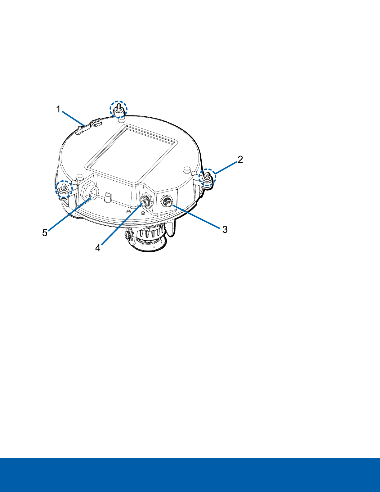
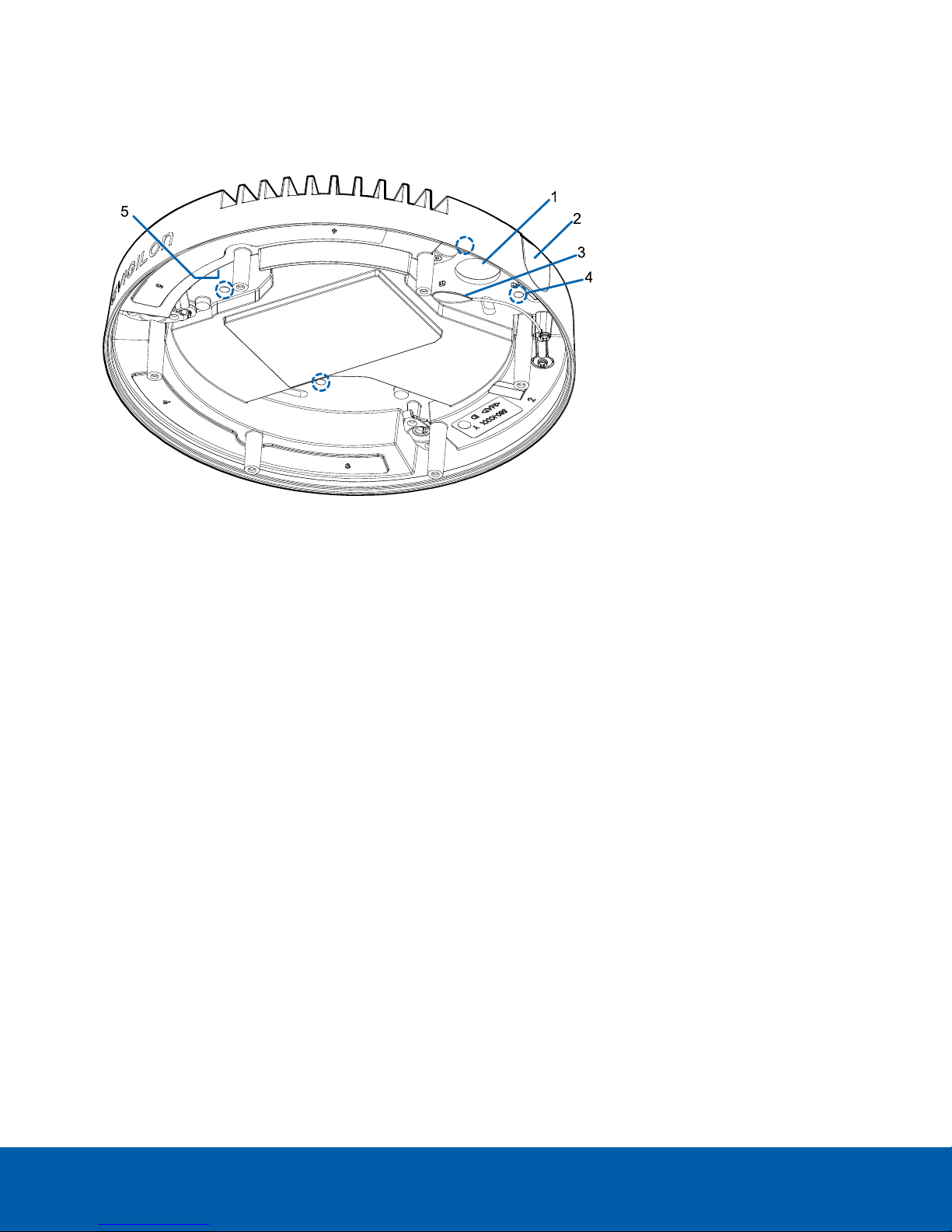
Camera Back View
1.1.
Lanyard anchor
The safety lanyard attaches to the anchor to prevent the camera from falling during installation.
2.
Camera mounting screws
Captive screws to fix the camera to the mounting adapter.
3.
IR ring cable connector
Accepts IR cable connection to power and control the IR illuminator ring.
4.
Audio, I/O, Aux power connector
Accepts connection of the audio, I/O, and Aux power pigtail connector.
5.
Ethernet port
Accepts an Ethernet connection to a network. Server communication and image data transmission occurs
over this connection. Also receives power when it is connected to a network that provides Power over
Ethernet.
Overview 7
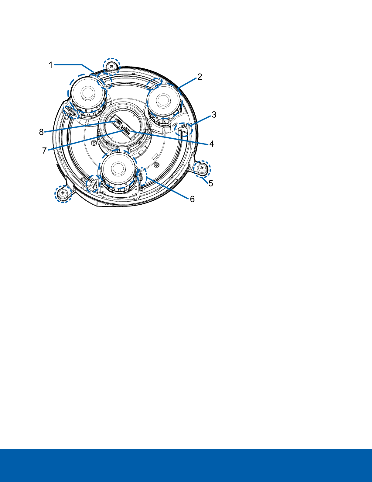
Camera Top View
1.
Serial number tag
Device information, product serial number and part number label.
2.
Camera heads
The multiple camera heads that can be moved, aimed and focused to monitor different scenes.
NOTE: There may be three or four camera heads depending on your camera model.
3.
Pan lock latch
Provides a locking mechanism for the image pan adjustment.
4. Firmware revert button
Resets the H4 Multisensor camera. For more information, see Resetting to Factory Default Settings on
page63.
5.
Camera mounting screws
Captive screws to fix the camera to the mounting adapter.
6.
Tilt lock thumb screw
Provides a locking mechanism for the image tilt adjustment.
7.
microSD card slot
Accepts a microSD card for onboard storage.
8.
Micro USB port
Accepts a micro USB to USB adapter. Only required when using the Avigilon USB Wi-Fi Adapter.
Camera Top View 8
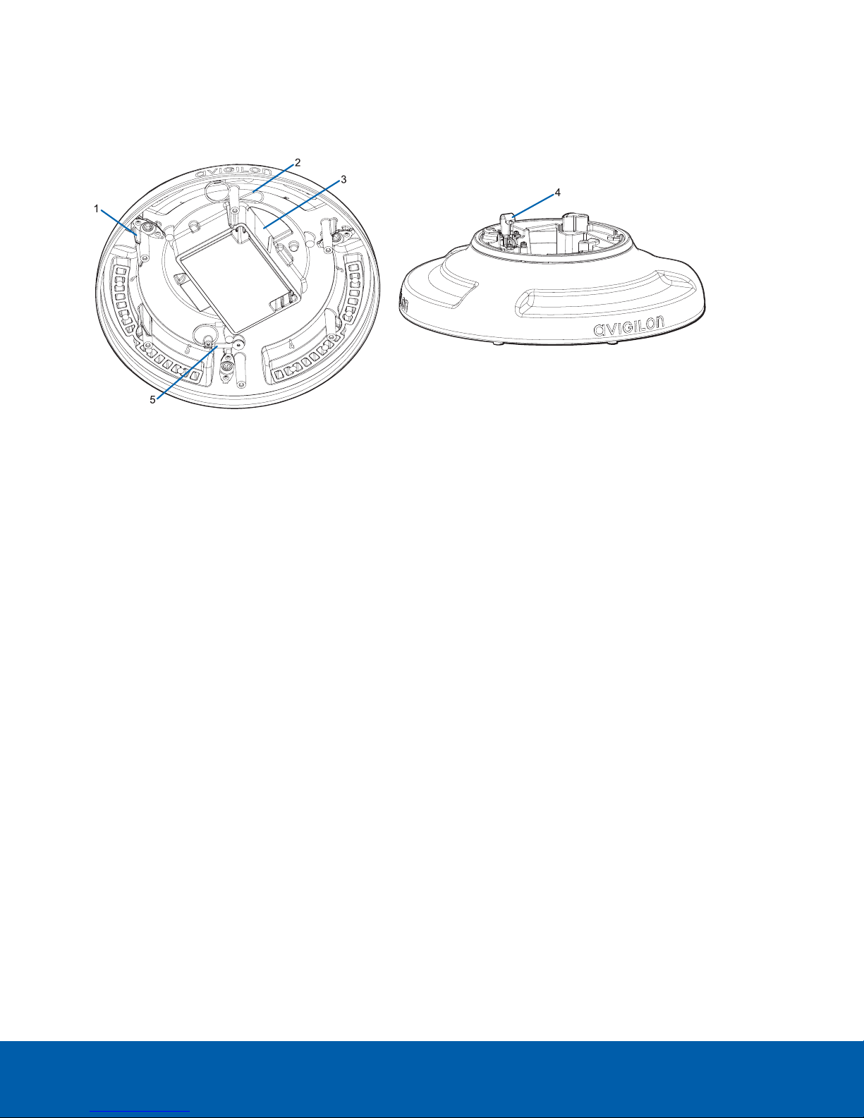
Surface Mount Adapter
1. Cable entry hole (rear)
An entry hole for the cables required for camera operation.
2. Cable entry hole (side)
An entry hole for the cables required for camera operation.
3. Lanyard to dome cover
Connects to the lanyard anchor on the dome cover.
4.
Mounting holes
Mounting points for the mount adapter.
5. Lanyard to camera
Connects to the lanyard anchor on the camera base.
Surface Mount Adapter 9
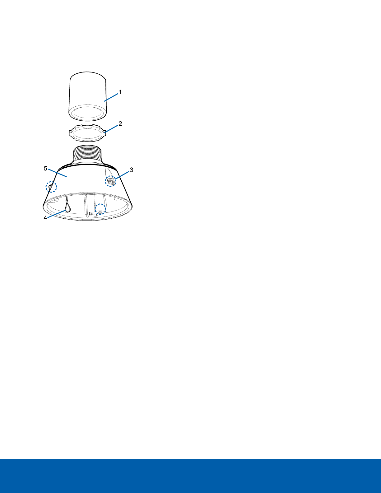
Pendant Mount Adapter
1.
Orange ribs
Two orange-colored ribs that are used to align with the lanyard clip on the dome cover.
2. Lanyard to dome cover
Connects to the lanyard anchor on the dome cover.
3.
Cable entry hole
An entry hole for the cables required for camera operation.
4.
Lanyard anchor
The safety lanyard attaches to the anchor to prevent the adapter from falling during installation.
5. Lanyard to camera
Connects to the lanyard anchor on the camera base.
Pendant Mount Adapter 10
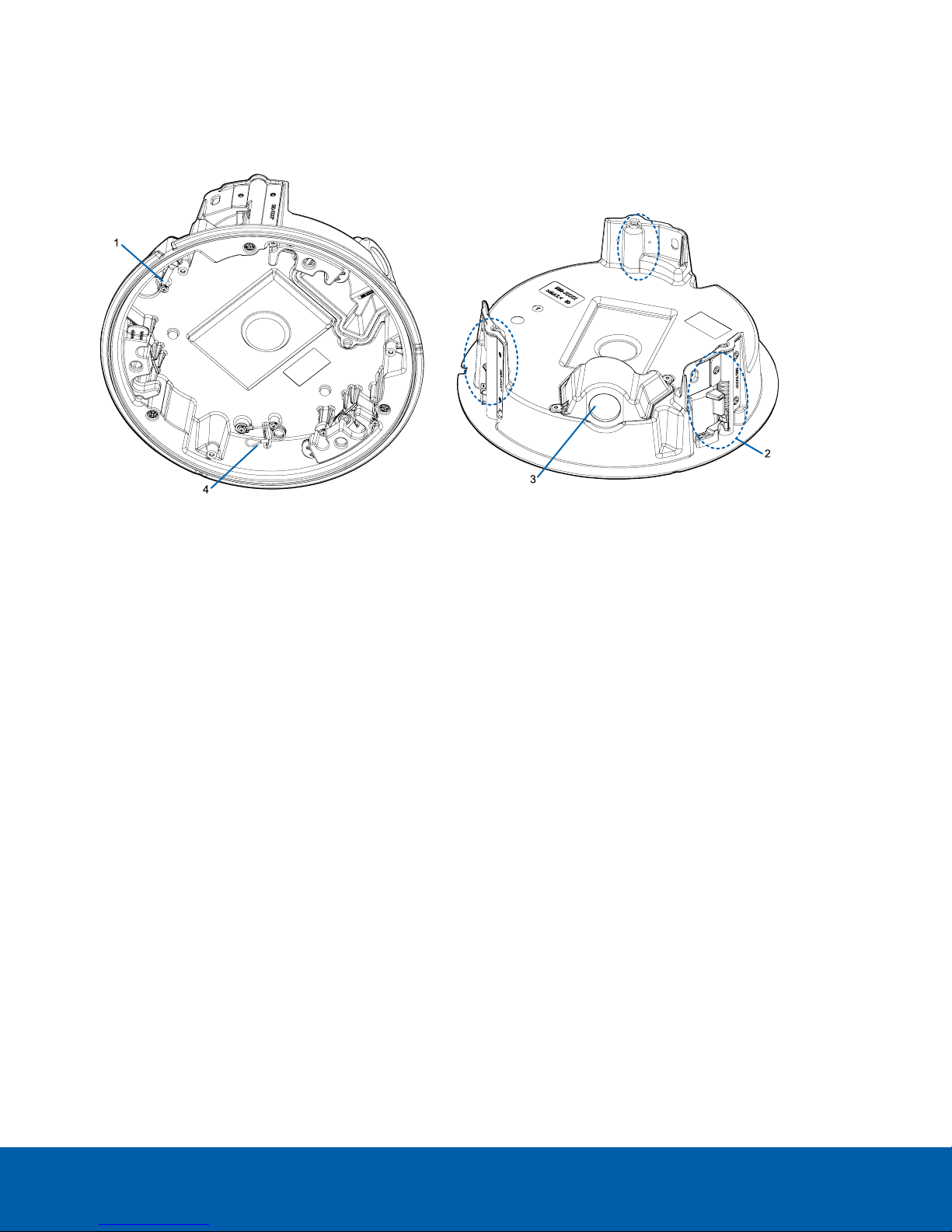
In-Ceiling Mount Adapter
1. Lanyard to camera
Connects to the lanyard anchor on the camera base.
2.
Clamps
Spring loaded locking mechanisms that secure the camera to the mounting surface.
3. Cable entry hole and conduit cable entry cover
An entry hole for the cables required for camera operation.
4. Lanyard to dome cover
Connects to the lanyard anchor on the dome cover.
In-Ceiling Mount Adapter 11
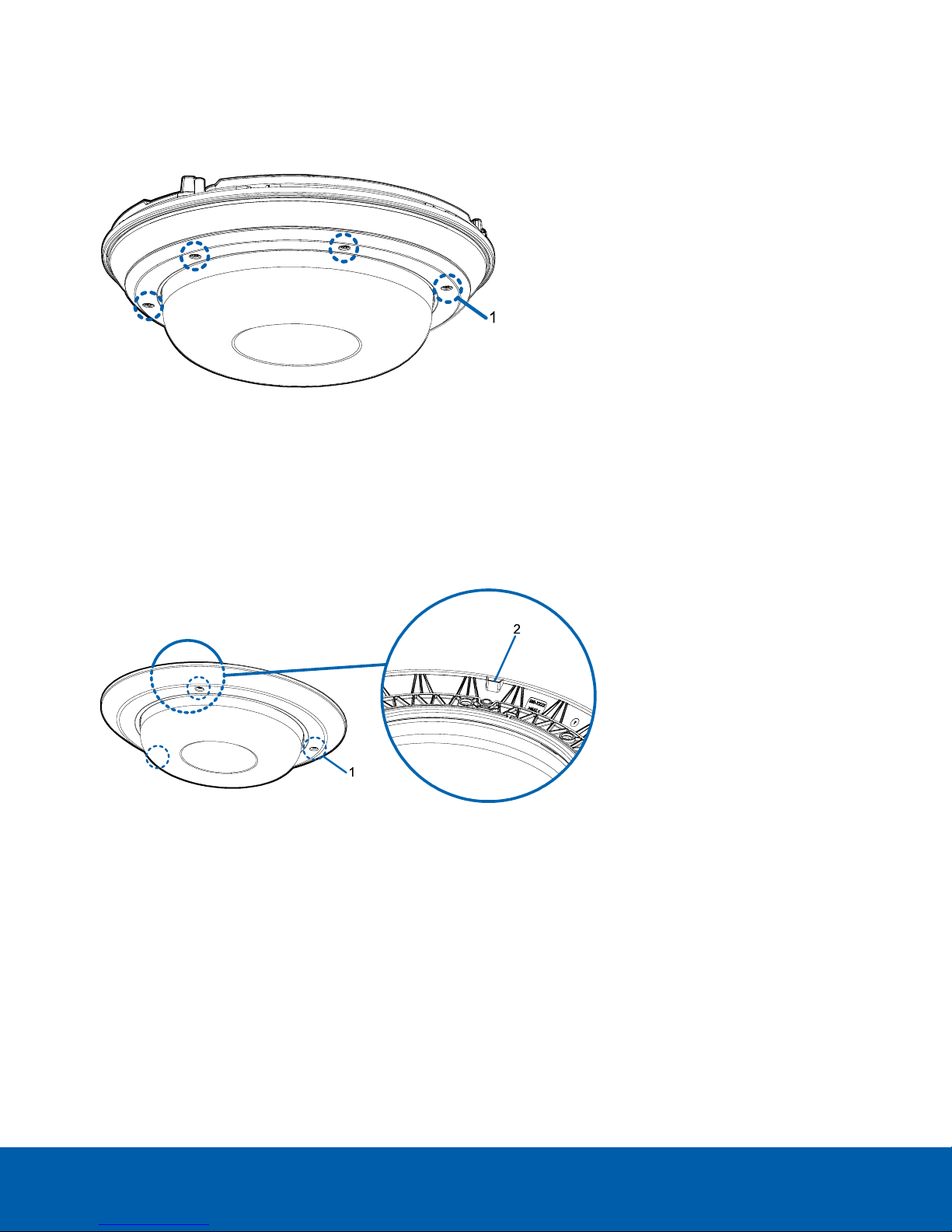
Outdoor Dome Cover
1.
Tamper resistant screws
Star-shaped captive screws to fix the dome cover to the base.
NOTE: There are 6 captive screws on the dome cover. Only 4 screws are shown in the figure above.
In-Ceiling Dome Cover
1.
Tamper resistant screws
Star-shaped captive screws to fix the dome cover to the base.
2.
Dome cover notch
Notch used to align the dome cover with the mounting adapter clip notch when installing the dome
cover.
Outdoor Dome Cover 12
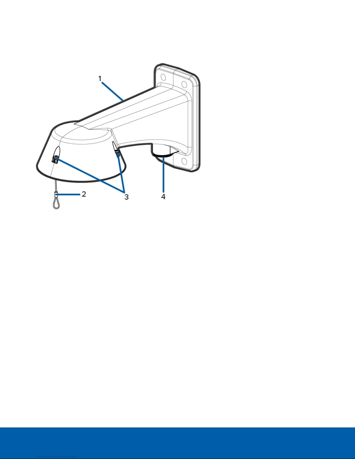
Pendant Wall Mount
1.
Pendant wall mount
Camera mount for walls and other mounting surfaces.
2.
Lanyard
Connects to the lanyard anchor on the mounting adapter.
3.
Tamper resistant screws
Star-shaped captive screws to fix the mounting adapter to the pendant wall mount.
NOTE: There are 3 captive screws on the pendant mount. Only 2 screws are shown in the figure above.
4.
NPT pipe entry hole
A 3/4” NPT threaded hole for NPT pipe conduits.
Pendant Wall Mount 13
Pendant NPT Mount
1.
NPT pipe
NPT pipe used for a pendant mount with the NPT adapter (IRPTZ-MNT-NPTA1).
NOTE: The NPT pipe is not an included accessory supplied by Avigilon and should be sourced
separately.
2.
Lock nut
Locking nut for securing the pendant NPT mount on the NPT pipe.
3.
Tamper resistant screws
Star-shaped captive screws to fix the mounting adapter to the pendant NPT mount.
NOTE: There are 3 captive screws on the NPT mount. Only 2 screws are shown in the figure above.
4.
Lanyard
Connects to the lanyard anchor on the mounting adapter.
5.
NPT adapter
Used to mount the dome camera to NPT pipes.
Pendant NPT Mount 14

Pendant Mount Installation
Camera Package Contents
The H4 Multisensor camera has a variety of different mounting, dome cover, camera and accessory options. The
components for each H4 Multisensor camera will arrive in a camera package, a dome cover package, a
mounting adapter package, a mount package (for pendant mount cameras), and an optional IR Ring package.
Ensure the camera package contains the following:
l Avigilon H4 Multisensor Camera module. A 3- or 4-sensor camera module with 3 MP, 5 MP, or 4K (8 MP)
resolution per sensor.
l Audio, external power, and I/O pigtail cable connector
l RJ45 CAT5E plugs (x2)
l RJ45 connector waterproof gland
Ensure the Pendant mount adapter package contains the following:
l Pendant mount adapter (H4AMH-AD-PEND1)
l Installation instructions sheet
If you are installing the camera with the pendant wall mount, ensure the package includes the following:
l Pendant wall mount (IRPTZ-MNT-WALL1)
l Mounting template sticker
If you are installing the camera with the NPT mount, ensure the package includes the following:
l NPT mount (IRPTZ-MNT-NPTA1)
l Lock nut
l Thread sealing tape
Ensure the dome cover package contains the following:
l Clear or smoked dome bubble and cover (H4AMH-DO-COVR1 or H4AMH-DO-COVR1-SMOKE)
If you are installing the camera with the optional IR illuminator, ensure the package includes the following:
l Optional IR illuminator ring (H4AMH-AD-IRIL1)
Installation Steps
Complete the following sections to install the device.
(Optional) Installing the Pendant Wall Mount
Use the procedure below to install the pendant wall mount (IRPTZ-MNT-WALL1) for use with the H4 Multisensor
pendant mount adapter (H4AMH-AD-PEND1).
Pendant Mount Installation 15
CAUTION — The dome camera must be mounted as instructed below or problems with moisture may
arise and will not be covered by the dome camera warranty.
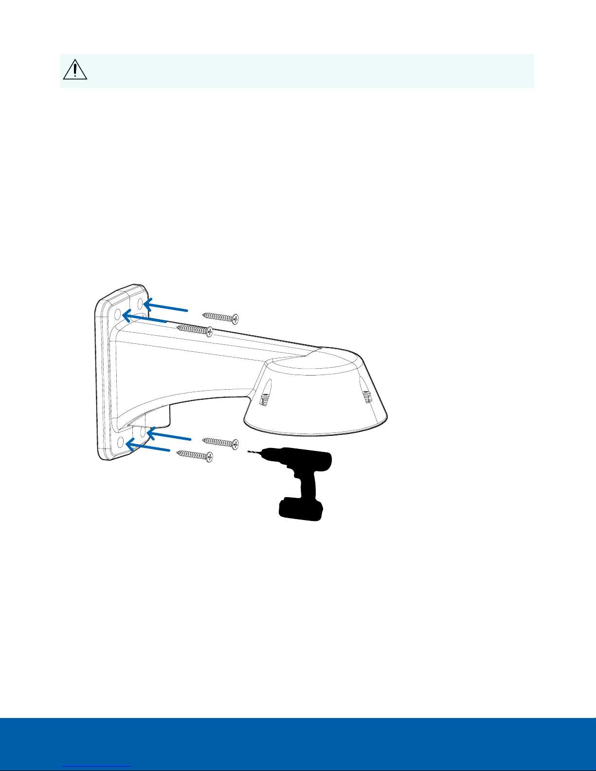
1. Determine where the cable will enter the pendant wall mount.
l If the cable will be pulled from inside the mounting surface, use the cable entry hole at the rear of
the pendant wall mount.
l If the cable will be coming out of an external conduit pipe, use the 3/4” NPT pipe entry hole on the
bottom of the pendant wall mount.
2. Use the provided mounting template to drill four mounting holes into the mounting surface.
l If you are using the rear cable entry hole, also drill the cable entry hole into the mounting surface.
3. Pull the required cables through the preferred cable entry hole on the pendant wall mount.
l If you are using the pipe entry hole, pull the cables through the pipe conduit then the wall mount.
Next, apply thread seal tape to the pipe conduit and screw it into the pipe entry hole.
4. Fasten the pendant wall mount to the mounting surface.
5. Tighten the wall mount screws to secure the wall mount to the wall.
(Optional) Installing the Pendant Wall Mount 16
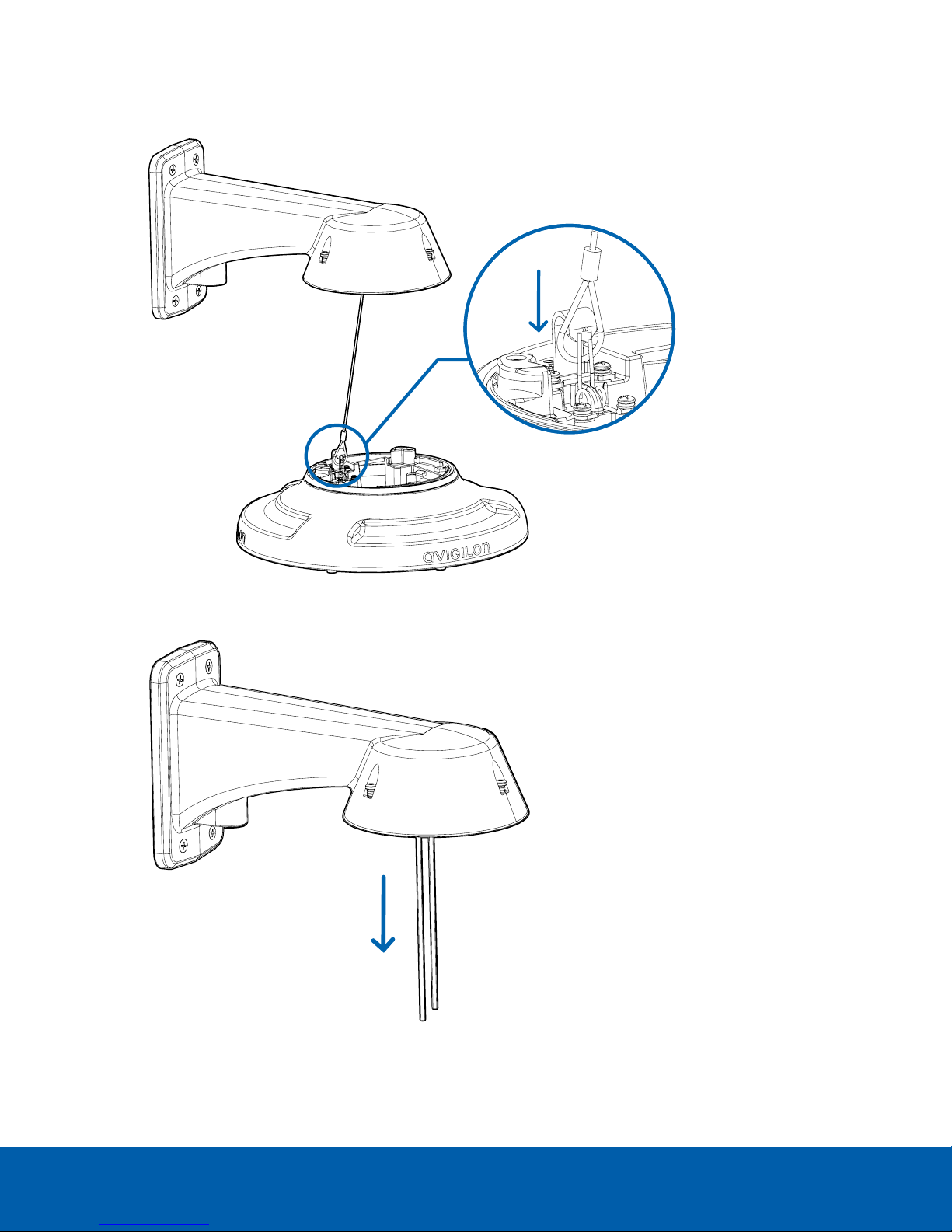
6. Connect the safety lanyard from the mount to the anchor on the pendant adapter.
7. Pull the cables through the pendant wall mount.
(Optional) Installing the Pendant Wall Mount 17
(Optional) Installing the NPT Mount Adapter
CAUTION — The dome camera must be mounted as instructed below or problems with moisture may
arise and will not be covered by the dome camera warranty.
If you are installing the H4 Multisensor camera with an NPT adapter (IRPTZ-MNT-NPTA1), the dome camera must
be mounted on a 1-1/2” NPT female threaded wall or ceiling mounting bracket. The mounting bracket is not
included in the camera package.
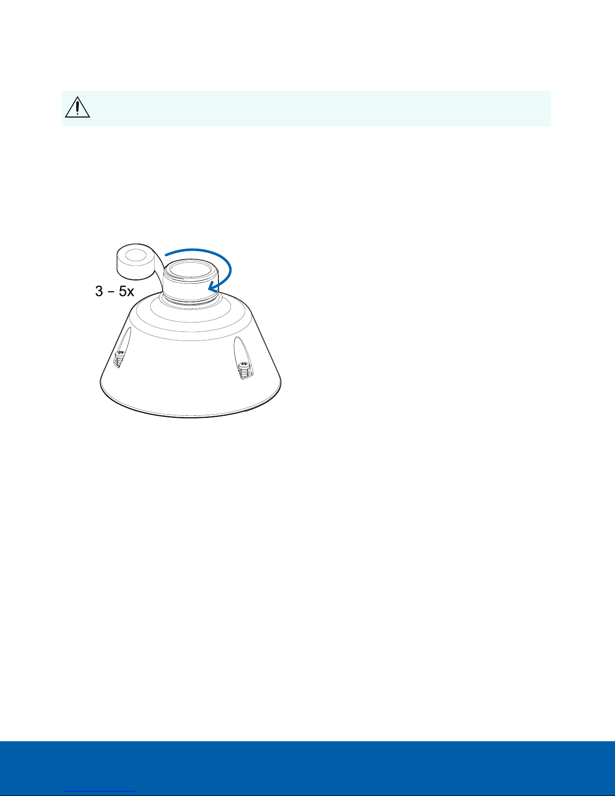
1.1. Wrap the thread of the NPT adapter with the supplied thread-sealing tape to create a water tight seal
around the camera connection. There should be three to five turns around the entire threaded surface.
When applying the thread-sealing tape, wrap the tape clockwise.
This will ensure the tape does not unravel when installing the mating parts together.
Tip: Always apply thread-sealing tape to threaded mounts to help prevent the threads from binding.
(Optional) Installing the N PT Mount Adapter 18
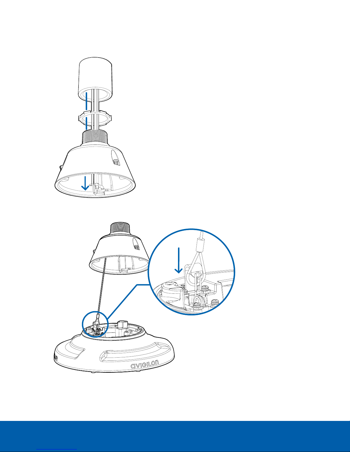
2. Loosely thread the lock nut onto the NPT adapter, then secure the NPT adapter into the wall or ceiling
mounting bracket.
3. Connect the safety lanyard from the mount to the anchor on the pendant adapter.
4. Pull the cables through the mounting bracket and adapter.
(Optional) Installing the N PT Mount Adapter 19
Installing the Pendant Mounting Adapter
Use the following procedure to mount the pendant adapter (H4AMH-AD-PEND1) into a pendant wall mount
(IRPTZ-MNT-WALL1) or NPT mount (IRPTZ-MNT-NPTA1).
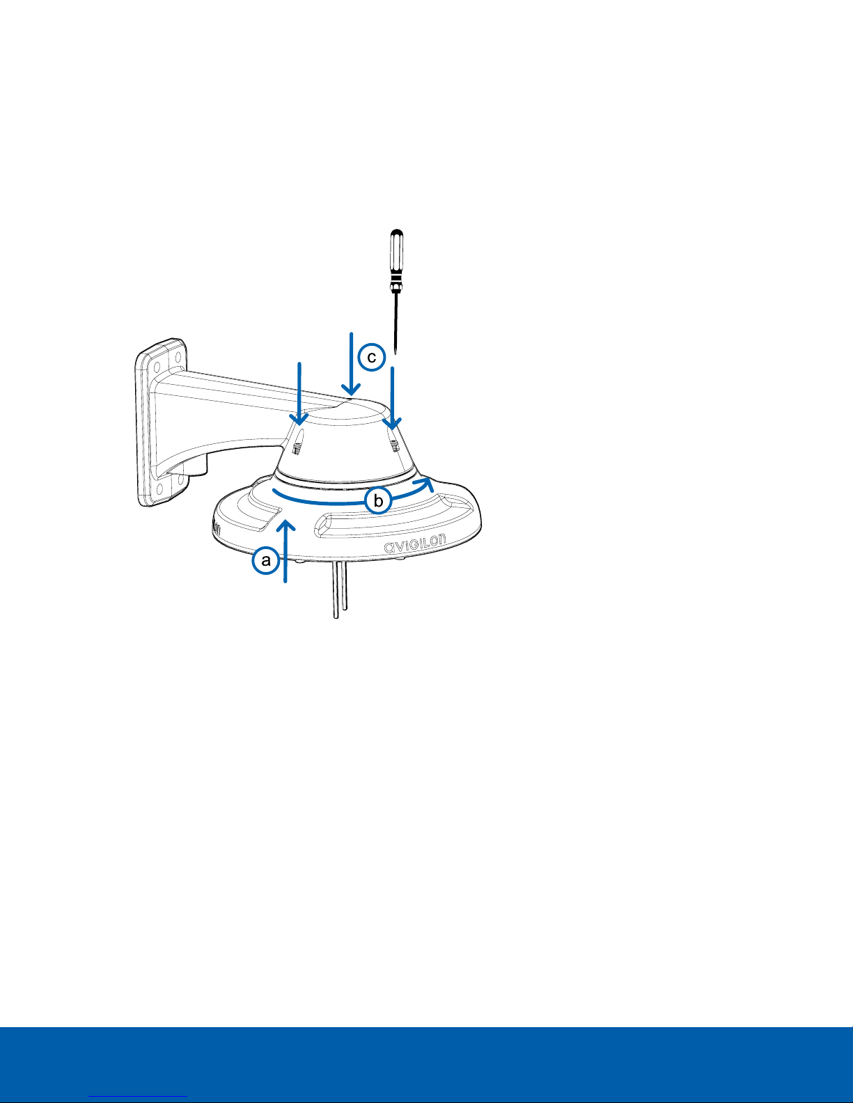
1. Connect the pendant adapter to the mount. In one smooth motion, raise the adapter into the mount (a)
and then turn clockwise to lock the adapter in place (b).
2. Use a screwdriver to tighten the 3 setscrews at the top of the mount to secure the pendant adapter to the
mount (c).
Installing the Pendant Mounting Adapter 20
 Loading...