

Avidyne Entegra EXP5000, FLIGHTMAX Entegra, Piper Meridian EXP5000 Pilot's Manual
600-00104-001 Rev 01
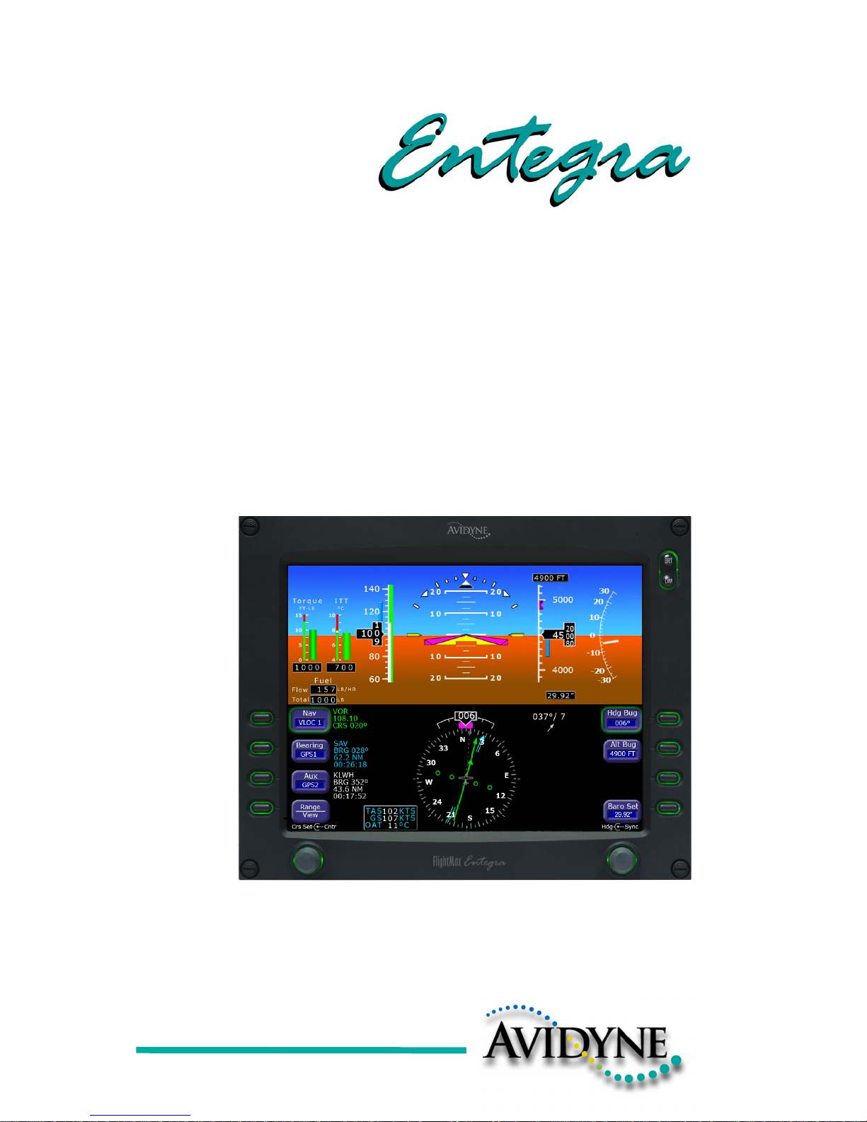
Piper Meridian
EXP5000
Primary Flight Display
Pilot’s Guide


600-00104-001 Rev 01 -i- Entegra EXP5000 PFD
Document Revision History
This document is applicable to Software Part Number 530-00177-000.
All materials copyrighted including images that represent this software
Copyright 2005 Avidyne Corporation. All rights reserved.
Date Revision Description
Sept. 30, 2005 00 Released per ECO-05-162
Oct. 14, 2005 01 Updated per ECO-05-179

600-00104-001 Rev 01 -ii- Entegra EXP5000 PFD
Table of Contents
1 Introduction.............................................................. 1
Notes and Warnings 1
Copyrights and Trademarks 2
AVIDYNE EXCLUSIVE LIMITED WARRANTY/LIMITATIONS ON
LIABILITY .................................................................................... 3
2 EXP5000 System Overview..................................... 5
Entegra EXP5000 Overview 5
EXP5000 Upper Half Display ...................................................... 7
Upper Half Display ................................................................ 7
EXP5000 Display Options................................................... 10
EXP5000 Lower Half Display .................................................... 12
EXP5000 Buttons and Knobs.................................................... 15
Left Buttons and Knob......................................................... 15
Nav, Bearing, and Aux Data Blocks.................................... 17
Right Buttons and Knob ...................................................... 18
3 Flying with the EXP5000........................................ 21
Introduction 21
Starting the EXP5000 ................................................................ 22
EXP5000 Alignment Messages........................................... 23
AHRS Alignment Errors ...................................................... 24
Startup Settings ........................................................................ 25
Setting Up the HSI..................................................................... 26
Using GPS/VHF Systems with the EXP5000 ............................ 27
Controlling the Autopilot ............................................................ 28
S-TEC 1500 Horizontal Modes .......................................... 28
Flight Director Modes .......................................................... 29
Precision Flying with EXP5000.................................................. 30
Obtaining Level Flight ......................................................... 30
Flying a Constant Rate Turn ............................................... 30
Using Trend Indicators........................................................ 31
Using the EXP5000 for Approaches.......................................... 33
Precision Approaches ......................................................... 33
Non-Precision Approaches ................................................. 34
4 Using Dual PFDs.................................................... 36
Selecting the ADAHRS Source 36

600-00104-001 Rev 01 -iii- Entegra EXP5000 PFD
Synchronized and Non-synchronized Controls ......................... 38
Pilot Priority Switch.................................................................... 40
Dual PFD Error Conditions ........................................................ 41
ADAHRS Miscompares....................................................... 41
PFD-to-PFD Communication Fault ..................................... 41
5 Invalid Sensors and Error Conditions ................. 43
Invalid Air Data .......................................................................... 44
Invalid Heading.......................................................................... 45
Crosscheck Monitor................................................................... 46
Warmstart Conditions ................................................................ 48
Recoverable Attitude ................................................................. 49
Invalid Attitude & Heading ......................................................... 50
Invalid Engine Data ................................................................... 51
Nav Source Crosscheck ............................................................ 52
6 Software License ................................................... 53

Entegra EXP5000 PFD -iv- 600-00104-001 Rev 01
This page intentionally blank.
600-00104-001 Rev 01 -1- Entegra EXP5000 PFD
1 Introduction
This Pilot’s Guide provides information about the Entegra EXP5000
PFD for the Piper Meridian:
1.1 Notes and Warnings
Notes and warnings provide guidance for the use of the EXP5000.
Avidyne strongly suggests that you pay close attention to notes and
warnings for your own safety.
For example:
The instructions and warnings in this manual are not intended to
replace the instructions and warnings for other equipment on your
aircraft. It is critical that you as the pilot in command have a complete
understanding of the warnings, operating instructions, and limitations
for all equipment installed on your aircraft.
Note: All images contained within this document, including screenshots and
other displays, are for reference use only and are subject to change. The
images contained herein may differ slightly from your actual equipment or
display.
Note: Notes provide useful information about how to use the EXP5000
Primary Flight Display.
!
Warnings are prefaced with exclamation points and denote
information that can prevent serious injury or death on the
part of the user.
!
This manual assumes that the reader is an appropriately
licensed pilot. Avidyne strongly recommends that you use the
EXP5000 only under VFR conditions until you are very familiar
with the EXP5000.
If you have questions, please contact Avidyne at 800-284-
3963 (800-AVIDYNE) before operating with the Entegra PFD
under IFR conditions.

Introduction
Entegra EXP5000 PFD -2- 600-00104-001 Rev 01
1.2 Copyrights and Trademarks
All trademarks and trade names are the property of their respective
owners.
All materials copyrighted including images that represent this
software.
Copyright 2005 Avidyne Corporation. All rights reserved.
!
When using the EXP5000, be sure to cross-check the data
displayed against other data sources for accuracy including
other flight deck instruments and charts.

AVIDYNE EXCLUSIVE LIMITED WARRANTY/LIMITATIONS ON LIABILITY
600-00104-001 Rev 01 -3- Entegra EXP5000 PFD
1.3 AVIDYNE EXCLUSIVE LIMITED WARRANTY/
LIMITATIONS ON LIABILITY
Avidyne warrants the Product manufactured by it against defects in material and
workmanship for a period of twenty-four (24) months from delivery. If Avidyne's
Product fails to conform to this warranty, Avidyne, in its sole discretion, will either
repair or replace the Product or provide a refund of the purchase price paid for the
Product. This warranty is made upon the express conditions that:
(a) Avidyne is given prompt written notice of any claimed non-conformity in the
Product, with a reasonable explanation thereof;
(b) The Product is returned to Avidyne or to an Avidyne authorized service facility;
(c) The Product has not been altered in any manner other than as previously authorized
by Avidyne in writing; and
(d) Repairs to the Product have not been made by anyone other than Avidyne or an
Avidyne authorized service facility.
This warranty does not apply to any Product which is not installed, maintained and
operated in accordance with Avidyne's written instructions or which is otherwise
misused, including, without limitation, to any Product which is damaged due to
improper installation, maintenance or operation, tampering, alteration of serial numbers
or other manufacturers data, lightning or other electrical source, or otherwise.
If warranty protection is applicable to the Product, Avidyne will use reasonable efforts
to repair or replace Product within ten (10) business days of its receipt of the Product.
Any Product that has been repaired by Avidyne or replaced by Avidyne under this
warranty will be subject to remainder of the original warranty term applicable to the
repaired or replaced Product or will be warranted under the warranty terms above for
ninety days from the date of repair or replacement, whichever period is longer.
THIS EXCLUSIVE LIMITED WARRANTY APPLIES IN LIEU OF AND EXPRESSLY
SUPERCEDES AND EXCLUDES ALL OTHER REPRESENTATIONS, AFFIRMATIONS
AND/OR WARRANTIES, WHETHER EXPRESS OR IMPLIED, ORAL OR WRITTEN,
INCLUDING, WITHOUT LIMITATION, ANY WARRANTY OF MERCHANTABILITY, OF
FITNESS FOR A PARTICULAR PURPOSE, OF TITLE AND/OR OF NON-INFRINGEMENT.
PURCHASER EXPRESSLY AND KNOWINGLY AGREES THAT NO OTHER
REPRESENTATIONS, AFFIRMATIONS OR WARRANTIES, WHETHER EXPRESS OR
IMPLIED, ORAL OR WRITTEN, FORM PART OF ANY PURCHASE AND SALE
TRANSACTION RELATED TO THE PRODUCT.
AVIDYNE'S (AND ITS AFFILIATES') AND ANY PRODUCT COMPONENT SUPPLIER'S
SOLE RESPONSIBILITY AND LIABILITY RELATED TO THE PRODUCT OR ARISING OUT
OF OR RELATED TO ITS PURCHASE, SALE, PERFORMANCE, RELIABILITY OR USE
ARE LIMITED TO ITS REPAIR OR REPLACEMENT, OR TO A REFUND OF THE
PURCHASE PRICE, IN AVIDYNE'S SOLE DISCRETION. IN NO EVENT WILL AVIDYNE
(OR ITS AFFILIATES) OR ANY SUPPLIERS OF PRODUCT COMPONENTS BE
RESPONSIBLE OR LIABLE FOR ANY OTHER DAMAGE OF ANY NATURE
WHATSOEVER, INCLUDING DIRECT, INDIRECT, INCIDENTAL, CONSEQUENTIAL,
SPECIAL, LOSS OF USE, LOSS OF REVENUE OR PROFIT, PROPERTY DAMAGE,
PERSONAL INJURY, WRONGFUL DEATH, OR OTHER DAMAGE (WHETHER OR NOT

Introduction
Entegra EXP5000 PFD -4- 600-00104-001 Rev 01
AVIDYNE (OR ITS AFFILIATES) WERE NOTIFIED OF THE POSSIBILITY THAT ANY
DAMAGE MIGHT BE INCURRED), ARISING OUT OF OR RELATED TO THE PRODUCT,
ITS PURCHASE OR SALE, ITS PERFORMANCE OR RELIABILITY, OR THE USE OR
INABILITY TO USE THE PRODUCT, FOR ANY REASON, INCLUDING DUE TO ANY
PRODUCT DEFECT OR DEFECTS OR ANY ACTION OR INACTION OF ANY NATURE
(INCLUDING CLAIMED OR ACTUAL NEGLIGENCE OR GROSS NEGLIGENCE) BY
AVIDYNE OR ANY SUPPLIERS OF PRODUCT COMPONENTS. NEITHER THIS
EXCLUSIVE LIMITED WARRANTY NOR AVIDYNE'S OR ANY PRODUCT COMPONENT
SUPPLIER'S RESPONSIBILITY OR LIABILITY WILL IN ANY WAY BE ENLARGED OR
OTHERWISE ALTERED DUE TO AVIDYNE'S PROVISION OF TECHNICAL SUPPORT OR
TRAINING RELATED TO THE PRODUCT.
WITHOUT LIMITING THE FOREGOING, NEITHER AVIDYNE (NOR ITS AFFILIATES)
MAKE ANY REPRESENTATIONS, AFFIRMATIONS OR WARRANTIES REGARDING OR
RELATED TO PRODUCTS NOT MANUFACTURED BY AVIDYNE OR REGARDING OR
RELATED TO THE PERFORMANCE OR RELIABILITY OF ANY SUCH PRODUCT, EITHER
ALONE OR WHEN USED WITH ANY PRODUCT MANUFACTURED BY AVIDYNE, OR THE
SUITABILITY OF ANY SUCH PRODUCT FOR USE WITH ANY PRODUCT
MANUFACTURED BY AVIDYNE. AVIDYNE (AND ITS AFFILIATES) EXPRESSLY
DISCLAIM ANY AND ALL REPRESENTATIONS, AFFIRMATIONS AND/OR WARRANTIES
REGARDING OR RELATED TO ANY SUCH PRODUCTS. IN NO EVENT WILL AVIDYNE
(OR ITS AFFILIATES) BE RESPONSIBLE OR LIABLE FOR ANY DAMAGE OF ANY
NATURE WHATSOEVER, INCLUDING DIRECT, INDIRECT, INCIDENTAL,
CONSEQUENTIAL, SPECIAL, LOSS OF USE, LOSS OF REVENUE OR PROFIT,
PROPERTY DAMAGE, PERSONAL INJURY, WRONGFUL DEATH, OR OTHER DAMAGE
(WHETHER OR NOT AVIDYNE (OR ITS AFFILIATES) WERE NOTIFIED OF THE
POSSIBILITY THAT ANY DAMAGE MIGHT BE INCURRED), ARISING OUT OF OR
RELATED TO PRODUCTS NOT MANUFACTURED BY AVIDYNE, THE PURCHASE OR
SALE OF SUCH PRODUCTS, THEIR PERFORMANCE OR RELIABILITY, EITHER ALONE
OR WHEN USED WITH ANY PRODUCT MANUFACTURED BY AVIDYNE, OR THE
SUITABILITY OF ANY SUCH PRODUCT FOR USE WITH ANY PRODUCT
MANUFACTURED BY AVIDYNE.
THIS EXCLUSIVE LIMITED WARRANTY ALSO APPLIES IN LIEU OF AND EXPRESSLY
SUPERCEDES AND EXCLUDES ALL OTHER RIGHTS ANY PURCHASER HAS OR MAY
HAVE RELATED TO THE PRODUCT AND/OR ARISING OUT OF OR RELATED TO ITS
PURCHASE, SALE, PERFORMANCE, RELIABILITY OR USE, EITHER ALONE OR WITH
ANY OTHER PRODUCT OR PRODUCTS, WHETHER IN CONTRACT, IN TORT
(INCLUDING RIGHTS SOUNDING IN NEGLIGENCE, STRICT LIABILITY AND
MISREPRESENTATION), UNDER STATUTE, AT LAW, IN EQUITY, OR OTHERWISE, AND
PURCHASER EXPRESSLY AND KNOWINGLY WAIVES ALL SUCH RIGHTS TO THE
FULLEST EXTENT PERMITTED BY LAW. PURCHASER ALSO EXPRESSLY AND
KNOWINGLY AGREES THAT THE PRODUCT IS NOT A CONSUMER GOOD.
THE FOREGOING FOUR PARAGRAPHS DEFINE AND LIMIT AVIDYNE'S SOLE
RESPONSIBILITY AND LIABILITY AND PURCHASER'S SOLE AND EXCLUSIVE
REMEDIES RELATED TO THE PRODUCT.
Some jurisdictions may not allow the exclusion or limitation of warranties or liabilities,
in which case the above limitations or exclusions, or some of them,
may not apply in those jurisdictions.
600-00104-001 Rev 01 -5- Entegra EXP5000 PFD
2 EXP5000 System Overview
This section contains the following information:
● Entegra EXP5000 Overview, page 5
● EXP5000 Upper Half Display, page 7
● EXP5000 Lower Half Display, page 12
● EXP5000 Buttons and Knobs, page 15
2.1 Entegra EXP5000 Overview
This section provides an overview of the Entegra EXP5000 window.
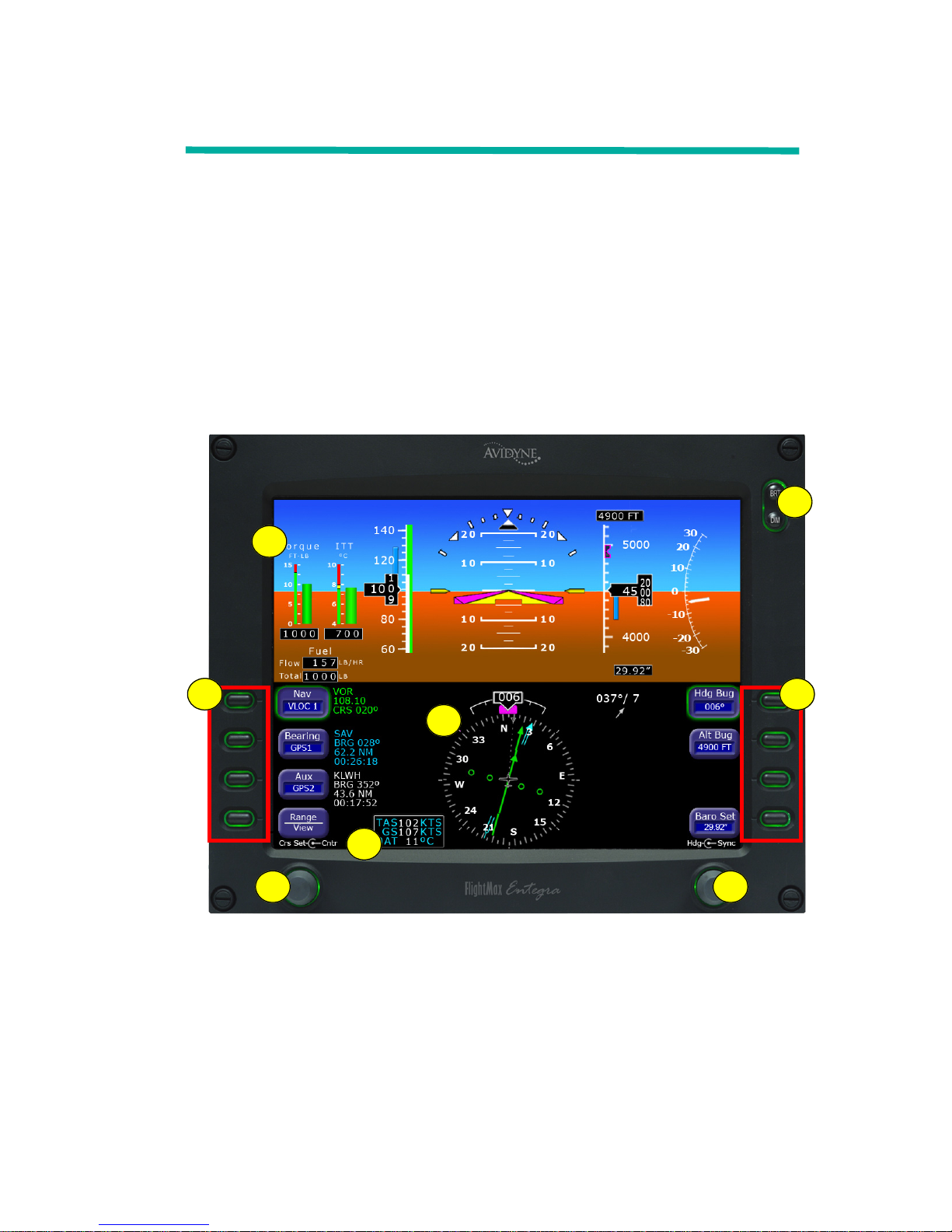
Figure 1. The Entegra EXP5000 PFD
1) Brightness Control (BRT/DIM)—Allows you to adjust the
display brightness. Press the top button to brighten the display;
press the bottom button to dim it. The default brightness is 75%.
1
6
3 3
2
4
5
6

EXP5000 System Overview
Entegra EXP5000 PFD -6- 600-00104-001 Rev 01
2) Upper Half Display—The upper half of your EXP5000 window
displays information about your power plant, aircraft attitude,
autopilot status (when equipped), navigation and more. This
section includes the following:
■ Engine instruments
■ Attitude Direction Indicator (ADI)
■ Airspeed Indicator (ASI)
■ Altimeter
■ Vertical Speed Indicator (VSI)
For information about the data displayed on the upper section of
the EXP5000 window, see Section 2.2, "EXP5000 Upper Half
Display" on page 7.
3) Buttons—Buttons allow you to display new information or
change the display. Button labels change to reflect the current
environment.
4) Lower Half Display—Displays the Horizontal Situation Indicator
(HSI) and other details about direction, windspeed, and flight
plans. The HSI can display a moving map to help you determine
your exact location. For more information, see Section
2.3, "EXP5000 Lower Half Display" on page 12.
5) Air Data Data Block— Contains Air Data information.
6) Left and Right Knobs—Knobs allow you to change the display
as indicated for the particular settings. The knob labels change to
indicate the active function.
■ Left button and knob functions are described in Left Buttons
and Knob, on page 15.
■ Right button and knob functions are described in Right
Buttons and Knob, on page 18.
EXP5000 Upper Half Display
600-00104-001 Rev 01 -7- Entegra EXP5000 PFD
2.2 EXP5000 Upper Half Display
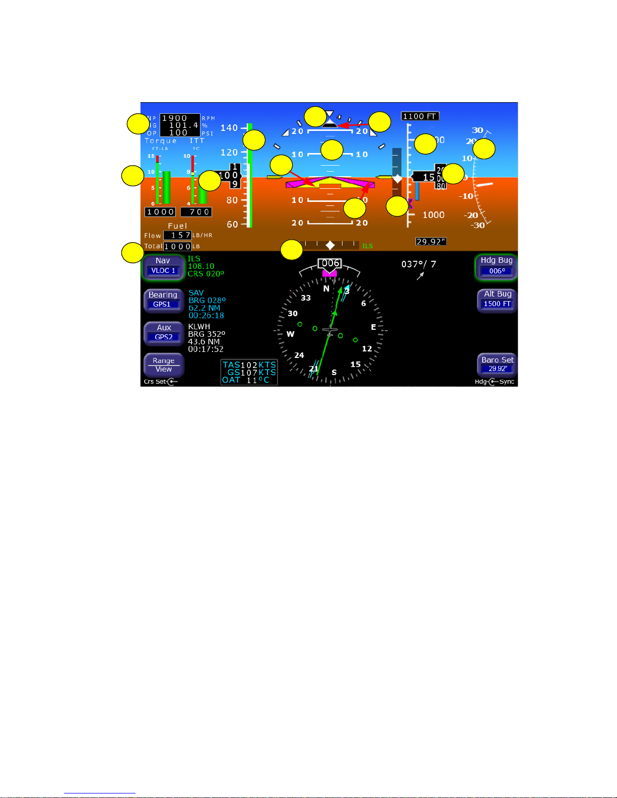
Figure 2. EXP5000 Upper Half Display Symbols
Upper Half Display
The upper portion of the EXP5000 contains the following information:
1) Engine Start Parameters—During engine start or parameter
exceedance, numeric displays of the following parameters are
provided.
■ Propeller Speed (Np)—Units of RPM.
■ Gas Turbine Speed (Ng)—Units of %.
■ Oil Pressure (OP)—Units of PSI.
2) Torque and Inter-Turbine Temperature (ITT) Gauges:
■ Torque Gauge—Displays current engine torque in foot-
pounds. A numeric display below the torque analog indicator
displays the torque value to the nearest 10 foot-pound. If the
torque enters the warning (red) area, the analog indicator bar
and numeric readout out display in red.
■ ITT—Displays current engine ITT in °C. A numeric display
below the ITT analog indicator displays the ITT value to the
11
15
13
12
9
14
8
4
5
7
6
2
1
3
10

EXP5000 System Overview
Entegra EXP5000 PFD -8- 600-00104-001 Rev 01
nearest 5°C. If the ITT enters the caution (yellow) or warning
(red) area, the analog indicator bar and numeric readout out
display in the corresponding color.
3) Fuel Flow and Fuel Quantity:
■ Flow—Displays the current engine fuel flow as a numeric
display, to the nearest 1 pound per hour (or 1 kilogram per
hour if metric units are selected).
■ Total—Displays the total (left plus right) fuel quantity to the
nearest 5 pounds (or 2 kilograms if you select metric units).
4) Airspeed Tape—Indicated airspeed with a display range from 20
kts to 300 kts. Each minor graduation represents 5 knots and
each 20 knot major graduation is labeled. Color bands on the
airspeed tape are as follows:
5) Airspeed Window—Displays current indicated airspeed in knots.
Hash marks are displayed below 20 knots.
6) Bank Angle Indicator—The bank angle indicator is composed of
an inverted white triangle and an upright white triangular Roll
Pointer. The upright white triangle points to the current bank
angle. Graduations are at 0, 10, 20, 30, 45, & 60 degrees. (Note:
The 0 and 45 degree marks are inverted triangles).
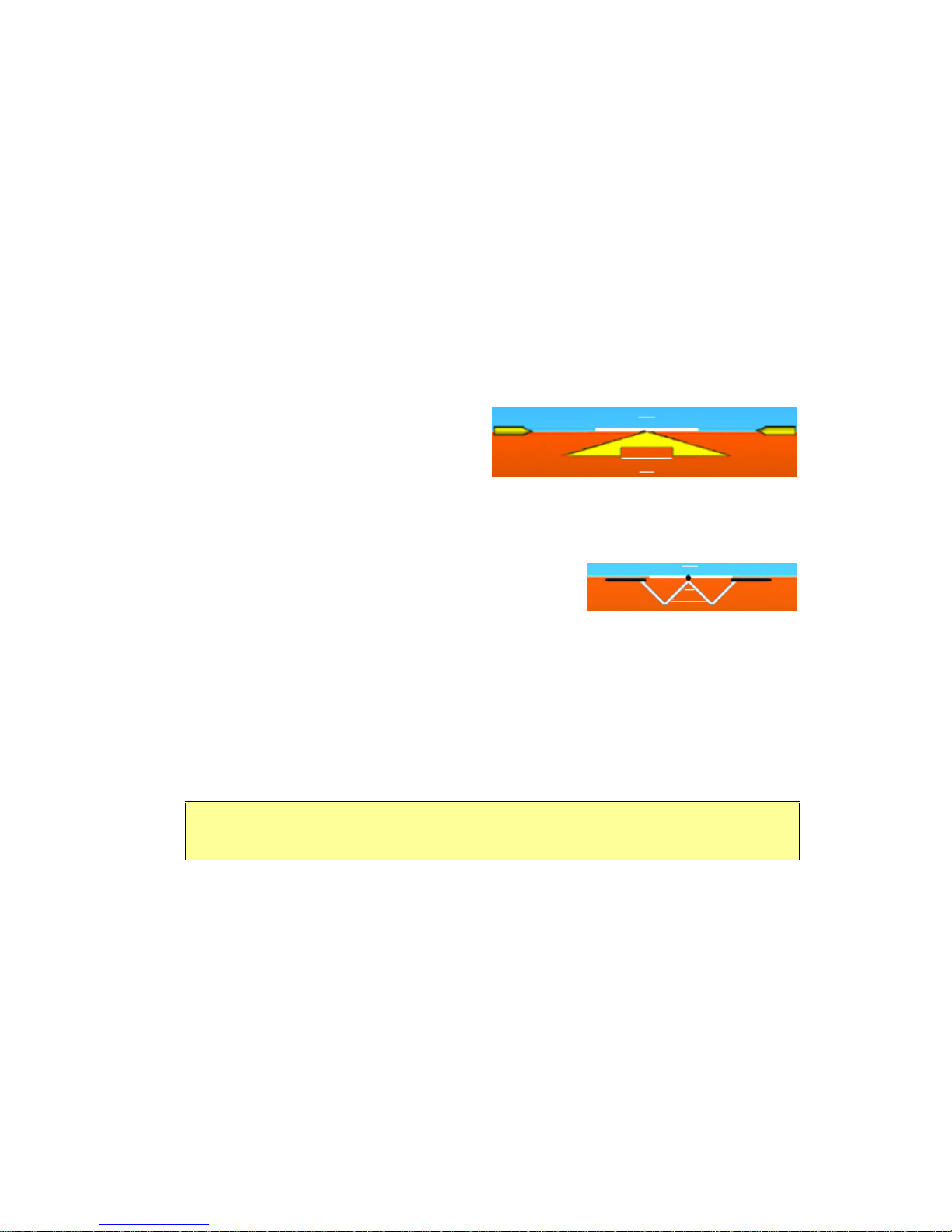
7) Skid/Slip Indicator—The black trapezoid is centered under the
roll pointer in coordinated flight. Full scale deflection is the width
of the trapezoid.
8) Pitch Ladder—The pitch ladder is marked as follows:
■ Every 2 1/2° within the range of ± 20°.
■ Every 5° from +20° to +50° and -20° to -30°.
Band
Color
Meaning
Red VNEVMO up to top of the airspeed tape.
Green
VS up to VMO.
White VSO up to VFE.
Red
20 kts up to VSO.
This red band is removed during takeoff.
EXP5000 Upper Half Display
600-00104-001 Rev 01 -9- Entegra EXP5000 PFD
■ 10° graduations of the pitch ladder have bar ends that point
toward the horizon line.
■ ±90° is represented by small circles.
■ Large chevrons, described in Using Trend Indicators, on
page 31,” are only visible at excessive pitch angles and point
toward the horizon (above +50° and below -30°).
9) Aircraft Reference Symbol (ARS)—The ARS is fixed on the
display and provides a reference from which you can determine
aircraft attitude. The EXP5000 can be configured as one of two
different symbols:
■ Yellow Delta—The Delta
ARS displays in aircraft
for which Flight Director
is supported. The yellow
outriggers are used with the ARS symbol to provide a
reference for wings level flight.
■ Flying W—The flying W displays in
aircraft for which Flight Director is
not supported.
10) Flight Director Steering Command Bars—Displays the
accuracy of the pilot or autopilot tracking the autopilot
commands. The pilot or autopilot is to steer the airplane toward
the command bars until the ARS is tucked into the steering
command bars.For more information about Flight Director, see
Section 3.6, "Controlling the Autopilot" on page 28.
11) Horizontal Deviation Indicator (HDI)—Displays when:
■ The NAV source is VLOC.
■ The localizer signal has been received.
The source of the HDI data is displayed immediately to the right
of the HDI (e.g. LOC or ILS). If the signal is lost, the HDI is
replaced with a red X and the source letters turn red.
To remove the HDI, change either the NAV source or the VOR/
LOC frequency.
Note: The Flight Director steering command bars display only when Flight
Director is enabled and available.

EXP5000 System Overview
Entegra EXP5000 PFD -10- 600-00104-001 Rev 01
12) Altitude Tape—Displays baro-corrected altitude with a display
range from -1,000 feet to 35,000 feet. Each minor graduation
represents 100 feet and each 500 foot graduation is labeled.
13) Altitude Window—Displays the current baro-corrected altitude.
14) Vertical Deviation Indicator (VDI)—Displays only when the
NAV source is VLOC and an ILS glideslope signal has been
received.
■ When the GS signal is received, the letters ILS display in
green below the VDI.
■ If the GS signal is lost, the VDI is replaced with a red X and
the letters ILS turn red.
To remove the VDI display, change either the NAV Source or the
localizer frequency.
15) Vertical Speed Indicator (VSI)—Displays the vertical speed in
Feet per Minute (fpm). The VSI shows ±3,000 fpm VSI scale.
Scale graduations display every 200 fpm between ±2,000 fpm.
When vertical speed is above scale limits, a digital readout of the
current vertical speed is displayed on the appropriate end of the
VSI scale. The maximum displayed value of the digital readout is
±4,000 fpm.
EXP5000 Display Options
The following display options are set during installation:
Horizon Heading Reference Marks
Horizon Heading Reference Marks provide heading information
on the ADI. If Horizon Heading Reference Marks are installed on
your EXP5000, the marks and labels appear at each quadrant (N,
E, S, W) and mid-quadrant (NE, SE, SW, NW). The reference
pointer for the Heading Marks is the apex of the ARS.
Labeled VSpeeds
Under high power conditions, the V
x
and VY labels are shown at the
correct airspeeds for the Best Angle of Climb speed (V
X
) and Best
Rate of Climb speed (V
Y
).

EXP5000 Upper Half Display
600-00104-001 Rev 01 -11- Entegra EXP5000 PFD
Under low power conditions, the VG label displays at the Best Glide
airspeed as listed in the Airspeeds for Emergency Operations section
of your aircraft Pilot Operating Handbook
Note: If your aircraft POH lists Best Glide airspeeds for multiple gross
weights, V
G
is displayed as a range between the highest and lowest Best
Glide airspeed. Make sure you consult the POH for the correct Best Glide
airspeed for a particular gross weight.
EXP5000 System Overview
Entegra EXP5000 PFD -12- 600-00104-001 Rev 01
2.3 EXP5000 Lower Half Display
The lower half of your EXP5000 provides the Horizontal Situation
Indicator (HSI) function and other information. You can choose to
display the HSI as either a full 360° circle or as a 120° arc. The arc
view is shown in Figure 4 on page 14.
➥ All features can display in both the 360° and 120° views.
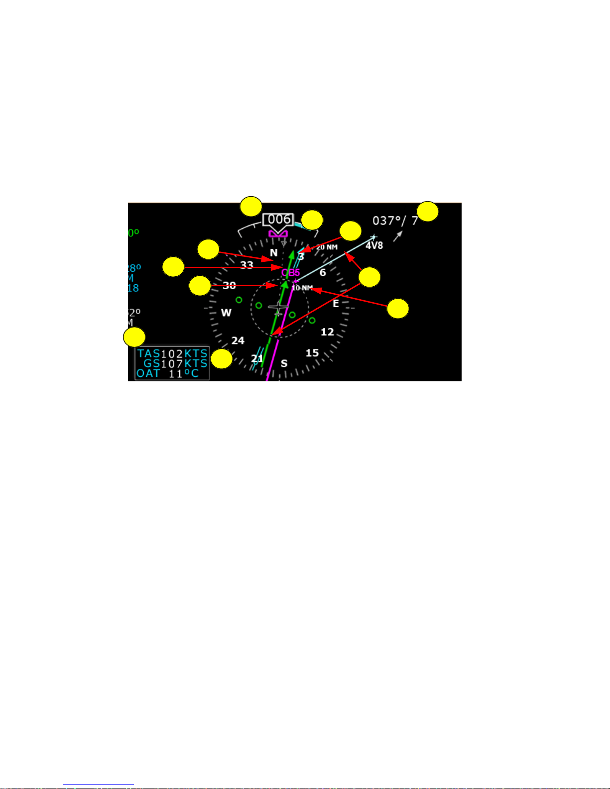
Figure 3. EHSI 360° View
1) Magnetic Heading—A numeric indication of current aircraft
magnetic heading.
2) Rate of Turn Indicator—The tip of the blue rate of turn indicator
displays the current rate of turn. The indicator is marked for 1/2
and full standard rate of turn. An arrowhead indicates a value
beyond 1 1/2 standard rate. For more information, see Using
Trend Indicators, on page 31.
3) Wind Vector—Displays the current wind speed and wind
direction. The arrow indicates the direction of the wind relative to
the current aircraft heading.
➥ After you turn, there will be a lag of several seconds in
updating current wind speed and direction.
1
10
6
11
4
5
2
3
7
8
9

EXP5000 Lower Half Display
600-00104-001 Rev 01 -13- Entegra EXP5000 PFD
The wind vector on the HSI is very useful in any phase of flight
where you need to take winds aloft into account. You can use a
combination of the wind vector and projected track line in
navigation tasks.
4) Projected Track Line—The dashed gray projected track line
originates from the aircraft present position symbol and
terminates at the triangle along the outer edge of the compass
rose. It displays a projection of the current ground track of the
aircraft.
➥ To take the guesswork out of determining proper crab angles
for wind corrections, align the projected track line with the
desired course.
5) Bearing Pointer—The blue dual-line bearing pointer is
associated with the Bearing source and displays the current
bearing to the Bearing waypoint (GPS 1 or GPS 2) or to the
station (VLOC 1 or VLOC 2). A bearing pointer does not display if
you tune the VLOC source to an ILS or LOC station.
6) Course Deviation Indicator (CDI)—The green single-line CDI
displays deviation from the set or desired course.
7) To-From Flag—The small green arrow indicates whether you are
heading to or from the current VOR or GPS waypoint. If you are
heading to the VOR, the arrow points the direction you are flying.
If from, the arrow points towards your most recent VOR or
waypoint.
8) HSI Moving Map—Displays up to a maximum of 15 waypoints
and labels from the active flight plan. The active leg of the flight
plan is depicted in magenta, and all other legs of the flight plan
are depicted in white. The moving map will also display waypoints
and labels of an approach and hold.
9) HSI Map Range—When the moving map is selected for display
on the HSI via the View knob, the outer and inner rings of the
Note: Under very light wind conditions or when wind speed cannot be
calculated, wind data will be replaced by dashes.
Note: In dual-PFD equipped aircraft, differences between the two wind
vectors during light winds are normal.
 Loading...