

Avidyne FlightMax EX5000 Pilot's Manual
600-00105-000 Rev 01

600-00105-000 Rev 01 -i- FlightMax EX5000
Revision History
Date
Revision Description
Dec 16, 2003
00 ECO 03-289
System Configuration
When contacting your dealer or Avidyne technical support, and when
logging onto www
.myavidyne.com for the first time, please have your
FlightMax EX5000 serial number and Subscriber Communicator serial
number available:
FlightMax EX5000 S/N_________________
Datalink Subscriber Communicator S/N_____________
Feb 17, 2004
01
ECO 04-024

FlightMax EX5000 -ii- 600-00105-000 Rev 01
Page Intentionally Left Blank.

Table of Contents
Introduction . . . . . . . . . . . . . . . . . . . . . . . . . . . . . . . . . . . . . .2
Operation . . . . . . . . . . . . . . . . . . . . . . . . . . . . . . . . . . . . . . . .3
Map Page . . . . . . . . . . . . . . . . . . . . . . . . . . . . . . . . . . . . . . . .4
Controls . . . . . . . . . . . . . . . . . . . . . . . . . . . . . . . . . . . . . . .4
Symbology . . . . . . . . . . . . . . . . . . . . . . . . . . . . . . . . . . . . .6
Map Orientation Control . . . . . . . . . . . . . . . . . . . . . . . . . .7
Using Datalink . . . . . . . . . . . . . . . . . . . . . . . . . . . . . . . . . .8
Trip Page . . . . . . . . . . . . . . . . . . . . . . . . . . . . . . . . . . . . . . . .10
Nearest Page . . . . . . . . . . . . . . . . . . . . . . . . . . . . . . . . . . . . .12
Engine Instruments . . . . . . . . . . . . . . . . . . . . . . . . . . . . . . .14
Gauges . . . . . . . . . . . . . . . . . . . . . . . . . . . . . . . . . . . . . .15
Fuel Usage . . . . . . . . . . . . . . . . . . . . . . . . . . . . . . . . . . .16
Temperatures . . . . . . . . . . . . . . . . . . . . . . . . . . . . . . . . . .17
Lean Assist . . . . . . . . . . . . . . . . . . . . . . . . . . . . . . . . . . .18
Data Blocks . . . . . . . . . . . . . . . . . . . . . . . . . . . . . . . . . . .22
Data logging . . . . . . . . . . . . . . . . . . . . . . . . . . . . . . . . . .23
Setup Pages . . . . . . . . . . . . . . . . . . . . . . . . . . . . . . . . . . . . .24
Main . . . . . . . . . . . . . . . . . . . . . . . . . . . . . . . . . . . . . . . . .24
Airport Filter . . . . . . . . . . . . . . . . . . . . . . . . . . . . . . . . . . .25
Declutter . . . . . . . . . . . . . . . . . . . . . . . . . . . . . . . . . . . . .26
Data Block Edit . . . . . . . . . . . . . . . . . . . . . . . . . . . . . . . .27
System Time . . . . . . . . . . . . . . . . . . . . . . . . . . . . . . . . . .28
Datalink Setup . . . . . . . . . . . . . . . . . . . . . . . . . . . . . . . . .29
Traffic Mode . . . . . . . . . . . . . . . . . . . . . . . . . . . . . . . . . . . . .30
Database Updates . . . . . . . . . . . . . . . . . . . . . . . . . . . . . . . .31
Appendix . . . . . . . . . . . . . . . . . . . . . . . . . . . . . . . . . . . . . . . .32
Sensor Status Block . . . . . . . . . . . . . . . . . . . . . . . . . . . .32
Symbols . . . . . . . . . . . . . . . . . . . . . . . . . . . . . . . . . . . . . .33
SUA and TFR Status . . . . . . . . . . . . . . . . . . . . . . . . . . . .35
Airmet and sigmet Boundaries . . . . . . . . . . . . . . . . . . . .35
Data Block . . . . . . . . . . . . . . . . . . . . . . . . . . . . . . . . . . . .36
System Messages . . . . . . . . . . . . . . . . . . . . . . . . . . . . . .38
Data Base Update Procedures . . . . . . . . . . . . . . . . . . . .43
Data Base Region Map . . . . . . . . . . . . . . . . . . . . . . . . . .43
Failure Indications . . . . . . . . . . . . . . . . . . . . . . . . . . . . . .44
Consult the Flight Manual Supplement (FMS) provided with the
aircraft and/or sensors prior to operation. The FMS contains
information specific to your installation and it may contain
operating limitations applicable to your aircraft configuration.
600-00105-000 Rev 01 -1- FlightMax EX5000
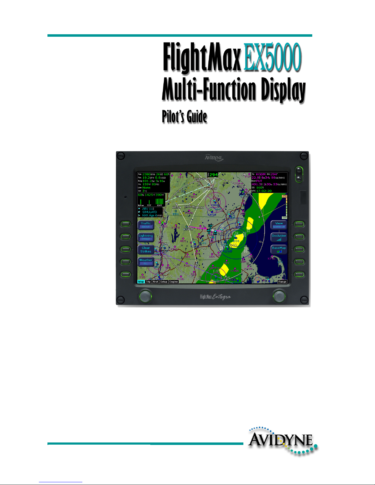
The FlightMax EX5000 Multi-Function Displays (MFD) provide a pictorial view of
your flight situation based on input from your GPS navigator. It utilizes on-board
database information for mapping off-route navigation data such as nearby airports,
VORs, NDBs, special-use and restricted airspace, etc., as well as terrain, interstate
highways, bodies of water, and obstacles.
The EX5000 uses RS-232 to interface to external sensors such as GPS, Goodrich
WX-500 Stormscope Sensor, and Ryan TCAD Traffic Sensor, if installed. The
EX5000 additionally offers ARINC 429 data bus capability. When interfaced via
ARINC 429 to a Garmin GNS 430/420-series GPS, the EX5000 will display the curved
paths associated with instrument approaches including DME arcs, holds, and
procedure turns. The EX5000 will also provide traffic display capability when
interfaced with the Goodrich Skywatch
®
traffic sensor, if installed.
FlightMax EX5000 -2- 600-00105-000 Rev 01
Introduction
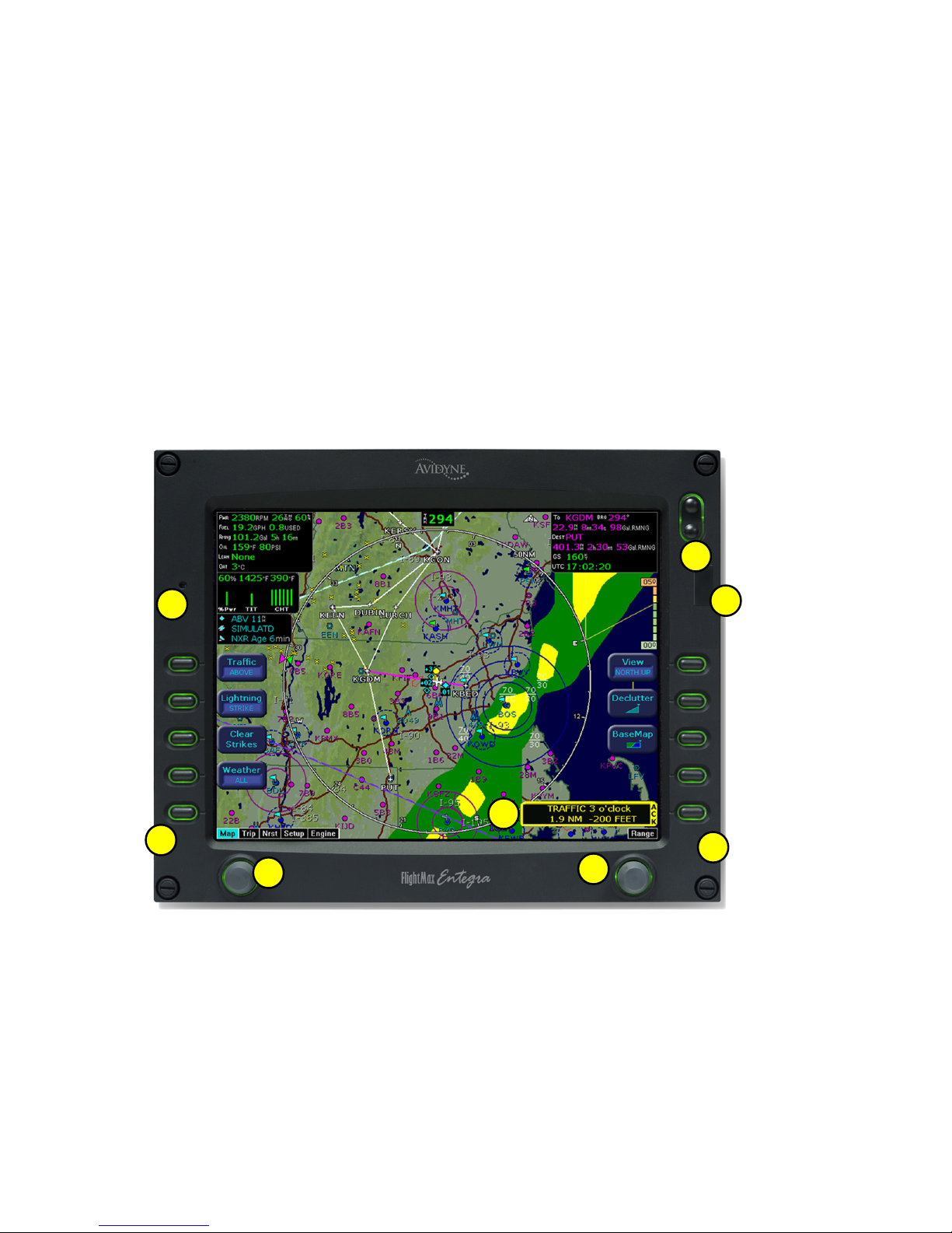
The controls on the bezel of the FlightMax EX5000 are placed to allow you quick and
intuitive access to the information you need, when you need it.
2
3
4
4
5
6
7
1

600-00105-000 Rev 01 -3- FlightMax EX5000
Operation
General
The EX5000 startup is automatic once power is applied. The system performs a brief
hardware self-test, then systematically initializes its functions. After the system has
been initialized (less than a minute after power-on), the title screen appears on the
system page. Database currency information is also presented. It is here that the pilot
is warned of any expired databases.
When the MFD is ready for use, the message “Press any bezel key to continue” is displayed.
Operational Controls
1) PhotoCell Light Sensor - Automatically compensates display brightness for
varying lighting conditions.
2) Brightness Control - Manually adjusts display brightness level.
3) Data Port - Provides a front panel access point for loading database updates and
downloading recorded engine data.
4) Buttons - Used to select modes or change the display as indicated. Active when
label appears on the screen adjacent to the key.
5) Page Control - Left knob provides quick access to the various MFD pages. The
current page is highlighted in the lower left corner of the screen.
6) Range & Cursor Control - Right knob controls the Map’s range. When other pages
are selected, the right knob provides item selection control.
7) Message Bar - The message bar is used to keep the pilot informed about critical and
advisory information from the MFD. When information needs to be conveyed the
message bar appears as the lowest right button.
The message bar can display only one message at a time. If more than one message
is available, the message bar will display the highest priority message on top. The key
associated with the Message must be depressed to clear messages and view those
underneath.
FlightMax EX5000 -4- 600-00105-000 Rev 01
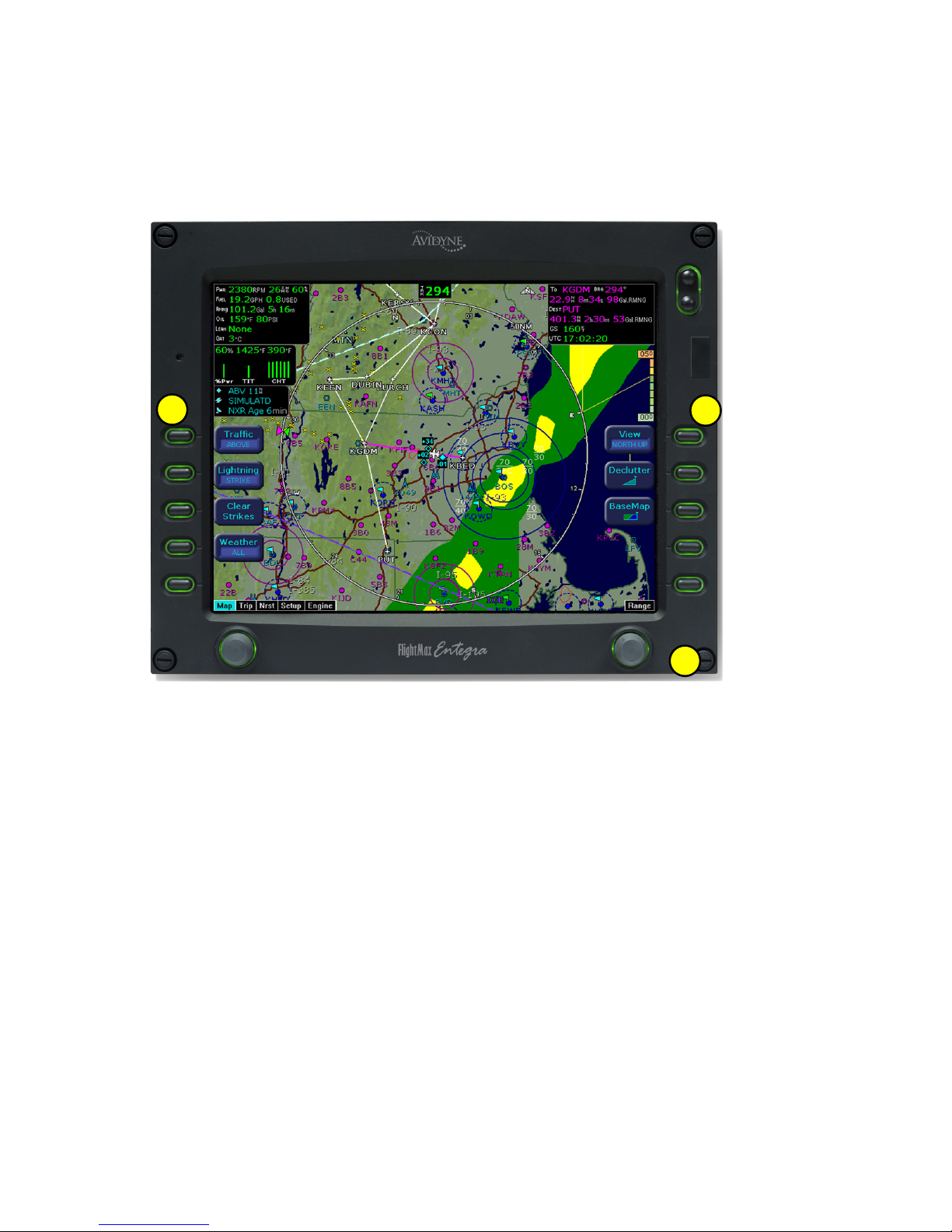
Map Page - Controls
Line select keys on the left side of the bezel provide access to sensor modes. Line
select keys on the right side of the bezel access the mapping functions, and control
how the Map is viewed.
1
2
3

1) Sensor Functions - Control overlay and modes of available sensors. Buttons are
only displayed for those sensors that are installed in the aircraft.
Traffic button with TAS (SkyWatch or BendixKing) cycles through traffic sensor
modes and overlay in the following order:
Above ->Normal ->Below ->Unlimited (UNLIMTD) ->Traffic Overlay Off (DSPLY OFF)
Traffic button, with Ryan TCAD, cycles through traffic sensor modes and overlays
based on the phase of flight as calculated from the TCAD. The modes are: Ground,
Terminal, Standard, Enroute, Unlimited, Approach, Departure and Display off.
Intruders are displayed as they are received from and identified by the sensor. The
threat level assigned to an intruder is the threat level specified by the sensor when it
transmits the intruder data. Threat data, range, bearing, altitude, ID, and closing
direction are defined by the sensor and the type of sensor used in your system.
Lightning button cycles through lightning sensor modes and overlay in the
following order: Strike ->Cell ->Lightning Overlay Off (DSPLY OFF)
The lightning sensor maps thunderstorm activity by monitoring electrical discharge
activity within a 200-mile radius of the aircraft. Lightning strikes less than 25NM
distant are not displayed if the display range is set to less than 25NM. If the display
range is set to greater than 25NM, all lightning strikes will be displayed.
Clear Strikes button removes lightning symbols to allow for the refresh of
lightning data.
Weather button cycles through Datalink weather modes and overlay based on the
Datalink data requested from the Datalink Setup Page. With all data requested, the
order is: ALL (Nexrad, METARS and Airmets) ->REPORTS (METARS and Airmets)
-> NEXRAD -> Datalink Weather Display Off.
2) Map Functions - Control basic look of the map in terms of orientation, number of
elements, and base map.
View line select key orients the map for either Track/Heading Up or North Up.
FORWARD view orients the map with Track/Heading Up and the aircraft symbol at
the bottom of the screen. CENTER view orients the map with Track/Heading Up and
the aircraft symbol centered on the screen. NORTH UP orients the map with North
Up.
Declutter line select key allows you to quickly choose from four levels of database
Nav Map detail from most to least:
Base Map line select key selects from three levels of map detail, starting with
contoured terrain with interstate highways, water base map, and political
boundaries. Pressing the key removes contoured terrain with Interstates, while
leaving water and political boundary references. Push again to view the flight plan
on a traditional EFIS-style black background.
3) Range Control - Controls the map’s range and allows you to range down to 1NM
scale and out to 1500NM scale. The nineteen selectable ranges are 1, 2, 5, 10, 15,
20, 30, 40, 50, 75, 100, 150, 200, 300, 400, 500, 750, 1000, 1500.
(Note: Terrain base map is automatically removed and Nav database information is
fully decluttered at 750NM and higher ranges).
Map Page - Controls
600-00105-000 Rev 01 -5- FlightMax EX5000
200’ AGL to <1000’AGL
1000’ AGL or higher
Groups of obstacles
within 1NM of each other
Groups of obstacles 1000’ AGL or
higher and within 1NM of each other.
FlightMax EX5000 -6- 600-00105-000 Rev 01
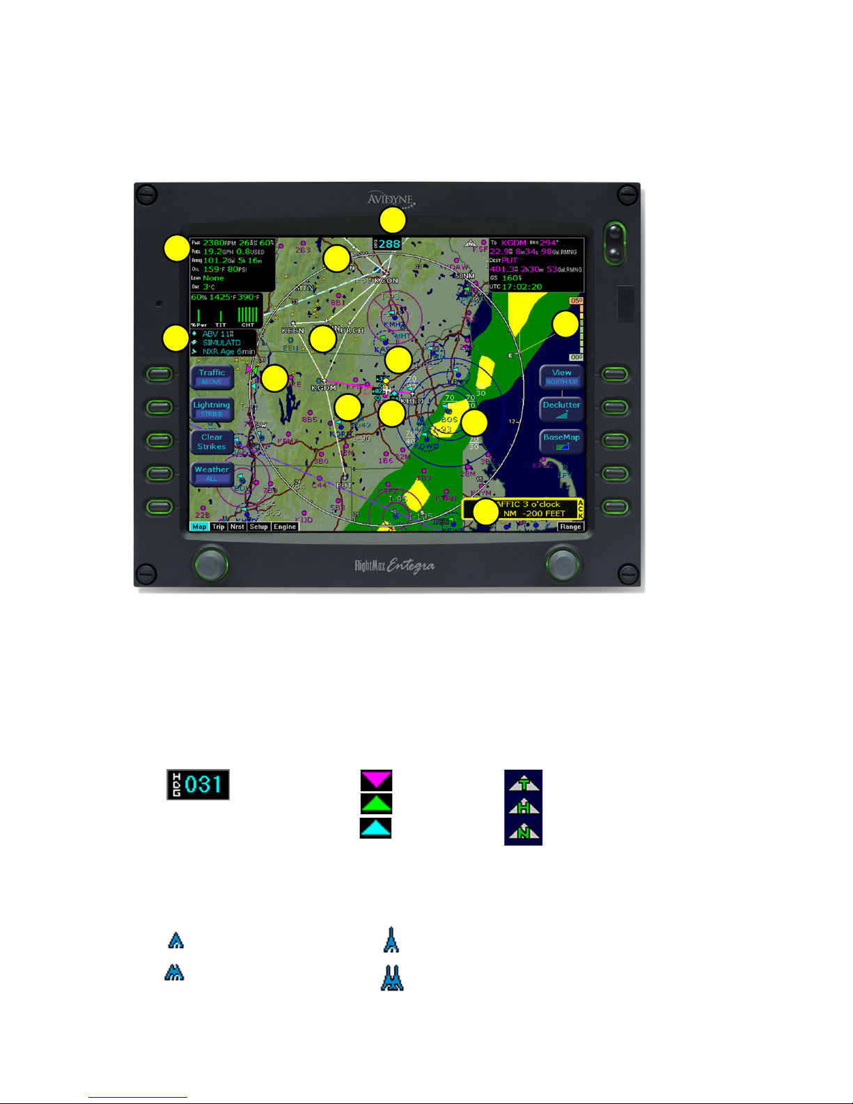
Map Page - Symbology
Heading Up
Track Up
1) Data Blocks (Left & Right) - View navigation and engine data in data blocks in the
upper corners of the display. See Data Block Edit (page 27) for options.
2) Sensor Status Box - Displays Nexrad data status and age, and the status of traffic
and lightning sensors, if installed.
3) Heading/Track Indicator - Three triangles around the compass rose provide actual
track, desired track, and heading indications. The H/T Block provides digital readout of
the current heading, or actual track. Map orientation is indicated in the triangle to the
right of the H/T Block.
Desired Track
H/T Block
Actual Track
Heading
North Up
The MFD’s map presentation depicts your aircraft’s position in relation to flight plan,
nearby airports, terrain, traffic, lightning, weather, special use airspace, and other
navaids.
1
2
3
4
5
6
7
8
9
10
11
12
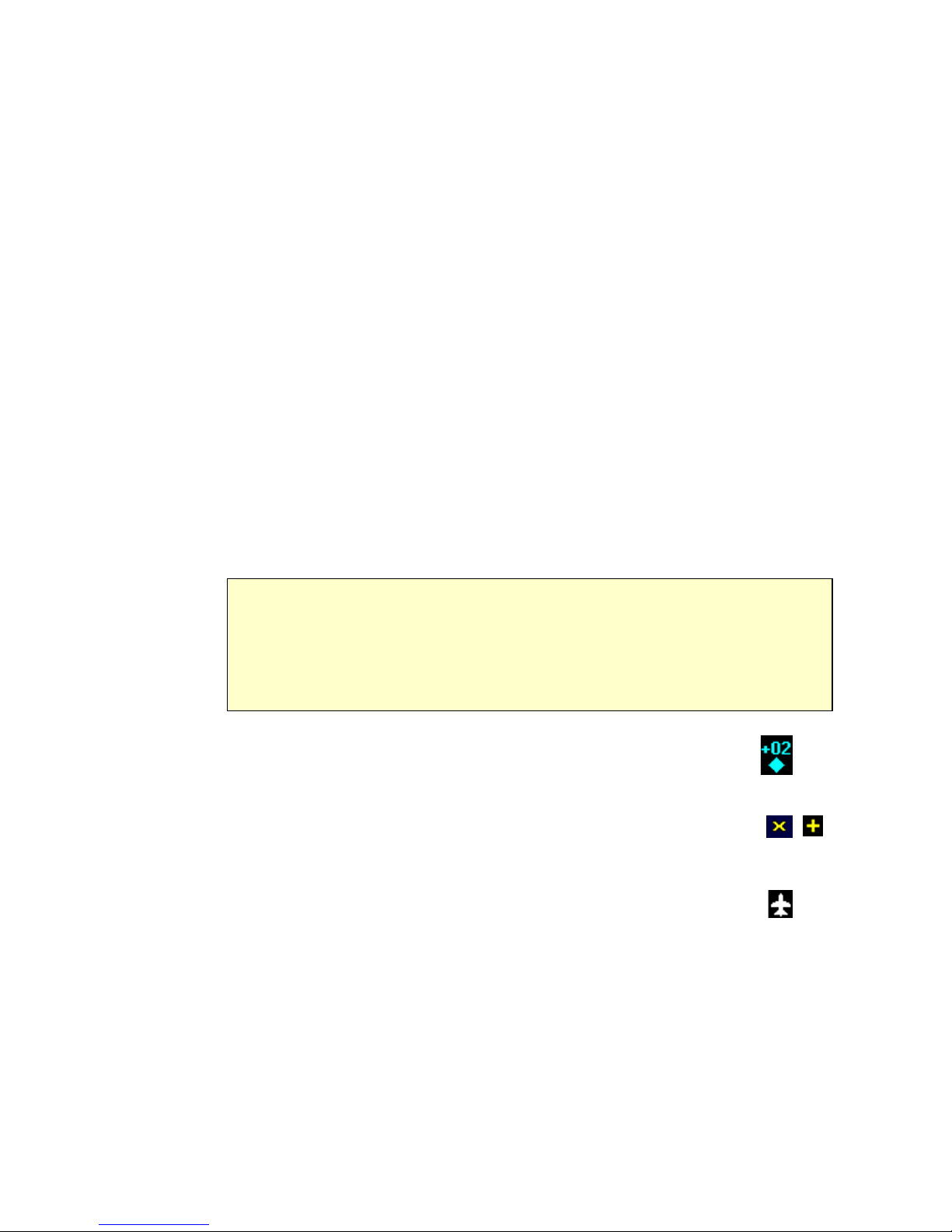
4) Obstacles - The MFD’s database contains towers and other obstacles greater than
200 feet AGL. Obstacles can be displayed with MSL altitude label. Symbols for
Obstacles:
5) Compass Rose/Range Ring - Displays a 360-degree or 120-degree compass
circle or arc and also indicates current range setting. The range number is the distance
from the airplane symbol to the compass arc.
6) Terrain Scale - Shows highest and lowest limits of terrain in displayed area. Legend
colors in between these numerics represent terrain elevations. Blue obstacle clearance
number shows the top of the highest obstacle, when greater than the highest displayed terrain.
Terrain data is not displayed when your aircraft’s latitude is greater than 75 degrees (north or
south).
7) Special Use Airspace - The MFD uses several different line styles to convey special use
and class airspaces. Class B is solid blue line, Class C is solid magenta line. Class D is
dashed blue line, MOA, Warning, and Alert areas are solid yellow lines, and restricted and
prohibited areas are solid red lines. Reference Table 5 and associated note (Page 35).
8) Airport Runway Diagrams - Runway layouts of your destination airport and nearby
airports are displayed. As you range in, the scaled runway diagram with heading labels
shows your exact location in proximity to the field.
9) Flight Plan - The active flight plan from the GPS is displayed on the map. The
current leg is displayed in magenta and all remaining legs are shown in white. When you
select an approach procedure on the Garmin 430, all approach segments including holds,
DME arcs, procedure turns, etc., are shown
10) Traffic Indications - Shows traffic symbol relative to current position and
includes relative altitude (when available) with respect to airplane symbol.
See traffic sensor user’s manual for further details.
11) Lightning Indications - Shows lightning strikes geographically referenced if
configured. Strikes represented by yellow “X” in Strike Mode, and by
yellow “+” in Cell Mode. Lightning strikes are displayed for three minutes.
12) Airplane Symbol - Shows the position of your aircraft in relation to the
moving map and the selected view.
600-00105-000 Rev 01 -7- FlightMax EX5000
Map Page - Symbology
Map Orientation Control
The pilot can control the orientation of the map and sensor data displayed on the
MFD with the Map View button. MFD traffic and lightning symbols are positioned
relative to the aircraft symbol nose. When the Map View is North-Up extra pilot
effort may be needed to locate traffic outside the aircraft. Set Map View to Center
or Forward to display this data consistent with typical dedicated traffic and lightning
sensor displays.
NOTE: The Garmin GNS 430/GNC 420 does not differentiate curved flight path segments
from straight segments when interfaced with the MFD via an RS232 interface. Therefore,
the MFD will connect the beginning and end waypoints of a curved segment, such as a
DME arc, with a straight line. Under these circumstances, the straight line must be
ignored. Approach procedures should be flown using the GNS 430/GNC 420 navigator’s
CDI as the primary reference. Consult your avionics installation facility to determine if your
MFD is interfaced to the GNS 430/GNC420 via ARINC 429 or RS232.
FlightMax EX5000 -8- 600-00105-000 Rev 01
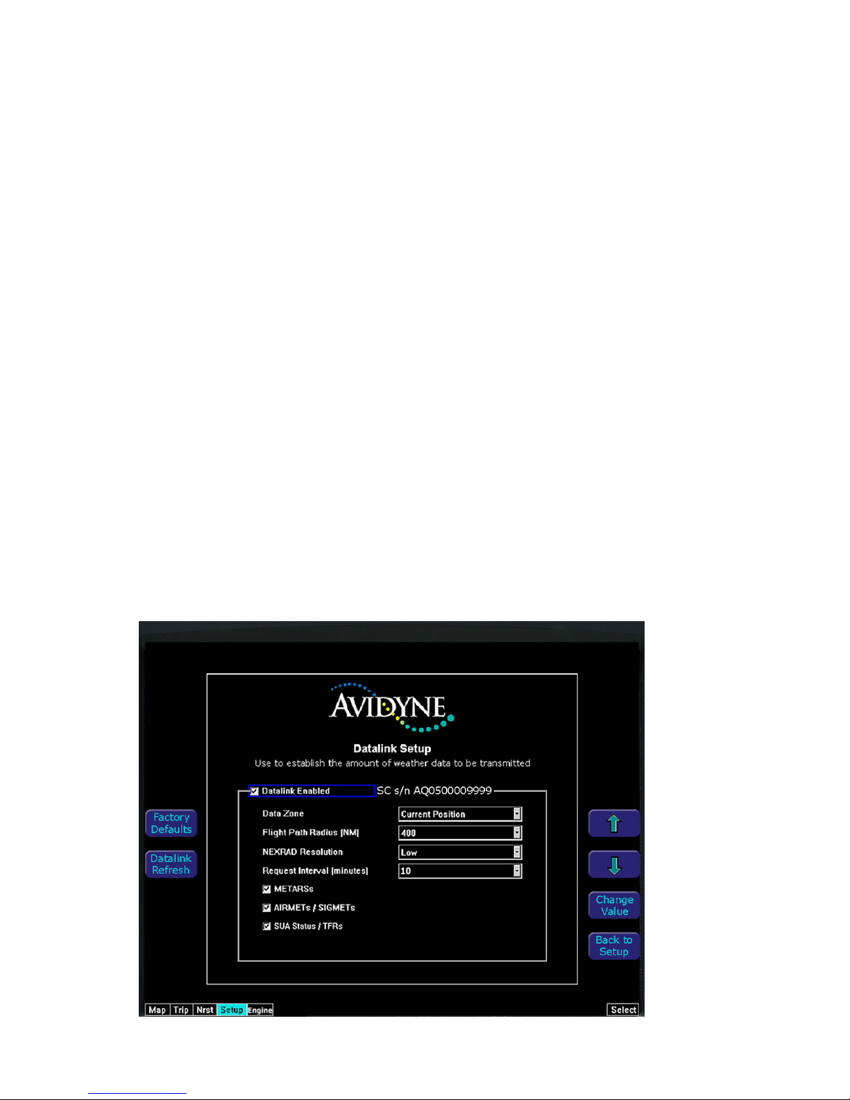
Your EX5000 comes equipped with an integrated datalink function that allows you to
stay completely tuned in to the current weather, SUA, and TFR conditions along your
route of flight. Since this function is completely integrated, there is nothing "special" or
new that you need to learn to make it work for you.
You will need to log on to MyAvidyne.com and follow the simple account setup
instructions in order to establish an Avidyne datalink account. Be sure to have your
datalink subscriber communicator (SC) serial number handy. You will need it to open
your account. You can view your SC s/n on the EX5000 Datalink Setup Page. Once
your account is activated, you may immediately begin enjoying the advantages of the
EX5000’s satellite-based datalink capability. In addition, your MyAvidyne.com datalink
account provides you with access to your billing and usage statements, as well as
providing pre-flight weather links and planning tools. You can set your datalink user
preferences online prior to your flight, and they will be downlinked to your EX5000 via
satellite the next time you fly.
When you power the EX5000 up, it will immediately begin sending position data to tell the
satellite network where you are and that you are about to begin a flight. Weather data will
begin transferring to your airplane based upon your user preferences. No action is
required to begin receiving weather (You will have to pull your airplane out of the hangar so
that the satellite receiver can interrogate and locate a satellite).
Upon entry of a flight plan into your primary GPS receiver, your EX5000 will
automatically download the weather for your route of flight without any additional action
required. Additional updates will be provided while enroute based upon the update rate
that you have selected online or on the EX5000’s datalink setup page.
Using Datalink
600-00105-000 Rev 01 -9- FlightMax EX5000
Using Datalink
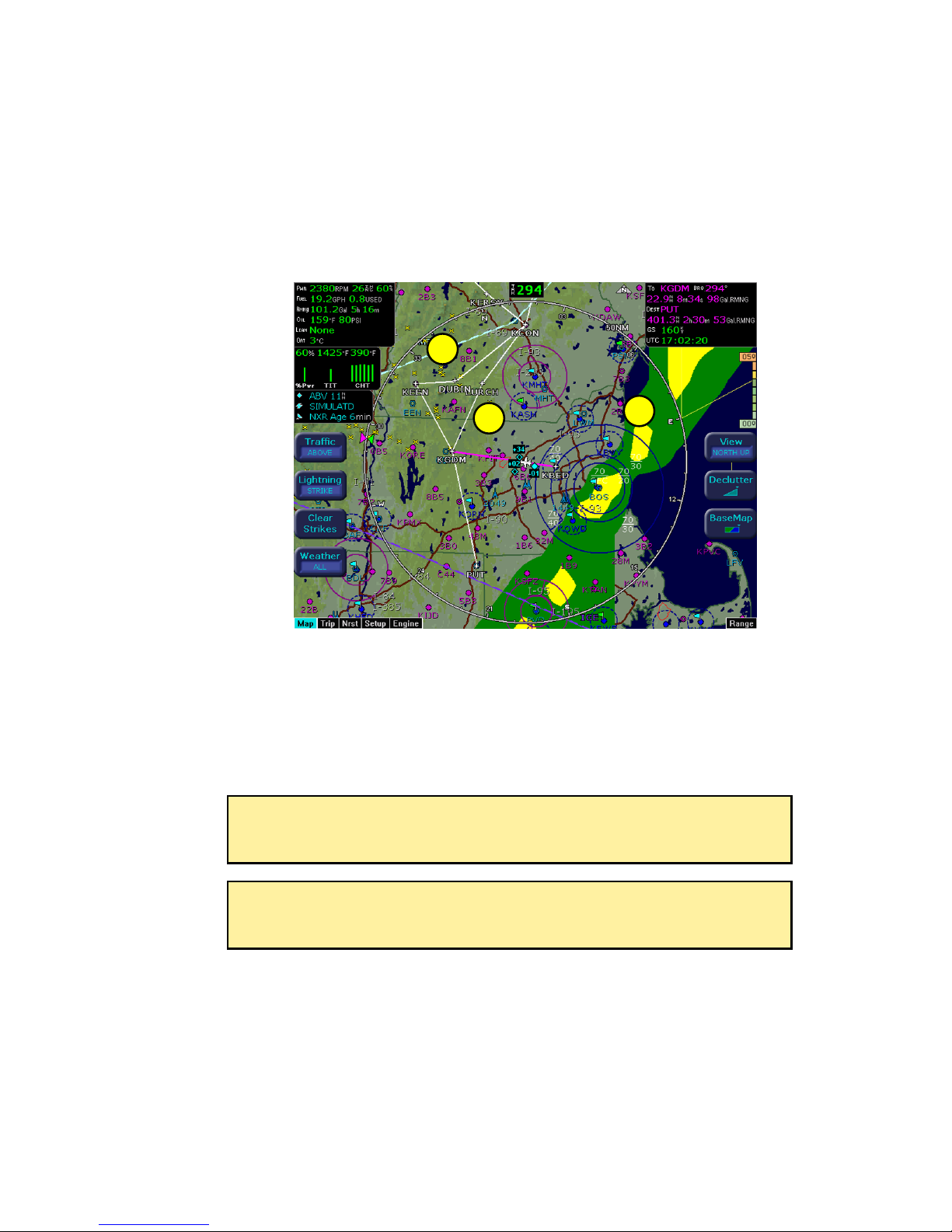
The Weather Overlay button allows you to add Nexrad Graphical METARs and Airmets
weather images onto the map display.
1) NEXRAD data is displayed in a four-color format consistent with weather radar
data. The NEXRAD age is displayed in the sensor status box. The displayed age
is calculated based on the time the national NEXRAD composite image is created.
The actual radar data may be slightly older than the displayed NEXRAD age. A legend for the NEXRAD display is available on the trip page.
2) Graphical METARS are displayed as small upright flags. These offer you a chance to
look at the "bigger picture" for weather along your route of flight. A legend for the
graphical METARS is available on the Trip Page.
3) Airmet/Sigmet data is overlaid with lines that alternate between single and triple thick.
The thick side of the line indicates the inside of the affected region. The regions are
labeled according to the type of Airmet/Sigmet, and the label is located in the interior
of the depicted region. (see Table 6)
The boundary of the available weather coverage area is shown by hash marks. The
intent of the datalink weather boundary is to clearly show when there is actual weather
in the area, versus when there may be weather in a given area but it is not displayed.
If you would like to expand the amount of data displayed (and therefore move the
boundary farther from your flight plan) you can do this on the Datalink Setup Page or
at MyAvidyne.com.
NOTE: The National Weather Service only provides NEXRAD for the
Continental United States (CONUS). The EX5000 will not depict NEXRAD
images for areas outside of CONUS.
CAUTION: Datalink weather should only be used for strategic planning purposes. Datalink weather should not be used for tactical weather avoidance.
Local conditions may have changed since your last weather update.
1
2
3
FlightMax EX5000 -10- 600-00105-000 Rev 01
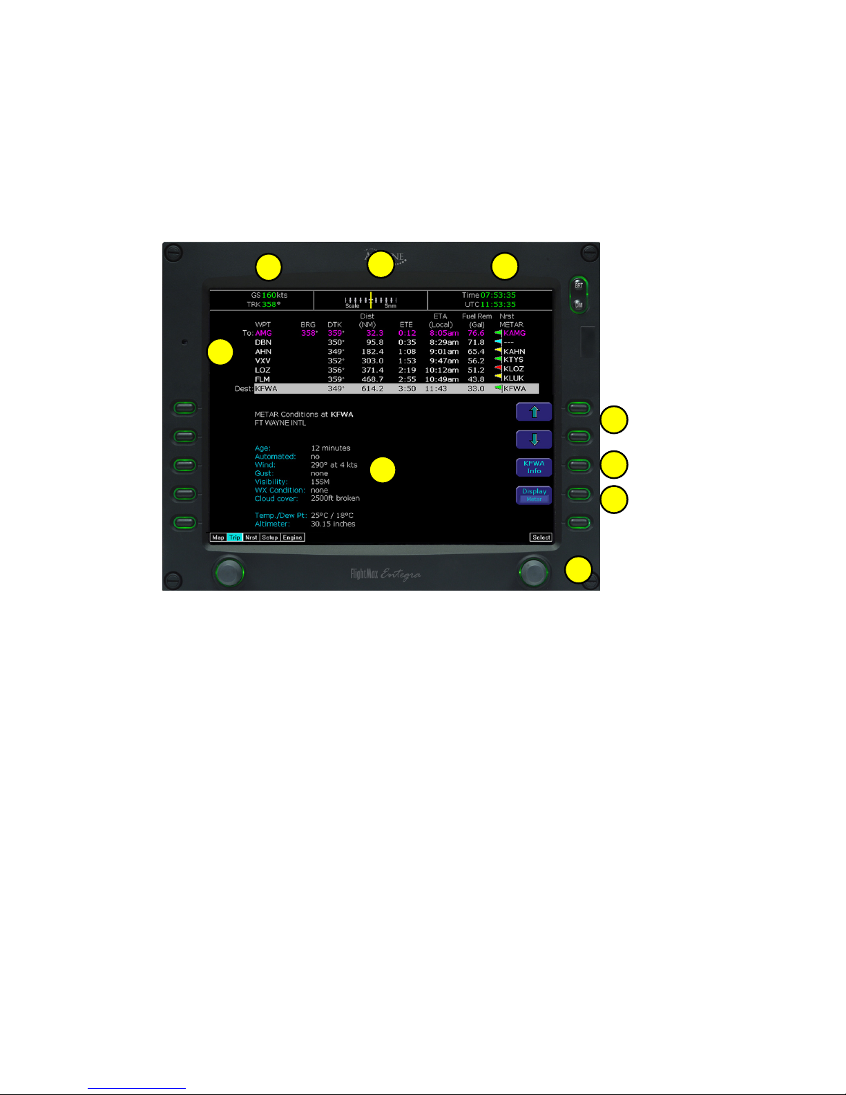
Trip Page
The Trip Page is continuously updated during flight. The distance and the time
values are updated with each new positive fix from the GPS. The route legs
advance with each waypoint message. Turning the left knob one detent to the right
from the Map page brings up the Trip Page, which shows the remaining legs in the
current flight plan and other data being received by the MFD from the GPS. If the
flight plan doesn’t fit on the screen, an ellipse (...) is shown in the next to last line.
The destination is always displayed, on the last line. A “No Flightplan Available”
message is displayed if there is no flight plan entered or if the GPS has failed.
1
2
3
4
5
6
8
9
7
1) Current ground speed and track
2) Flight Plan information from your GPS. Active waypoint is shown in magenta.
Displayed data:
WPT - Waypoint identifier as received from the GPS
BRG - Bearing to current waypoint
DTK - Desired track to waypoint
DIST (NM) - Cumulative great circle distance of each flight plan leg
ETE - Cumulative estimated time en route to waypoint in H:MM format
for each flight plan leg at current ground speed.
ETA - Estimated time of arrival to waypoint in HH:MM formatted for
airplane local time.
Fuel Remaining - Available with Engine and Fuel Monitor function.
Displays remaining fuel at each waypoint in gallons.
Nrst METAR - Available with Datalink enabled. Displays Graphical METAR
and reporting point identifier.
When conducting a Direct To flight plan, the MFD will supply METAR information for
several intermediate reporting stations along your route. These will be shown as
blank lines on the flight plan list, with "Wx" in the first column, and the METAR flag in
its normal position in the right column. Selecting one of the intermediate points will
display the text METAR on the lower half of the screen. The intermediate METAR
stations will be removed from the list as you pass them during your flight.
3) Course Deviation Indicator (CDI) - Shows lateral distance (Crosstrack deviation)
from desired course, providing continuous navigation reference when viewing the
Trip page.
4) Local and UTC time in HH:MM:SS using a 24-hour clock format.
5) Destination Airport Information - Provides quick access to airport information for
the destination airport, when available.
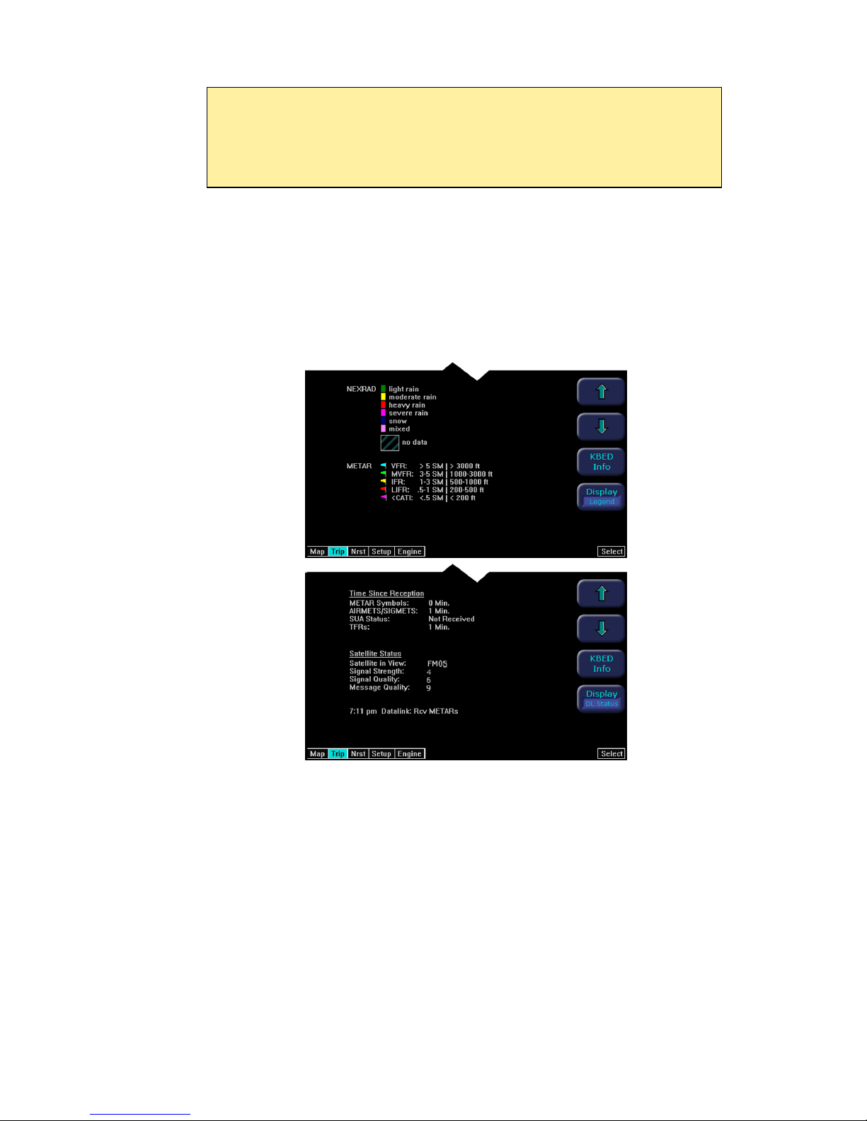
6 ) Display Button - By pressing the adjacent button, you can toggle through Textual
METARS, NEXRAD/METAR Legend, and Datalink Status. The Satellite Status
values have been normalized to values between 0 and 10 to allow easy
determination of the satellite link.
Satellite in View - Displays the name of the satellite the system is currently using.
Signal Strength/Signal Quality - Signal Status represents the overall health of the
satellite signal. The higher these value are, the better the signal strength. You should
normally see values between 4 and 10.
Message Quality - Even when the signal strength is good, messages may be dropped if
the local interference level is too high. You should see values between 7 and 10 during
normal operation.
7) Text METAR - The translated METAR is displayed for the selected flight plan waypoint.
Note that if the selected waypoint is not reporting weather, the METAR information will
be reported from the nearest METAR station.
8) Select Knob - Moves the cursor over the desired waypoint in the flight plan, which
selects the plain-English textual METAR to be displayed along the bottom half of
the screen.
9) Select Buttons - These buttons can be used instead of right knob to move cursor
600-00105-000 Rev 01 -11- FlightMax EX5000
Trip Page
NOTE: When the MFD is interfaced to a Garmin GNS-430/GNC-420 via
RS-232, the GPS may send duplicate waypoints while in approach mode. These
duplicate waypoints may affect the distance and time readings on the trip page.
Approach procedures should be flown using the GPS as the primary source of
navigation information. Consult your avionics installation facility to determine if your
MFD is interfaced to the Garmin GNS-430/GNC-420 via ARINC 429 or RS-232.
FlightMax EX5000 -12- 600-00105-000 Rev 01
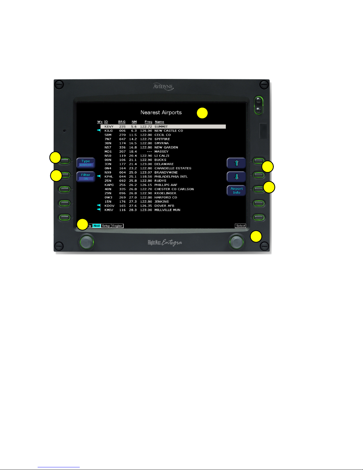
Nearest Page (NRST)
From the Trip page, turning the left knob one detent to the right brings up the NRST
Page. The Nearest Page brings up the nearest airports within 60NM of your present
position. Through the line select keys, you will also have access to detailed
information about each airport. The line select keys also allow you to view the nearest
VORs, NDBs, Intersections, and Obstacles.
5
1
3
2
4
3
6
 Loading...