

Avidyne FlightMax EX500 Pilot's Manual
600-00078-000 Rev 09
Multi-Function Display
Pilot’s Guide


600-00078-000 Rev 09 -i- FlightMax EX500
Document Review History
This document is applicable to Software Part Number 530-00193-000
and Hardware Part Numbers 700-00007-().
All materials copyrighted including images that represent this
software Copyright 2007 Avidyne Corporation. All rights reserved.
System Configuration
Date Revision Description
12/13/02 00 Initial Release per ECO 02-363
1/30/03 01 Revised per ECO 03-038
2/10/03 02 Revised per ECO 03-056
3/10/03 03 Revised per ECO 03-076
01/07/05 04 Revised per ECO 04-215
04/07/05 05 Revised per ECO 05-065
04/14/05 06 Revised per ECO 05-062
05/15/07 07 Revised per ECO-07-112
07/05/07 08 Revised per ECO-07-211
04/15/08 09 Revised per ECO-07-477
When contacting your dealer, Avidyne technical support, or logging
onto MyAvidyne.com for the first time, please have your FlightMax
EX500 serial number and Subscriber Communicator serial number
available:
FlightMax EX500 S/N: _________________________________
Datalink Subscriber Communicator S/N: ___________________
FlightMax EX500 -ii- 600-00078-000 Rev 09
About This Guide
This guide describes the EX500 with all available sensors and
software options installed. Therefore, the EX500 page layouts and
button descriptions in this guide may differ from those on your EX500
display.
The standard EX500 version and the radar-capable EX500 differ in
the number of function knobs.
● The standard EX500 has two knobs: a Page knob and a Range
knob.
● The radar-capable EX500 has four knobs, two on the left of the
display and two on the right. The right-hand knobs are usually
used for Page and Range, the left-hand knobs provide dedicated
radar Bearing and Tilt control, along with other functionality,
depending on the Page being viewed.
See Starting the EX500 on page 2 for descriptions of the knobs and
their functions. The EX500 examples shown in this manual use the
four-knob radar version.
Notes and Warnings
Notes and Warnings provide guidance for the use of the EX500.
Avidyne strongly suggests that you read all Notes and Warnings for
your own safety.
For example:
Note: Notes provide useful information about how to use the EX500.
The instructions and warnings in this manual, however, are not
intended to replace the instructions and warnings for other equipment
on your aircraft. It is critical that as the pilot in command, you have a
complete understanding of the warnings, operating instructions, and
limitations for all equipment installed on your aircraft.
!
Warnings are prefaced with exclamation points and denote
information that can prevent serious injury or death on the part
of the user.
600-00078-000 Rev 09 -iii- FlightMax EX500
!
This manual assumes that the reader is an appropriately
licensed pilot. Avidyne strongly recommends that you use the
EX500 only under VFR conditions until you are very familiar
with the EX500.
If you have questions, please contact Avidyne at 800-284-
3963 (800-AVIDYNE) or 1-781-402-7400
before operating
with the EX500 under IFR conditions.
!
Before conducting flight operations, be sure to verify that time
and date settings on the System Time Setup Page are correct
and in GMT (UTC). It is critical that the time be set to GMT to
provide accurate display of Datalink weather. See
Chapter 9 "Aux Page for more information.
FlightMax EX500 -iv- 600-00078-000 Rev 09
!
Notice regarding NOTAM information
NOTAM information is subject to constant change, and it is
extremely important that all pilots check with Flight Service for
applicable NOTAMs prior to EVERY flight. Call 1-800WXBRIEF (992-7433) for the latest information. Outside the
United States, call your local flight service or other official flight
advisory service.
The NOTAM information provided by the EX500 is for
planning purposes only. Always consult official NOTAMS for
the latest restrictions.
Avidyne does not provide a complete list of NOTAMS. Local
NOTAMS, most laser light NOTAMS, and any NOTAMS other
than restricted airspace are not listed.
By using the Avidyne Services you are able to access
information made available from a variety of sources. Avidyne
does not control, edit or review the content of such information
and is not responsible for such information or the actions or
conduct of any company that provides sources of weather
data procured by Avidyne. Therefore, although Avidyne uses
diligent efforts to provide Services of high quality, ALL
SERVICES AND WEATHER DATA ARE PROVIDED AS-IS
and neither Avidyne nor its suppliers (including ORBCOMM
and its affiliates), subcontractors, information sources or
developers (collectively called “Suppliers”) are responsible for:
1) the accuracy, completeness, timeliness, reliability, content,
or availability of the Services or any information accessed; 2)
loss or damage to your records or data; or 3) your use of, or
results achieved from, the Services or any information
accessed.
!
Certain GPS navigators do not support transmission of curved
flight path segments (e.g. DME arcs). These units include:
KLN-89B/90B/94
- Flight plan ends at entry point to arc.
Trimble 2000, 2101
- Sends multiple waypoints around arc.
Garmin 400/500 series
- RS-232 displays a straight line.
Bendix/King GNS-XLS
- Arc is depicted as a gap.

600-00078-000 Rev 09 -v- FlightMax EX500
Copyrights and Trademarks
Charts shown in the CMax™ section of this manual are copyright protected
by Jeppesen Sanderson, Inc. All trademarks and trade names are the
property of their respective owners.
Note: The navigation data for the EX500 includes copyrighted data
compilations owned by Jeppesen Sanderson, Inc. Avidyne
has been granted a limited, non-exclusive license for their
use. The copyrighted subject matter may be used only in
connection with the ordinary and intended use of the EX500
as described in this manual. Its use for any other purpose, or
reproduction or copying of any portion of said copyrighted
subject matter, is strictly prohibited.
All materials are copyrighted including images that represent this software.
Copyright 2008 Avidyne Corporation. All rights reserved.
AVIDYNE FLIGHTMAX EXCLUSIVE LIMITED WARRANTY/
LIMITATIONS ON LIABILITY
Avidyne warrants the Product manufactured by it against defects in material and workmanship
for a period of twenty-four (24) months from delivery. If Avidyne's Product fails to conform to
this warranty, Avidyne, in its sole discretion, will either repair or replace the Product or provide
a refund of the purchase price paid for the Product. This warranty is made upon the express
conditions that:
(a) Avidyne is given prompt written notice of any claimed non-conformity in the Product, with a
reasonable explanation thereof;
(b) The Product is returned to Avidyne or to an Avidyne authorized service facility;
(c) The Product has not been altered in any manner other than as previously authorized by
Avidyne in writing; and
(d) Repairs to the Product have not been made by anyone other than Avidyne or an Avidyne
authorized service facility.
This warranty does not apply to any Product which is not installed, maintained and operated in
accordance with Avidyne's written instructions or which is otherwise misused, including,
without limitation, to any Product which is damaged due to improper installation, maintenance
or operation, tampering, alteration of serial numbers or other manufacturers data, lightning or
other electrical source, or otherwise.
If warranty protection is applicable to the Product, Avidyne will use reasonable efforts to repair
or replace Product within ten (10) business days of its receipt of the Product.
Any Product that has been repaired by Avidyne or replaced by Avidyne under this warranty will
be subject to remainder of the original warranty term applicable to the repaired or replaced

FlightMax EX500 -vi- 600-00078-000 Rev 09
Product or will be warranted under the warranty terms above for ninety days from the date of
repair or replacement, whichever period is longer.
This exclusive limited warranty applies in lieu of and expressly supersedes and excludes all
other representations, affirmations and/or warranties, whether express or implied, oral or
written, including, without limitation, any warranty of merchantability, of fitness for a particular
purpose, of title and/or of non-infringement. purchaser expressly and knowingly agrees that no
other representations, affirmations or warranties, whether express or implied, oral or written,
form part of any purchase and sale transaction related to the product.
Avidyne's (and its affiliates') and any product component supplier's sole responsibility and
liability related to the product or arising out of or related to its purchase, sale, performance,
reliability or use are limited to its repair or replacement, or to a refund of the purchase price, in
Avidyne sole discretion. in no event will Avidyne (or its affiliates) or any suppliers of product
components be responsible or liable for any other damage of any nature whatsoever, including
direct, indirect, incidental, consequential, special, loss of use, loss of revenue or profit,
property damage, personal injury, wrongful death, or other damage (whether or not Avidyne
(or its affiliates) were notified of the possibility that any damage might be incurred), arising out
of or related to the product, its purchase or sale, its performance or reliability, or the use or
inability to use the product, for any reason, including due to any product defect or defects or
any action or inaction of any nature (including claimed or actual negligence or gross
negligence) by Avidyne or any suppliers of product components. neither this exclusive limited
warranty nor Avidyne's or any product component supplier's responsibility or liability will in any
way be enlarged or otherwise altered due to Avidyne's provision of technical support or
training related to the product.
Without limiting the foregoing, neither Avidyne (nor its affiliates) make any representations,
affirmations or warranties regarding or related to products not manufactured by Avidyne or
regarding or related to the performance or reliability of any such product, either alone or when
used with any product manufactured by Avidyne, or the suitability of any such product for use
with any product manufactured by Avidyne. Avidyne (and its affiliates) expressly disclaim any
and all representations, affirmations and/or warranties regarding or related to any such
products. in no event will Avidyne (or its affiliates) be responsible or liable for any damage of
any nature whatsoever, including direct, indirect, incidental, consequential, special, loss of
use, loss of revenue or profit, property damage, personal injury, wrongful death, or other
damage (whether or not Avidyne (or its affiliates) were notified of the possibility that any
damage might be incurred), arising out of or related to products not manufactured by Avidyne,
the purchase or sale of such products, their performance or reliability, either alone or when
used with any product manufactured by Avidyne, or the suitability of any such product for use
with any product manufactured by Avidyne.
This exclusive limited warranty also applies in lieu of and expressly supersedes and excludes
all other rights any purchaser has or may have related to the product and/or arising out of or
related to its purchase, sale, performance, reliability or use, either alone or with any other
product or products, whether in contract, in tort (including rights sounding in negligence, strict
liability and misrepresentation), under statute, at law, in equity, or otherwise, and purchaser
expressly and knowingly waives all such rights to the fullest extent permitted by law. purchaser
also expressly and knowingly agrees that the product is not a consumer good.

600-00078-000 Rev 09 -vii- FlightMax EX500
The foregoing four paragraphs define and limit Avidyne's sole responsibility and liability and
purchaser's sole and exclusive remedies related to the product.
Some jurisdictions may not allow the exclusion or limitation of warranties or liabilities, in which
case the above limitations or exclusions, or some of them, may not apply in those jurisdictions

FlightMax EX500 -viii- 600-00078-000 Rev 09
This page intentionally left blank.

600-00078-000 Rev 09 -ix- FlightMax EX500
Contents
1 Introduction.............................................................. 1
Starting the EX500 ...................................................................... 2
2-Knob and 4-Knob Functionality ................................................ 5
2 Map Page .................................................................. 7
Map Page Controls...................................................................... 7
Map Page Symbols—Terrain and Position................................ 12
Map Page Symbols - Runways and Flight Plan ........................ 16
Errors Displayed on the Map Page............................................ 18
Loss of GPS Input ............................................................... 18
Loss of Heading Input ......................................................... 18
3 Traffic Mode and the Traffic Page (Optional) ...... 19
Traffic Advisories ....................................................................... 20
The Traffic Page ........................................................................ 21
Traffic Symbols.......................................................................... 23
TIS Sensor Status ..................................................................... 24
4 Radar Page (Optional) ........................................... 25
Map Page Overlay..................................................................... 26
Dedicated Radar Page .............................................................. 28
Dedicated Radar in Ground Mode............................................. 31
Typical Radar ............................................................................ 33
Vertical Profile Mode ................................................................. 34
Radar Warnings......................................................................... 36
5 TAWS Page (Optional)........................................... 37
TAWS Information ..................................................................... 37
TAWS Operation ....................................................................... 41
TAWS Reference....................................................................... 43
Auto-Range ......................................................................... 43
Simultaneous Alerts ............................................................ 43
Terrain Messages and Error Indications ............................. 43
6 CMax Chart Pages (Optional) ............................... 45
About Geo-Referenced Charts .................................................. 45
CMax Chart Page ...................................................................... 46
CMax Procedure Charts...................................................... 47
CMax Chart Views..................................................................... 50
Procedure Views ................................................................. 50
Airport Chart Views ............................................................. 52
Selecting an Airport ................................................................... 54

FlightMax EX500 -x- 600-00078-000 Rev 09
Selecting a Chart .................................................................56
Chart NOTAMs Page .................................................................58
7 Trip Page................................................................. 59
About the Trip Page ...................................................................59
Trip Page Information ................................................................60
Airport Information Page ............................................................66
8 Nearest Page (NRST) ............................................. 67
Nearest Page .............................................................................67
Airport Information Page ............................................................69
9 Aux Page................................................................. 71
Aux Main Page...........................................................................71
Airport Filter Setup .....................................................................73
Declutter Setup ..........................................................................74
Data Block Setup .......................................................................76
System Time Setup....................................................................77
Datalink Configuration Page ......................................................79
10 Datalink (Optional) ................................................. 83
About Datalink Services .............................................................83
Using 2-Way Datalink ................................................................86
Setting up a 2-Way Datalink Account ..................................86
Using 2-Way Datalink in Flight ............................................86
Loss of Satellite Coverage...................................................87
Using Broadcast Datalink...........................................................88
Setting Up a Broadcast Datalink Account............................88
Using WSI Broadcast Weather on the Sirius Satellite Network .89
Setting up a WSI Broadcast Datalink Account ....................89
Activating WSI WX Satellite Weather ..................................89
Using Sirius Audio......................................................................90
Setting up a Sirius Audio Account .......................................90
Activating Sirius Audio ........................................................91
Activating XM WX Satellite Weather ...................................91
Using Broadcast Datalink in Flight.......................................92
About MultiLink ..........................................................................92
Setting Up MultiLink ...................................................................93
Optimizing your MultiLink Setup ...............................................94
Using MultiLink...........................................................................97
NEXRAD Data .....................................................................97
METAR Data .......................................................................99
Datalink Messaging..................................................................100
Sending a Datalink Message.............................................103

600-00078-000 Rev 09 -xi- FlightMax EX500
Receiving a Datalink Message.......................................... 104
11 Using the EX500 Outside the US ........................ 105
Features Available in the US Only........................................... 105
Features Specific to International Flight .................................. 106
12 Reference.............................................................. 107
Cleaning the EX500 Screen .................................................... 107
Updating Your Databases ....................................................... 108
Types of Databases .......................................................... 108
About Portable USB Devices ............................................ 109
Loading NavData (the Navigation Database).................... 111
Loading CMax Chart Data................................................. 112
TAWS Display Color Coding ................................................... 115
Terrain Display Color Coding .................................................. 116
Sensor Status Block Symbols ................................................. 117
Map Symbols........................................................................... 118
Heading, Track, and Map Orientation ............................... 118
Map Symbols—Navigational Fixes ................................... 118
Map Symbols—Line Styles ............................................... 121
Data Block Information ............................................................ 123
Nav Messages......................................................................... 124
Traffic Messages ..................................................................... 125
Lightning Messages ................................................................ 126
Two-Way Datalink Messages .................................................. 129
Broadcast Datalink Messages ................................................ 131
TAWS Messages..................................................................... 133
Radar Messages ..................................................................... 135
Abbreviations and Definitions .................................................. 137
Copyright........................................................................................ 107
AVIDYNE EXCLUSIVE LIMITED WARRANTY
and LIMITATIONS ON LIABILITY.................................................. 108
Software License ........................................................................... 110

FlightMax EX500 -xii- 600-00078-000 Rev 09
List of Figures
Figure 1.1 FlightMax EX500 System ..................................................1
Figure 1.2 Radar-Capable EX500 ......................................................2
Figure 2.1 EX500 Map Page with Radar ............................................7
Figure 2.2 METAR and AIR/SIG Buttons ...........................................8
Figure 2.3 Map Page - Terrain and Position.....................................12
Figure 2.4 Map Page—Runways and Flight Plan Symbology..........16
Figure 3.1 Traffic Advisory Message ................................................20
Figure 3.2 Traffic Page .....................................................................22
Figure 4.1 Map Page with Radar Overlay ........................................26
Figure 4.2 Dedicated Radar Page ....................................................28
Figure 4.3 Dedicated Radar Page in Ground Mode .........................31
Figure 4.4 Typical Radar (Bendix/King Shown)................................33
Figure 4.5 Vertical Profile view
(Bendix/King RDS 84VP/86VP and RDR 2000/2100) ......................35
Figure 4.6 Maximum Permissible Exposure Level ...........................36
Figure 5.1 TAWS Display as shown on 4-knob EX500 ....................37
Figure 5.2 Terrain Caution Condition ...............................................41
Figure 5.3 Terrain Warning Condition ..............................................42
Figure 6.1 CMax Procedure Chart (2-Knob).....................................47
Figure 6.2 Plan Procedure Chart (4-Knob).......................................49
Figure 6.3 Procedure Chart views ....................................................51
Figure 6.4 Airport Chart Views .........................................................52
Figure 6.5 Airport Departure chart....................................................53
Figure 6.6 Airport Selection Page.....................................................54
Figure 6.7 Chart Selection Page ......................................................56
Figure 6.8 Chart NOTAMs ...............................................................58
Figure 7.1 Trip Page: Upper Display items.......................................60
Figure 7.2 Trip Airport Information Page ..........................................66
Figure 8.1 Nearest Page ..................................................................67
Figure 8.2 NRST Airport Information Page.......................................69
Figure 9.1 EX500 Aux Main Page ....................................................71
Figure 9.2 EX500 Airport Filter Setup...............................................73
Figure 9.3 Declutter Setup Page ......................................................74
Figure 9.4 Data Block Edit................................................................76
Figure 9.5 System Time Edit ............................................................77
Figure 9.6 EX500 Datalink Configuration Page................................79
Figure 10.1 Two-Way Datalink NEXRAD Coverage.........................87
Figure 10.2 MyAvidyne Page, MultiLink Enabled .............................94
Figure 10.3 Coverage area for Broadcast weather ..........................95

600-00078-000 Rev 09 -xiii- FlightMax EX500
Figure 10.4 Broadcast Datalink NEXRAD Coverage ....................... 98
Figure 10.5 Two-Way Datalink and Broadcast NEXRAD Coverage 98
Figure 10.6 Broadcast Datalink, without Canadian METARs........... 99
Figure 10.7 MultiLink with Canadian METAR Flags......................... 99
Figure 10.8 Datalink Messaging Page ........................................... 101
Figure 10.9 Incoming Message Alert ............................................. 104

FlightMax EX500 -xiv- 600-00078-000 Rev 09
List of Tables
Table 1.1 2-Knob and 4-Knob Functionality .....................................5
Table 2.1 Track Indicator Graphics ................................................13
Table 3.1 Traffic Symbols...............................................................23
Table 6.1 Procedure Chart Views...................................................50
Table 6.2 Airport Chart Views.........................................................52
Table 10.1 Message Status Indicators .........................................101
Table 12.1 EGPWS Display Color Formats..................................115
Table 12.2 Terrain Scale Colors...................................................116
Table 12.3 Sensor Status Block Symbols ....................................117
Table 12.4 Track Indicator Graphics ............................................118
Table 12.5 Map Symbols—Navaids .............................................119
Table 12.6 Map Symbols—Airports..............................................119
Table 12.7 Map Symbols—Other .................................................120
Table 12.8 Airspace and Airways Lines .......................................121
Table 12.9 SUA and TFR Status Lines ........................................121
Table 12.10 AIRMET and SIGMET Boundary Lines ....................122
Table 12.11 Information from Data Block .....................................123
Table 12.12 Nav Messages..........................................................124
Table 12.13 Traffic Messages ......................................................125
Table 12.14 Lightning Messages..................................................126
Table 12.15 Two-Way Datalink Messages ...................................129
Table 12.16 Broadcast Datalink Messages ..................................131
Table 12.17 TAWS Messages......................................................133
Table 12.18 Radar Messages ......................................................135
Table 12.19 Avionics Abbreviations and Definitions.....................137
600-00078-000 Rev 09 -1- FlightMax EX500
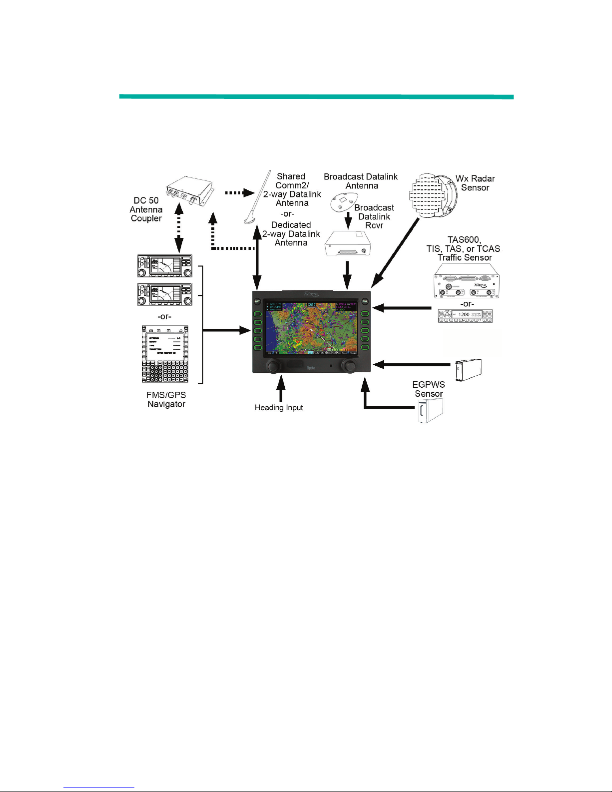
1 Introduction
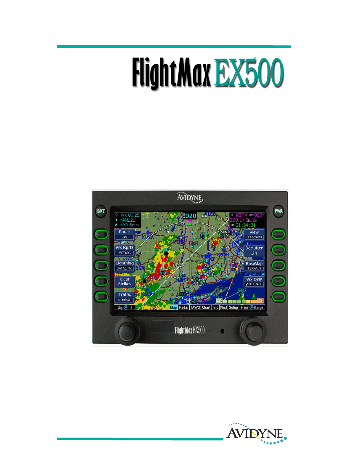
FlightMax EX500 is the most advanced situational awareness system
in general aviation. Its display consolidates information from a variety
of optional sensors in your aircraft (see Figure 1.1).
Figure 1.1 FlightMax EX500 System
Display information includes the following:
● Up to two GPS systems.
● An on-board weather radar.
● Lightning information from a lightning sensor.
● Traffic information from a supported traffic system.
● Terminal procedure chart using the CMax™ function.
● Weather and flight restriction information when interfaced with an
external Broadcast Datalink receiver or internal 2-Way Datalink
receiver.
● TAWS terrain information when interfaced with an installed
EGPWS system.
TWX670/WX-500
Lightning Sensor
Introduction
FlightMax EX500 -2- 600-00078-000 Rev 09
The Flight Manual Supplement (FMS) that is provided with the aircraft
contains information that is specific to your installation and might
contain operating limitations that are applicable to your aircraft
configuration. Please review it before operation.
Note: The FAA requires that Class III aircraft with radar installations
have another independent weather indicator installed as well.
1.1 Starting the EX500
To turn on your EX500 display, do the following:
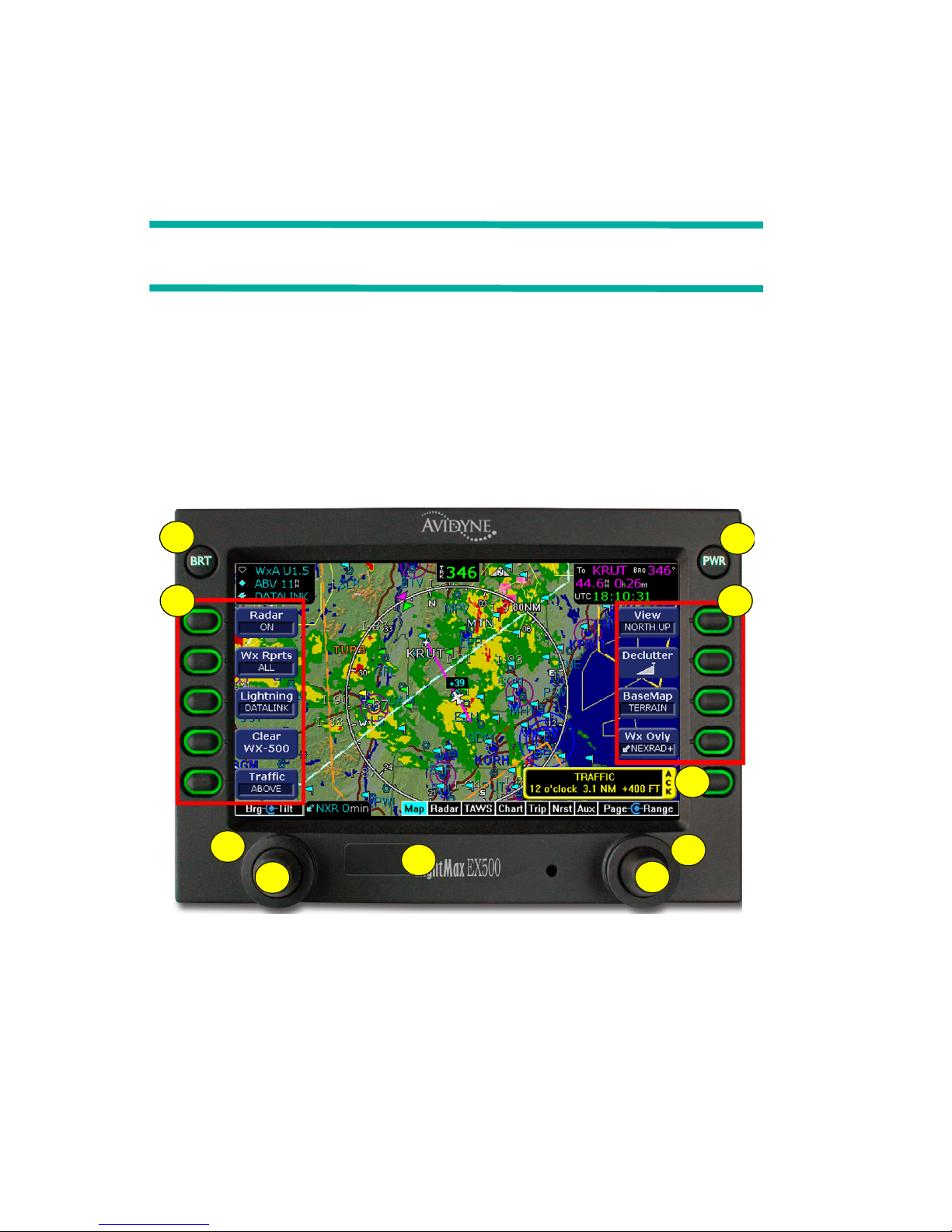
1) Press the PWR button. After a brief initialization period, the
system will display the message, Press Any Bezel Key. The
EX500 displays the Map Page in a configuration that is consistent
with the sensor set that you have installed (see Figure 1.2).
Figure 1.2 Radar-Capable EX500
1) BRT Button - Allows you to set the brightness level of the
EX500.
2) PWR Button - Turns the power on and off. When you turn the
power off, you need to hold the PWR button for a few seconds.
The screen displays the power-down cycle.
8
3 4
6
7
9
10
5
1
2

Starting the EX500
600-00078-000 Rev 09 -3- FlightMax EX500
3) Sensor Buttons - Selects modes or changes the display as
indicated. A button is active when the label appears on the
screen adjacent to the button.
4) Map Function Buttons - Controls the basic look of the map in
terms of orientation, declutter settings, base map features, and
weather overlay.
5) Message Bar - The message bar keeps you informed about
critical as well as routine information from the EX500. When
information needs to be conveyed, the message bar appears
next to the bottom right button.
Note: The message bar displays one message at a time. If more
than one message is available, it will display the highest
priority message first. Press the ACK button to clear the
current message and view those underneath.
6) Radar Bearing Control Knob (Brg) - Controls the radar bearing
selection. If you have radar-capable EX500, see Chapter 4,
Radar Page (Optional), beginning on page 25, for more
information.
7) Radar Tilt Control Knob - Controls the radar’s Tilt selection. If
you have radar-capable EX500, see Chapter 4, Radar Page
(Optional), beginning on page 25,” for more information.
8) Data Port - Provides a front panel access point for loading
database updates. For information on database updates, see
Chapter 12 "Updating Your Databases.
Note: When removing the rubber plug from the data port, pull
the cap gently from the right until it pops out. Make sure
the plug is all the way out before you plug anything into
the USB port.
Do not pull too hard on the tab that attaches the plug to
the EX500. This can separate the plug from the EX500
bezel.

Introduction
FlightMax EX500 -4- 600-00078-000 Rev 09
9) Range & Cursor Control Knob - Allows you to set the Map
range. When other pages are in view, this knob provides cursor
control.
10) Page Control Knob - Provides access to the EX500’s Map,
Radar, TAWS, Chart, Trip, Nearest and Aux Pages. The active
page is highlighted in the lower edge of screen.

2-Knob and 4-Knob Functionality
600-00078-000 Rev 09 -5- FlightMax EX500
1.2 2-Knob and 4-Knob Functionality
Table 1.1 lists the functions of the knobs for the standard and the
radar-capable EX500. The versions have different configurations to
reflect different functionalities, (see Table 1.1).
The knob controls are:
1) Page Control Knob - Provides access to the EX500 Map, Radar,
TAWS, Chart, Trip, Nearest and Aux Pages. The active page is
highlighted in the lower edge of screen.
2) Range & Cursor Control Knob - Allows you to set the Map
range. When other pages are in view, this knob provides cursor
control.
3) Radar Bearing Control Knob (Brg) - Controls the radar bearing
selection. If you have radar-capable EX500, see Chapter 4,
Radar Page (Optional), beginning on page 25 for more
information.
4) Radar Tilt Control Knob - Controls the radar’s Tilt selection. If
you have radar-capable EX500, see Chapter 4, Radar Page
(Optional), beginning on page 25 for more information.
Table 1.1 2-Knob and 4-Knob Functionality
Page
Control
Range & Cursor
Control
Radar Brg Radar Tilt
2-Knob
Left Right N/A N/A
4-Knob
Right outer Right inner Left outer Left inner

Introduction
FlightMax EX500 -6- 600-00078-000 Rev 09
This page intentionally left blank.
Map Page Controls
600-00078-000 Rev 09 -7- FlightMax EX500
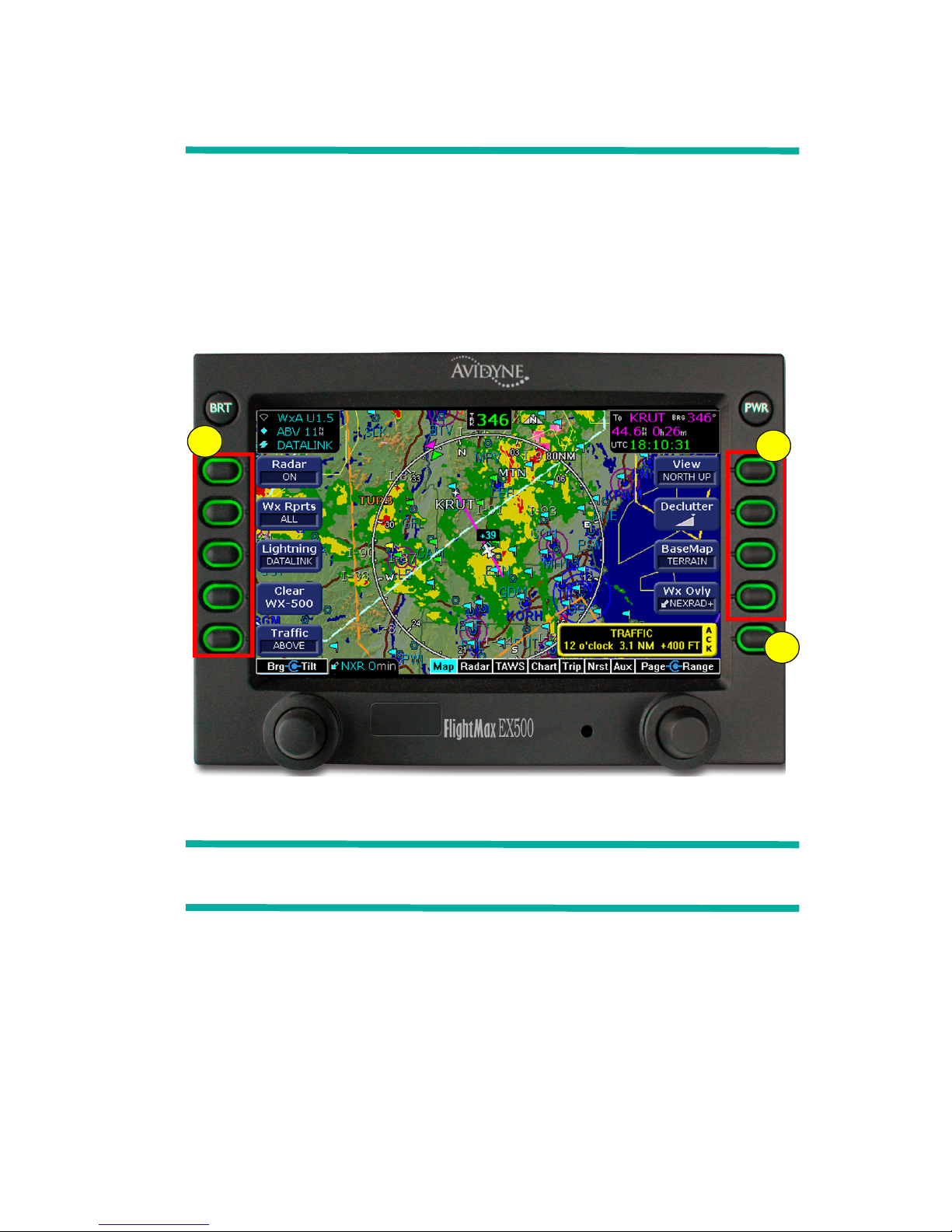
2 Map Page
The Map Page displays your flight plan and position as an overlay of
a map of the current flight area (see Figure 2.1). The EX500 allows
you to select the data you want to display on the Map Page. The
sensor buttons enable you to tailor the information to meet your flying
needs. To display the Map Page, turn the Page knob to Map.
2.1 Map Page Controls
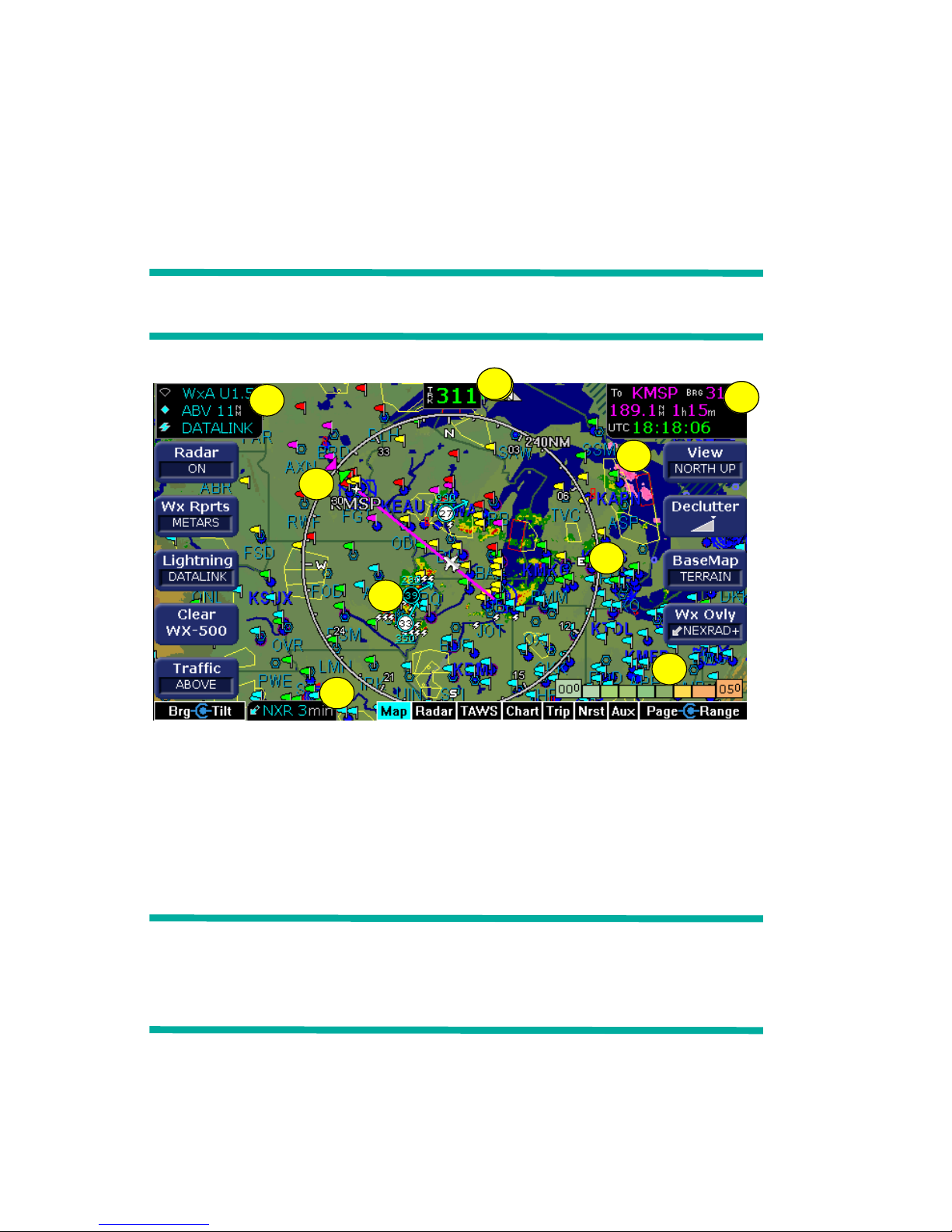
Figure 2.1 EX500 Map Page with Radar
Note: For information about the Map Page symbols, see Map
Symbols on page 118.
1) Sensor Functions - Controls overlay and modes of available
sensors. Buttons are displayed only for the sensors installed in
your aircraft:
■ Radar (if available) - Controls radar function selection.
◆ On - Starts radar operation.
◆ Test - Initiates radar self-test function.
3
1
2

Map Page
FlightMax EX500 -8- 600-00078-000 Rev 09
◆ Standby - Places the radar circuitry in an energized but
inactive state.
Note: When no lightning or traffic sensors are installed, the
lightning and traffic buttons are not displayed on the Map
Page. Instead, dedicated radar function buttons, similar to
those on the Radar Page, are displayed.
For more information about radar functions, see Chapter 4,
Radar Page (Optional), beginning on page 25.
■ Wx Rprts - Controls the type of Datalink weather information
displayed on the map.
◆ All - Displays graphical METARs, AIRMETs, and
SIGMETs.
◆ METARS - Displays graphical METARs only.
◆ AIRMET - Displays graphical AIRMETs only.
◆ SIGMET - Displays graphical SIGMETs only.
◆ DISPLY OFF - Turns off the display of weather
information from the Map Page. While the display is off,
your aircraft may still be receiving weather information.
The Lightning and Traffic buttons are not
displayed for the EX500s that do not have radar,
lightning or traffic sensors installed. Instead, the
METAR and AIR/SIG buttons are displayed.
These buttons are On\Off switches of the
respective features.
Figure 2.2 METAR and AIR/SIG Buttons
Note: For 2-way Datalink, the EX500 does not display graphical
METARs for AWOS reporting stations that are more than
300nm from the current position or for ASOS reporting
stations that are more than 450nm from the current position.
■ Lightning - Controls the display of lightning data on the map
(when interfaced with an Avidyne TWX670, an L3 WX-500
Stormscope, or a satellite-weather Broadcast Datalink
receiver).

Map Page Controls
600-00078-000 Rev 09 -9- FlightMax EX500
◆ Datalink - Displays lightning data obtained from the
Broadcast Datalink system, depending on the level of
your Broadcast Datalink subscription. Lightning symbols
are represented by a lightning bolt symbol in white,
yellow or dark yellow, depending on the age of the strike.
◆ Strike - Displays Strike Mode lightning data obtained
from the lightning sensor. Lightning symbols are
represented by a yellow “X”.
◆ Cell - Displays Cell Mode lightning data obtained from
the WX-500, if installed. Lightning symbols are
represented by a yellow “+.”
◆ Display Off - Turns display of lightning information off.
See Lightning sensor user’s manual for further
descriptions of lightning cells and strikes.
■ Clear Strikes - Removes all onboard-lightning-sensor-
generated lightning strikes from the display. This may enable
you to more clearly see new lightning strikes. Clear strikes
does not remove Datalink lightning.
■ Traffic - Selects the altitude range of the displayed traffic
from the traffic sensor. See your traffic sensor user's manual
for details of available modes.
2) Map Functions - Controls the basic “look and feel” of the map in
terms of orientation, number of elements, and base map.
■ View - Changes the map orientation. Press View to cycle
between the following:
◆ Forward - 120° view with airplane’s present position
displayed at the bottom. Current heading (or track) is
displayed at the top of the map.
◆ Center - 360° view with airplane’s present position
displayed at the center of the compass range ring with
current heading (or track) at the top of map.
◆ North up - 360° view with airplane’s present position
displayed at the center, and north is always at the top of
the map.
■ Declutter - Controls the density of symbols and labels
displayed on the map, from highest to lowest, based on
settings defined on the Declutter Setup Page. See Declutter

Map Page
FlightMax EX500 -10- 600-00078-000 Rev 09
Setup on page 74 for additional information on customizing
the declutter settings.
■ BaseMap - Controls the base map background. Press this
button to cycle through the following display options:
◆ Terrain -Terrain data background with water and geo-
political boundaries.
◆ Base - Black background with water and geo-political
boundaries.
◆ None - Black background. Terrain scale is removed.
■ Wx Ovly - Controls the type of weather information displayed
on the map. Press Wx Ovly to toggle the display options:
◆ - If the 2-Way Datalink is installed and
available, the double-headed arrow displays 2-Way
Datalink NEXRAD information on the map. 2-Way
Datalink uses two-way messaging to send your flight plan
to the Avidyne Network Operations Center (NOC), which
then sends you only the data pertinent to your flight.
◆ - If Broadcast Datalink is installed and
available, the single down arrow displays basic
Broadcast NEXRAD information on the map. Storm cell
movement is not displayed. The external Broadcast
Datalink receiver receives a constant stream of weather
data for the entire United States via a satellite radio
system.
◆ - If Broadcast Datalink is installed and
available (and depending on your level of Broadcast
Datalink service), the single down arrow and plus sign
displays full Broadcast NEXRAD information, including
storm cells.
For many operations, the EX500 displays weather data in
the same way, regardless of which Datalink system is in
use. Both systems provide NEXRAD data—a composite
image depicting precipitation as seen by multiple groundbased weather radar sites. The image is color-coded to
show intensity levels and precipitation types. Broadcast
➡➡➡
Map Page Controls
600-00078-000 Rev 09 -11- FlightMax EX500
Datalink, however, especially at a higher service level,
provides more data (such as storm cell movement and
Datalink lightning).
◆ RADAR - Displays on-board weather radar returns on
the map. This choice does not appear if the EX500 is not
configured with a source of magnetic heading, or if
magnetic heading is currently unavailable.
◆ DSPLY OFF - Removes all radar and NEXRAD data
from the map display.
Note: The boundary of the available NEXRAD data is shown by an
area with gray diagonal stripes. In normal operation, this
boundary follows the outline of CONUS. If, however,
NEXRAD is unavailable in a particular area for any reason,
the hatched lines appear in that area.
3) Map Page Controls are also used to display and acknowledge
system messages.
!
For Broadcast NEXRAD, small areas of high-intensity
NEXRAD data might not be displayed on the EX500 at high
range settings. Instead, larger areas of surrounding lowerintensity returns might occlude indications of severe
precipitation at Map ranges higher than 250 nm. Avoid using
Map ranges greater than 250 nm when NEXRAD echoes are
shown in the vicinity of the aircraft.
!
Do not rely on the EX500 as your sole source for SUAs and
TFRs. Availability of SUA and TFR Status data is subject to
change and source availability. Before conducting flight
operations, always confirm the active state of SUA and TFR
locations with FAA Flight Service.
Map Page
FlightMax EX500 -12- 600-00078-000 Rev 09
2.2 Map Page Symbols—Terrain and Position
The EX500 Map Page uses included and optional sensors to depict
the position of your aircraft in relation to the following: your flight plan,
nearby airports, terrain, traffic, lightning, special use airspace and
other navaids (see Figure 2.3).
Note: For detailed information about each Map Page symbol, see
Map Symbols on page 118.
Figure 2.3 Map Page - Terrain and Position
1) Sensor Status Box - Displays the status of the available sensors
including radar, traffic, lightning and both 2-Way Datalink and
Broadcast Datalink. The NEXRAD (NXR) display includes the
NEXRAD data age, which is the elapsed time since the last
product was created by the weather provider.
Note: NEXRAD is the only Broadcast Datalink product on the
EX500 that displays the time since the product was created
by the weather provider. Refer to the Trip page for
information on all other weather products.
3
3
1
8
6
7
5
9
2
4
Map Page Symbols—Terrain and Position
600-00078-000 Rev 09 -13- FlightMax EX500
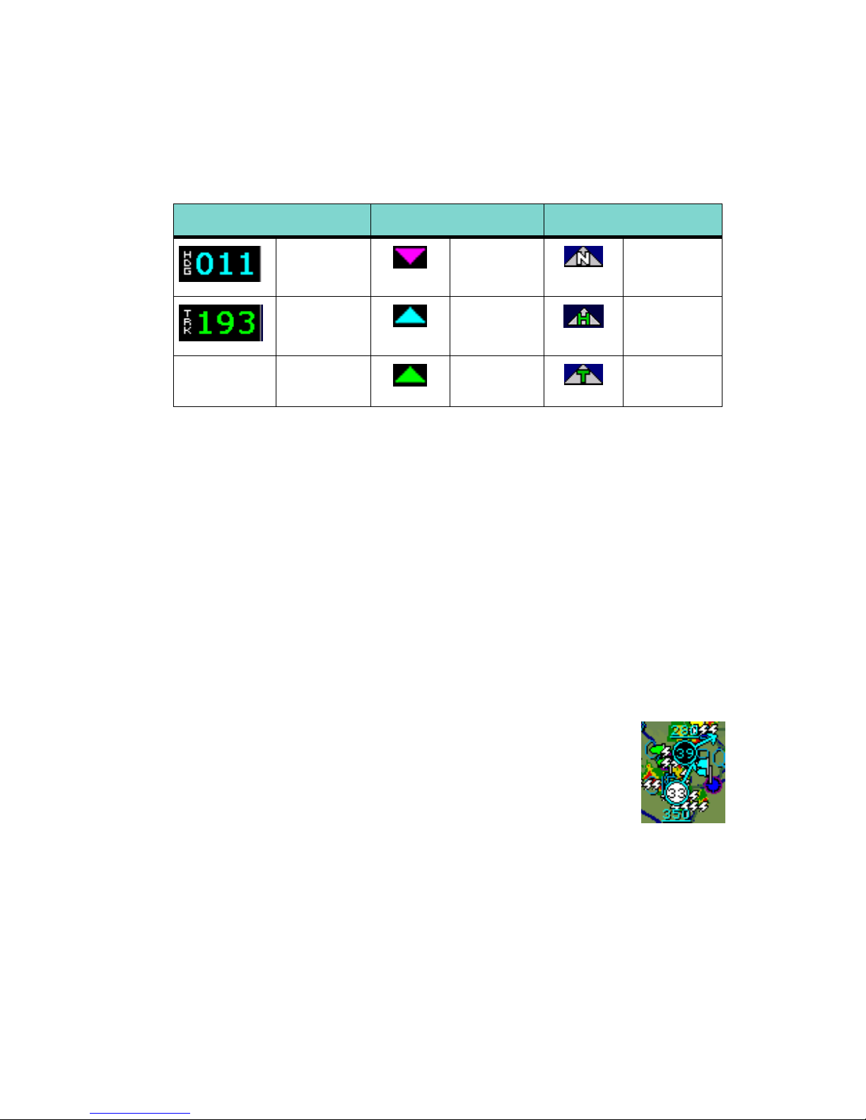
2) Heading/Track Block - The Heading/Track (H/T) Block provides
a digital readout of the current heading, or actual track. Map
orientation is indicated in the triangle to the right of the H/T Block.
3) Data Block - Displays pilot-selected navigation data in the upper
right corner of the screen. See Data Block Setup on page 76 for
details on how to configure this display.
4) Heading/Track Indicator - Three triangles around the compass
range ring provide actual track, desired track, and heading
indications.
5) Lightning and Storm Cell Indications - Displays geographically
referenced lightning strikes (if configured). Strikes are
represented by a yellow “X” in Strike Mode and by a yellow “+” in
Cell Mode (WX-500 only). Strikes from a Broadcast Datalink
system are represented by a lightning bolt symbol in one of three
different colors, depending on the age of the strike.
If you have Broadcast Datalink, and depending on
your level of service, storm cells will show speed and
direction of movement. The underlined number
shows the tops of the storm cell, in hundreds of feet.
The storm cell indicators are black for rain (or snow)
and white to show probability of hail. In the storm cell
example to the right, the bottom storm cell, which includes the
probability of hail, is moving NNE at 33 knots. The cell top is
35,000 feet high.
Table 2.1 Track Indicator Graphics
Heading Track Map Orientation
Heading Desired
Track
North Up
Track Heading Heading Up
Actual
Track
Track Up

Map Page
FlightMax EX500 -14- 600-00078-000 Rev 09
Note: At longer range settings, individual lightning strikes and storm
cells are combined into single strikes or single storm cells,
depending on their proximity. This avoids clutter and
improves readability. And vice versa, lower map range
settings will display more strikes and storm cells.
6) Compass/Range Ring - Displays a 360-degree compass range
ring or a 120-degree compass arc with current range setting. The
range number is the distance from the graphic aircraft symbol to
the outer compass range ring.
7) Special Use Airspace -The EX500 uses several different line
styles to convey special use and class airspaces. Class B, Class
C, Class D, MOA, Warning, and Alert areas, restricted and
prohibited areas are displayed. See Map Symbols—Line Styles
on page 121 for more information.
8) NEXRAD Status Box - If more than three sensors are displayed
in the Sensor Status Box, NEXRAD status is displayed at the
bottom of the page.
9) Terrain Scale - Legend colors represent terrain elevations. The
left number on the scale shows the lowest terrain currently
displayed on the map, and the right number shows the highest
terrain on the map. The terrain scale also displays obstacle
height if the highest obstacle exceeds the highest terrain. A small
cyan window will be displayed when this occurs. Terrain data is
not displayed when that latitude of your aircraft is greater than 75
degrees (north or south).
!
When using Datalink weather, monitor the data age so that
you are aware of the time elapsed since the last weather
update.
 Loading...