

Avidyne Entegra EX5000C Pilot's Manual
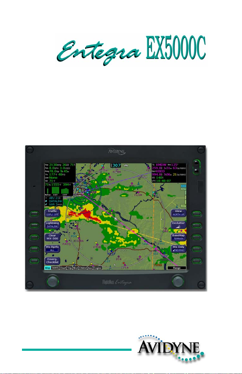
Cirrus SR20 and SR22
Multi-Function Display
Pilot’s Guide
600-00108-000 Rev 07

Document Revision History
Date Revision Description
Mar. 09, 2004 00 Initial Release
Mar. 23, 2004 01 Updated per ECO 04-049
May 28, 2004 02 Updated per ECO 04-100
Sept. 02, 2004 03 Updated per ECO 04-120
Sept. 15, 2005 04 Updated per ECO 05-157
March 1, 2006 05 Updated per ECO 06-040
Sept. 22, 2006 06 Updated per ECO-06-190
Aug. 8, 2007 07 Updated per ECO-07-261
System Configuration
When contacting your dealer or Avidyne technical support, and whe n
logging onto MyAvidyne.com for the first time, please have your
EX5000C serial number available:
Entegra EX5000 S/N: ________________________________
This document is applicable to Software Part Number 530-00195-100.
All materials copyrighted including images that represent this software
Copyright 2007 Avidyne Corporation. All rights reserved.
600-00108-000 Rev 07 -i- Entegra EX5000

About this Guide
This guide assumes that all available sensors and softw ar e op tio ns
have been installed in your airplane. The page layouts and button
descriptions in this guide may differ slightly from what you observe on
your EX5000. If your system is configured with a partial set of the
available sensors, then some views may differ from this guide.
Note: All images contained within this document, including scree nshots and
other displays, are for reference use only and are subject to change. The
images contained herein may differ slightly from your actual equipment or
display.
Entegra EX5000 - ii- 600-00108-000 Rev 07
Notes and Warnings
Notes and warnings provide guidance for the use of the EX5000.
Avidyne strongly suggests that you pay close attention to notes and
warnings for your own safety.
For example:
Note: Notes provide useful information about how to use the EX5000.
Warnings are prefaced with exclamation points and denote
information that can prevent serious injury or death on the
!
The instructions and warnings in this manual are not int en ded to
replace the instructions and warnings for other equipment on your
aircraft. It is critical that you as the pilot in command have a complete
understanding of the warnings, operating instructions, and limitations
for all equipment installed on your aircraft.
!
part of the user.
This manual assumes that the reader is an appropriately
licensed pilot. Avidyne strongly recommends that you use the
EX5000 only under VFR conditions until you are very familiar
with the EX5000.
If you have questions, please contact Avidyne at 800-284-
3963 (800-AVIDYNE) before operating with the EX5000 under
IFR conditions.
Before conducting flight operations, be sure to verify that time
and date settings on the System Time Setup Page are correct
and in GMT (UTC). It is critical that the time be set to GMT to
!
!
600-00108-000 Rev 07 -iii- Entegra EX5000
provide accurate display of Datalink weather. See Section
8.1, "Aux Main Page" on page 61 for more information.
When using the EX5000, be sure to cross-check the data
displayed against other data sources for accuracy including
other flight deck instruments and charts.
!
!
!
!
The displayed terrain and obstacle indicators are only
advisory. Do not rely on the EX5000 as the sole source of
obstacle and terrain avoidance information. Always refer to
current aeronautical charts for appropriate terrain and
obstacle information.
The EX5000 is not intended to replace your navigation charts
or primary navigation aids. Use the EX5000 as a supplement
to other navigation sources, to enhance your overall
situational awareness. Do not rely on the navigation data in
your EX5000 as your sole reference for navigation.
While a properly updated database contains the latest official
information available, the manufacturers will not be held
responsible for any inaccuracy or omissions therein. Never
use the terrain displayed on the EX5000 as the only reference
for terrain avoidance.
The transmission of datalink weather information means there
is some delay from real time until the weather information is
displayed on the EX5000. Therefore, use datalink weather
information only for strategic route planning. Avoid severe
weather areas with a safe margin of distance. Do not use the
EX5000 to penetrate severe weather, thunderstorms, cells or
lines of cells.
By using Broadcast datalink, you can access weather
information made available from sources external to Avidyne
Corporation. Avidyne does not control, edit or review the
content of such information and is not responsible for such
information or the actions or conduct of any company that
provides sources of weather data through the Broadcast
datalink. Therefore, ALL WEATHER DATA ARE PROVIDED
!
Entegra EX5000 -iv- 600-00108-000 Rev 07
AS-IS and neither Avidyne nor its suppliers, subcontractors,
or developers (collectively called “Suppliers”) are responsible
for: 1) the accuracy, completeness, timeliness, reliability,
content, or availability of the weather data or any other
datalink information accessed; 2) loss or damage to your
records or data; or 3) your use of, or results achieved from,
the weather data or any other information accessed.

!
Notice regarding NOTAM information
NOTAM information is subject to constant change and it is
extremely important that all pilots check with Flight Service for
applicable NOTAMs prior to EVERY flight. Call 1-800WXBRIEF (992-7433) for the latest information.
The NOTAM information provided by the EX5000 is for
planning purposes only. Always consult official NOTAMS for
the latest restrictions.
Avidyne does not provide a complete list of NOTAMS. Local
NOTAMS, most laser light NOTAMS, and any NOTAMS other
than restricted airspace are not listed.
By using the Avidyne Services you are able to access
information made available from a variety of sources. Avidyne
does not control, edit or review the content of such info rmation
and is not responsible for such information or the actions or
conduct of any company that provides sources of weather
data procured by Avidyne. Therefore, although Avidyne uses
diligent efforts to provide Services of high quality, ALL
SERVICES AND WEATHER DATA ARE PROVIDED AS-IS
and neither Avidyne nor its suppliers (including ORBCOMM
and its affiliates), subcontractors, information sources or
developers (collectively called “Suppliers”) are responsible for:
1) the accuracy, completeness, timeliness, reliability, content,
or availability of the Services or any information accessed; 2)
loss or damage to your records or data; or 3) your use of, or
results achieved from, the Services or any information
accessed.
600-00108-000 Rev 07 -v- Entegra EX5000

Copyrights and Trademarks
Charts shown in the CMax™ section of this manual are copyright
Jeppesen Sanderson, Inc.
All trademarks and trade names are the property of their respective
owners.
Note: The navigation data for the EX5000 includes copyrighted data
compilations owned by Jeppesen Sanderson, Inc., for which Avidyne has
been granted a limited, non-exclusive license to use. The copyrighted
subject matter may be used only in connection with the ordinary and
intended use of the EX5000 as described in this manual. Use for any other
purpose, or reproduction or copying of any portion of said copyrighted
subject matter, is strictly prohibited.
All materials copyrighted including images that represent this software.
Copyright 2005 Avidyne Corporation. All rights reserved.
Entegra EX5000 -vi- 600-00108-000 Rev 07

AVIDYNE EXCLUSIVE LIMITED WARRANTY/LIMITATIONS
ON LIABILITY
Avidyne warrants the Product manufactured by it against defects in material and workmanship
for a period of twenty-four (24) months from delivery. If Avidyne's Product fails to conform to
this warranty, Avidyne, in its sole discretion, will either repair or replace the Product or provide
a refund of the purchase price paid for the Product. This warranty is made upon the express
conditions that:
(a) Avidyne is given prompt written notice of any claimed non-conformity in the Product, with a
reasonable explanation thereof;
(b) The Product is returned to Avidyne or to an Avidyne authorized service facility;
(c) The Product has not been altered in any manner other than as previously authorized by
Avidyne in writing; and
(d) Repairs to the Product have not been made by anyone other than Avidyne or an Avidyne
authorized service facility.
This warranty does not apply to any Product which is not installed, maintained and operated in
accordance with Avidyne's written instructions or which is otherwise misused, including,
without limitation, to any Product which is damaged due to improper installation, maintenance
or operation, tampering, alteration of serial numbers or other manufacturers data, lightning or
other electrical source, or otherwise.
If warranty protection is applicable to the Product, Avidyne will use reasonable efforts to repair
or replace Product within ten (10) business days of its receipt of the Product.
Any Product that has been repaired by Avidyne or replaced by Avidyne under this warranty will
be subject to remainder of the original warranty term applicable to the repaired or replaced
Product or will be warranted under the warranty terms above for ninety days from the date of
repair or replacement, whichever period is longer.
This exclusive limited warranty applies in lieu of and expressly supersedes and excludes all other
representations, affirmations and/or warranties, whether express or implied, oral or written,
including, without limitation, any warranty of merchantability, of fitness for a particular purpose, of
title and/or of non-infringement. purchaser expressly and knowingly agrees that no other
representations, affirmations or warranties, whether express or implied, oral or written, form part of
any purchase and sale transaction related to the product.
Avidyne's (and its affiliates') and any product component supplier's sole responsibility and liability
related to the product or arising out of or related to its purchase, sale, performance, reliability or use
are limited to its repair or replacement, or to a refund of the purchase price, in Avidyne's sole
discretion. in no event will Avidyne (or its affiliates) or any suppliers of product components be
responsible or liable for any other damage of any nature whatsoever, including direct, indirect,
incidental, consequential, special, loss of use, loss of revenue or profit, property damage, personal
injury, wrongful death, or other damage (whethe r or not Avidyne (or its affil iates) were notified of the
possibility that any damage might be incurred), arising out of or related to the product, its purchase
or sale, its performance or reliability, or the use or inability to use the product, for any reason,
including due to any PRODUCT DEFECT OR DEFECTS OR A NY ACTION OR INACTION OF ANY
nature (including claimed or actual negligen ce or gross negligence) by Avidyne or any suppliers of
600-00108-000 Rev 07 -vii- Entegra EX5000

product components. neither this exclusive limited warranty nor Avidyne's or any product
component supplier's responsibility or liability will in any way be enlarged or otherwise altered due to
Avidyne's provision of technical support or training relate d to th e pr od u ct.
Without limiting the foregoing, neither Avidyne (nor its affiliates) make any representations,
affirmations or warranties regarding or rela ted to products not manufactured by Avidyne or
regarding or related to the performance or reliability of any such product, either alone or when used
with any product manufactured by Avidyne, or the suitability of any such product for use with any
product manufactured by Avidyne. Avidyne (and its affiliates) expressly disclaim any and all
representations, affirmations and/or warranties regarding or related to any such product s. in no
event will Avidyne (or its affiliates) be responsible or liable for any damage of any nature
whatsoever, including direct, indirect, incident al, conseq uential, spe cial, loss of use, lo ss of revenue
or profit, property damage, personal injury, wrongful death, or other damage (whether or not
Avidyne (or its affiliates) were notified of the possibility that any damage might be incurred), arising
out of or related to products not manufactured by Avidyne, the purchase or sale of such products,
their performance or reliability, either alone or when used with any product manufactured by
Avidyne, or the suitability of any such product for use with any product manufactured by Avidyne.
This exclusive limited warranty also applies in lieu of and expressly supersedes and excludes all
other rights any purchaser has or may have related to the product and/or arising out of or related t o
its purchase, sale, performance, reliability o r use, eithe r alone or wi th any ot her produc t or products,
whether in contract, in tort (including rights sounding in negligence, strict liability and
misrepresentation), under statute, at law, in equity, or otherwise, and purchaser expressly and
knowingly waives all such rights to the fullest extent permitted by law. purcha ser also exp ressly and
knowingly agrees that the product is not a consumer good.
The foregoing four paragraphs define and limit Avidyne's sole responsibility and liability and
purchaser's sole and exclusive remedies related to the prod uct. Some jurisdictions may not allow
the exclusion or limitation of warranties or liabil i ties, in which case the above limitations or
exclusions, or some of them, may not apply in those jurisdictions.
Entegra EX5000 -viii- 600-00108-000 Rev 07

600-00108-000 Rev 07 -ix- Entegra EX5000

Contents
1 Introduction ..............................................................1
Using the Entegra EX5000 MFD..................................................2
Power Up .....................................................................................4
2 Map Page...................................................................6
Map Page—Controls....................................................................7
Map Page Symbols—Terrain and Position................................11
Map Page Symbols—Runways and Flight Plan ........................15
Map Orientation Control.............................................................17
Errors Displayed on the Map Page............................................17
Loss of GPS Input ...............................................................17
Loss of Heading Input..........................................................18
3 Traffic Mode and the Traffic Page.........................19
The Dedicated Traffic Page .......................................................19
Traffic Symbols ..........................................................................22
TIS Sensor Status......................................................................23
4 TAWS Page (Optional)...........................................24
TAWS Information......................................................................24
TAWS Operation........................................................................27
TAWS Reference.......................................................................29
Auto-Range .........................................................................29
Simultaneous Alerts.............................................................29
Terrain Messages and Error Indications..............................29
5 Trip Page.................................................................31
Trip Page Information ................................................................31
6 Nearest Page (NRST) .............................................37
Nearest Page.............................................................................37
Airport Info Page.................................................. ... ... ... ... ..........39
7 Checklists ...............................................................40
Checklist Versions ..................... ... ... ... .......................................40
Normal Checklists......................................................................41
Checklist Buttons and Knobs.....................................................43
Emergency Checklists ..................... ... .... ... ... ... .... ......................44
Performance Checklists................................... .... ... ... ... ... .... ... ...47
8 CMax Chart Pages (Optional)................................48
About CMax ...............................................................................48
About Geo-Referenced Charts ..................................................49
CMax Chart Page ......................................................................49
Entegra EX5000 -x- 600-00108-000 Rev 07

CMax Views...............................................................................53
Procedure Chart Views....................................... .... ... ... ... ... 53
Airport Chart Views.......................................... ...................55
CMax Selection Page................................................................57
Selecting an Airport.............................................................59
Chart NOTAMs Page..........................................................61
9 Engine Page ........................................................... 63
Cirrus Engine Page ................................................................... 64
Initial Usable Fuel Page.............................................................70
Using Lean Assist......................................................................71
Leaning for Best Power.......................................................71
Leaning for Best Economy..................................................72
Data Blocks on Map Page.........................................................74
Lean Data Block States.................... ... ................................74
EMax Total Engine Management ..............................................75
10 Aux Pages – Configuring the EX5000.................. 76
Aux Main Page..........................................................................76
Airport Filter Setup Page........................... .... ............................78
Declutter Setup Page ............................................. ... .... ... .........80
Data Block Edit Page.................................................................82
System Time Page....................................................................84
11 Using Datalink (Optional)...................................... 86
About Datalink Weather.............................................................86
Map Page with Datalink Weather.............................................. 88
Symbols Displayed using Datalink......................................89
Using Datalink without a Traffic Sensor..............................91
Trip Page with Datalink Weather............................................ ... 92
Nearest Page with Datalink Weather.........................................94
Datalink Coverage.....................................................................95
12 Using the EX5000 Outside the US........................ 97
Features Available in the US Only.............................................97
Features Specific to International Flight ....................................97
13 Reference................................................................ 99
Updating Your Databases .......................................................100
Loading NavData (the Navigation Database)....................101
Loading CMax Chart Data.................................................103
Downloading EMax Data...................................................104
Broadcast Datalink Service Purchase and Activation..............106
Setting Up a Broadcast Datalink Account......................... 106
Using WSI Broadcast Weather on the Sirius Satellite Network.....
600-00108-000 Rev 07 -xi- Entegra EX5000

106
Setting up a WSI Broadcast Datalink Account ..................107
Activating WSI WX Satellite Weather................................107
Using Sirius Audio....................................................................108
Setting up a Sirius Audio Account .....................................108
Activating Sirius Audio ......................................................109
Activating XM WX Satellite Weather .................................109
ICleaning the EX5000 Screen.......... ... .... ... ... ... .... ... ... ... ... .... ... .111
Sensor Status Block Symbols..................................................112
Map Symbols ...........................................................................114
Line Styles ..............................................................................116
Data Blocks ...........................................................................117
TAWS Messages .....................................................................119
Nav Messages .........................................................................121
Traffic Messages......................................................................123
Lightning Messages.................................................................125
Engine Messages ...................... ... ... ... .....................................128
PFD Messages..................................................................131
Broadcast Datalink Messages ................................................132
Abbreviations and Definitions ..................................................136
14 Software License. .................................................138
Entegra EX5000 -xii- 600-00108-000 Rev 07

List of Figures
Figure 1.1 Entegra EX5000 MFD........................ ... ............................ 2
Figure 1.2 EX5000 Startup Page........................................................4
Figure 2.1 Map Page Controls............................................................7
Figure 2.2 Map Page Symbols–Terrain and Position. ... ...... ... .... ... ...11
Figure 2.3 Map Page Symbols—Runways and Flight Plan..............15
Figure 3.1 Map Page—Traffic Mode ................................................20
Figure 4.1 TAWS Information...........................................................24
Figure 4.2 Terrain Caution Condition ...............................................27
Figure 4.3 Terrain Warning Condition ..............................................28
Figure 5.1 Trip Page Information......................................................31
Figure 6.1 Nearest Page ..................................................................37
Figure 6.2 Airport Information Page .................................................39
Figure 7.1 Normal Procedure Checklist............................................41
Figure 7.2 Normal Checklists ...........................................................42
Figure 7.3 Example Normal Checklist..............................................43
Figure 7.4 Emergency Checklists.....................................................44
Figure 8.1 CMax Chart Page (Airport)..............................................50
Figure 8.2 CMax Chart Page (Procedure)........................................52
Figure 8.3 Procedure Chart views....................................................54
Figure 8.4 Airport Chart Views .........................................................55
Figure 8.5 Airport Departure Chart (Night View) ..............................56
Figure 8.6 CMax Selection Page......................................................57
Figure 8.7 Airport Selection Page.....................................................59
Figure 8.8 Chart NOTAMs Page ......................................................61
Figure 9.1 Engine Main Page...........................................................64
Figure 9.2 Initial Usable Fuel Page ..................................................70
Figure 9.3 Leaning for Best Power...................................................72
Figure 9.4 Leaning for Best Economy..............................................73
Figure 9.5 Engine Data Blocks—Map Page.. ... ... ... .... ... ...................74
Figure 10.1 Aux Main Page..............................................................76
Figure 10.2 Airport Filter Setup Page...............................................78
Figure 10.3 Declutter Setup Page ...................................................80
Figure 10.4 Data Block Edit Page ................................................. ...82
Figure 10.5 System Time Page........................................................84
Figure 11.1 Datalink Weather—Map Page.......................................88
Figure 11.2 Datalink Weather without Traffic Sensors.....................91
Figure 11.3 Trip Page with Datalink Weather................... ... ... .... ... ...92
Figure 11.4 Nearest Page with Datalink Weather ............................94
Figure 11.5 Example of Area Covered by Broadcast.......................95
Figure 11.6 Limits of Datalink Coverage Area..................... ... .... ... ...96
600-00108-000 Rev 07 -xiii- Entegra EX5000

List of Tables
Table 2.1 Track Indicator Graphics ................................................12
Table 2.2 Obstacle Graphics..........................................................17
Table 3.1 Traffic Symbols...............................................................22
Table 4.1 EGPWS Display Color Formats......................................30
Table 8.1 Airport Procedure Views.................................................54
Table 8.2 Airport Chart Views.........................................................55
Table 13.1 Sensor Status Block Symbols ....................................112
Table 13.2 Broadcast Datalink Sensor Status Block (Optional)...113
Table 13.3 Map Symbols – Airports .............................................114
Table 13.4 Map Symbols – Navigational Fixes ............................115
Table 13.5 Map Symbols – Traffic Symbols.................................115
Table 13.6 Map Symbols – Other.................................................115
Table 13.7 Airspace and Airways Lines .......................................116
Table 13.8 AIRMET and SIGMET Boundary Lines..................... .116
Table 13.9 Data Block Information ...............................................117
Table 13.10 Engine Instrument Data Block Information...............118
Table 13.11 TAWS Messages......................................................119
Table 13.12 Nav Messages..........................................................121
Table 13.13 Traffic Messages......................................................123
Table 13.14 Lightning Messages..................................................125
Table 13.15 Engine Messages.....................................................128
Table 13.16 PFD Messages.........................................................131
Table 13.17 Broadcast Datalink Messages..................................132
Table 13.18 Avionics Abbreviations and Definitions.....................136
Entegra EX5000 -xiv- 600-00108-000 Rev 07

This page intentionally blank
600-00108-000 Rev 07 -xv- Entegra EX5000

1 Introduction
The Entegra EX5000 Multi-Function Display (MFD) provides a
moving map view of your flight plan, broadcast datalink weather,
lightning, traffic, navigation data, obstacles, terrain, and CMax™
approach plates with an intuitive user interface. The EX5000 offers
the following standard and optional features:
● Engine instruments display.
● Normal and Emergency Checklist display.
● Lightning information display from a WX-500 or Avidyne TWX-
670 lightning sensor, if installed.
● Full ARINC-429 databus capability, allowing the EX5000 to
display of curved flight paths, procedure turns, and holding
patterns from a compatible GPS navigator.
● Traffic information display from Avidyne TAS600 Series, L-3
Skywatch, or Garmin TIS traffic systems.
● Terminal procedure chart display using the CMax™ function.
● Display of weather and flight restriction information when
interfaced with an external Broadcast Datalink receiver.
● Display of TAWS terrain information when interfaced with an
installed EGPWS system.
Note: Consult the Flight Manual Supplement (FMS) provided with
the aircraft and/or sensors prior to operation. The FMS contains
information specific to your installation and may contain operating
limitations applicable to your aircraft configuration.
Entegra EX5000 -1- 600-00108-000 Rev 07
Using the Entegra EX5000 MFD
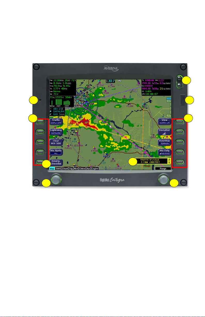
1.1 Using the Entegra EX5000 MFD
The controls on the bezel of the Entegra EX5000 are placed to allow
you quick and intuitive access to the information yo u need , when you
need it (see Figure 1.1).
2
1
4
5
7 8
6
Figure 1.1 Entegra EX5000 MFD
1) PhotoCell Light Sensor—Automatically compensates display
brightness for varying lighting conditions.
2) Brightness Control—Allows you to override the default display
brightness and adjust the brightness level. Press the top of the
button to brighten the display; press the bottom to dim it.
3
4
600-00108-000 Rev 07 -2- Entegra EX5000

Introduction
3) Data Port—Provides a front panel access point for loading
database updates.
Note: When removing the rubber cap from the data port, pull the cap
gently from the top until it pops out. Make sure the cap is out of the
way (but not removed) before plugging anything into the USB port.
Do not tug on the tab at the bottom of the cap; this can cause the
loss of the protective cap.
4) Buttons—Used to select modes or change the display as
indicated. Buttons are active when a label appears on the screen
adjacent to the key.
5) Emerg. Checklist—The Emerg. Checklist button is always
available to provide quick access to the Emergency Checklists.
For more information, see Section 7.4, "Emergency Checklists"
on page 44.
6) Message Bar—The message bar keeps you informed about
critical as well as routine information from the EX5000. When
information needs to be conveyed the message bar appears next
to the bottom right button.
Note: The message bar displays one message at a time. If more
than one message is available, the message bar will display the
highest priority message first. Press the ACK button to clear the
current message and view those underneath.
7) Page Control Knob—The left knob provides quick access to the
main EX5000 pages, including the Map Page, Trip Page, and
Aux Page, as well as the main pages for any optional features.
The current page is highlighted in the Page Bar on the lower left
corner of the screen.
8) Selection & Range Control Knob—Depending on the page you
are viewing, the right knob controls functions such as selecting
items on the page or changing the view range. The label on right
knob changes as appropriate.
Entegra EX5000 -3- 600-00108-000 Rev 07

Power Up
1.2 Power Up
On power up, the system performs a brief hardware self-test, then
systematically initializes its functions. After the system initializes
(about a minute after power-on), the title page, with database
currency information, is displayed.
When the EX5000 is ready the message, “Press any bezel key to
continue”, is displayed.
Figure 1.2 EX5000 Startup Page
The EX5000 Startup Page reports the valid dates for the currently
loaded CMax
™
and NavData. Check to ensure that you do not have
any expired databases before continuing.
For CMax data:
● If the issue date for the next update has passed, the Startup Page
displays “Update Available” in white.
● If the current date is more tha n a wee k pa st the issu e of the next
update, “Update Required” displays in yellow cautionary text.
● If CMax is more than 10 weeks out of date, access to the charts is
revoked until new CMax data is loaded.
600-00108-000 Rev 07 -4- Entegra EX5000

Introduction
For NavData, the date range displays if the data is valid; if it is not
valid, the word “EXPIRED” and the expiration data display in yellow.
For more information about updating CMax and NavData, see
Section 13.1, "Updating Your Databases" on page 100.
Note: When you press a bezel key from the Startup Page, either the
Initial Fuel Page or a series of three Cirrus-defined Safety Pages
™
display (For aircraft with EMax
, the Initial Fuel Page displays first) .
Read these pages carefully to determine your readiness for flight.
Depending on your aircraft’s features, either the Map or Engine Page
displays after you read and respond to the Safety Pages.
Entegra EX5000 -5- 600-00108-000 Rev 07

2 Map Page
The Map Page displays your current flight plan overlaying a map of
the area over which you are flying. The EX5000 allows you to select
the data you want to display on the Map Page.
Turn the Select knob on the Page Bar to Map to display the Map
Page.
This section discusses the following topics:
● Map Page—Controls, page 7
● Map Page Symbols—Terrain and Position, page 11
● Map Page Symbols—Runways and Flight Plan, page 15
● Map Orientation Control, page 17
● Errors Displayed on the Ma p Page , page 17
Note: On startup, you may see three Cirrus-defined Safety Pages
after the Startup Page. Read these pages carefully to determine your
readiness for flight. The Map Page displays after you read and
respond to the Safety pages.
Entegra EX5000 -6- 600-00108-000 Rev 07
Map Page
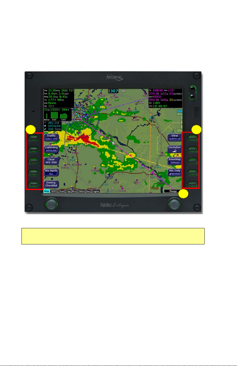
2.1 Map Page—Controls
Buttons on the left side of the bezel provide access to sensor modes
and pages. Buttons on the right side of the bezel access the mapping
functions, and control how the Map is viewed.
1
3
Figure 2.1 Map Page Controls
Note: For information about the Map Symbols, see Section
13.7, "Map Symbols" on page 114.
1) Sensor Functions—Control overlay and modes of available
sensors. Buttons only display for the sensors installed in yo ur
aircraft:
■ Traffic—Cycles through traffic sensor modes. See
Chapter 3 "Traffic Mode and the Traffic Page ,” for more
information on traffic modes.
2
■ Lightning—Depending on your broadcast service level,
when both Broadcast Datalink and an onboard lightning
sensor are installed, cycles through lightning sensor modes
and overlays in the following order; Strike, Cell (WX-500),
Entegra EX5000 -7- 600-00108-000 Rev 07

Map Page—Controls
Datalink, Display Off. When only one source of lightning data
is installed, only the appropriate modes are available. See
your lightning sensor User’s Manual for further details.
Note: (For WX-500 only.) The lightning sensor maps thunderstorm activity
by monitoring electrical discharge activity within a 200-mile radius of the
aircraft. If the display range is set to less than 25NM, only lightning strikes
within 25NM are shown. If the display range is set to greater than 25NM, all
lightning strikes are shown.
■ Clear Strikes—Removes current lightning symbols to allow
for the refresh of lightning data when using a onboard
lightning sensor. Does not remove Datalink lightning.
■ WX Rprts—Controls the type of Datalink weather information
displayed on the map, as follows:
◆ All—Displays graphical METARs, AIRMETs, and
SIGMETs.
◆ METARS—Displays graphical METARs only.
◆ AIRMET—Displays graphical AIRMETs only.
◆ SIGMET—Displays graphical SIGMETs only.
◆ DSPLY OFF—Turns off display of all weather
information.
For more information about Datalink functions, see Section
11.2, "Map Page with Datalink Weather" on page 88.
■ Emerg. Checklist—Opens the Emergency Checklist Page.
For more information, see Section 7.4, "Emergency
Checklists" on page 44.
2) Map Functions—Controls basic look of the map in terms of
orientation, number of elements, and base map.
■ View—Orients the map for either Track/Heading Up or North
Up. FORWARD and CENTER views are oriented with Track/
Heading Up. North Up orients the map to true North, with the
ownship symbol rotated to show track/heading.
■ Declutter—Controls the four levels of navigation database
detail on the Map from most to least:
➡➡➡
600-00108-000 Rev 07 -8- Entegra EX5000

Map Page
■ Base Map—Controls the base map layers:
◆ TERRAIN—Color-contoured terrain, bodies of water, and
political boundaries.
◆ BASE—Bodies of water and Political boundaries
◆ NONE—No base map
■ WX Ovly—Displays only when Broadcast Datalink is
installed. Controls the type of weather information displayed
on the map. Press WX Ovly to toggle the display between:
◆ —If Narrowcast Datalink is installed, displays
Narrowcast NEXRAD information on the map.
Narrowcast uses two-way messaging to send your flight
plan to the Avidyne Network Operations Center (NOC),
which then sends you only the data pertinent to your
flight.
◆ —Displays Broadcast NEXRAD information
on the map. Storm cell are not displayed.
◆ —The (+) plus option shows broadcast
NEXRAD overlay with storm cell icons. This option may
not be available depending on your broadcast
subscription level.
◆ NONE - Removes all NEXRAD data from the map
display.
3) Range Control Knob—The right knob controls the map’s range
and allows you to set the scale from 1NM out to 1500NM. The
selectable ranges are, in nautical miles, 1, 2, 5, 10, 15, 20, 30,
40, 50, 75, 100, 150, 200, 300, 400, 500, 750, 1000, and 1500.
Note: The terrain base map is automatically removed and Nav
database information is fully decluttered at 750NM and higher
ranges.
Entegra EX5000 -9- 600-00108-000 Rev 07

Map Page—Controls
Note: The Map Page monitors the “health” of the sensors (traffic and
lightning) by means of a signal pulse. Map looks for a signal every
three seconds from each sensor. If it doesn’t see this signal it
assumes the sensor has failed in some way. When this happens, the
following occurs on the display:
• Sensor data is removed from the overlay display.
• The word “FAIL” displays in the sensor's status line in yellow.
• The sensor symbol changes from cyan to yellow (if the sensor was on).
What to do:
Select the Setup Page and perform Self-Test for the applicable
sensor.
600-00108-000 Rev 07 -10- Entegra EX5000
Map Page
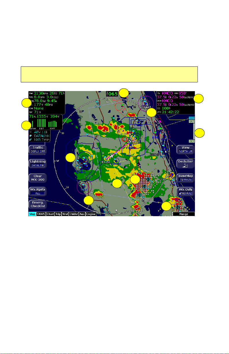
2.2 Map Page Symbols—Terrain and Position
The EX5000 Map Page depicts your aircraft’s position in relation to
your flight plan, nearby airports, terrain, traffic, lightning, special use
airspace and other navaids.
Note: For details about the Map Symbols, see Section 13.7, "Map
Symbols" on page 114.
2
1
4
3
6
8
7
9
10
Figure 2.2 Map Page Symbols–Terrain and Position
1) Data Blocks (Left & Right)—View navigation and engine (when
equipped with engine monitor) data in data blocks in the upper
corners of the display. For more information, see Section
10.4, "Data Block Edit Page" on page 82.
1
5
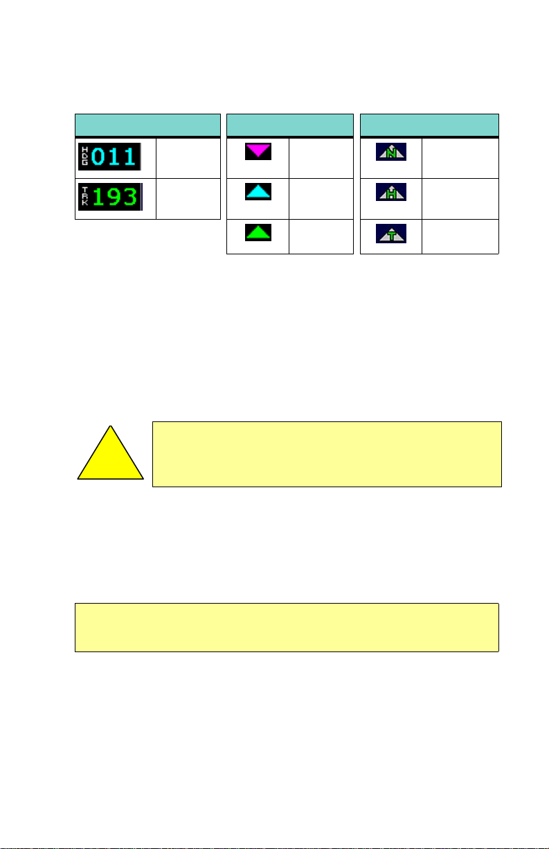
2) Heading/Track Indicator—Three triangles around the comp ass
rose provide actual track, desired track, and heading indications.
The H/T Block provides digital readout of the current heading, or
actual track. Map orientation is indicated in the triangle to the
right of the H/T Block.
Entegra EX5000 -11- 600-00108-000 Rev 07
Map Page Symbols—Terrain and Position
Table 2.1 Track Indicator Graphics
Heading Track Map Orientation
Heading Desired
Track
Track Heading Heading Up
North Up
Actual
Track
3) Sensor Status Box—Displays the status of the available
sensors including radar, traffic, lightning and both 2-Way Datalink
and Broadcast Datalink. The NEXRAD (NXR) display includes
the NEXRAD data age, which is the elapsed time since the
product was created by the weather provider.
13.1 Sensor Status Block Symbols on page 112 for more
information on status box symbols. (Optional Engine Instrument
Sensor Status information is described in Table 13.10 Engine
Instrument Data Block Information on page 118).
When using Datalink weather, monitor the data age so
you are aware of the time elapsed since the last
!
4) Compass Rose/Range Ring—Displays a 360-degree or 120-
degree compass circle or arc and indicates current rang e setting.
The range number is the distance from the airplane symbol to the
compass arc.
Note: NEXRAD is the only Broadcast Datalink product on the EX5000 that
displays the time since the product was created by the weather provider.
Refer to the Trip page for information on all other weather products.
weather update.
See Table
Track Up
600-00108-000 Rev 07 -12- Entegra EX5000
Map Page
5) Terrain Scale—Shows highest and lowest limits of terrain in
displayed area. Legend colors in between these numerics
represent terrain elevations. Blue obstacle clearance number
shows the top of the highest obstacle, when greater than the
highest displayed terrain. Terrain data is not di splayed when your
aircraft’s latitude is greater than 75 degrees (north or south).
The displayed terrain and obstacle indicators are only
advisory. It is dangerous to rely on the EX5000 as the
sole source of obstacle and terrain avoidance
!
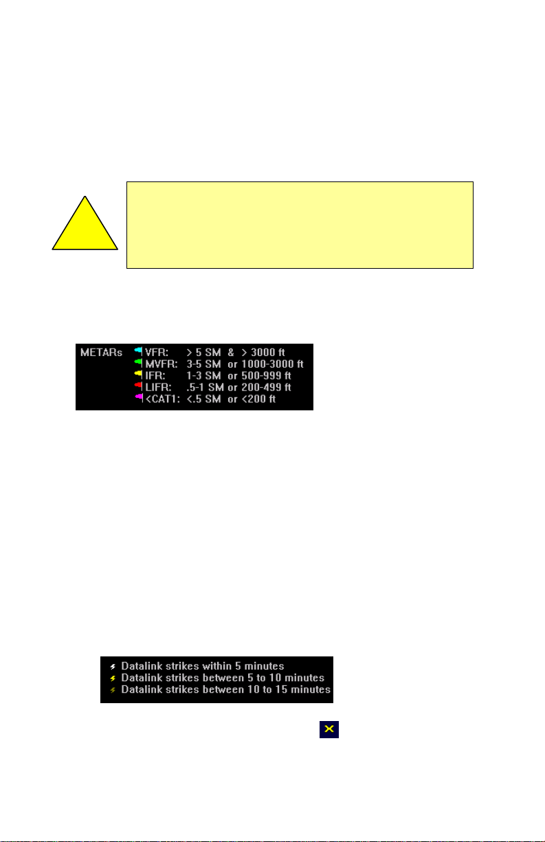
6) METAR Flags—For each reporting airport, when Datalink is
installed and active, a METAR flag provides a quick overview of
the weather for that station. The METAR flags are color-coded:
7) Interstate Highways—Depicted as brown lines when terrain is
selected to be shown. Interstates are labeled in white. (e.g. I-95).
Highways are removed from the terrain map when the range is
greater than 300NM.
information. Always refer to current aeronautical charts
for appropriate terrain and obstacle information.
8) Lightning Indications—If configured with WX-500 or TWX-670
sensor, shows geographically referenced lightning strikes.
Lightning strikes from onboard sensors display for three minutes.
Lightning display depends on the selected mode, as follows:
■ Datalink Mode—If Broadcast Datalink is installed and you
have an appropriate broadcast datalink service level, shows
as color-coded lightning symbols. Datalink strikes darken in
color until they are removed after 15 minutes.
■ WX-500 or TWX-670 Strike Mode—
Entegra EX5000 -13- 600-00108-000 Rev 07

Map Page Symbols—Terrain and Position
■ WX-500 Cell Mode—
9) Special Use Airspace—The EX5000 uses several different line
styles to convey special use and class airspaces. Class B is solid
blue line, Class C is solid magenta line. Class D is dashed blue
line, MOA, Warning, and Alert areas are solid yellow lines, and
restricted and prohibited areas are solid red lines. See Table
13.7 Airspace and Airways Lines on page 116.
10) Storm Cells—If storm cells are present, the EX5000 displays the
cells along with the cell’s groundspeed, in knots, and direction of
travel, and it shows the cell echo tops with a label. If there is a
greater than 50% chance of hail, the cell displays with a white
background.
600-00108-000 Rev 07 -14- Entegra EX5000
 Loading...