

Avidyne Entegra Pilot's Manual


Revision History
Rev Number Date of Release Reason for Release
00 April 2009 Initial Release of document
that coincided with Software
Release 9.0.0
01 June 2009 Release of document that
coincided with Software
Release 9.0.1
02 September 2009 Release of document that
coincided with Software
Release 9.0.2
03 June 2010 Release of document that
coincided with Software
Release 9.1.0
04 February 2011 Release of document that
coincided with Software
Release 9.2.0
05 June 2014 Release of document that
coincided with Software
Release 9.3.0
06 October 2017 Release of document that
coincided with Software
Release 9.4
Which adds ADS-B Receiver
support and LP+V capabilities

Entegra Flight Display System | Release 9 PILOT GUIDE
TABLE OF CONTENTS
1
System Overview ..............................................................1-2
FUNCTIONAL OVERVIEW ..........................................................1-2
BASIC CONCEPTS ......................................................................1-3
REDUNDANCY ............................................................................1-9
MODULAR DESIGN ...................................................................1-10
DATABUS ...................................................................................1-10
HARDWARE MODULARITY ......................................................1-10
SOFTWARE MODULARITY .......................................................1-12
DISPLAY ENHANCEMENTS .....................................................1-12
AIRCRAFT CONFIGURATION MODULE ..................................1-13
HOW TO USE THE REST OF THIS MANUAL ...........................1-13
2 Normal Startup Sequence ................................................2-2
SYSTEM POWER ........................................................................2-2
BRIGHTNESS CONTROLS .........................................................2-2
STARTUP INDICATIONS .............................................................2-2
3 Ground Operations ...........................................................3-2
ELECTRONIC CHECKLIST .........................................................3-2
ENTERING A FLIGHT PLAN ........................................................3-3
USE OF THE ENGINE TAB .........................................................3-8
SETTING UP THE RADIOS AND TRANSPONDER ....................3-9
SETTING UP THE AUTOPILOT .................................................3-12
TAXI CHARTS ............................................................................3-14
ALTIMETER SETTING ...............................................................3-15
4 Departure ...........................................................................4-2
DEPARTURE PROCEDURES .....................................................4-2
VSPEEDS ON ASI ........................................................................4-5
ENGINE INDICATION ON ADI .....................................................4-5
5 Cruise / Enroute ................................................................5-2
NAVIGATIONAL SITUATIONAL AWARENESS ...........................5-2
PRECISION FLYING ....................................................................5-3
ENGINE LEANING .......................................................................5-5
USE OF THE MAP .......................................................................5-6
FMS OPERATIONS ......................................................................5-9
USE OF NEAREST FUNCTION .................................................5-18
DATALINK WEATHER OPERATIONS .......................................5-19
ON-BOARD WEATHER RADAR ................................................5-28
AUTOPILOT OPERATIONS .......................................................5-31

USE OF VECTORS MODE ........................................................5-31
SYNTHETIC VISION ..................................................................5-32
TERRAIN AWARENESS (SV-TA) ..............................................5-36
6 Arrivals/Approaches/Landing ..........................................6-2
ENROUTE DESCENTS ................................................................6-2
ENTERING AN ARRIVAL AND APPROACH ...............................6-4
USE OF THE SPLIT PAGES ........................................................6-7
USE OF APPROACH CHARTS....................................................6-9
FLYING AN AUTOPILOT COUPLED APPROACH ......................6-9
USE OF THE TIMER ..................................................................6-15
TAXI CHARTS ............................................................................6-16
7 Diverts/Missed Approach es .............................................7-2
MISSED APPROACH ...................................................................7-2
RETRY APPROACH ....................................................................7-3
8 Night Operations ...............................................................8-2
IFD DISPLAY BRIGHTNESS .......................................................8-2
IFD BEZEL BRIGHTNESS ...........................................................8-2
KEYBOARD DISPLAY BRIGHTNESS .........................................8-2
KEYBOARD BEZEL BRIGHTNESS .............................................8-2
CHARTS LIGHTING SCHEME .....................................................8-2
DISPLAY OF TERRAIN ON MAP .................................................8-3
9 System Alerts ....................................................................9-2
CAS SYSTEM...............................................................................9-2
MISCOMPARES ...........................................................................9-6
CROSSCHECK MONITOR ..........................................................9-8
10 System Failures.............................................................. 10-3
POWER DISTRIBUTION ............................................................10-3
LOSS OF IFD 2-IFD CONFIGURATIONS ..................................10-3
LOSS OF IFD 3-IFD CONFIGURATIONS ..................................10-5
LOSS OF DISPLAY ....................................................................10-5
LOSS OF KEYBOARD ...............................................................10-6
LOSS OF AHRS, AIR DATA OR ADAHRS (DUAL) ....................10-7
LOSS OF AHRS, AIR DATA OR ADAHRS (SINGLE) ................10-8
WARMSTART.............................................................................10-9
FAST ERECT ...........................................................................10-10
LOSS OF ENGINE DATA .........................................................10-10
KEYBOARD CONTRAST NEEDS ADJUSTING.......................10-11
LOSS OF LOWER HALF OF AN IFD .......................................10-11
11 System Setup / User Preferences................................. 11-2

MAIN 11-2
DISPLAY ....................................................................................11-3
FMS 11-4
MAP 11-5
DATABLOCKS............................................................................11-5
AUTOPILOT ...............................................................................11-6
12 System Updates ............................................................. 12-2
DATA UPDATES ........................................................................12-2
DATALOGS DOWNLOAD ..........................................................12-5
SOFTWARE UPDATES .............................................................12-7
13 Release 7/8 to Release 9 Differen c es ........................... 13-2
Appendix A – PFD ...................................................................... 1
SETTING UP THE S-TEC 55X AUTOPILOT ................................. 16
Appendix B – FMS Pages .......................................................... 1
Appendix C – Map Pages ........................................................... 1
Appendix E – Checklist Pages .................................................. 1
Index ............................................................................................ 1

System Overview
1-1
1 System Overview ..............................................................1-2
FUNCTIONAL OVERVIEW ..........................................................1-2
BASIC CONCEPTS ......................................................................1-3
Page Function Keys .............................................................................. 1-3
Line Select Keys ................................................................................... 1-4
Display Formats .................................................................................... 1-5
ADI Upper Half ...................................................................................... 1-6
Primary Navigation Source ................................................................... 1-6
Full Alpha-numeric keyboard with display ............................................. 1-6
Live Edits…........................................................................................... 1-7
Overlays…… ........................................................................................ 1-8
Panning……. ........................................................................................ 1-8
Integration with other systems ............................................................... 1-8
Caution-Warning System ...................................................................... 1-9
Datablocks…. ....................................................................................... 1-9
REDUNDANCY ............................................................................1-9
MODULAR DESIGN ...................................................................1-10
DATABUS….. .............................................................................1-10
HARDWARE MODULARITY ......................................................1-10
SOFTWARE MODULARITY .......................................................1-12
DISPLAY ENHANCEMENTS .....................................................1-12
Cleaning the Display ........................................................................... 1-12
AIRCRAFT CONFIGURATION MODULE ..................................1-13
HOW TO USE THE REST OF THIS MANUAL ...........................1-13

1-2 System Overview
1 System Overview
FUNCTIONAL OVERVIEW
The Avidyne Entegra Release 9 flight display system supports the
following functions:
• Primary Flight Display
• Flight Management System
• SBAS GPS Navigation
• VHF Radio Nav/Com
• Attitude and Air Data Sensors
• Moving Map
• Weather Inform ation vi a Datalink or ADS-B Receiver
• Traffic
• Lightning
• Electronic Approach Pla tes
• Engine Display (not available on all aircraft)
• Electronic Checklist
• Data Logging
• Caution-Warning System
• Enhanced Vision (optional)
• Synthetic Vis i on

System Overview 1-3
• Weather Radar (not available on all aircraft)
The system has been designed for single-pilot IFR operation and
features a Page and Tab user interface.
Functions revolve around the five Page Function Keys that
appear across the bottom edge of the bezel. Each of the five
functional pages has associated tabs, which contain related data,
often in different views. These functions and tabs are covered in
detail throughout this reference manual. The primary method for
accomplishing a task will be outlined, and if applicable, alternative
methods will be explained in the appendices. One consistent
message that will be emphas i zed is the method and position of
displaying data does not change between these different views
and tabs. Avidyne strongly believes in the concept “Fly like you
train and train like you fly”. In other words, the same views used
on a daily basis are identical to what is available during
emergency and reversionary conditions.
The reversionary capability is inherent to the redundancy of the
Integrated Flight Displays (IFD) and the dual-databus
architecture. The system architecture allows selection of five
separate display functions on any display. This eliminates the
need for special reversionary display modes with reduced
functionality, and reduces complexity and training requirements
for the pilots.
BASIC CONCEPTS
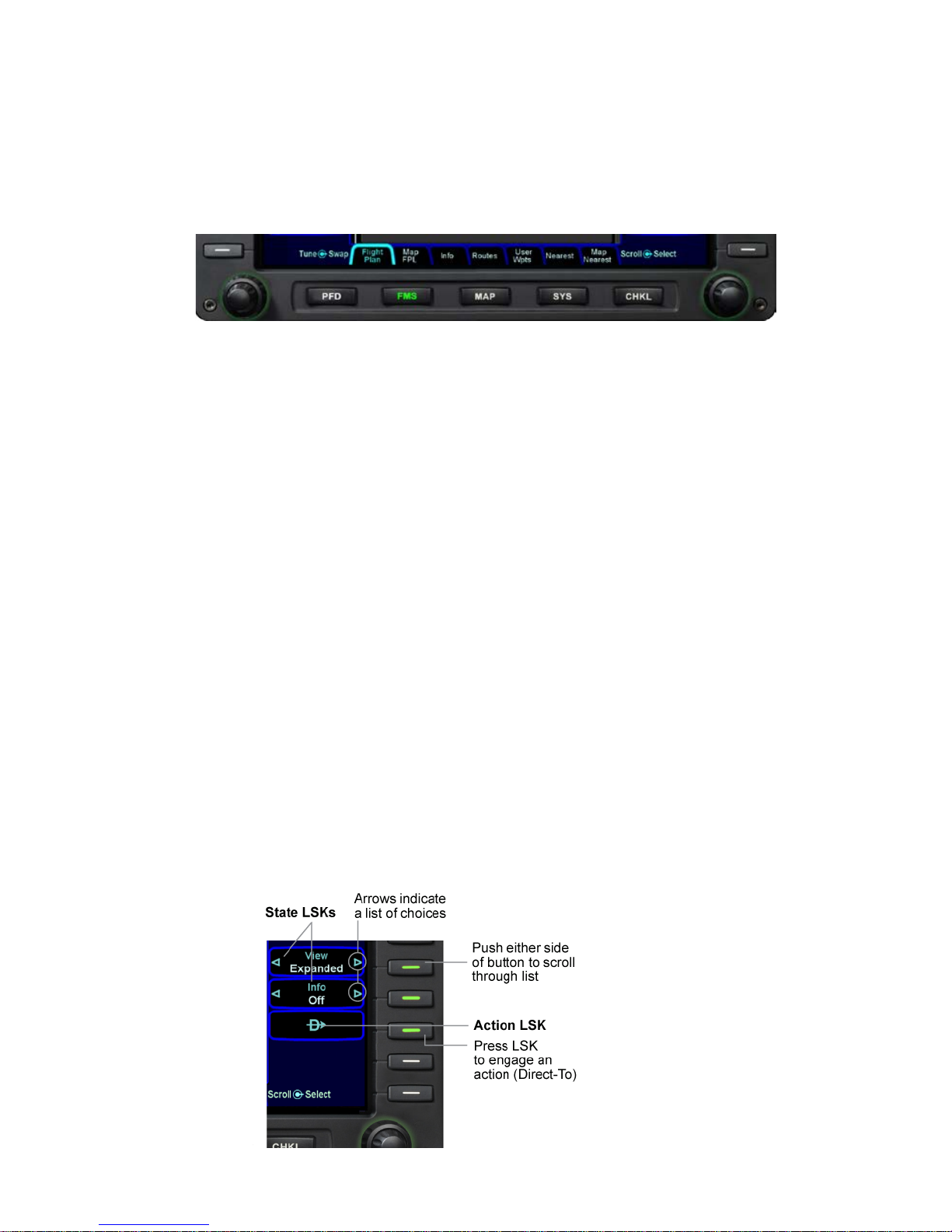
PAGE FUNCTION KEYS
The 5 buttons along the bottom of the IFD bezel are called Page
Function Keys. Each key is labeled by function:
• PFD (Primary Flight Display)
• FMS (Flight Management System)
• Map (Moving Map)
• SYS (System Pages)
• CHKL (Electronic Checklist)
Each page has a number of associated tabs. Each Page
Function key has a left and right rocker nature to it. Select the
page of interest by pressing the middle of the Page Function Key
1-4 System Overview
and navigate through the ava ila ble ta bs by pressing the left or
right side of the Page Function Key. Continue pressing one side
of the function key to automatically step through the tabs.
Page Function Keys and Tabs
LINE SELECT KEYS
Line Select Keys, typically abbreviated to LSK in this m anual,
are the buttons found along the left and right sides of the bezel. A
label, just inside the bezel – adjacent to the physical LSK,
indicates the function of the LSK. Each LSK is capable of being
individually backlit to help the pilot identify the correct LSK.
Pressing the LSK either performs the labeled action or changes
the state, which is indicated by the left and right arrows. These
LSKs function by rocking left or right on the key. For the cases
where there is a list of selectable options, browse the list in either
direction by pressing the left or right side of the LSK. This
becomes a time saving technique when trying to rapidly navigate
a large list and minimizes time recovering from list overshoots by
providing the ability to back up one select ion.
LSK Types
• State LSKs – Right and left arrows indicate a list of
choices. Traverse the list by rocking left or right on the
line select key.
• Action LSKs – Pressing the LSK enables the action
indicated on the label.

System Overview 1-5
COOL FEATURE
Addressable Line Select Keys On any given page
only LSKs that can perform the labeled function are
backlit. Keys that are non-functional are intentionally
unlit. This is to visually “quiet” the display, reduce
time searching for a desired button and also
minimize extra pilot actions caused by inadvertently
pressing the wrong button. This feature is especially
useful at night in a darkened cockpit.
DISPLAY FORMATS
• Half format – The PFD attitude indicator (ADI), airspeed,
altimeter and vertical speed indicators are always on the
top half of the page. The bottom half of the page is
dependent on which Page Function Key and tab are
selected. Whenever the bottom half of the page is not a
traditional HSI, the lower edge of the ADI has a
perspective compass and Horizontal Deviation Indicator
(HDI).
• Full format – The function selected (e.g. Map or Chart)
takes up the entire screen. Associated line select keys
can be pilot-selected to time out in preset durat ions or
never.
• Datablock format – The left and right sides of the IFD
are populated with various pil ot-selectable datablocks.
• Split format – The IFD is split vertically, down the center,
allowing two distinct functions to be displayed at the
same time. Examples include Map-Chart and Map-FLP.
The ND box concept refers to the rectangular section on the
lower half of the PFD pages. It is most noticeable on the PFD
where the upper half is always a PFD view. The ND box is filled
based on which Page Function Key is pressed along the bottom
edge of the IFD bezel,
All pages are available at all times with only one key press.

1-6 System Overview
ADI UPPER HALF
The system has been configured to recognize in which position
each display is located in the cockpit. This means that the PFD
will always display an ADI on the upper half of the display,
regardless of which page function keys are pressed along the
bottom of the bezel.
PRIMARY NAVIGATION SOURCE
The means of selecting which nav source is driving the deviation
indicators on the PFD and HSI as well as the source driving the
autopilot when the autopilot is in NAV mode comes from the
Primary Nav LSK on the PFD. Choices are FMS, Nav1, Nav2.
The FMS will automate the Primary Nav LSK mode change from
FMS to Nav 1 and automatically toggle the autopilot from HDG to
NAV APPR on int erc ept ing a locali zer and chan ge the Primary
Nav LSK when going missed after an approac h.
FULL ALPHA-NUMERIC KEYBOARD WITH DISPLAY
The system comes equipped with an alpha-numeric keyboard to
assist control of navigation and communication. It has two rows of
dedicated function keys along the top edge that are grouped
together in logical functions to include:
• Com Radio Selection
• Nav Radio Selection
• Auxiliary Radio Functions
• Transponder Mode Selection
• FMS Shortcuts (Direct-To, Nearest, Procedures)
• Map panning and control
The keyboard is the primary location to conduct all Com Tuning. It
is also the primary location for autopilot target setting using the
dedicated knob controls along the bottom edge. Nav tuning is
automatic in this system in that the FMS automatically tunes all
navaids that are part of the active flight plan. As a means of
backup, manual nav tuning can be conducted from the keyboard.

System Overview 1-7
The keypad is a QWERTY layout with a few special function
buttons along the outer edges and a row of number keys along
the top of the keypad.
Just above the keypad is a display that is split into two distinct
areas: a semi-permanent display of the com and nav frequencies
on the left half of the display and a set of user-configurable
datablocks in the right half. This datablock area is temporarily
replaced by a display that is relevant to the operation being
performed on the keyboard (e.g. com tuning, transponder code
input, autopilot target setting, FMS data entry, etc).
Keyboard
LIVE EDITS
All edits are “live edits” in that they are immediately applied.
Examples include:
• Course Entry on PFD
• Com tuning on keyboard (new frequency becomes the
active radio standby freq)
• Nav tuning on keyboard (new frequency becomes the
active radio standby freq)
• Waypoint name entries in flight plans
• Autopilot targets (Altitude, Heading, Vertical Speed)
• Waypoint deletions in flight plans

1-8 System Overview
OVERLAYS
The system supports overlays of data controlled via the LSKs.
Examples on the Map pages include being able to turn on or off:
• Datalink NOWrad weather displays
• Datalink Icing displays
• FIS-B Weather displays
• AIRMETS/SIGMETS
• METAR flags
• Flight Plan (on PFD HSI)
• CDI (on PFD HSI)
PANNING
The map pages support a panning capability. Using a joystick on
the keyboard, any map page on the MFD provides the ability to
pan anywhere on the map, zoom in or out as desired, hover over
hotspots and see information boxes pop-up.
INTEGRATION WITH OTHER SYSTEMS
Integration is provided with other systems such as traffic
awareness system (TAS), ADS-B receiver, transponder, audio
select panels and autopilot.
Traffic sensor data is permanently displayed on all map pages,
the ND box and in a dedicated traffic thumbnail display. Traffic
sensor modes and display ranges can be controlled through
various LSK options.
The level of transponder integr ati on dep ends on which
transponder the airplane is equipped with. If equipped with a
remote-mounted Mode C, Mode S or Mode ES transp onder , al l
transponder mode and code changes are commanded through
the keyboard and this data is displayed prominently on the
displays. If equipped with a panel mount transponder, most of the
transponder mode and code control, as well as display, remain on
the panel mount transponder.
The level of audio select panel integration depends on which
audio panel the airplane is equipped with. If equipped with an

System Overview 1-9
Avidyne-compatible PS Engineering PMA8000B Audio Select
Panel, the PFD displa ys the frequency and station identifier of the
active com frequency just below the VSI in the primary field of
view.
The integration with the DF C100 aut opi lot is a tighter int egrat io n
than previous display-autopilot integrations. New features such
as VNAV and Envelope Protection have been added as well as
tight integration with the FMS400/900w. This eliminates the need
for manually pressing the autopilot control head buttons and
reduces pilot workload in many flight scenarios.
CAUTION-WARNING SYSTEM
A caution warning system is provided in this system, comprised of
a set of Master Caution “Warning” and “Caution” lamps in the
primary field of view of the PFD; a system of Warning (red),
Caution (amber), and Advisory (cyan) alert messages that are
displayed to the pilot, and a dedicated page for display of all
active alerts.
DATABLOCKS
As noted earlier in this section, many pages are presented in a
datablock format on the MFD and keyboard. Data such as
waypoint and nav data, com/nav frequencies, transponder codes,
UTC or Local time, and engine parameters are all selectable for
display in these datablock fields. The keyboard display is also
configured to allow display of pilot-selectable datablock fields.
REDUNDANCY
Since all IFDs are identical pieces of hardware, running identical
software, they are 100% interchangeable. These IFDs and
keyboards are all interconnected via a dual, digital Databus. This
means all sensor data is available to all IFDs, all the time.
External sensors (e.g. traffic, lightning, datalink, etc.) are
connected to the basic system via one or more of the I/O “blades”
and all IFDs have access to that information. The more sensors
that talk directly on the digital Databus, the less the wiring
required to support it, which translates directly to less weight and

1-10 System Overview
less complexity.
MODULAR DESIGN
This system was designed to be modular; modular in the overall
architecture, hardware, software and from a packaging
perspective. This approach produces future extensibility and
provides Avidyne with flexibility in adapting the system to meet
future needs.
DATABUS
One of the key modularity components employed in this system is
the databus. This dual, digital databus is peer-to-peer, meaning it
is not reliant on a single designated bus controller passing data
serially to every component on board. Instead, every component
individually passes data to the bus during a given time slot and
selects only the data it is interested in seeing from other
components.
For additional information on databuses and how the y are
relevant to the behind-the-scenes operation of the system, see
this article “What’s Next in Avionics” accessible via this hyperlink:
http://www.avidyne.com/news/index.asp
A true dual-redundant peer-to-peer databus improves critical
sensor availability, and computation modules are not “daisychained” together in a manner that can create cascading failures.
With a true dual redundant databus, single-point failures remain
just that, single point failures. They do not adversely affect other
vital, otherwise operati ona l f unc tiona lity.
A true dual redundant databus design means true reliability and
redundancy. Unlike other systems that require complex, limited,
and unfamiliar reversionary modes this offers double critical
function redundancy via the dual redundant databus architecture.
HARDWARE MODULARITY
There are spare modular avionics slot in each IFD available for
future functions. When new requirements emerge or hardware
technology advances, a new module can be added or an existing

System Overview 1-11
module may be replaced with an updated one. This enables an
easy upgrade path for existing aircraft in the field. The hardware
modules have considerable unused processing, memory and
communication bandwidth allowing for maximum functional
expansion without changing the existing hardware. In many
cases, software upgrades may be accomplished without
removing units from the aircraft.
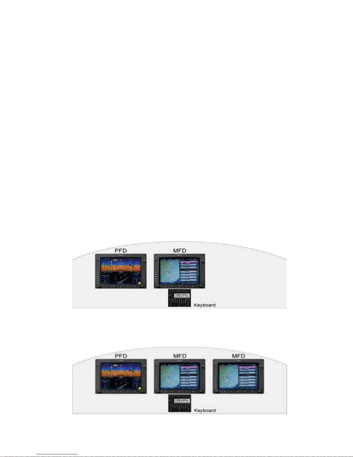
The image below shows the back of an IFD and a close up view
of the LRU blades that slide in.
The basic system consists of a FMS900w control panel, or
“keyboard” (not shown), and two Integrated Flight Displays
(“IFDs”) that are self-contained units with an internal card cage for
LRUs; that means they are built with a number of slots designed
to fit individual component LRUs. These LRUs can slide in and
out of the IFD and include the ADAHRS, the SBAS GPS, the
digital VHF radios, and the I/O interface.
LRU modules as part of an integral chassis
Other variations of the system include single ADAHRS LRUs (vs.
dual ADAHRS) and FMS400 instead of FMS900w.

1-12 System Overview
In the single ADAHRS configuration, the ADAHRS is physically
housed in the left IFD and the right IFD has an empty slot for the
missing LRU. The attitude and air data from the single ADAHRS
is still capable of being displayed on all IFDs.
The FMS400 is still a full-featured FMS but does not support
precision SBAS approaches (LPV), airways nor drop down
options for arrivals and departures. There is no capability to have
a combination of FMS900w and FMS400 systems in the same
airplane.
SOFTWARE MODULARITY
The software architecture is specifically designed to be
partitioned and promote the advantages of higher levels of
integration without compromising safety by generating the
unwanted side effects of failure propagation.
DISPLAY ENHANCEM ENTS
These new displays are a second-generation display system with
enhanced characteristics over first generation displays systems
and include:
• 768 x 1024 display resolution
• LED backlight technolo g y
• 1000 nit brightness
CLEANING THE DISPLAY
If the IFD screen should become dirty due to fingerprints or dust,
clean the screen using the following materials and methods:
• A clean, soft lint-free cloth such as 3M Ultra-Brite Cloth
#2011 or similar
• A cleaning solution composed of de-ionized water. Do not
use any alcohol-based product. Always apply the
cleaning solution directly on the cloth. Never spray
cleaner directly on the screen.
System Overview 1-13
The use of any 3rd party screen protect or, es pec ial l y thos e that
adhere directly to the IFD display glass, is not endorsed by
Avidyne and may void the warranty for any display related issue.
AIRCRAFT CONFIGURATION MODULE
An Aircraft Configuration Module (ACM) stores all aircraft-specific
avionics configuration information.
The ACM plugs directly into the back of an Integrated Flight
Display and remains with the aircraft harness. This means if an
entire IFD needs to be removed for service, or a replacement is
re-installed, calibrations, aircraft configuration, and pilot
preferences are automatically loaded into the replaced unit. This
saves significant maintenance time and reduces the likelihood of
data loss.
HOW TO USE THE R EST OF THIS M ANUAL
2 IFD configuration reference
3 IFD configuration reference

1-14 System Overview
When describing a function or behavior for a specific IFD, the
term PFD and MFD will frequently be used. In this context, the
left-most IFD will be referred to as the “PFD” and the middle and
right-hand IFDs will each be referred to as the “MFD”.
Starting with Section 2, the manual is organized in a phase-offlight order. Alerts, Failures and Set up ch apters foll o w, ultimately
ending with a number of appendices, which are organized by
Page Function Keys.
When viewing the electronic version of this ref er ence manual,
there are several hyperlinks embedded in the text that provide
easy links to more detailed material. Double clicking the hyperlink
(indicated by underlined text) will automatically launch your
computer browser to the appropriate location.
This manual assumes that the pilot is appropriately licensed, is
proficient in operation of the aircraft and its equipment, and is in
compliance with all Federal Aviation Regulations (FARS).
Areas of special significance, from a safety perspective, are
identified in cautionary Notes within the manual. Pilots should
give close attention to these notes.
All images contained in this manual are for reference use only,
and are subject to change.
Avidyne strongly recommends that pilots use the Entegra
Integrated Flight Display Release 9 System only under VFR
conditions until completely familiar with its operation and use.

Normal Startup Sequence 2-1
2 Normal Startup Sequence ................................................2-2
SYSTEM POWER ........................................................................2-2
BRIGHTNESS CONTROLS .........................................................2-2
STARTUP INDICATIONS .............................................................2-2

2-2 Normal Startup Sequence
2 Normal Startup Seque nce
SYSTEM POWER
The IFDs and keyboard will automatically start when the aircraft
bus power is applied.
After power application, the keyboard display will be visible as
well as the Brt/Dim rocker key on the IFDs. Several seconds later,
the IFD displays will begin to have indications.
There are no On or Off controls for the equipment, each IFD is
regulated by a pair of circuit breakers. Both units would need to
be disconnected in order to remove power and is not something
expected to be performed for normal operations. The keyboard is
regulated by a single circuit breaker and fed by the essential bus.
BRIGHT NESS CO NTROL S
Each IFD has its own brightness control on the bezel to control
the individual displa y bright nes s . Power-on brightness of both the
IFD displays and the keyboard display will be 100% – there will
be no need to increase display brightness. Bezel background
lighting is controlled via the cockpit dimming controls/rheostats.
STARTUP INDICATIONS
During normal start up conditions, there are no special startup
screens or displays that appear. The PFD will present an Attitude
Heading Reference System (AHRS) alignment box in the upper
half of the display and the MFD will present the Initial Fuel view of
the Engine tab.
AHRS alignment time is approximately 2 minutes and 45 seconds
from the time the AHRS alignment box is displayed on the PFD.
Normal Startup Sequence 2-3
The alignment state is updated during that process to provide
information on alignment status and indications of completeness.
While early taxi is permitted prior to alignment for flexibility,
Avidyne highly recommends that the aircraft remain stationary
until the alignment of all AHRS are complete and the alignment
boxes are replaced by the ADI.
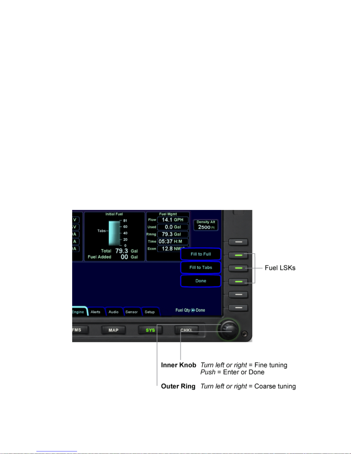
Until an initial fuel state has been entered, all other bezel controls
for the MFD are locked out. In other words, until an initial fuel
value has been entered via one of the labeled line select keys
along the right side of the bezel or via the right hand knob, no
other pages or tabs can be accessed on the display.
Note: It is critical that you accurately enter the amount of usable
fuel on board, so as to ensure the accuracy of the fuel totalizer
and fuel range ring functions. The image below describes the fuel
entry options.
Fuel entry options

2-4 Normal Startup Sequence
In dual Air Data and Attitude Reference System (ADAHRS)
equipped systems, each IFD ADAHRS aligns independently.
Therefore, it is recommended that each ADAHRS is verified to
have aligned prior to taxi or takeoff by either checking the PFD
tab of each IFD, or noting the CAS messages or checking the
Sensor tab of the SYS page. In a DFC100-equipped aircraft, the
top strip of the PFD pages will display “AUTOPILOT INOP AHRS
ALIGNING” until all
AHRS are aligned.
In the event that one or more of the displays has:
• An out of date data (e.g. expired Nav data, expired
Charts data, expired Obstacle data) or
• A software mismatch between the IFDs
an information screen is displayed in place of the Initial Fuel view
Engine tab. This behavior is covered in more detail in the System
Alerts section of this guide.
COOL FEATURE
Home and Persisted Tabs As soon as the pilot has
made the initial fuel entry, all tabs become
“persisted”. This means that the last tab selected on
any given page will be retained, even if a different
page is selected. For example, if the Split Map-FPL
tab of the FMS Page Function Key is selected and
then the SYS Page Function Key is select ed, whe n
the FMS Page Function Key is pressed again, the
Map-FPL tab will still be the active tab. Each Page
Function Key also has a Home tab that is
automatically accessed if the Page Function Key is
pressed and held for a few seconds. In this case, no
matter what the active tab was, the page home tab
will become the new active tab and the displays
may re-format a little. Definitions of the page home
tabs can be found in the SYS appendix.

Ground Operations 3-1
3 Ground Operations ...........................................................3-2
ELECTRONIC CHECKLIST .........................................................3-2
ENTERING A FLIGHT PLAN ........................................................3-3
FMS Basi c co ncepts ............................................................................. 3-3
Creating A New Flight Plan ................................................................... 3-4
Activating A Flight Plan ......................................................................... 3-6
Saving/Naming A Flight Plan................................................................. 3-6
Copying A Flight Plan ........................................................................... 3-7
Inverting A Flight Plan ........................................................................... 3-7
USE OF THE ENGINE TAB .........................................................3-8
SETTING UP THE RADIOS AND TRANSPONDER ....................3-9
Com Tuning Via the Keyboard .............................................................. 3-9
Transponder Mode and code input Via the Keyboard .......................... 3-10
Sending a Nav Frequency to a Remote DME ...................................... 3-10
Distance to a VHF Navaid ................................................................... 3-10
SETTING UP THE AUTOPILOT .................................................3-12
TAXI CHARTS ............................................................................3-14
ALTIMETER SETTING ...............................................................3-15

3-2 Ground Operations
3 Ground Operations
This section covers cockpit tasks that are typically performed
during ground operations. Included are input of the local altimeter
setting, performing start, taxi, and pre-takeoff checklists, proper
monitoring of the engine and electrical systems, entering intended
flight plan into the FMS and setting up the autopilot, radios and
transponder in order to begin your flight.
All of the tasks mentioned can be done in several locations in this
system. While things like the electronic checklist page and tabs,
engine tab and FMS page and tabs can be fully accessed and
performed on any IFD, this guide will cover the recommended
method or location. A few alternative locations or methods will be
described if they considered common or likely used by a large
percentage of system users.
Note: In order to avoid a diversion of attention from the task of
safely taxiing, pilots should avoid performing the described
cockpit tasks while the aircraft is in motion.
ELECTRONIC CHECKLIST
In single pilot operations, it is not practical to simultaneously run
through the various checklists and perform navigational planning
such as entering a flight plan. Therefore, pressing the “CHKL”
Page Function K e y on MFD will brin g up a full-page electronic
checklist page. Press the left or right side of the Page Function
Key to select the appropriate tab. Use the right-hand bezel knob
to scroll the checklist directory for the desired checklist (e.g.
Preflight, Before Start, Start, Before Taxi, and Before Takeoff).
Keep your hand on the right knob – use the knob rotation to scroll
through the directory list and then push the knob to select the
desired checklist.
Keep your hand on the knob and use the push action to complete
or “un-complete” a step. This gives you a clear visual indication
that all required checklist steps have been accomplished.
For planning purposes, a Performance tab provides exact wind
components and aircraft performance data can be computed.
Ground Operations 3-3
ENTERING A FLIGHT PLAN
Ground operations are the ideal time to enter the intended flight
plan into the FMS. Enter your plan into only one of the IFDs. The
data is automatically shared between them.
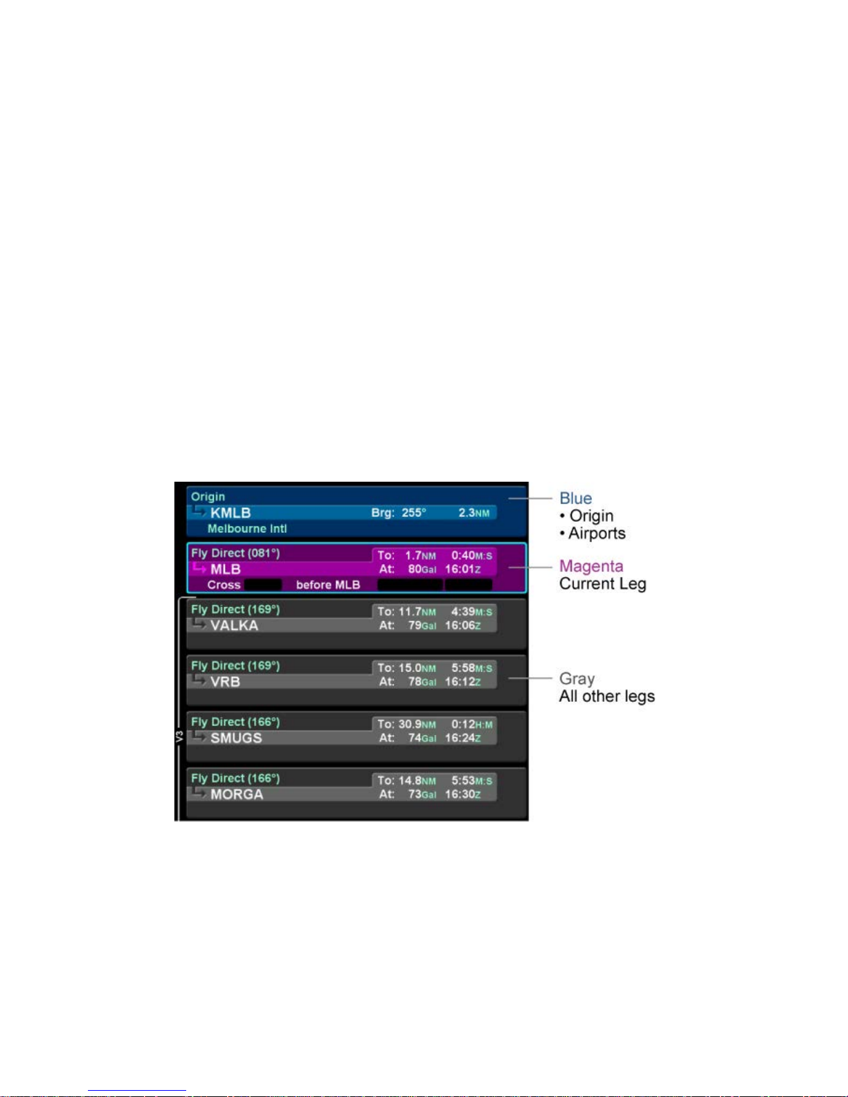
FMS BASIC CONC E PT S
Each leg of a flight plan has its own color-coded background
designed to make the overall flight plan easier to read at a
glance.
The origin and all airport waypoints are depicted with a blue
background. The active leg of the active flight plan is always
depicted with a magenta background. All other legs of a flight
plan are depicted with a gra y back ground.
Flight Plan Detail
There are two types of cursors – an insert cursor and an edit
cursor. Rotate the “FMS” knob in the lower right corner of the
keyboard to see the visual difference. The insert cursor will
appear as a thin blue horizontal line that appears between flight
plan legs. This allows you to insert new legs. The edit cursor
appears as a wrap-around blue box that encircles the entire leg
and allows you to edit an existing leg.

3-4 Ground Operations
Insert Cursor
Edit Cursor
Individual fields within a leg can be edited by rotating the “FMS”
knob that highlights each editable field within the flight plan.
When the desired field is highlighted with reverse video, push the
“FMS” knob to get into edit mode. Turn the knob as required to
edit the value or type via the keyboard, then push the knob again
to exit edit mode.
Using a combination of the push and rotation actions of the “FMS”
keyboard knob, along with the dropdown boxes, an entire flight
plan can be entered w ithin s ec onds.
CREATING A NEW FLIGHT PLAN
The first time the “Flight Plan” tab of the FMS page is accessed
on any given flight, an empty flight plan page is presented with
the origin waypoint pre-populated. The origin will be the closest
airport to the current GPS position, or the airport from the
previous power down if GPS position has not locked on yet.
In almost every case, your hand can stay on the “FMS” knob.
Through a combination of pushes and turns, you can enter the
entire flight plan.
Ground Operations 3-5
Flight Plan
COOL FEATURE
Geofill™ is a geographic-based prediction
algorithm that significantly reduces the number of
pilot actions for entering waypoints. Usually after the
first character entry, the system uses existing
characters to determine the closest, and most likely,
waypoint based on your geographic position or
existing flight plan.
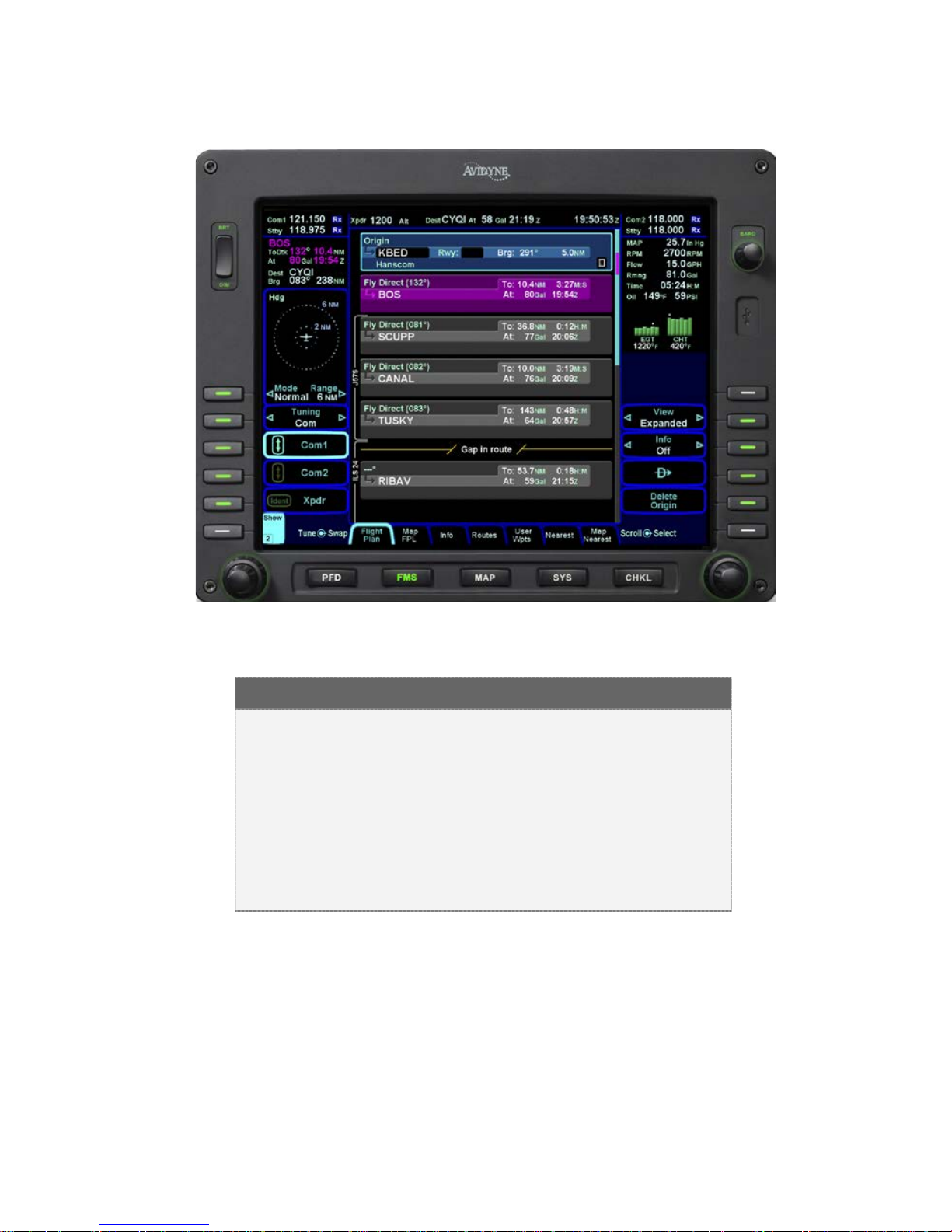
For those flight plans that have more legs than can be displayed
on a single page, a scroll bar is presented along the right edge of
the flight plan. It indicates w here the vi e wable windo w is with
respect to the entire flight plan as well as where the active leg in
the flight plan is. In the image above, the magenta vertical
rectangle in the scroll bar indicates the active leg is just below the

3-6 Ground Operations
origin. There are a number of flight plan legs out of sight below
the bottom of the display.
COOL FEATURE
Expanding and Compacting the Flight Plan The
“Flight Plan” tab of the FMS page provides a means
to show every leg of the flight plan (“Expanded”) or
an abbreviated version of the flight plan (“Compact”)
via the “View” LSK. The compact view hides all
intermediate legs of an airwa y between t he entry
and exit point. It also hides intermediate legs of
published departures, arrivals and approaches such
as step down fixes. The active procedure or airway
is always expanded.
ACTIVATING A FLIGHT PLAN
While you always have the option to manually activate the flight
plan via a LSK on the Flight Plan tab, the created plan on the
Flight Plan tab will automatically activate on takeoff roll when a
threshold groundspeed is achieved (which is approximately 40
knots). If you built the flight plan on the “Routes” tab, then you will
need to manually activate it via the “Activate Flight Plan” LSK on
the right side of the display.
SAVING/NAMING A FLIGHT PLAN
From the Routes tab of the FMS page, the current route, labeled
Current Route, will be highlighted in magenta. If a valid origin and
destination have been created in the flight plan (e.g. “KBED –
CYQI”), the title will include these.
To edit the name of a flight plan, use the outer ring of the right
bezel knob. Scroll up or down the flight plan list until the desired
flight plan is highlighted by a surround cursor. By pushing the
knob, the selected route will load and the route name field will be
shown in reverse video. Using the keyboard, type the desired
name. To accept the new route name press either the Enter LSK
or the Enter button on the keyboard.
 Loading...