

Avidyne DFC90 Pilot's Manual


Page Chg
Cover…...0
Page #.....3
TOC-1......3
TOC-2…..3
1-1………2
1-2……….3
1-3……….3
1-4……....3
1-5……....3
1-6…….…3
1-7…….…3
1-8…….…3
1-9…….…3
1-10……...3
1-11……..3
1-12……..3
1-13……..3
1-14……..3
1-15……..3
1-16……..3
1-17……..3
1-18……...3
1-19……..3
2-1……….0
2-2……….0
2-3……….3
2-4……….0
3-1……….2
Page Chg
3-2……….3
3-3……….3
3-4……….3
3-5……….3
3-6……….3
3-7……….0
3-8……….3
3-9……….0
3-10……..0
3-11……..0
3-12……..2
4-1……….2
4-2……….3
4-3……….3
4-4……….3
4-5……….3
4-6……….3
4-7……,…2
4-8…….…3
4-9……….3
4-10……...3
5-1……….2
5-2……….2
5-3……….2
5-4……….3
5-5……….3
5-6……….3
5-7……….3
Page Chg
5-8……….3
5-9……….2
5-10……..2
5-11……..3
5-12……..3
5-13……..2
5-14……..2
5-15……..2
5-16……..3
5-17……..3
5-18……..3
5-19……..3
5-20……..3
5-21……..3
5-22……..3
5-23……..3
5-24……..3
5-25……..3
5-26……..3
6-1……….3
6-2…….…3
6-3…….…3
6-4……….3
6-5…….…3
6-6……….3.
Indx-1…...3
IBC……....1
OBC…..…3
Change 3

1-2 System Overview
DFC90 Digital Autopilot | PILOT GUIDE
TABLE OF CONTENTS
1 System Overview ..............................................................1-2
FUNCTIONAL OVERVIEW ..........................................................1-3
GENERAL AUTOPILOT OPERATIONS .......................................1-4
Always a vertical and lateral mode engaged ......................................... 1-4
Single press to hold, Dual button press to capture ................................ 1-4
Primary location for bug/target setting ................................................... 1-5
Aural Alerts ........................................................................................... 1-5
Armed vs Engaged modes indications .................................................. 1-6
Mode transition indication ..................................................................... 1-7
Manual Electric Trim impact .................................................................. 1-7
Envelope Protection .............................................................................. 1-8
Full-Time Envelope Alerting ................................................................ 1-10
Baro Adjust ......................................................................................... 1-13
Engagement and Hold limits ............................................................... 1-14
Comparators ....................................................................................... 1-15
Autopilot Engagement ......................................................................... 1-16
Autopilot Disengagement .................................................................... 1-16
FD vs. AP ........................................................................................... 1-17
Dual PFD Operations .......................................................................... 1-18
PFD Annunciations ............................................................................. 1-19
2 Normal Startup Sequence ................................................2-2
POWER CONSIDERATIONS .......................................................2-2
SELF-TEST/ALIGNMENT ............................................................2-2
BRIGHTNESS CONTROLS .........................................................2-2
PRE-FLIGHT TEST ......................................................................2-3
BEFORE TAKEOFF TECHNIQUES .............................................2-4
3 Climb-out/Enroute .............................................................3-2
NORMAL OPERATING MODES ..................................................3-2
Pitch Mode ............................................................................................ 3-2
Roll Mode ............................................................................................. 3-2
Heading (HDG) Mode ........................................................................... 3-3
Navigation (NAV) Mode ........................................................................ 3-3
GPS Roll Steering (GPSS) Mode ................................ .......................... 3-4
Altitude Hold (ALT) Mode ...................................................................... 3-5
Indicated Airspeed (IAS) Hold Mode ..................................................... 3-5
Vertical Speed (VS) Hold Mode ............................................................ 3-6
Altitude Capture Mode .......................................................................... 3-6
Straight and Level ................................................................................. 3-9
Pilot Selectable Intercepts ................................................................... 3-10
Control Wheel Steering Mode ............................................................. 3-12
4 Approach Procedures ......................................................4-2
GENERAL BEHAVIOR .................................................................4-2
APPROACH MODES ...................................................................4-2
WAAS Approaches ............................................................................... 4-2
Non-WAAS GPS approach (RNAV or Overlay or LNAV) ....................... 4-5
VOR approach ...................................................................................... 4-5
Localizer approach ................................................................................ 4-6
Change 3

ILS approach including glide slope intercept ......................................... 4-7
Procedure Turn ILS or Localizers .......................................................... 4-9
Back course approaches ..................................................................... 4-10
Missed Approach ................................................................................ 4-10
5 Abnormal Procedures ......................................................5-2
GENERAL FAILURE MODE INFORMATION ...............................5-2
Loss of PFD Display (AHRS still Operational) ....................................... 5-3
Loss of PFD Bezel buttons and KNobs ................................................. 5-4
Loss of PFD Display and Bezel buttons ................................................ 5-5
Loss of Turn Coordinator ................................ ...................................... 5-6
Loss of AHRS (Single PFD Equipped Aircraft) ...................................... 5-7
Loss of AHRS (Dual Avidyne PFD Equipped Aircraft) ........................... 5-7
Loss of Air Data .................................................................................... 5-8
Total Loss of PFD (Single PFD Equipped Aircraft) ................................ 5-9
Total Loss of PFD (Dual PFD Equipped Aircraft) ................................... 5-9
Loss of Engine .................................................................................... 5-10
OTHER ERROR MODES ...........................................................5-11
General or Unknown Failures .............................................................. 5-11
AHRS-TC Miscompare during Ground Operations .............................. 5-12
Built-in Test (BIT) Failure .................................................................... 5-13
AHRS Aligning .................................................................................... 5-14
No Communication With Autopilot ....................................................... 5-15
Trimming Up/Down ............................................................................. 5-16
GPSS Invalid ...................................................................................... 5-17
Nav Invalid .......................................................................................... 5-18
Glide slope Invalid............................................................................... 5-19
TC Fail ................................................................................................ 5-20
AHRS Miscomp .................................................................................. 5-21
No PFD Comm ................................................................................... 5-22
MSR Fail ............................................................................................. 5-23
Audio Fail ............................................................................................ 5-24
Servo Limit .......................................................................................... 5-25
Bank Limit ........................................................................................... 5-26
6 Limitations and Performance ..........................................6-2
LIMITATIONS ...............................................................................6-2
SOFTWARE COMPATIBILITY AND NOTES ...............................6-2
GENERAL PERFORMANCE – CIRRUS AIRCRAFT ...................6-5
PERFORMANCE IN PITCH TRIM-ONLY AIRCRAFT ..................6-6
PERFORMANCE IN NON-CIRRUS AIRCRAFT...........................6-6
Index ............................................................................................ 1
Change 3


System Overview 1-1
1 System Overview ..............................................................1-2
FUNCTIONAL OVERVIEW ..........................................................1-3
GENERAL AUTOPILOT OPERATIONS .......................................1-4
Always a vertical and lateral mode engaged ......................................... 1-4
Single press to hold, Dual button press to capture ................................ 1-4
Primary location for bug/target setting ................................................... 1-5
Aural Alerts ........................................................................................... 1-5
Armed vs Engaged modes indications .................................................. 1-6
Mode transition indication ..................................................................... 1-7
Manual Electric Trim impact .................................................................. 1-7
Envelope Protection ................................................................ .............. 1-8
Full-Time Envelope Alerting ................................................................ 1-10
Baro Adjust ......................................................................................... 1-13
Engagement and Hold limits ............................................................... 1-14
Comparators ....................................................................................... 1-15
Autopilot Engagement ......................................................................... 1-16
Autopilot Disengagement .................................................................... 1-16
FD vs. AP ........................................................................................... 1-17
Dual PFD Operations .......................................................................... 1-18
PFD Annunciations ............................................................................. 1-19
Change 2

1-2 System Overview
1 System Overview
This manual assumes that the pilot is appropriately licensed, is
proficient in operation of the aircraft and its equipment, and is in
compliance with all Federal Aviation Regulations (FARs).
All images contained in this manual are for reference use only,
and are subject to change.
Avidyne strongly recommends that pilots use the DFC90 system
only under VFR conditions until completely familiar with its
operation and use.
Boxed areas marked as NOTE within this manual identify certain
situations or areas of operation having safety implications. While
it is important for the operator to be familiar with all of the
information in the manual, it is essential to the safe use of the
DFC90 that pilots give careful attention to the material contained
within these NOTEs.
Boxed areas marked as WARNING within this manual identify
certain situations or areas of operation having unique and
heightened safety implications.
In order to avoid a diversion of attention from the task of safely
taxiing, pilots should avoid performing the described cockpit tasks
while the aircraft is in motion. It remains the pilot’s duty to monitor
the autopilot for proper function upon activation and during use.
Note: For those aircraft that are not equipped with a 430-family GPS Nav-Com,
the Aspen PFD converts the signals such that the DFC90 should behave in
accordance with these descriptions. If the GPS or NAV does not support an input,
the Aspen PFD sends the input as invalid to the DFC90.
Internal DFC90 data logs are property of Avidyne.
DFC90 Digital Flight Control System
Change 3

System Overview 1-3
FUNCTIONAL OVERVIEW
The Avidyne DFC90 autopilot supports the following functions:
Flight Director
Heading Capture/Hold
NAV Tracking
GPSS Mode
Approach Mode (includes LOC, ILS, VOR, BC, LPV,
LNAV/VNAV, LNAV+V)
Altitude Hold
Altitude Capture
Vertical Speed Hold
Indicated Airspeed Mode
Straight and Level
Speed-based Envelope Protection (EP™)
Full-time Envelope Alerting (EA™) (requires Avidyne PFD
8.0.4 or later or Aspen PFD 2.6 or later)
Pilot Selectable Intercept Angles
Control Wheel Steering (not available in all aircraft)
NOTE
Envelope Protection vs. Envelope Alerting
There is a distinction between Envelope Protection
(EP™) and Full-time Envelope Alerting (EA™).
Envelope Protection (EP™) will result in active
driving of the flight control surfaces by the autopilot.
Full-time Envelope Alerting (EA™) will only provide
visual and aural alerting but it is up to the pilot to
manually make any control surface changes.
The term “LSK” is used throughout this manual. It is an
abbreviation for Line Select Key and is meant to describe the
buttons along the left/right edges of the PFD bezel.
Change 3

1-4 System Overview
GENERAL AUTOPILOT OPERATIONS
The Digital Flight Control (DFC) DFC90 autopilot has been
designed to be a retrofit digital autopilot. It requires an Avidyne
PFD (Release 8.0.2 or later PFD) or an Aspen EFD1000 PFD
(Release 2.6 or later Pilot Pro PFD).
In a DFC-equipped airplane, the autopilot uses the output of the
Air Data and Attitude-Heading Reference System (ADAHRS)
embedded in the PFD and is therefore an attitude-based
autopilot. A digital, attitude-based autopilot will be noticeably
more precise than the rate-based autopilot it is replacing.
As a rule, the pilot should not attempt to provide “active
assistance” to the autopilot by utilizing yoke controls, when
engaging the autopilot or while the autopilot is engaged in AP
mode.
ALWAYS A VERTICAL AND LATERAL MODE ENGAGED
The DFC90 autopilot has been designed to always have both a
lateral and vertical mode engaged. If a specific lateral mode has
not been selected by the pilot, then the system defaults to Roll
Hold mode. If a specific vertical mode has not been selected by
the pilot, then the system defaults to Pitch Hold mode.
SINGLE PRESS TO HOLD, DUAL BUTTON PRESS TO
CAPTURE
A single button press is typically required to engage a desired
mode, while a dual button press is typically required to capture a
new target. For example, to engage altitude hold, press ALT; to
engage heading hold, press HDG, to hold indicated airspeed,
press IAS. Likewise, to engage a vertical mode that will result in
capturing a new altitude, press both IAS and ALT or VS and ALT,
to capture a course, press both HDG and NAV, etc.
Change 3

System Overview 1-5
PRIMARY LOCATION FOR BUG/TARGET SETTING
The primary location for setting both the IAS and VS targets are
via the dedicated knobs on the autopilot control head.
The primary location for setting the HDG and ALT targets are via
line select keys and right-hand knob on the Avidyne PFD or the
right-hand knob on the Aspen PFD.
VS target can optionally be set via a line select key and righthand knob on the Avidyne or Aspen PFD. IAS target can
optionally be set via the left-hand knob on the Aspen PFD. Both
the VS and IAS targets stay synched between the two locations
for setting targets.
AURAL ALERTS
Aural alerting, through the aircraft intercom system, is provided
for warnings from the autopilot. Coupled describes the condition
when the autopilot servos are flying the airplane and non-coupled
describes the condition when the servos are not flying the
airplane and the pilot is expected to follow the flight director
command bars, if present. Specifically, aural alerts as defined in
the parenthesis are provided under the following conditions:
Autopilot Disengaged (approx 16 Disconnect beeps)
Underspeed during coupled operations (“Speed
Protection Active”)
Overspeed during coupled operations (“Speed Protection
Active”)
Underspeed during non-coupled operations (“Caution,
Underspeed”) [Not available in SIU-equipped Cirrus or
any Aspen configurations when flaps are set to full]
Overspeed during non-coupled operations (“Caution,
Overspeed”)
Attitude and Heading Reference System (AHRS) and
Turn Coordinator Miscompare (“Gyro Miscompare”)
POH bank limit exceeded (“Caution, Excessive Bank”)
POH 1st notch flap limit exceeded (“Caution, Flap
Overspeed”) [requires flap wiring during installation]
Change 3
1-6 System Overview
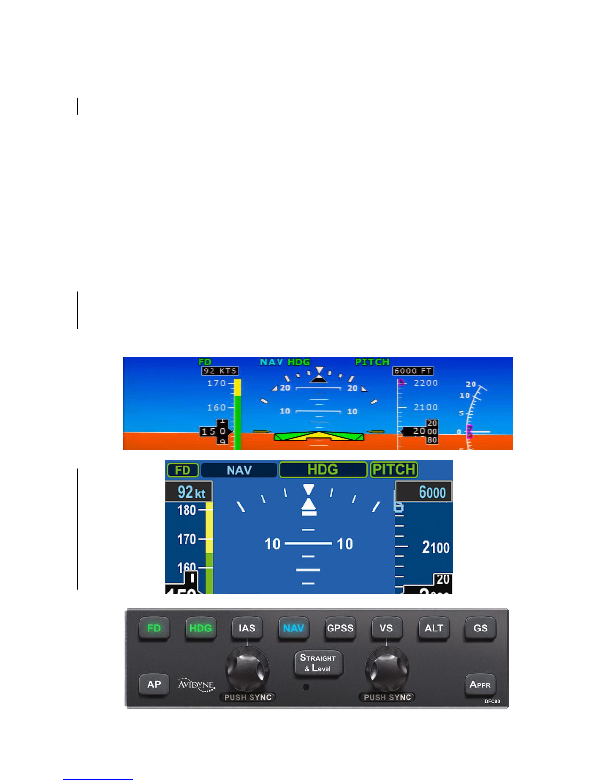
ARMED VS ENGAGED MODES INDICATIONS
The DFC-series of autopilots has readily distinguishable armed
vs. engaged modes in order to provide the user higher awareness
of the current autopilot state and upcoming state transitions.
An armed mode is defined as a state that will be captured when
and if the airplane crosses that target. Armed modes are
indicated by a cyan (blue) color on both the autopilot control
panel and on the PFD mode annunciator strip.
An engaged mode is defined as a state that the autopilot is
holding. Engaged modes are indicated by a green color on both
the autopilot control panel and on the PFD mode annunciator
strip.
The images below (Avidyne on top and Aspen in the middle)
demonstrate the armed and engaged coloring on both the
displays and the autopilot control head. In this example, Heading
(HDG) and Pitch modes are engaged and Nav mode is armed.
Change 3

System Overview 1-7
MODE TRANSITION INDICATION
Automatic transition from armed (cyan) to engaged (green) states
is indicated by the cyan armed button on the autopilot control
panel and mode annunciation on the PFD changing to green and
flashing for up to 10 seconds.
Note that the engaged (green) autopilot mode annunciators will
also flash when in underspeed or overspeed conditions. This
flashing is intended to gain the pilot’s attention and to indicate
that while the modes are still engaged (green), the underspeed or
overspeed condition may be affecting the system’s ability to hold
the target value. As soon as the underspeed or overspeed
condition is no longer true, the annunciators stop flashing and the
system reacquires the target values as required.
MANUAL ELECTRIC TRIM IMPACT
Any attempt to engage manual electric trim (MET) via the cockpit
controls will result in the autopilot disconnecting and then the trim
running as commanded by the MET control.
NOTE
Trim Behavior in DFC90-equipped Aircraft
For some aircraft (e.g. Cirrus), if the airplane is
equipped with a pitch servo, actuating the trim
switch will disconnect the AP. For some aircraft
(e.g. Cirrus) that are equipped only with pitch trim,
actuating the trim switch will have no effect during
autopilot operations (trim will not adjust and the AP
will not disengage). For predictability of results,
pilots of DFC90-equipped aircraft should therefore
determine whether the aircraft is equipped with a
pitch servo or pitch trim and the resulting behavior
before actuating the trim switch in IMC conditions.
Change 3

1-8 System Overview
ENVELOPE PROTECTION (EP™)
The DFC90 system provides speed-based Envelope Protection
(EP™) (underspeed and overspeed warnings and protection)
when in any coupled autopilot mode.
NOTE
No Envelope Protection in Flight Director Mode
Envelope Protection (EP™) is not provided during
flight director-only (non-coupled) operations.
NOTE
Aircraft Stall Possible with Envelope Protection
Conditions can exist where an aircraft can be placed
in an attitude and/or configuration that would exceed
the capability of the Envelope Protection (EP™)
system to prevent a stall.
When the servos are engaged (AP mode), the likelihood that a
command can be made which results in an autopilot induced stall
is significantly reduced over conventional autopilots. If for
example, a positive rate of climb was commanded and a low
power setting is being held, the autopilot will attempt to achieve
the commanded state but as the energy of the airplane decays to
approximately 1.2 Vs, the autopilot will adjust bank angle and then
pitch angle as required to maintain no lower than 1.2 Vs. Bank
angle may be reduced before pitch is adjusted in an effort to
avoid even entering Envelope Protection (EP™). As soon as
bank angle is adjusted by the autopilot, the pilot is alerted through
visual means on the PFD (“UNDERSPEED” text alert and any
engaged (green) autopilot mode annunciator will flash) and as
soon as pitch is adjusted, the pilot is alerted through the same
visual means on the PFD, and aural alerting in the headsets
(“SPEED PROTECTION ACTIVE”). In all cases, when
underspeed protection is active, maximum bank angle will be
reduced, typically to 5 degrees.
Change 3

System Overview 1-9
Similarly, Envelope Protection (EP™) will provide high-speed
protection and alerting near Vne. In this case, as Vne is
approached in AP mode, the autopilot will adjust pitch as required
to maintain an airspeed near Vne. Aircraft bank angle is not
adjusted by the autopilot during overspeed protection. Depending
on conditions (e.g. rapidly changing airspeed, turbulence, etc.), it
is possible for V
ne
to be exceeded. An overspeed condition is
annunciated to the pilot via an “OVERSPEED” text alert on the
PFD, a “SPEED PROTECTION ACTIVE” aural alert in the
headsets, and by a flashing of any engaged (green) autopilot
mode annunciators.
The DFC90 is capable of taking flap position into account in
Envelope Protection (EP™) and Envelope Alerting (EA™)
calculations and as a result, the definition of Vs, changes
depending on flap position in those aircraft with the flap wiring
installed. The use of this flap input is part of Avidyne’s Adaptive
Autopilot™ concept.
NOTE
Envelope Protection During Icing Conditions
The DFC90 autopilot is not to be used during icing
conditions. The autopilot does not have any kind of
AOA or icing input and therefore does not register
changing aircraft dynamics during icing conditions.
Therefore, Envelope Protection (EP™) is not
effective under icing conditions.
Change 3

1-10 System Overview
FULL-TIME ENVELOPE ALERTING (EA™)
NOTE
Envelope Alerting Requires Flap Input
For the underspeed Full-Time Envelope Alerting
(EA™) function to be available when the autopilot is
in standby (“AP Ready”), a wiring modification must
be made that allows the autopilot to recognize
actual flap position. Not accomplishing this wiring
modification to the aircraft harnessing means there
is no Full-time Envelope Alerting (EA™) for
underspeed conditions when the autopilot is in
standby mode. The underspeed Full-Time Envelope
Alerting (EA™) function is not available when flaps
are set to full in non-primary engine (“SIU”)
equipped Cirrus or any Aspen-equipped aircraft.
The DFC90 autopilot provides speed-based and attitude-based
envelope alerting when the autopilot is not engaged (servos not
coupled). [Requires Avidyne PFD Rel 8.0.4 or Aspen PFD v2.6
and DFC90 Rel 2 or later.]
Full-time Envelope Alerting (EA™) is triggered when the DFC90
recognizes an underspeed (Underspeed EA function is not
available in SIU-equipped Cirrus or any Aspen-equipped aircraft
when flaps are set to full), overspeed, flap overspeed or
excessive bank angle condition and will alert the pilot via text
alerts on the PFD and aural alerts.
Full-time Envelope Alerting (EA™) is provided during flight
director operations (servos not coupled). Full-time Envelope
Alerting (EA™) is also provided (underspeed requires the flap
wiring modification) even when the autopilot and flight director are
off and the autopilot is in the standby position as noted by the AP
READY mode annunciator on the top strip of the PFD.
Change 3

System Overview 1-11
NOTE
Suppression of Full-time Envelope Alerting
Full-time Envelope Alerting (EA™) is suppressed
during very low power (near idle) conditions when
flaps are set to the full-flap position in order to
minimize nuisance calls in the landing phase. Fulltime Envelope Alerting (EA™) is also suppressed
anytime Indicated Airspeed is less than 50 KIAS.
In Flight Director operations, the flight director command bars will
continue to direct a pilot to fly to the commanded pitch and roll
targets as defined by the bug and nav source entries but if an
underspeed condition is recognized, a “UNDERSPEED” text alert
is displayed on the PFD and a “CAUTION, UNDERSPEED” aural
alert is played in the headsets and is repeated approximately
every 6 seconds until the condition is no longer valid. The
autopilot mode annunciators do not flash during Envelope
Alerting* (EA™). The trigger for this Envelope Alerting (EA™)
underspeed alert is when the system has determined 1.2Vs has
been reached. Flap position, bank angle and g-loading are taken
into account to define Vs at any point in time (assumes max gross
weight).
Similarly, during high-speed flight director operations, the flight
director command bars will continue to direct a pilot to fly to the
commanded pitch and roll targets as defined by the bug and nav
source entries but if an overspeed condition is recognized, a
“OVERSPEED” text alert is displayed on the PFD and a
“CAUTION, OVERSPEED” aural alert is played in the headsets
and is repeated approximately every 6 seconds until the condition
is no longer valid. There is no flashing of any autopilot mode
annunciator during Envelope Alerting (EA™).* The trigger for this
Envelope Alerting (EA™) overspeed alert is when the system
has determined Vne is about to reached.
If the autopilot is not engaged in any Autopilot or Flight Director
modes and is in the standby condition, as indicated by the green
“AP READY” annunciator on the PFD and no green or cyan lights
on the autopilot control head, Full-time Envelope Alerting (EA™)
is still active. In this case, there are no flight director command
Change 3

1-12 System Overview
bars present and no autopilot mode annunciators aside from the
“AP READY” one along the top edge of the PFD.
If an underspeed condition is recognized, an “UNDERSPEED”
text alert is displayed on the PFD and a “CAUTION,
UNDERSPEED” aural alert is played in the headsets and is
repeated approximately every 6 seconds until the condition is no
longer valid. The trigger for this Envelope Alerting (EA™)
underspeed alert is when the system has determined 1.2Vs has
been reached. Flap position, bank angle and g-loading are taken
into account to define Vs at any point in time. One common
scenario this capability is designed to alert against is a traffic
pattern stall.
Similarly, on the high-speed end of the spectrum with the
autopilot in the standby condition (green “AP READY” along the
top strip of the PFD pages), if an overspeed condition is
recognized, a “OVERSPEED” text alert is displayed on the PFD
pages and a “CAUTION, OVERSPEED” aural alert is played in
the headsets and is repeated approximately every 6 seconds until
the condition is no longer valid. The trigger for this Envelope
Alerting (EA™) overspeed alert is when the system has
determined Vne is about to reached.
If at any time and in any flight director or standby state, the
system detects an excessive bank condition, a “BANK LIMIT”
text alert is displayed on the PFD pages and a “CAUTION,
EXCESSIVE BANK” aural alert is played in the headsets and is
repeated approximately every 6 seconds until the condition is no
longer valid. The trigger for this Envelope Alerting (EA™)
excessive bank limit is when the system has determined that the
lesser of aircraft category or aircraft POH bank angle limits has
been exceeded. This number is typically 60 degrees of bank.
Finally, for those aircraft with the optional flap input to the
autopilot, if the autopilot system detects a flap overspeed
condition per POH flap deployment speed limitations, a
“CAUTION, FLAP OVERSPEED” aural alert is played in the
headsets and is repeated approximately every 6 seconds until the
condition is no longer true. There is no associated text alert.
If “AP READY” or “FD” are not displayed on the PFD page, Fulltime Envelope Alerting (EA™) may not be available.
Change 3

System Overview 1-13
To disable Full-time Envelope Alerting (EA™), pull the autopilot
circuit breaker.
(* In cases of pre-Rel 8.0.4 Avidyne PFD code combined with post-Rel 2 DFC90
code, the active (green) autopilot mode annunciators will flash during Underspeed
conditions. This is a normal consequence of maintaining backward compatibility.)
BARO ADJUST
Upon input of a new barometric altimeter setting, the autopilot
automatically re-captures the previously set target altitude,
without further action required from the pilot. In other words, if
the autopilot was in Altitude Hold for example, changing the
barometric pressure setting will result in the autopilot
automatically correcting the appropriate amount to re-capture the
previous MSL altitude hold target.
Change 3

1-14 System Overview
ENGAGEMENT AND HOLD LIMITS
The DFC90 has maximum engagement limits beyond which the
autopilot may not allow a mode to be selected, and maximum
hold limits for various parameters. The engagement limits of the
autopilot are wider than the hold limits. If the autopilot is engaged
between the maximum engagement limits and the maximum hold
limits, the autopilot will reduce the value to be within the
published maximum hold limits. (* value may vary with airframe)
The maximum engagement and hold limits are as follow:
Autopilot Mode
Maximum
Demonstrated
Engagement Limits
Maximum
Hold Limits
Roll Hold
±60 bank
±22 bank
Heading
±60 bank
±22 bank (but
typically holds 1
standard rate of turn)
Pitch Hold
±30 pitch
±10 pitch
IAS Hold
20 KIAS to Vne
1.2Vs to 185* KIAS
VS Hold
±1600 fpm
±1600 fpm
Straight and
Level
±60 bank, ±30 pitch
Will stabilize in +2
pitch and zero bank
angle
Localizer, VOR,
GPS approach
Capture
Not Applicable
±22 bank
Localizer, VOR,
GPS approach
Track
Not Applicable
±10 bank
Change 3

System Overview 1-15
COMPARATORS
The DFC90 autopilot is always running comparators in the
background. There are several types of comparators running
during operation of the autopilot as noted in the chart below. If
conflicting information is provided, the comparator identifying the
conflict with the accompanying pilot indication and autopilot
behavior is noted in the table below:
Type of
Comparator
Indication to Pilot
Autopilot behavior
Internal kinematic
comparator within
the AHRS
(compares AHRS
state data with
itself, eg. turn rate
without
accompanying
heading change,
etc)
“CROSSCHECK
ATTITUDE”
annunciation on
PFD for minor
issues and indicator
removal and
replacement by
“Red-X” for major
issues
No change for
“Crosscheck
Attitude” conditions
and potential
disconnect for RedX conditions
AHRS-to-Turn
Coordinator (TC)
Comparator [only
applicable for Cirrus
SR2x or Piper PA46
aircraft in which the
DFC90 is replacing
a STec 55X,]
Miscompare Alert
message(s)
presented to the
pilot on the PFD
(“AHRS
MISCOMP”) and in
the headset
(“GYRO
MISCOMPARE”)
Autopilot will not
disconnect if the
condition is
experienced in
flight. If the AHRSTC miscompare
condition was
present after initial
ground power-up,
the autopilot will be
prevented from
engaging in any
modes.
Change 3

1-16 System Overview
AUTOPILOT ENGAGEMENT
From a standby state (autopilot has power, “AP READY”
displayed but no modes are engaged and the airplane is within
the engagement limits defined above), pressing any button on the
autopilot will engage the DFC autopilot. If a specific lateral and/or
vertical mode is not pressed, the system will default to ROLL hold
mode in the lateral channel and PITCH hold mode in the vertical
channel.
From a standby state:
Press “AP” autopilot (servos coupled) engages in
ROLL and PITCH and will hold whatever bank and pitch
was present at time of pressing (assuming within
command limits)
Press “FD” flight director (servos not coupled) engages
in ROLL and PITCH and will command via the green
flight director command bars whatever bank and pitch
was present at time of pressing (assuming within
command limits). It is still up to the pilot to maneuver the
plane as required to follow those command bars.
Press “STRAIGHT & LEVEL” autopilot (servos
coupled) engages and drives the airplane from whatever
attitude it is in to zero bank and a small positive pitch that
approximates level flight.
Press any other button(s) on the autopilot autopilot
(servos coupled) engages and will enter the modes as
commanded.
AUTOPILOT DISENGAGEMENT
The autopilot can be disengaged using any one of the following
methods:
Press the AP Disconnect switch on the control yoke (in
some aircraft, this is a dedicated button and in others, it
requires a push in of the trim hat on the yoke);
Activate the pitch-axis trim switch on the control yoke
(this does not apply on pitch trim-only aircraft);
Change 3

System Overview 1-17
Press the “AP” button on the autopilot control panel
(servos will disconnect but the flight director will remain
active);
Pull the circuit breaker(s) controlling the power to the
autopilot.
For those aircraft with the stall warning wired directly to the
autopilot, the autopilot will also disconnect if the stall warning
alarm is present in the aircraft.
In most cases, the autopilot disconnect will be accompanied by a
16-beep disconnect aural alert. This tone can be muted by
pressing the AP Disconnect switch on the control yoke.
FD vs. AP
The status of the reference bugs, autopilot annunciators, autopilot
control head, and flight director steering command bars indicate
when the PFD is coupled with the autopilot.
A solid magenta heading, altitude, IAS or VS bug indicates that
function is currently coupled to an engaged or armed mode of the
autopilot or the flight director. A hollow magenta bug indicates
that the function is not currently coupled to the autopilot or flight
director in an engaged or armed mode. In other words, the
autopilot and flight director, are ignoring any hollow magenta bug.
The flight director command bars will indicate the required
steering of the aircraft to achieve the commanded tracking of the
autopilot. In full autopilot mode, both the “AP” and “FD” buttons
will be lit on the autopilot control panel and “AP” will be displayed
in the autopilot annunciation field on the display, the command
bars will be visible and magenta and the aircraft should track
those bars very precisely.
In Flight Director only mode, only the “FD” button (and not the
“AP” button) will be lit on the autopilot control panel and “FD” will
be displayed in the autopilot annunciation field on the display, the
command bars will be visible and green, and the pilot is expected
to use the flight controls as required to track those bars. In Flight
Director only mode, the pilot is hand flying the airplane and is
expected to guide the aircraft such that the yellow aircraft
reference symbol is tucked into the steering command bars.
Change 3

1-18 System Overview
The flight director command bars in a DFC90 autopilot are
designed for easy use and improved performance during
uncoupled autopilot operations.
During coupled operations (both “AP” and “FD” buttons lit),
pressing the “FD” button will have no effect. Pressing the “AP”
button in this state will toggle the “AP” mode on/off. It is a good
way to disconnect the servos but continue to have flight director
command bars present. The recommended way to disengage
both the “AP” and “FD” modes will be via trim or the AP
Disconnect switch on the control yoke as described above.
DUAL PFD OPERATIONS
For those aircraft equipped with dual Avidyne PFDs, either PFD
can drive the DFC90 however; it requires a manual action on the
part of the pilot to select the right-hand PFD to be the attitude and
air data source for the autopilot. There is not an automatic
switchover capability to the right-hand PFD in the event of an
inoperative left-hand PFD. The ADAHRS source selection switch
on the instrument panel must be toggled by the pilot to the righthand PFD.
For dual Avidyne PFD equipped aircraft that also are equipped
with a Pilot Priority switch on the instrument panel as described in
the Avidyne PFD Pilot Guide, selecting the Uncoupled option will
have no affect on the DFC90.
A PFD-to-PFD Miscompare will have no affect on the DFC90 in
dual-Avidyne PFD equipped aircraft. In these aircraft, the DFC90
is still using the AHRS-Turn Coordinator comparator and not the
PFD-PFD comparator.
If manually transitioning from an Altitude Capture to Altitude Hold
mode in dual-PFD equipped aircraft, it may be necessary to press
the ALT button on the DFC90 control panel a second time in preRelease 8.0.6 systems.
Change 3
System Overview 1-19
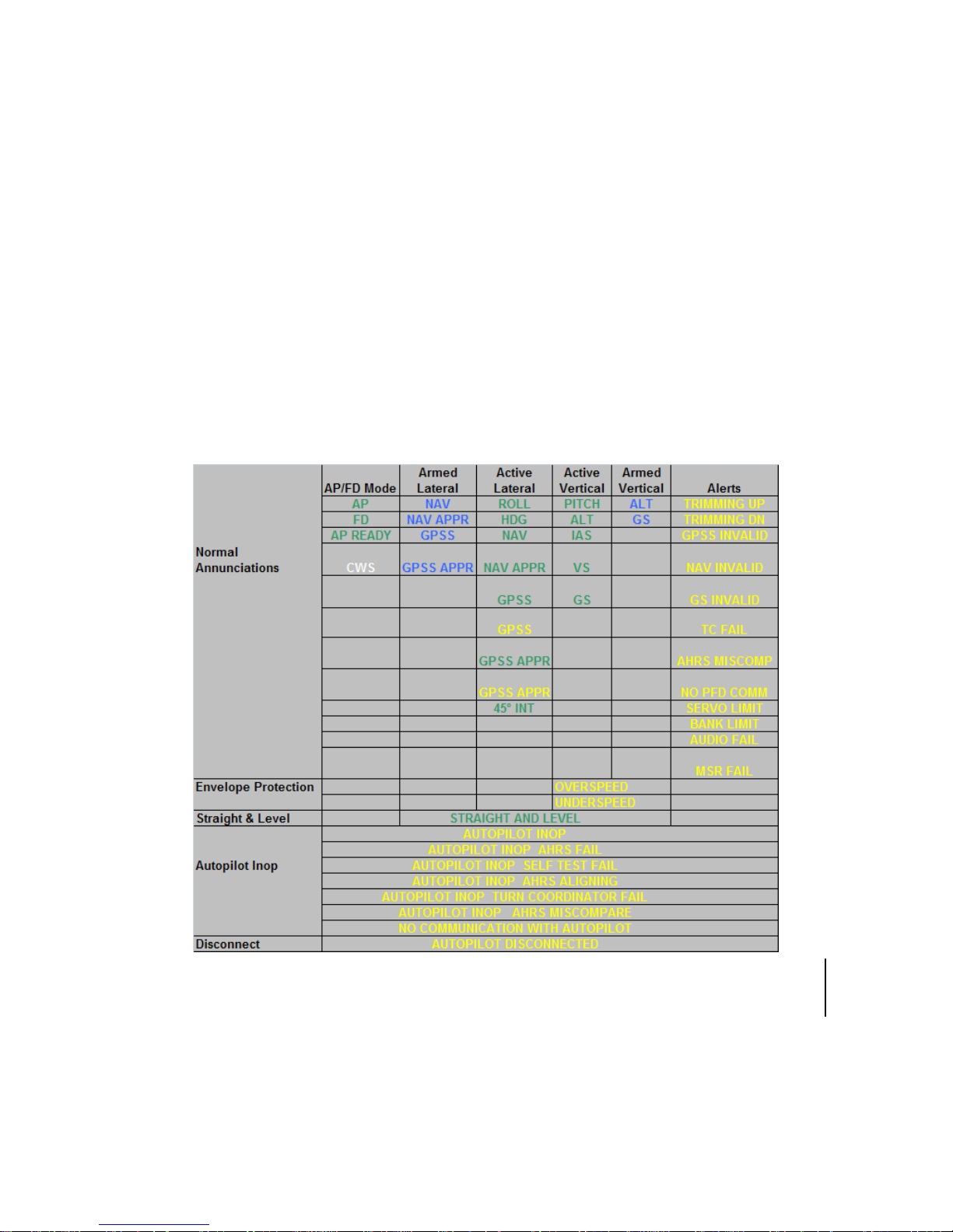
PFD ANNUNCIATIONS
The top strip of the PFD is dedicated for autopilot mode
annunciators. Active modes are depicted in green and armed
modes are depicted in cyan. Alerts are depicted in yellow and
are listed in order of priority. If multiple alerts are received, then
the highest priority message is displayed.
Whenever “UNDERSPEED” or “OVERSPEED” are displayed
while the autopilot is coupled, all engaged (green) autopilot mode
annunciators will flash.
The tables below are a listing of all annunciations that are
possible with the DFC90 system.
DFC90 Annunciations
Note: In Aspen PFD equipped aircraft, “AP READY” is shortened
to “AP RDY”.
Change 3


Normal Startup Sequence 2-1
2 Normal Startup Sequence ................................................2-2
POWER CONSIDERATIONS .......................................................2-2
SELF-TEST/ALIGNMENT ............................................................2-2
BRIGHTNESS CONTROLS .........................................................2-2
PRE-FLIGHT TEST ......................................................................2-3
BEFORE TAKEOFF TECHNIQUES .............................................2-4

2-2 Normal Startup Sequence
2 Normal Startup Sequence
POWER CONSIDERATIONS
The DFC90 consumes 0.25A when no servos are in operation
and up to 0.9A with all servos operating at 100% duty cycle.
There is no on/off switch to the DFC-series of autopilots. As soon
as the governing power bus is active through normal aircraft
checklist steps, the autopilot will power up.
SELF-TEST/ALIGNMENT
The DFC autopilot requires two events to be fully functional. The
first is a successful completion of a self-test and the second is a
successful alignment of the ADAHRS. To assure readiness of the
autopilot for flight, it is also recommended that the pilot conduct
the Pre-Flight Test described later in this chapter.
DFC self-test takes less than 5 seconds following power
application. The normal self-test indications are a lighting of
lights on the autopilot control panel, dwelling approximately 1-2
seconds on each color. The lighting color order is White-CyanGreen-White. Self-test should be considered a success after the
button lighting with no associated failure message along the top
strip of the PFD.
The top strip of the PFD will display an annunciation that the
autopilot is INOP (inoperative) while the ADAHRS is aligning.
The message will explicitly state that the ADAHRS is aligning.
Any other anomaly during alignment is displayed as a descriptive
annunciation along that same top annunciator strip on the PFD.
BRIGHTNESS CONTROLS
The autopilot control head button and knob lighting is controlled
via the cockpit dimming controls/rheostats.
If the autopilot control panel appears “inoperative” or nonresponsive from a lighting perspective, check the instrument
lighting rheostat on the bolster to ensure it is not set to a night
position.
 Loading...