

Avidyne AXP340 MODE S Installation Manual
AXP340 MODE S TRANSPONDER
INSTALLATION MANUAL

AXP340 Transponder Installation Manual 10 March 2014
01201-00 Issue AF
______________________
AVIDYNE CORPORATION i
This document is applicable to the Avidyne AXP340 Mode S Transponder.
For technical support, please contact Avidyne using the following information.
888-723-7592
781-402-7592
techsupport@avidyne.com
All materials copyrighted, including images that represent this software.
Copyright 2013 Trig Avionics Limited.
Parts of this document Copyright 2013 Avidyne Corporation.
All rights reserved.
The latest installation manuals are available to authorized dealers on the web at
www.avidyne.com.

AXP340 Transponder Installation Manual 10 March 2014
01201-00 Issue AF
______________________
ii AVIDYNE CORPORATION
CONTENTS
1. PREFACE ....................................................................................................................................... 1
1.1 PURPOSE .................................................................................................................................... 1
1.2 SCOPE ........................................................................................................................................ 1
1.3 CHANGES FROM PREVIOUS ISSUE .............................................................................................. 1
1.4 DOCUMENT CROSS-REFERENCES .............................................................................................. 1
2. INTRODUCTION .......................................................................................................................... 2
2.1 AXP340 DESCRIPTION .............................................................................................................. 2
2.2 INTERFACES ............................................................................................................................... 2
3. TECHNICAL SPECIFICATIONS ............................................................................................... 4
3.1 REGULATORY ............................................................................................................................ 4
3.1.1 Approved Deviations ........................................................................................................ 4
3.2 PHYSICAL SPECIFICATIONS (IN TRAY)........................................................................................ 4
3.3 INSTALLATION APPROVAL ......................................................................................................... 5
3.4 TSO FAILURE CONDITION CLASSIFICATION ............................................................................... 5
3.5 NON – TSO FUNCTIONS............................................................................................................. 5
4. UNIT AND ACCESSORIES SUPPLIED ..................................................................................... 6
4.1 AXP340 MODE S TRANSPONDER ITEMS ................................................................................... 6
4.2 MOUNTING TRAY, INSTALLATION KIT ........................................................................................ 6
4.3 DOCUMENTATION ...................................................................................................................... 6
4.4 REQUIRED ITEMS ....................................................................................................................... 6
5. INSTALLATION ............................................................................................................................ 8
5.1 UNPACKING AND INSPECTING EQUIPMENT ................................................................................ 8
5.2 MOUNTING ................................................................................................................................ 8
5.3 COOLING REQUIREMENTS .......................................................................................................... 8
5.4 ELECTRICAL CONNECTIONS ....................................................................................................... 8
5.4.1 Primary Interface – Pinout ............................................................................................... 9
5.4.2 Secondary Interface - Pinout .......................................................................................... 10
5.4.3 Orientation Diagram ...................................................................................................... 10
5.5 INTERFACE DETAILS ................................................................................................................ 11
5.5.1 Power Input .................................................................................................................... 11
5.5.2 Lighting Bus Input .......................................................................................................... 11
5.5.3 Mutual Suppression ........................................................................................................ 11

AXP340 Transponder Installation Manual 10 March 2014
01201-00 Issue AF
______________________
AVIDYNE CORPORATION iii
5.5.4 Altitude Inputs and Output ............................................................................................. 11
5.5.5 Squat Switch Input ................................................................................................ .......... 12
5.5.6 Ident Switch Input ........................................................................................................... 12
5.5.7 External Standby Input ................................................................................................... 12
5.5.8 Audio Output .................................................................................................................. 12
5.5.9 Altitude Alerter Output ................................................................................................... 13
5.5.10 GPS Position Input ......................................................................................................... 13
5.6 MOLEX CRIMP TERMINALS ...................................................................................................... 14
5.7 ANTENNA INSTALLATION......................................................................................................... 15
5.7.1 Antenna Cable ................................................................................................................ 15
5.7.2 BNC Connector ............................................................................................................... 17
5.8 TRAY / BNC CONNECTOR ASSEMBLY ..................................................................................... 19
6. INSTALLATION SETUP AND TEST ....................................................................................... 20
6.1 CONFIGURATION ITEMS ................................................................................................ ........... 20
6.1.1 Aircraft Registration ....................................................................................................... 20
6.1.2 Aircraft Address Programming ...................................................................................... 20
6.1.3 VFR Squawk Code ................................................................................................ .......... 21
6.1.4 Airspeed Category .......................................................................................................... 21
6.1.5 Aircraft Category ............................................................................................................ 21
6.1.6 Squat Switch Source ....................................................................................................... 21
6.1.7 GPS Input ....................................................................................................................... 21
6.1.8 GPS Line Speed .............................................................................................................. 21
6.1.9 GPS System Certification Level ...................................................................................... 21
6.1.10 GPS NACv ...................................................................................................................... 22
6.1.11 Aircraft Length and Width .............................................................................................. 22
6.1.12 GPS Antenna Offset ........................................................................................................ 22
6.1.13 ADS-B Receiver Options ................................................................................................. 22
6.1.14 Audio Volume ................................................................................................................. 22
6.1.15 Pressure Altitude Units ................................................................................................... 22
6.1.16 Lighting Control ............................................................................................................. 23
6.1.17 LCD Dim Point ............................................................................................................... 23
6.1.18 LCD Brightness .............................................................................................................. 23
6.2 TEST ITEMS .............................................................................................................................. 23
6.2.1 Interface Check ............................................................................................................... 23
6.2.2 Altitude Check ................................................................................................................. 23

AXP340 Transponder Installation Manual 10 March 2014
01201-00 Issue AF
______________________
iv AVIDYNE CORPORATION
6.2.3 Lighting Bus .................................................................................................................... 23
6.2.4 Temperature .................................................................................................................... 23
6.2.5 GPS Interface ................................................................................................................. 24
7. POST INSTALLATION CHECKS ............................................................................................. 25
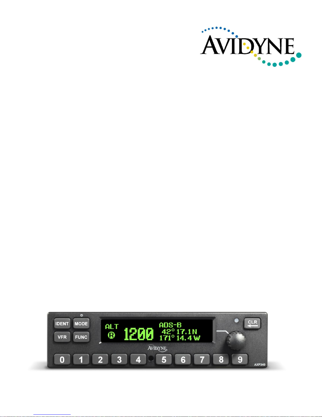
8. NORMAL OPERATION ............................................................................................................. 26
8.1 OVERVIEW ............................................................................................................................... 26
8.2 FRONT PANEL .......................................................................................................................... 26
8.3 DISPLAY .................................................................................................................................. 26
8.4 POWER ON/OFF ................................................................................................................... 26
8.5 MODE CONTROL ................................................................................................................. 26
8.6 IDENT .................................................................................................................................... 27
8.7 VFR ........................................................................................................................................ 27
8.8 FUNC ..................................................................................................................................... 27
8.9 SELECTOR KNOB ..................................................................................................................... 27
8.10 NUMERIC BUTTONS ................................................................................................................. 27
8.11 CLR ........................................................................................................................................ 27
8.12 SQUAWK CODE ENTRY ............................................................................................................. 27
8.13 FLIGHT TIMER ......................................................................................................................... 28
8.14 STOPWATCH ............................................................................................................................ 28
8.15 FLIGHT ID ENTRY .................................................................................................................... 28
8.16 ALTITUDE MONITOR ................................................................................................................ 28
8.17 ADS-B MONITOR .................................................................................................................... 28
8.18 ALERT MESSAGES ................................................................................................................... 28
8.19 FAULT ANNUNCIATION ................................................................ ................................ ............ 29
8.20 LOW TEMPERATURE OPERATION ............................................................................................. 29
9. CONTINUED AIRWORTHINESS............................................................................................. 30
10. ENVIRONMENTAL QUALIFICATION FORM ................................................................. 31
11. ADS-B COMPLIANCE............................................................................................................ 33
11.1 ADS-B PARAMETERS SUPPORTED ........................................................................................... 33
11.2 FAA 91.227 COMPLIANCE ....................................................................................................... 33
11.3 AMC 20-24 COMPLIANCE ....................................................................................................... 33
11.4 AUTOMATIC AIR/GROUND DETERMINATION ........................................................................... 33
11.5 ADS-B SUPPORT ..................................................................................................................... 33

AXP340 Transponder Installation Manual 10 March 2014
01201-00 Issue AF
______________________
AVIDYNE CORPORATION v
12. INSTALLATION DRAWINGS ............................................................................................... 35
13. BASIC INTERCONNECT DIAGRAM .................................................................................. 36
14. AVIDYNE EXCLUSIVE LIMITED WARRANTY AND LIMITATIONS ON LIABILITY37
15. SOFTWARE LICENSE ........................................................................................................... 39

AXP340 Transponder Installation Manual 10 March 2014
01201-00 Issue AF
______________________
vi AVIDYNE CORPORATION
This page intentionally left blank

AXP340 Transponder Installation Manual 10 March 2014
01201-00 Issue AF
AVIDYNE CORPORATION Page 1
1. Preface
1.1 Purpose
This manual describes the physical and electrical characteristics and the installation requirements for an
AXP340 Mode S Transponder.
1.2 Scope
This document applies to the installation of the AXP340 Mode S Transponder.
At the publication date of this manual the software version identifier for the AXP340 is 3.8 and the FPGA
version identifier is 110613a. The software and FPGA versions are subject to change without notice.
1.3 Changes from Previous Issue
Updated section 4 to reflect the Avidyne part numbers and kit combinations
Corrected version numbering for updated documents
Added KT76C to the list of equivalent transponder trays
Added statement in 6.1.1 about automated Mode S address generation for N reg. aircraft
1.4 Document Cross-References
600-00302-000
AXP340 Mode S Transponder Pilot Guide
02

AXP340 Transponder Installation Manual 10 March 2014
01201-00 Issue AF
Page 2 AVIDYNE CORPORATION
2. Introduction
2.1 AXP340 Description
The AXP340 Mode S panel mount transponder is an ED-73E and DO-181E Class 1 compliant Mode S
level 2es datalink transponder, with support for extended squitter, elementary surveillance and SI codes.
The AXP340 is also a DO-260B Class B1S compliant ADS-B out participant. The AXP340 meets the
relevant environmental requirements of DO-160G/ED-14G, and is certified to ETSO C112d, ETSO C166b,
TSO C112d and TSO C166b.
The AXP340 transmitter power output is nominally 240 watts, and the transponder runs from either 14 volt
nominal or 28 volt nominal DC power supply with no configuration changes required.
The AXP340 transponder responds to both legacy Mode A/C interrogations and to Mode S interrogations
from both ground radar and airborne collision avoidance systems. In all cases, the interrogations are
received by the transponder on 1030MHz, and replies are transmitted on 1090MHz.
In the Mode S environment, S stands for Select, and a Mode S interrogator can selectively address a single
transponder. This allows accurate position plotting with lower reply rates, which in turn reduces frequency
congestion and interference. As a side benefit, power consumption by the transponder may be reduced, and
simple datalink services can be supported, such as ADS-B. It is however crucial to the reliable operation of
the system that each aircraft has a distinct Mode S address. The Mode S address is allocated by the
registration authority for the aircraft, and must be set when the AXP340 is installed.
2.2 Interfaces
At the rear, the transponder has two Molex style connectors and a single antenna connector for blind mating
with the corresponding connectors in the mounting tray.
The interfaces provide the following services:
Parallel altitude input
Connection to an external altitude encoder using parallel Gray code.
Serial altitude input
Connection to an external RS232 altitude encoder or air data computer. Using
serial altitude data allows the transponder to report altitude with 25 foot
resolution.
Serial altitude output
Connection to a GPS or other device needing serial altitude data – this allows the
transponder to act as a repeater instead of requiring a second altitude encoder.
Ident input
External IDENT switch input.
Standby input
External standby input for dual transponder installations.
“On ground” input
Allows automatic flight/ground mode switching for aircraft with a squat switch.
Lighting bus input
Used to adjust the backlight and switch lighting intensity.
DME Suppression
Input
Input to limit interference between DME interrogations and transponder replies –
suppresses transponder whilst active.
Suppression bus I/O
ARINC compatible suppression bus signal used in aircraft with more sophisticated
suppression needs, both an input to and output from the transponder.
Audio output
Optionally used by the altitude monitor function.
Audio mute input
Toggle function to mute the audio output.

AXP340 Transponder Installation Manual 10 March 2014
01201-00 Issue AF
AVIDYNE CORPORATION Page 3
Altitude alert output
Output used to signal altitude deviations when optional altitude monitor function
is used.
GPS Input
Connection to a GPS supplying position input for ADS-B position reporting.

AXP340 Transponder Installation Manual 10 March 2014
01201-00 Issue AF
Page 4 AVIDYNE CORPORATION
3. Technical Specifications
3.1 Regulatory
Specification
Characteristics
Compliance
ETSO C112d, TSO C112d; Class 1 Level 2es
ETSO C166b, TSO C166b; Class B1S
FCC Identification
VZI01155
Applicable documents
EUROCAE ED-73E (RTCA DO-181E),
EUROCAE ED-14G (RTCA DO-160G) , RTCA DO-260B
with Corrigendum 1
Software
ED-12B (RTCA DO-178B) Level B
Power Requirements
10 – 33 Volts DC. Typical 6.3Watts @ 14Volts.
Altitude
55,000 feet
Humidity
95% @ +50C for 6 hours; 85% @ +38C for 16 hours.
Tested to Category A in DO-160G
Operating Temperature
-25C to +70C
Transmitter Frequency
1090MHz ± 1MHz
Transmitter Power
240 Watts nominal; 125 Watts minimum at antenna after
allowing for 0.5dB connector losses and 1.5dB cable losses.
Transmitter Modulation
6M75 V1D
Receiver Frequency
1030 MHz
Receiver Sensitivity
-74dBm ± 3dB
3.1.1 Approved Deviations
The AXP340 ADS-B function is certified to ETSO C166b which references DO-260B as the applicable
standard. Since publication of DO-260B a corrigenda has been published; the AXP340 complies with the
corrected DO-260B which technically is a deviation from the ETSO. This deviation has been approved by
EASA.
3.2 Physical Specifications (in Tray)
Specification
Characteristics
Height
42mm (1.65”)
Width
160mm (6.30”)
Length
285mm (11.22”)
Weight
2.8lbs. (1.35Kg)

AXP340 Transponder Installation Manual 10 March 2014
01201-00 Issue AF
AVIDYNE CORPORATION Page 5
3.3 Installation Approval
The conditions and tests required for the TSO approval of the AXP340 Mode S Transponder are minimum
performance standards. It is the responsibility of those desiring to install this transponder on or within a
specific type or class of aircraft to determine that the aircraft operating conditions are within the TSO
standards. The transponder may be installed only if further evaluation by the user/installer documents an
acceptable installation that is approved by the appropriate airworthiness authority.
3.4 TSO Failure Condition Classification
The AXP340 Mode S Transponder has been designed to the major failure condition classification as
described by TSO C112d and C166b. Malfunction of the functions defined in paragraph 3.a of these TSO’s
are a major failure condition.
3.5 Non – TSO Functions
The AXP340 Mode S Transponder contains the following non-TSO functions:
Stopwatch and Flight Timer. The transponder provides a simple stopwatch and flight timer
function, displayed on the front panel.
Altitude Monitor. The Altitude Monitor activates an audio annunciator or annunciator light
(depending on installation) when the aircraft pressure altitude differs from the previously selected
altitude by more than 200 feet.
Altitude Repeater. This is a serial altitude output that can connect to a GPS or other device needing
serial altitude data – this allows the transponder to act as a repeater for the altitude input instead of
requiring a second altitude encoder.
The operation of each of these functions is described later in this manual.
The non-TSO functions defined in this section are not part of the TSO approval. The non-TSO function data
included in this section is approved under 14 CFR 21.305(d).

AXP340 Transponder Installation Manual 10 March 2014
01201-00 Issue AF
Page 6 AVIDYNE CORPORATION
4. Unit and Accessories supplied
4.1 AXP340 Mode S Transponder Items
Your AXP340 Mode S transponder includes the following items:
Unit Description
Qty
Manufacturer Part
Number
Avidyne Part Number
AXP340 Mode S Transponder, Black and
Kit
1 850-00219-000
AXP340 Mode S Transponder, Grey and
Kit
1 850-00219-001
AXP340 Mounting tray, Installation kit *
1 850-00219-002
* Note 1: Optional. Contact Avidyne to determine if required.
4.2 Mounting tray, Installation kit
Your optional AXP340 mounting tray and installation kit includes the following items:
Unit Description
Qty
Manufacturer Part
Number
Avidyne Part Number
Mounting Tray
1
01180-00
200-00258-000
Installation Kit
1
00223-00
The installation kit contains the following parts:
Unit Description
Qty
Part Number
12 way double sided crimp housing
connector
1
00032-00
24 way double sided crimp housing
connector
1
00033-00
Crimp Terminal, Female, 18-24 AWG
30
00236-00
Screw, Pozidrive, Pan Head M3x12mm lg
4
00422-00
Connector Co-axial Panel Mount Right
Angle Blind Mate
1
00239-00
Circlip 7/16” External
1
00242-00
Washer 7/16” Plain, Stainless Steel
1
00241-00
Washer 7/16” Crinkle, Beryllium Copper
1
00317-00
4.3 Required Items
Additional items you will require, but which are not in the AXP340 package, include:
Antenna and installation hardware. The AXP340 is compatible with any transponder antenna
approved to ETSO C74 or C112d.

AXP340 Transponder Installation Manual 10 March 2014
01201-00 Issue AF
AVIDYNE CORPORATION Page 7
Altitude encoder. You require an encoding altimeter or a blind encoder with either parallel Gray
code or RS232 serial output. For best results, and simpler installation, an encoder with a serial
output is recommended.
Cables. You need to supply and fabricate all required cables. Guidance on cable types is given in
section 5 below.
Fixings. To secure the transponder tray to the airframe you will need at least 6 flat head screws
and six self-locking nuts. If the aircraft does not have existing mounting provisions you may need
to fabricate additional brackets to support the transponder tray.
To support the optional ADS-B features a GPS receiver with an appropriate serial output is required.

AXP340 Transponder Installation Manual 10 March 2014
01201-00 Issue AF
Page 8 AVIDYNE CORPORATION
5. Installation
5.1 Unpacking and Inspecting Equipment
Carefully unpack the transponder and make a visual inspection of the unit for evidence of any damage
incurred during shipment. If the unit is damaged, notify the shipping company to file a claim for the
damage. To justify your claim, save the original shipping container and all packaging materials.
5.2 Mounting
The AXP340 Mode S transponder must be mounted rigidly in the aircraft panel. The following installation
procedure should be followed, remembering to allow adequate space for installation of cables and
connectors.
Select a position in the panel that is not too close to any high external heat source. (The AXP340
is not a significant heat source itself and does not need to be kept away from other devices for this
reason).
Avoid sharp bends and placing the cables too near to the aircraft control cables.
Secure the mounting tray (p/n 01180-00) to the instrument panel via the six (6) mounting holes in
the tray. It is important that the tray is supported at the rear two mounting holes as well as the front
four.
Check that the locking mechanism is correctly oriented by unscrewing the locking screw if
required.
Slide the AXP340 transponder into the secured mounting tray.
Lock the AXP340 transponder into the mounting tray using a 3/32” Allen key, taking care not to
over tighten the locking screw.
5.3 Cooling Requirements
The AXP340 Mode S transponder meets all applicable ETSO requirements without forced air-cooling.
Attention should however be given to the incorporation of cooling provisions to limit the maximum
operating temperature of each unit when the AXP340 is installed in a typical panel or rack. The reliability
of equipment operating in close proximity in a rack can be degraded if adequate cooling is not provided.
5.4 Electrical Connections
The AXP340 has two Molex edge connectors, one with 24 contacts, which is the primary interface, and a
second connector with 12 contacts which carries signals to support ADS-B. A single coaxial connector
attaches to the antenna. In simple installations it is possible to omit wiring for the second connector
altogether.
The Molex edge connector used in the AXP340 is similar to the connector used on the KT76A, KT76C and
KT78A transponders, and the common signals on the primary connector use the same contact positions and
are electrically compatible. The antenna connector is also compatible. Providing that the wiring is
appropriately installed, it is intended that you can upgrade a KT76A, KT76C or KT78A installation to the
AXP340 without any connector rewiring. Before doing that however, you MUST check that the wiring for
the existing transponder is in good condition.
 Loading...