

Page 1

D E A R D R I V E R,
This Manual should acquaint you with the correct operation and routine
maintenance of your new vehicle AVIA.
It also provides the important safety information.
We recommend you to read it thoroughly and to follow instructions and
warnings mentioned.
We would be pleased if you manage to make a full use of its advantages and
possibilities.
We believe that the vehicle AVIA will serve you many years to your complete
satisfaction.
Avia Ashok Leyland Motors s.r.o.
Beranových 14
Praha - Letňany
Czech Republic
Page 2

2
Description
Interior.................................................4
Keys.....................................................6
Doors..................................................6
Electrically actuated windows*.........7
Instrument board - gauges...............8
Indicator lights....................................8
Display of AdBlue Level...................11
Combined lever switch...................12
Engine brake....................................13
Controllers........................................14
Cruise control...................................16
Vehicle height adjustment by remote
control*..............................................17
Diagnostic sockets..........................17
Ignition switch and steering lock...18
Gearshift lever..................................19
Steering wheel adjustment.............19
Heating and ventilation...................20
Air-conditioning*..............................22
Seats.................................................24
Head restraints................................25
Sleep couch......................................25
Seat belts..........................................26
Rear-view mirrors............................28
Rear-view mirrors remote control*28
Headlights levelling device.............29
Cabin interior lighting......................29
Digital clock*.....................................30
Vehicle documentation
List of contents
The vehicle equipment parts marked
with * have been factory installed on
certain models or are delivered as
option only.
If you sell your vehicle, remember to
overhand the complete vehicle documentation to a new owner.
Warning!
n The texts in frames named
"Warning!" must be unconditionally observed.
Operation Manual
To get acquainted with the vehicle properly, it is necessary to read through
the "Operation Manual" and all manuals, which were delivered together with
your vehicle (e.g. operating instructions for the use of auto radio, tachograph, battery warranty card, etc.).
Service Booklet
The vehicle documentation also contains the "Service Booklet", in which
you can find:
n vehicle identification data
n guarantee conditions
n warranty card and data on the owner
n records on regular service inspecti-
ons
n service jobs and maintenance intervals
n body condition records
n special servicing and maintenance
n directory of authorized service stati-
ons
Information
Page 3

3
Socket / cigarette lighter..................30
Sun visors.........................................30
Cup holder........................................31
Ashtray..............................................31
Clothes hooks, glove
compartment....................................31
Bonnet...............................................32
Tools and equipment......................33
Hydraulic cabin tilting......................34
Instructions for cabin tilting............34
Cabin tilting at special versions.....35
Chassis c/w cabin...........................36
Operating instructions
Check before the drive....................38
Vehicle running-in...........................38
Maintenance.....................................38
Starting the engine..........................39
During driving...................................40
Stopping the engine........................41
Idle run..............................................41
Engine...............................................42
Belt tensioning.................................43
Lubrication system..........................44
Turbocharger....................................45
Fuel tank...........................................46
Fuel....................................................46
Draining the fuel
filter....................................................46
AdBlue fluid tank..............................47
AdBlue fluid......................................47
Cooling system................................48
Air filter..............................................49
Steering............................................49
Gearbox............................................50
Clutch................................................51
Front axle..........................................52
Rear axle...........................................52
Brake system...................................53
Service brake....................................54
Checking the brake lining...............56
Brake system inspections..............56
Anti - blocking - system...................57
ASR....................................................57
Emergency brake.............................58
Parking brake...................................58
Windshield washer and wipers.....60
Tyres and wheels............................61
Transport of loads...........................62
Electronic vehicle height adjustment
(ECAS)*.............................................63
Draining the condensate from air
tanks..................................................64
Basic rules for the trailer coupling.65
Electrical equipment.......................67
Location of battery...........................68
Battery...............................................69
Battery circuit breaker......................69
Alternator...........................................69
Headlamps and lights - location...70
Vehicle care......................................71
Troubleshooting
Engine...............................................73
Electrical equipment.......................77
Monoblock hydraulic power
steering.............................................78
Brakes...............................................78
Towing, vehicle recovery.................80
Spare wheel holder (L, E, S, G)......81
Wheel chock (L, E, S, G)..................81
Spare wheel holder (K, N)..............82
Wheel chock (K, N)..........................82
Changing the wheel........................84
Replacing bulbs...............................85
Fuse box...........................................91
Use of jumper cables to start the
engine...............................................93
Technical data
Engine...............................................95
Undercarriage..................................96
Dimensions of chassis c/w cabin.98
Weights and axle loads..................99
Wheel turning diameter................101
Tires inflation pressures...............102
Maximum speeds and climbing
abilities...........................................103
Operation fillings...........................104
Vehicle Identification Number......105
Vehicle labels.................................106
I N D E X............................................107
Page 4
D E S C R I P T I O N
4
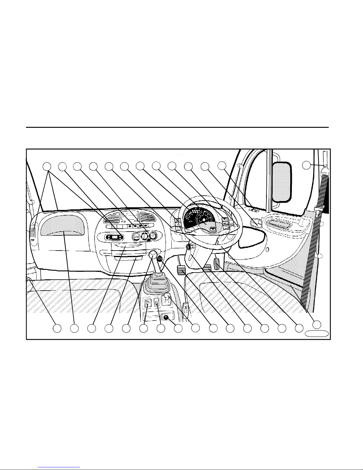
Interior
FN0015a
5
7
9
8
2 4
17
6
3
1 11
26 19 20 16 15 14 27 22 21 23 24
20
25
18
28
13
10
12
Page 5
D E S C R I P T I O N
5
1Combined lever switch
- turn signals
- side marker lights
- low beam
- high beam
2Combined lever switch
- wipers
- washers
- engine brake
3Controllers
- front fog lamps
- tail fog lamps
- display of AdBlue Level
4Controllers
- emergency flasher
- rear-view mirrors heating
5Controllers
- power-take-off drive (PTO)
*
- differential lock
- superstructure lighting
*
- air-conditioning
*
- cruise control
- cruise control - off / on
- cruise control - set / resume
6Measuring instruments and indicator lamps
7Digital clock
*
8Heater control
9Adjustable heater vents
10Window lift mechanism
*
11Door opening and locking
12Ignition switch
13Parking brake
14Headlamps beam adjustment
15Main rear-view mirrors
remote control
*
16Gearshift lever
17Horn
18Loudspeaker
19Ashtray
20Storage compartments
21Steering wheel positioning lever
22Clutch pedal
23Service brake pedal
24Accelerator pedal
25Seat belts height adjustment
*
26Storage box (c/w cover*),
fuse box
27Cigarette lighter
2812 V socket
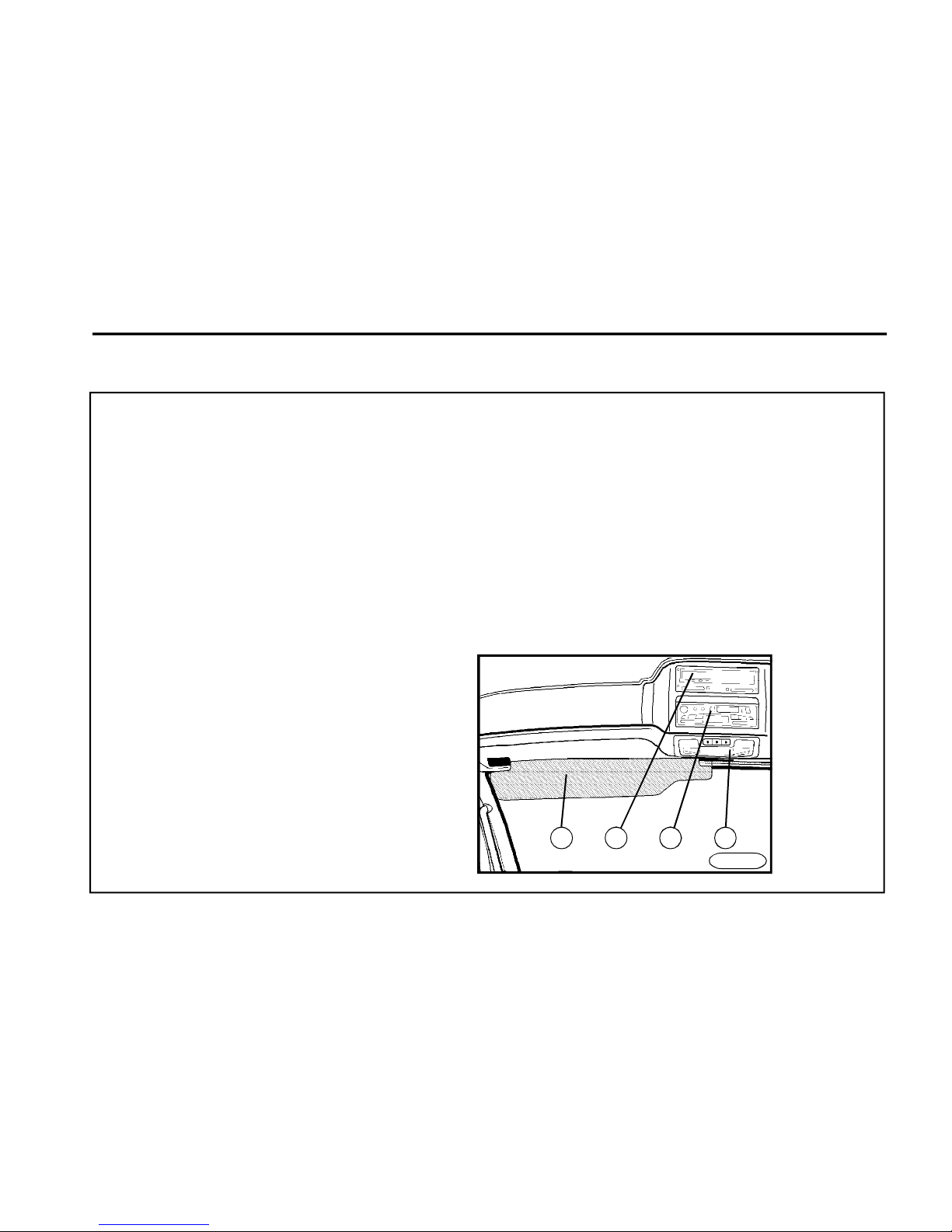
29Sun visor
30Digital tachograph
*
31Auto radio
*
32Dome light
29 30 3231
FN0011
Page 6
D E S C R I P T I O N
6
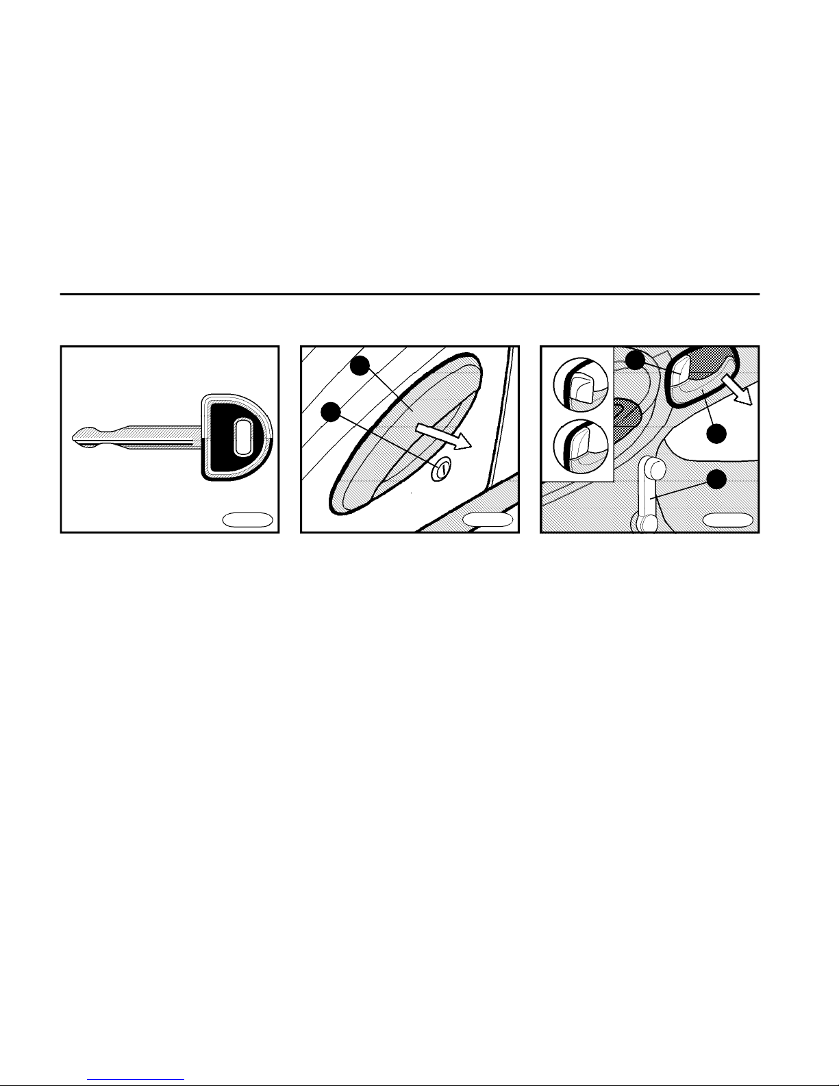
Doors
2
1
4
3
5
B
A
FN0030
Keys
FN0040FN0020
From outside
Both doors can be unlocked and locked
from outside by the key which you insert
and turn in the lock (item 1). Grasp the
handle grip (item 2) and pull it toward
you to open the door.
Unlocking - insert the key, give it 90°
turn towards the face of the vehicle and
back into the initial position when you
can remove it.
Locking - insert the key, gently turn it
towards the rear of the vehicle and back
into the initial position.
From inside
n (item 4)
A - door unlocked
B - door locked (when the door is locked
in that manner, it cannot be opened
neither from the outside, nor from the
inside).
n Pull the lever (item 3) to open the
door.
n Turn the handle (item 5) to open or to
shut the window.
n Your vehicle is delivered with two
keys - you should keep one in a safe
place outside the vehicle as a spare
one.
n Keys are provided with a label, on
which the key number is stamped. You
should keep the label in a safe place
outside the vehicle and put down the
number somewhere.
n If the vehicle is fitted with the analogue tachograph, the key to open it is
delivered with the vehicle.
Page 7
D E S C R I P T I O N
7
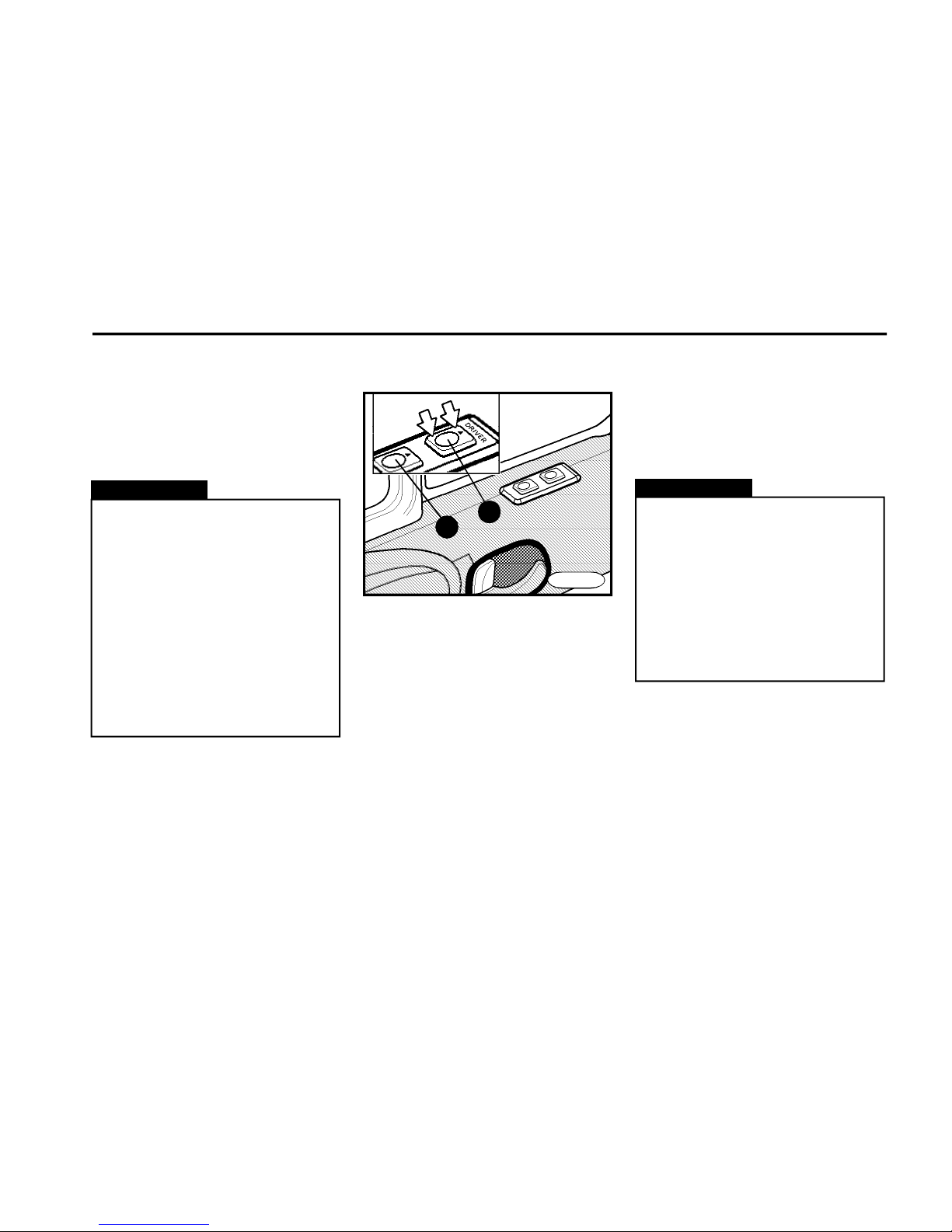
Electrically actuated windows
*
Central door locking*
Use the central door locking to lock or to
unlock both doors simultaneously from
the driver´s side.
n The windows can be lowered when
the ignition is in position "ON" only.
n The windows lowering is active only
when the button is hold depressed.
n The control buttons are situated on
the top of the door.
n Both side windows can be controlled from the driver´s place.
n Only the window on the RH side can
be controlled from the co-driver´s side.
n The control button (item 1) - for the
window on the driver´s side.
n The control button (item 2) - for the
window on the co-driver´s side.
2
1
Warning!
n Remember always to remove
the key from the ignition switch
before leaving the vehicle.
n Take care that the tailgate and
side door of the box body are locked properly. It is not allowed to
transport the loads which do not
allow a safe closing of the door.
Should the box body be damaged
due to the tailgate or side door
closed wrong, the manu-facturer
does not provide any guarantee for
it.
FN0050
Warning!
n Do not leave your fingers on the
window glass when closing it - the
mechanism can develop the force,
which may cause injury.
n The lowering button musn´t be
held pushed down if the door window is fully in its extreme stop
positions. If disregarded, the window lowering system can be damaged.
n Push the front part of the rocker
switch to open the windows, push the
other half of the rocker switch to shut
the windows.
Page 8
D E S C R I P T I O N
8
Instrument board - gauges
Indicator lights
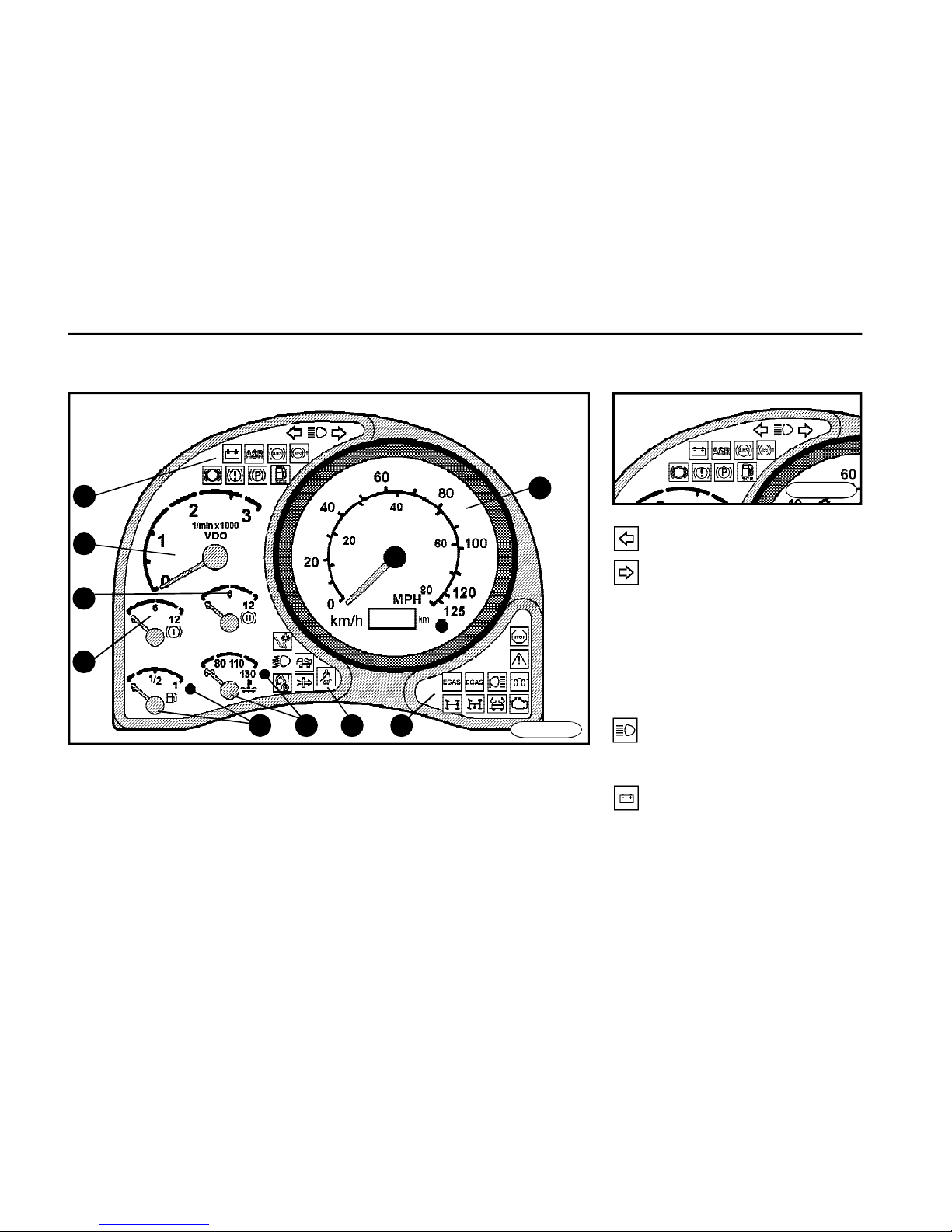
1 Tachometer
2 Engine speed - indicator
3 Air pressure gauge of 1st brake circuit
4 Air pressure gauge of 2nd brake circuit
5 Fuel gauge, indicator light
6 Coolant thermometer,
indicator light
7 Group of indicator lights I
8 Group of indicator lights II
9 Group of indicator lights III
Turn signals
n The left or the right indicator light
flashes when you operate the turn signal lever.
n A short interval of flashing indicates
a defective bulb in the turn signal light
(replace it immediately).
High beam
It lights with the high beam on.
Batteries charging
n It lights when the ignition is turned
"ON" and it must go out after starting
the engine.
5
8
6
1
7
2
4
3
FN0065N5
9
FN0065N4
Page 9

D E S C R I P T I O N
9
Parking brake
n It lights when the parking brake is
applied and at low air pressure in the
parking brake circuit.
n If it lights, do not move off or if it lights
up on the move, stop and proceed per
Chapter Troubleshooting.
n If it does not go out after starting or
it lights up during driving, move the
vehicle a safe distance off the road,
shut the engine off and proceed per
Chapter Troubleshooting.
ABS (vehicle)
ABS (trailer)
n It lights when the ignition is turned
"ON" (to check the function), it must go
out after a short while.
n If it does not go out after a short while
or lights up on the move, it is necessary
to stop and proceed per Chapter Trou-
bleshooting.
Brake system
malfunction
n It lights when the ignition is turned
"ON" (to check the function), after the
air brake system circuit is fully
pressured it must go out
n If it does not go out after a short while
or lights up on the move, it is necessary
to stop and proceed per Chapter Troubleshooting.
ASR*
n It glows whilst ASR is in operation
n Svítí při poruše systému ASR. Ne-
fukčnost systému ASR nemá vliv na
běžný provoz vozidla.
Wear of brake pads
n It lights when the brake pads wear
exceeds the max. allowable limit. Adapt
the driving speed and proceed per
Chapter Troubleshooting.
Signalisation of AdBlue
liquid level (reserve) in
the tank
n It lights when the AdBlue level in the
tank is low (cca 12l).
n Top up the AdBlue liquid at next diesel re-fuelling
n Simultaneously warning bulb lights
up „Engine - warning or engine
maintenance“.
Page 10
D E S C R I P T I O N
10
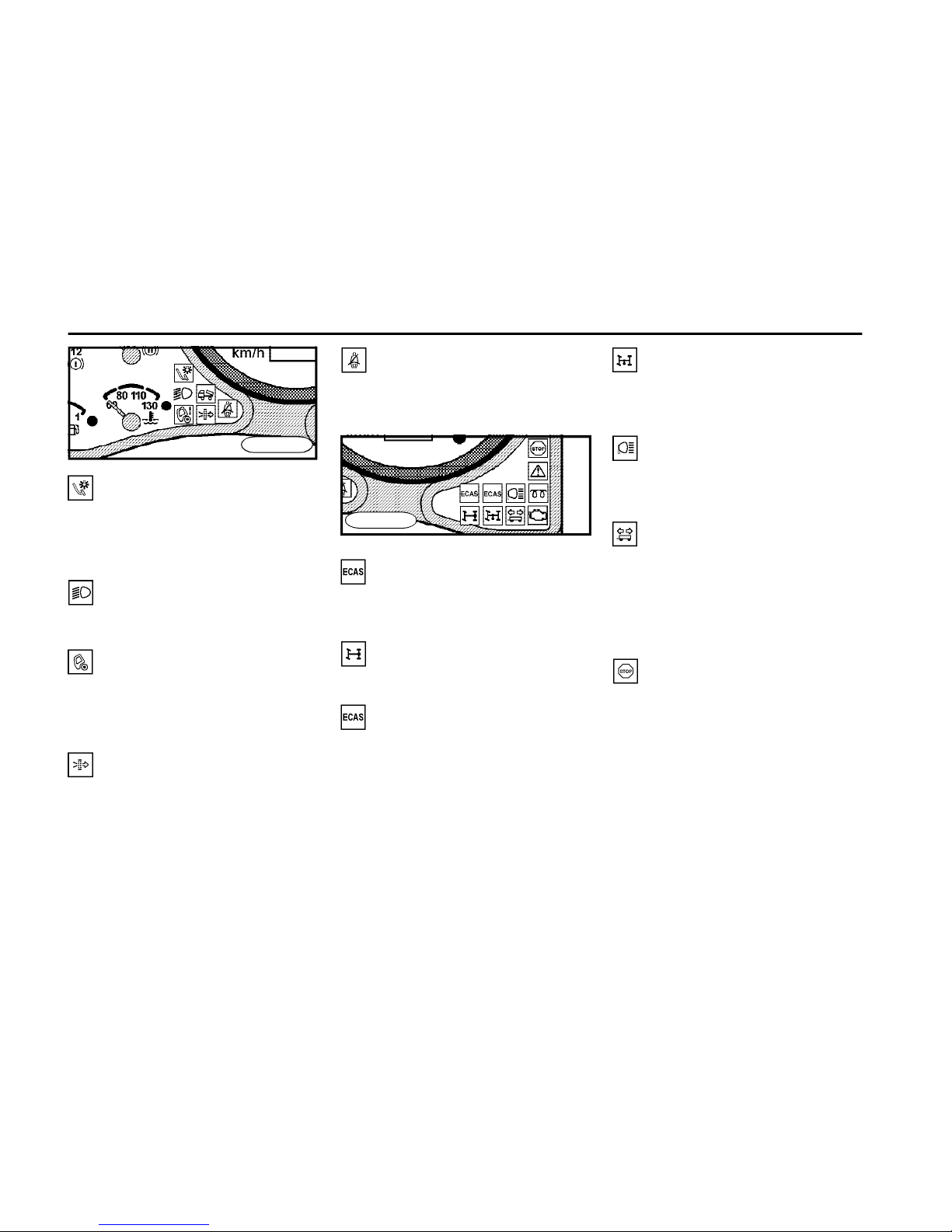
Seat belt*
It reminds you of not buckling by the
seat belt.
Differential lock
It lights when the differential lock is ON.
PTO*
Power - take off drive (PTO). It lights
when the PTO is on.
Reverse light
It lights when the reverse speed is
engaged.
Trailer turn signals*
n They light when the turn signals are
switched on and a trailer is coupled.
n A short flashing interval indicates a
faulty bulb in the turn signal light (replace the faulty bulb immediately).
Engine - stop
n It lights when the ignition is turned
"ON" (to check the function), it must go
out after a short while.
n It lights at a serious defect of the
engine.
n If it does not go out after a short while
or if it lights up on the move, move a safe
distance off the road, stop the engine and
proceed per Chapter Troubleshooting.
Stop light
n It comes on whilst brakes are being applied and a bulb of brake lights is defective.
n Replace the faulty bulb immediately.
Low beam
It lights with the low beam turned on.
Cabin tilting
It lights when the cabin does not rest
properly in its rear location (correct it
immediately).
Air filter (polluted)
n It lights when the filter cartridge has
been clogged.
n It is necessary to replace the filter
cartridge.
FN0065N5
FN0065N5
Pneumatic suspension*
/yellow control light/
Glowing if the tail part of the vehicle is
outside the driving position (level).
Failure in the pneumatic
suspension system* /red
warning light/
n Glowing if there is a system failure.
n If it desn´t go off after short time-out, or
it starts glowing while driving, the vehicle
must be halted and it must be proceeded
following the chapter Failures - repairs.
Page 11
D E S C R I P T I O N
11
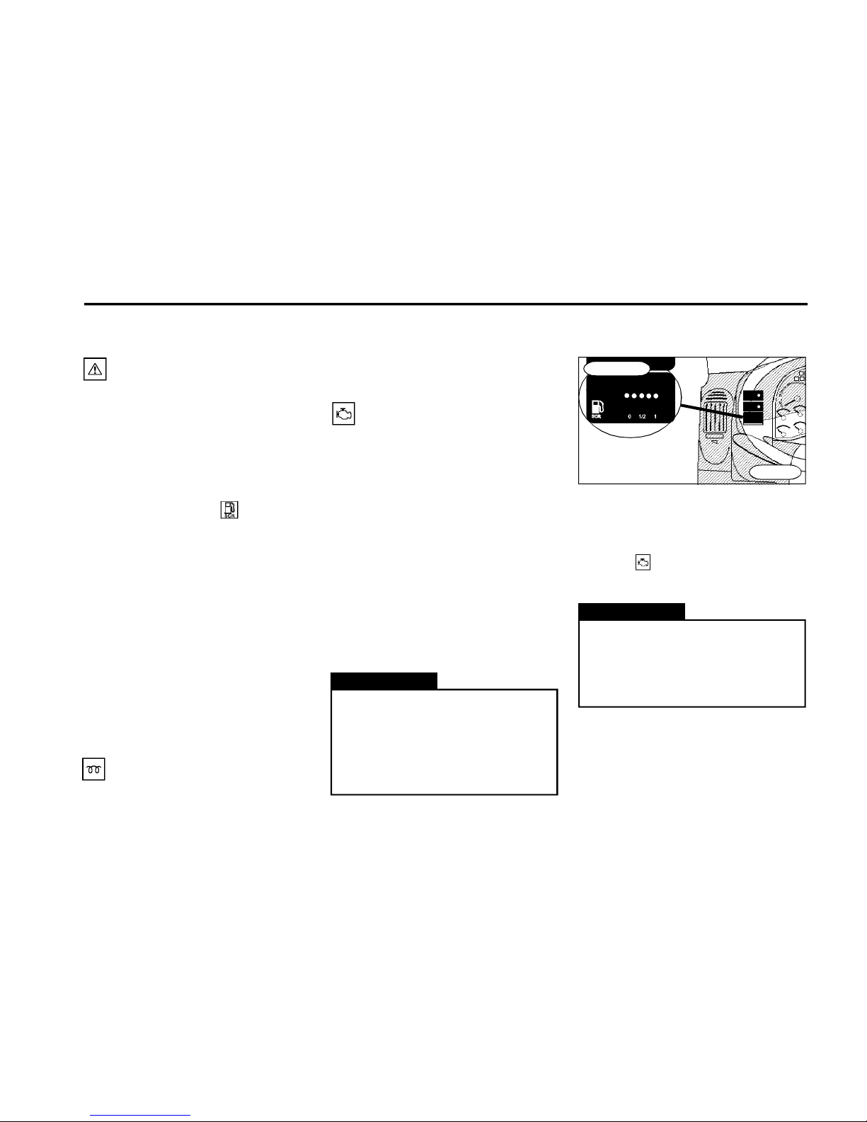
Glowing
It lights when the ignition is turned „ON“.
Engine - warning light
n It lights when the ignition is
turned "ON" (to check the function), it
must go out after a short while.
n It comes on when a malfunction or
defect on the engine component occurs
or “effective” level of fluid AdBlue is
lower than 12 litres. Simultaneously
warning bulb lights up „Signalisation of AdBlue liquid level (reserve) in
the tank.
n If it does not go out after a short while
or if it lights up on the move, move a safe
distance off the road, stop the engine
and proceed per Chapter Troublesho-
oting.
n If it flashes with the ignition in position "ON" for about 30 seconds, it is
necessary to proceed per Chapter Trou-
bleshooting.
n If it does not go out after a short while
or it flashes, proceed per Chapter Trou-
bleshooting.
Warning!
In order to prevent crystallization
of AdBlue on components of the
SCR system, a certain amount of
AdBlue remain in the tank – so
called unusable amount –
approx. 9 l.
SCR system malfunction
n It lights with the ignition in position
"ON" (to check the function),it must go
out after a short while.
n It lights when a fault or malfunction in
the SCR (Selective Catalytic Reduction) system occurs.
n If the warning light flashes, the fluid
AdBlue in the tank is lower than 10 l. It
is necessary to refill the AdBlue at the
nearest occasion.
n If it does not go out after a short while
or flashes even after topping up the
AdBlue fluid, it si necessary to proceed
per Chapter Troubleshooting.
You shall start the engine only after it
goes out.
Display of AdBlue Level
If the AdBlue tank is emptied, then
after the first engine stop the output of the engine is reduced for
next drives. This stage lasts until
the AdBlue tank is re-filled.
n Signals continuosly AdBlue level in
the tank.
n If the AdBlue tank is emptied, war-
ning light "SCR system malfuncti-
on" starts flashing.
Warning!
172_7287p3
FN0120
Page 12
D E S C R I P T I O N
12
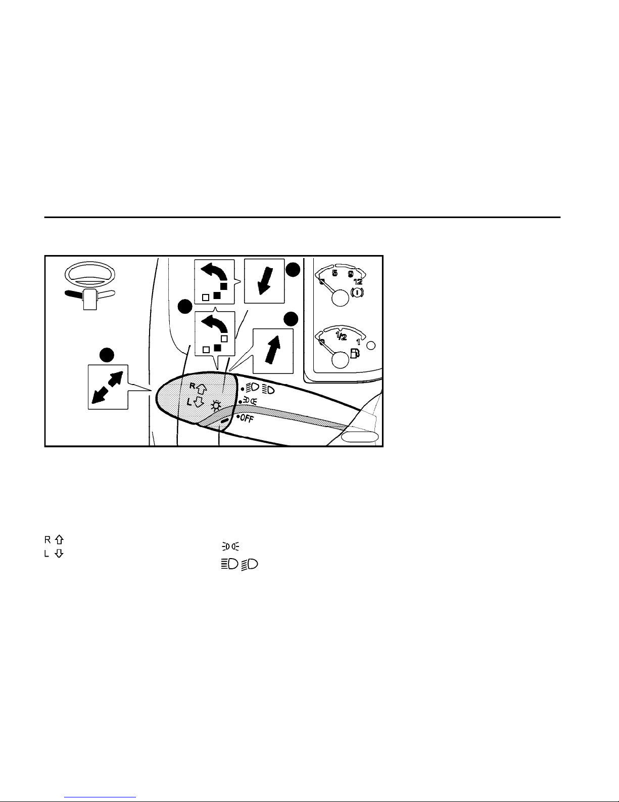
n The audible signalling is active when
the lights are on and the door is open.
3Low / high beam changing
n To turn on the high beam, push the
lever away from the steering wheel (the
indicator light will come on to indicate
the high beam function).
n Pull the lever to the initial position to
change over to the low beam.
4Headlight flasher
n Move the lever slightly toward the
steering wheel (the high beam indicator light will come on).
n Headlights are on until you release
the lever.
1Turn signals
Turn signals are active when the ignition is in the position "ON". Move the
lever perpedicularly towards the steering wheel axis to switch the turn signals on.
right turn signal - lever up
left turn signal - lever down
2
Side marker lights and low beam
Turn the rotary end of the lever to switch
them on.
The lights, whose symbol is against
the mark, are on:
OFF
lights off
side marker lights on
low beam (and/or high beam) on
Combined lever switch
3
2
1
4
FN0100
Page 13
D E S C R I P T I O N
13
FN0110
8
7
6
5
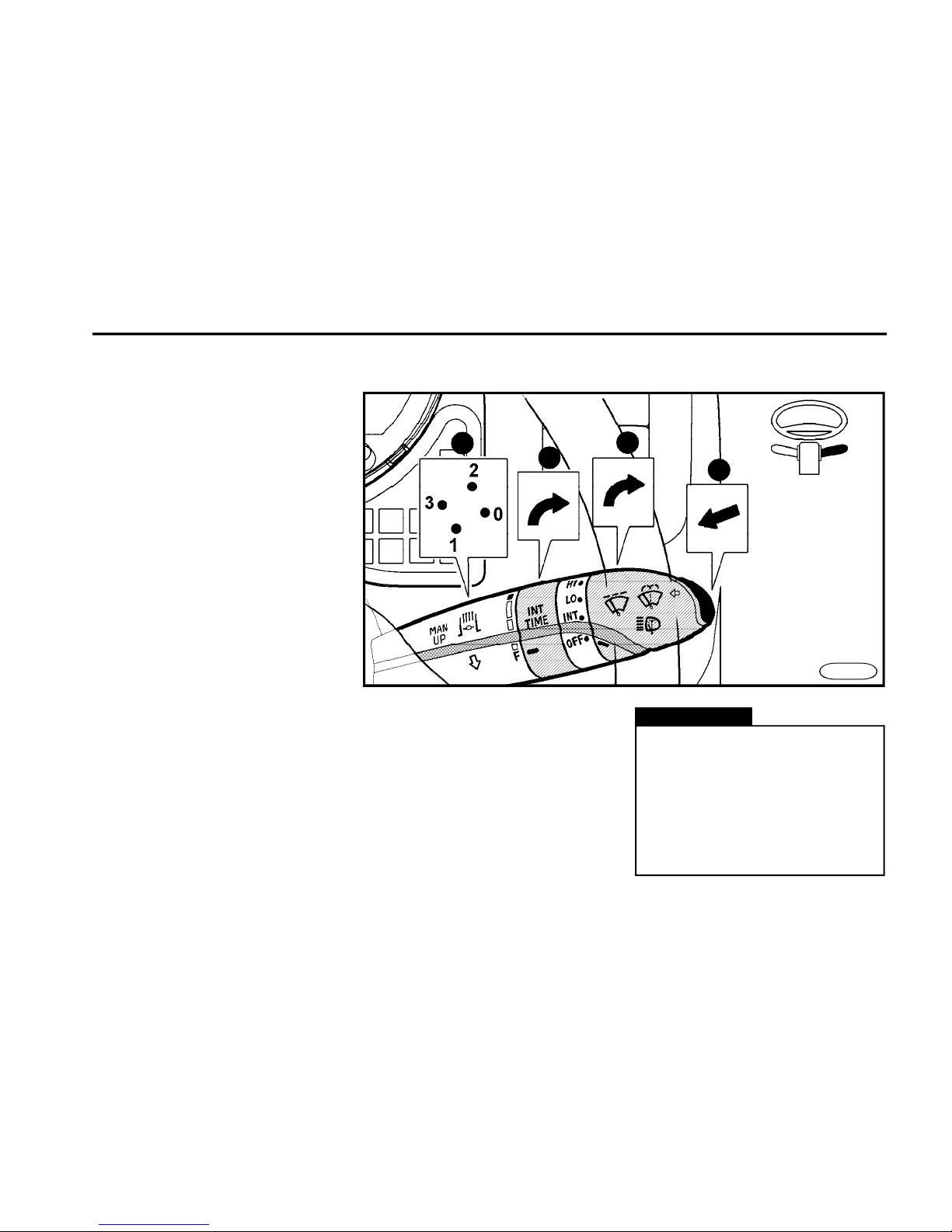
5Windshield washer
n Windshield wipers and washer are
active when the ignition is turned "ON".
n Push the switch at the end of the
control lever to turn on the washer. The
washer pump will operate until you
release the switch.
6Windshield wipers
Turn the rotary end of the lever to switch
the wipers on:
OFF wipers off
INT intermittent wiping (you can select
any wiping interval by the rotary
ring in steps - item 7)
LO low speed and continuous wiping
HI high speed and continuous wiping
7Intermittent wiping interval
control
The wiping interval is the shortest in the
position F, increase it by turning the
ring.
8Engine brake
Position 0 - move the controller away
from you and down - the engine brake
is off.
Position 1 - move the controller toward
Warning!
n For the sake of proper operation the engine brake has to be
switched on (switched off) at least
once a week. Its lifetime will be
prolonged by this measure.
n Depress the accelerator pedal
to put the engine brake automatically out of function.
you and down - the engine brake is activated when the service brake is applied.
Position 2 - move the controller away
from you and up - the engine brake
works when the accelerator pedal is
released (in the speed zone above the
idle run).
Position 3 - move the controller towards
you and up - combined function.
Page 14
D E S C R I P T I O N
14
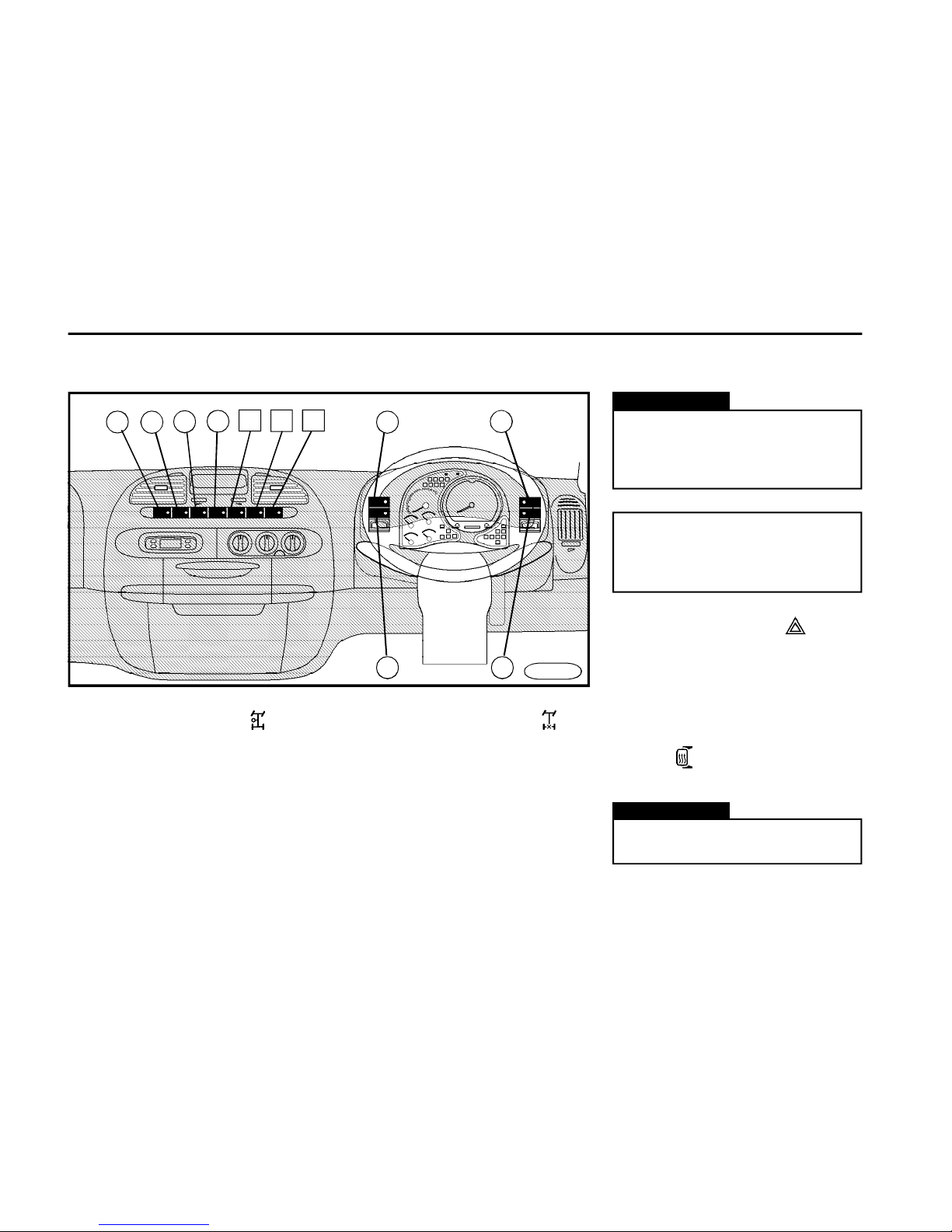
Controllers
1Power take-off drive
*
n It can be engaged on vehicle at
standstill and after the engine speed
drops - after about 6 s.
n When the engine is running, depress
the clutch pedal to engage the PTO.
n The indicator light comes on to
indicate the PTO engagement.
2 Differential lock on /off
n It can be engaged on vehicle at
standstill and after the engine speed
drops - after about 6 s.
n Use it only for the necessarily needed
time to overcome the hard driving
conditions.
n The indicator light comes on to
indicate the differential lock engagement.
Warning!
Positions 1 and 2 can be engaged
when the air pressure exceeds 0.55
MPa - otherwise the engagement
cannot be guaranteed.
Warning!
Operate the heating for the
necessarily required time only.
.
We recommend you to switch the
differential lock on / off once a
week at least - hereby the service
life will increase
FN0125
3
1
2
8
5
6
4
7
11109
3Emergency flasher
n The bulb in the switch indicates the
function.
n It can be turned on even with the
ignition off.
4Main rear-view mirrors
heating
*
n It is indicated by the bulb in the switch.
Page 15
D E S C R I P T I O N
15
9Resume / reduce
n It resumes the speed already set on
the cruise control.
This can also reduce the engine speed
during driving or in the PTO regime.
10Permanent (main)
n It activates the cruise control or PTO
regime speed setting.
11Adjust / increase
n It stores the instantaneous speed
of the cruise control.
This control switch can also increase
the engine speed during driving or in
the PTO regime.
n When the diagnostic test is
performed, another malfunction code
will enter when pushed.
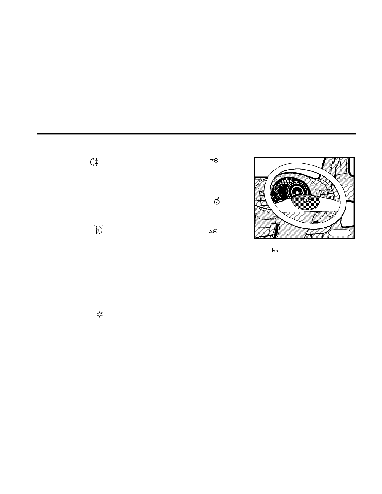
Horn
The horn switch is situated in the middle
of the steering wheel.
5Tail fog lamps
n The tail fog lamps can be turned on
only when the low beam or front fog
lamps are on.
n With regard to a dazzling effect, it can
be turned on only in fog, heavy rain or
snow.
n The bulb in the switch comes on to
indicate the function.
6Fog headlights
n Fog headlights can be turned on
when the side marker lights and low
beam and/or high beam are on.
n The bulb in the switch comes on to
indicate the function.
7Loading space lighting*
The bulb in the switch comes on to
indicate the function.
8Air-conditioning *
n The cooling equipment works with
the engine running only.
n The air-conditioning does not work
when the rotary switch of the fan is off.
n The bulb in the switch indicates its
function.
FN0135
Page 16
D E S C R I P T I O N
16
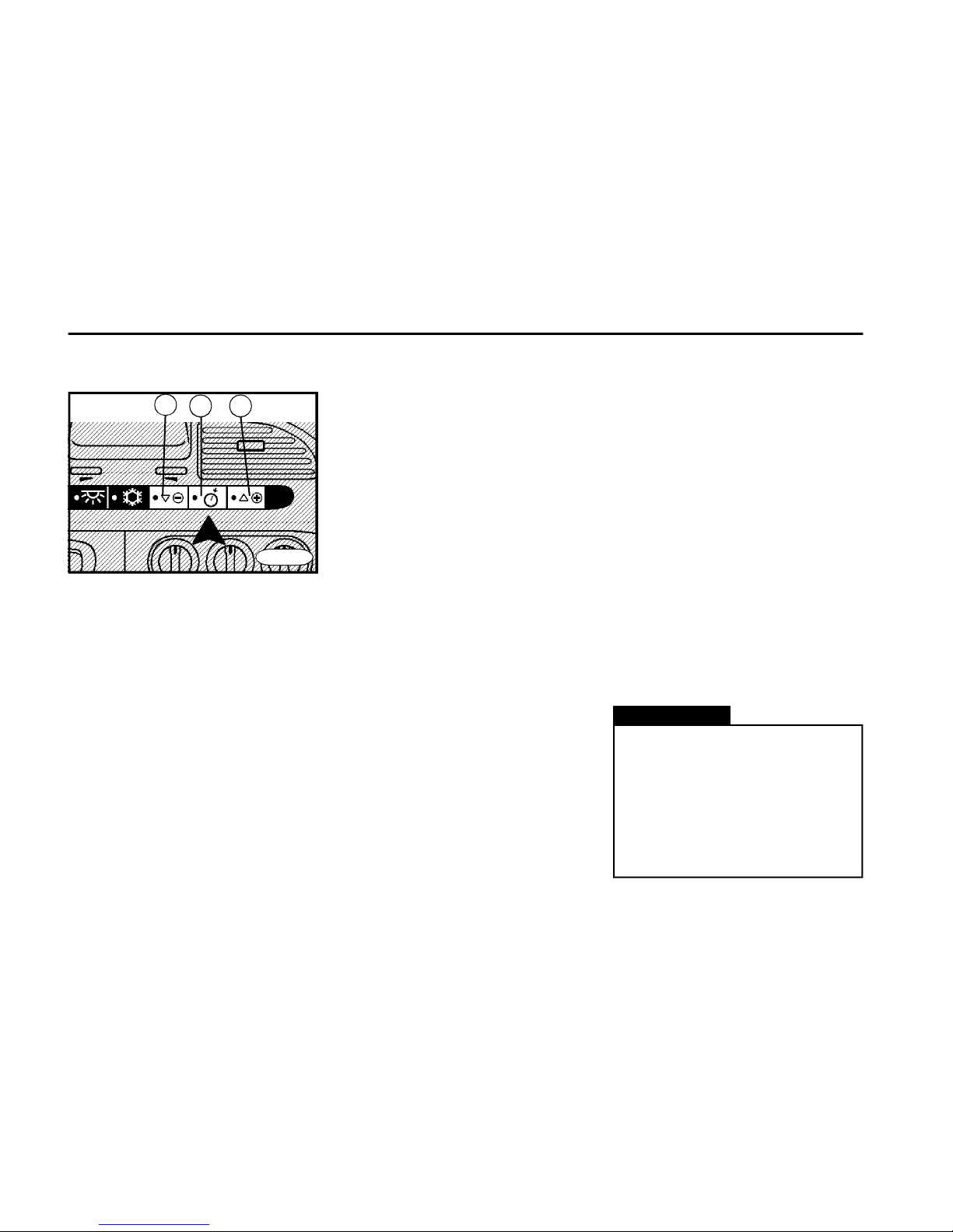
Cruise control
Warning!
n When the cruise control is not
used, the "permanent (main)" control
button 10 must be switched off.
n The vehicle speed can be
influenced by driving uphill or by the
load weight. For that reason use the
cruise control only when driving on
level ground or in slight hilly terrain.
Setting the PTO speed on
vehicle at standstill
n Push the button 10 to activate the PTO.
n Push and hold the button 11 "adjust/
increase" depressed (the adjustable speed
range 850 ÷ 2,500 rpm) to increase the speed
- hold the button depressed to increase the
PTO speed gradually - when the button is
depressed repeatedly, the PTO speed
increases by about 25 rpm steps.
n Push the button 9 "resume / reduce" to
activate the speed 1,200 rpm automatically.
n By pressing the button 11 “adjust/
increase” 850 rpm will be automatically set.
n Other rpm values may be set upon
special request by the manufacturer.
Adjustment of cruise control
n Push the button 10 to activate the
cruise control.
n When the desired speed has been
achieved, push briefly the button 11
"adjust / increase" - now the speed is
stored and maintained by the engine
without applying the accelerator pedal.
n The speed can be increased by
depressing the accelerator pedal - after
releasing it, the cruise control function
is resumed (however, first the cruise
control must be activated).
n All functions will be cancelled by
depressing the clutch or brake pedal
and/or by switching off the button 10.
The resuming of the cruise control
function can be performed when you
push briefly the button 9 "resume /
reduce", it means that the cruise control
need not be set again.
n If the exhaust brake’s stalk is in the
position 1,2 or 3 and if vehicle speed
exceeds the set-up speed about approx. 3 km/h (riding downhill) the exhaust brake is automatically applied.
When the desired speed is reached the
exhaust brake will come out.
n The cruise control allows you to
maintain a desired speed (engine speed
- both on the move and in the PTO
regime) - without actuating the
accelerator pedal.
n Use three control buttons located on
the central panel of the instrument board
to control it.
n The cruise control starts to operate
when the speed reaches about 48 km/h
and in the PTO regime up to 48 km/h (it
can be selected).
FN0136
1110
9
Page 17
D E S C R I P T I O N
17
2
FN0133a
Diagnostic sockets
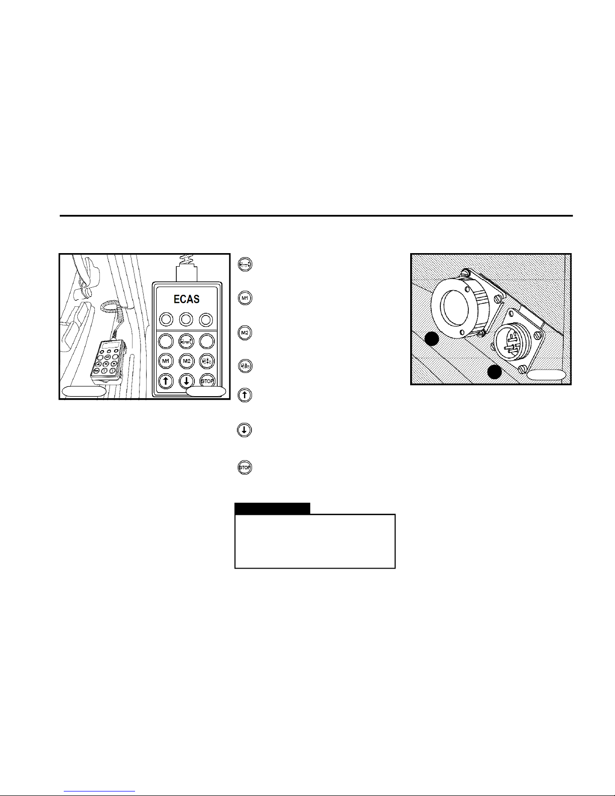
n Diagnostic sockets are situated
under the storage box in the instrument
board.
n They are accessible after removal of
the storage box bottom, which is released by turning the two rotary holders
(sense of rotation is shown on the cover).
1 Socket for the ABS,
ECAS diagnostics
2 Socket for the engine
diagnostics
Vehicle height adjustment by remote control*
n Operated by remote control device,
placed in the holder on the rear wall of
the cab, in extended cab versions at the
driver´s seat.
FN0134_b
System "switch-on" - indicated
by control lamp on the remote
control device
Memory 1 - memory input, move
to saved position
Memory 2 - memory input, move
to saved position
Automatic adjustment to normal
(operational) driving height.
Move "Upwards"
Move "Downwards"
STOP - the operation - raising or
lowering the pneumatic suspension - is immediately halted..
DCS00054
n Operating and more detailed instructions for handling the pneumatic suspension can be found in
the chapter "Operating guidelines"
Warning!
1
Page 18
D E S C R I P T I O N
18
Ignition switch and steering lock
Switch positions
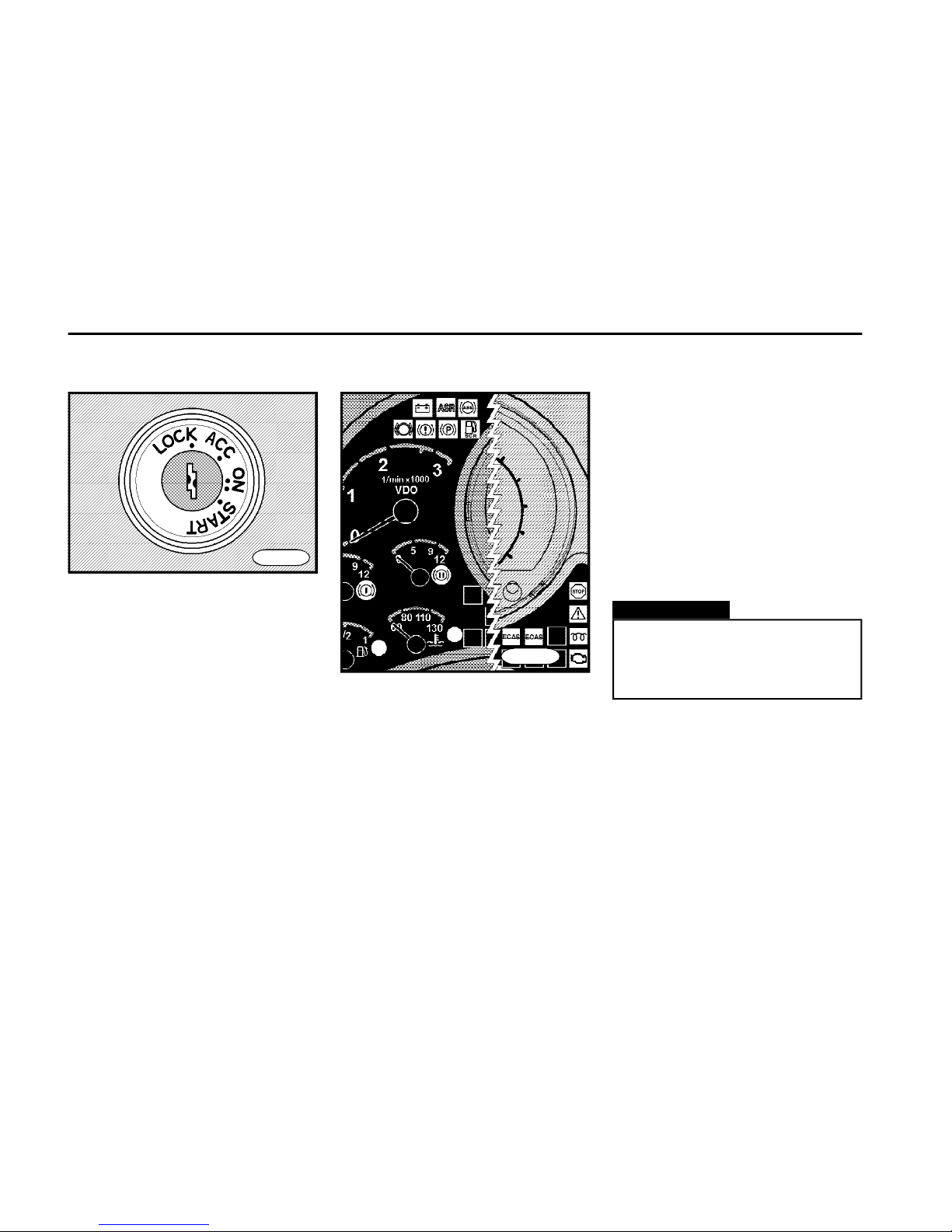
n "LOCK" position
Only in this position the key can be
inserted and removed. Only tachograph, electric clock or radio are powered.
The steering shaft will be automatically
locked in this position.
n "ACC" position
Steering is unlocked, electric circuits
connected through the ignition switch
are not powered. When turning the ignition from "ON" into this position, the
engine will be stopped.
FN0140
Warning!
If after a moment any indicator
light, at which its own test was
activated, remains on, proceed per
Chapter "Troubleshooting".
n Position "ON"
The indicator lights (see Fig.) of battery
charging, brake system malfunction,
parking brake, ASR function, glowing,
ABS, coolant temperature and reserve
fuel amount, engine - stop, engine warning, engine - maintenance, SCR
and ECAS system malfunction will come
on. After several seconds only the indicator lights of battery charging, parking
brake and/or glowing and the operation
fluids levels dependent, also the indicator lights of the fuel minimum level and
the AdBlue fluid minimum level remain
on. If the air pressure in the brake system is insufficient, the indicator light of
the brake system malfunction remains
ON. When the parking brake is applied
its warning lamp will stay on. When the
glowing light goes out, the engine is
ready to be started. Electric circuits connected via ignition switch are powered.
FN015cu1
Page 19
D E S C R I P T I O N
19
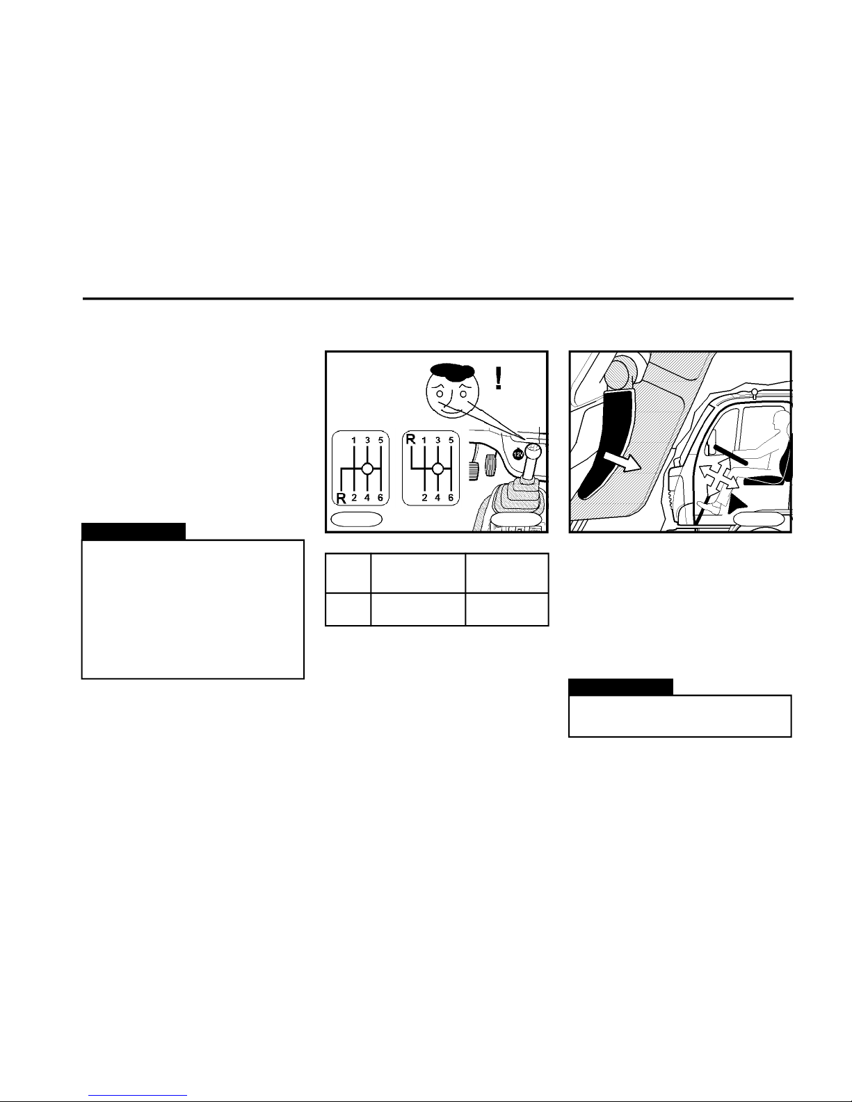
n Pull the positioning lever towards
you to release the steering wheel and
adjust the steering wheel into the
desired position.
n After the desired steering wheel
position has been achieved, push the
positioning lever as far as it goes.
Warning!
It is not permitted to adjust the
steering wheel during driving.
FN0170
Steering wheel adjustment
Warning!
n The ignition switch function is
secured with the battery circuit
breaker on.
n Do not switch off the battery
circuit breaker or do not disconnect battery clamps to avoid damage to alternator or some electric consumers.
n "START" position
The engine can be started only when no
gear speed is shifted.
Do not depress the accelerator pedal
while starting.
The position is not arrested. When
starting repeatedly, move the key back
to position "ACC" - this prevents to start
the already running engine and avoids
damage to starter.
Gearshift lever
Type of Number of
gearbox gear speeds
ZF 6 S 850 6
Engage gear speeds mechanically by
the gearshift lever with the clutch pedal
depressed.
FN0160
FN0161
Page 20
D E S C R I P T I O N
20
Heating and ventilation
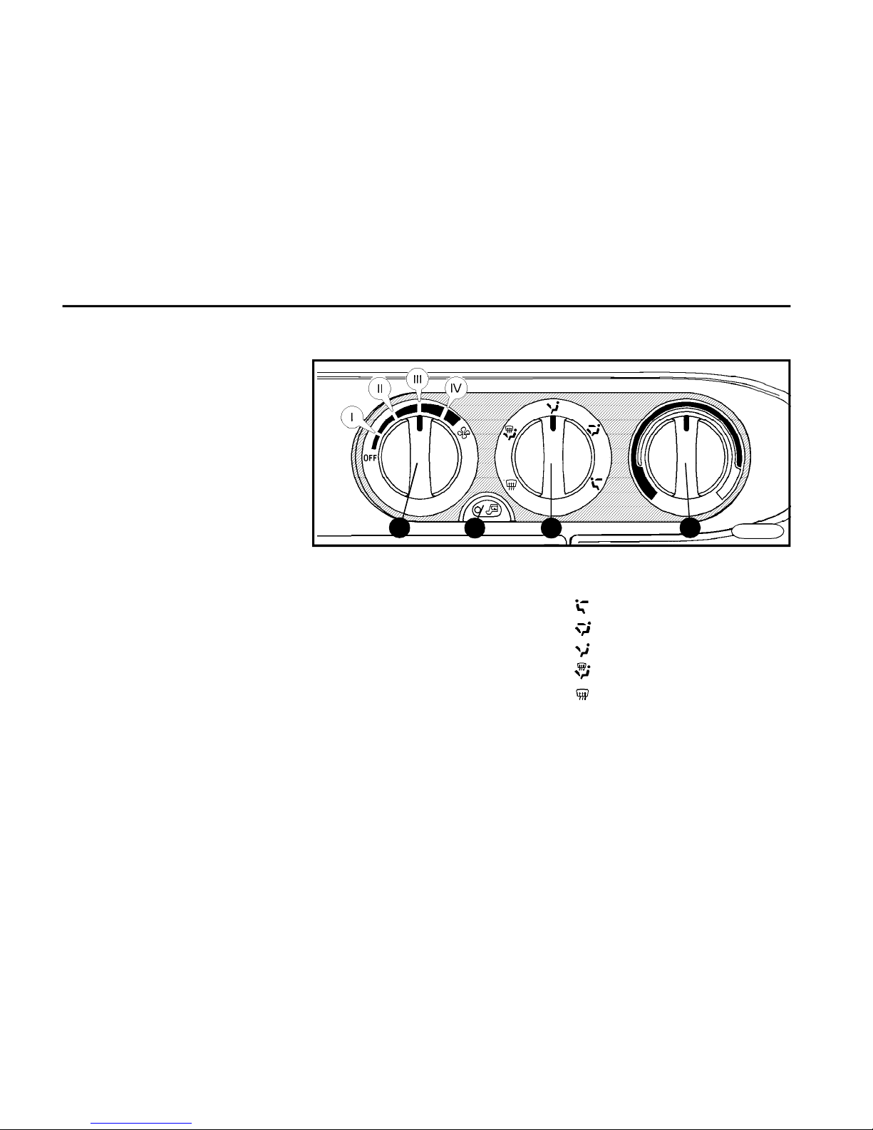
1Heater fan control
2Airflow direction control
3Heater valve control knob - regulation
of temperature of the airflow
4Regime of air circulation
n The cabin is heated by the hot-water
heating. It can be used also for heating
of coolant in the cooling and heating
circuits after starting the engine.
n The heater is controlled by heater
control elements on the instrument
board.
n By turning the heating control knob
(item 3) you will regulate volume of cold
and hot air flowing into the cab(turn the
control knob to the red zone to supply
the hot air).
n Use the control knob (item 1) to adjust the fan speed and thus the air
volume circulating through the system.
The airflow speed can be set in four
steps.
n The control knob of the airflow
direction (item 2) allows you to change
the direction of airflow (way of cabin
heating).
n Push the button (item 4) to turn on /
off the regime of circulating air in the
cabin.
to crew heads
to crew feet and heads
to crew feet
to feet , windshield and side windows
to windshield and side windows
n Deflect the fins (item 5) at air vents to
change the angle of airflow.
The air volume emitted from individual
vents is controlled by thumbwheels
(item 6).
31
24
FN0185
Page 21
D E S C R I P T I O N
21
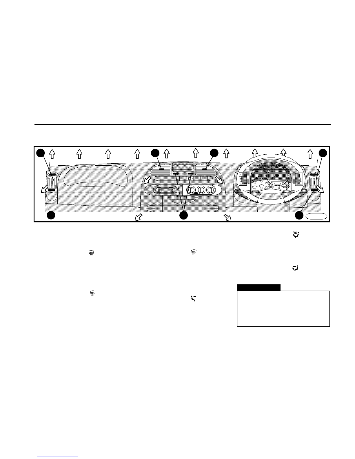
Window defogging
n (item 1) fully to position IV
n (item 3) to extreme left
n (item 2) to position
n Close air vents by thumbwheels.
Windshield defrosting
n (item 1) fully to position IV
n (item 3) to extreme left
n (item 2) to position
n Switch on the regime of air circulation
n Close air vents by thumbwheels.
Keeping windows being not
fogged under increased humidity
When windows are still being fogged
(for example in rainy weather), it is necessary:
n (item 1) to position II or III.
n (item 2) to position
n (item 3) if necessary, turn on hea-
ting.
Ventilation
n (item 1) to desired position.
n (item 3) to extreme right.
n (item 2) to position
(or to desired position).
Optimum heating
n (item 1) to position II or III.
n (item 3) to desired heating output.
n (item 2) to position
Maximum heating
n (item 1) to position IV.
n (item 3) to extreme left
n (item 2) to position
n Switch on the regime of air circulation.
Warning!
The heating output depends on the
coolant temperature. The maximum heating output can be obtained after the engine has reached
the opera-ting temperature.
5
5
5
66
6
5
FN0195
Page 22
D E S C R I P T I O N
22
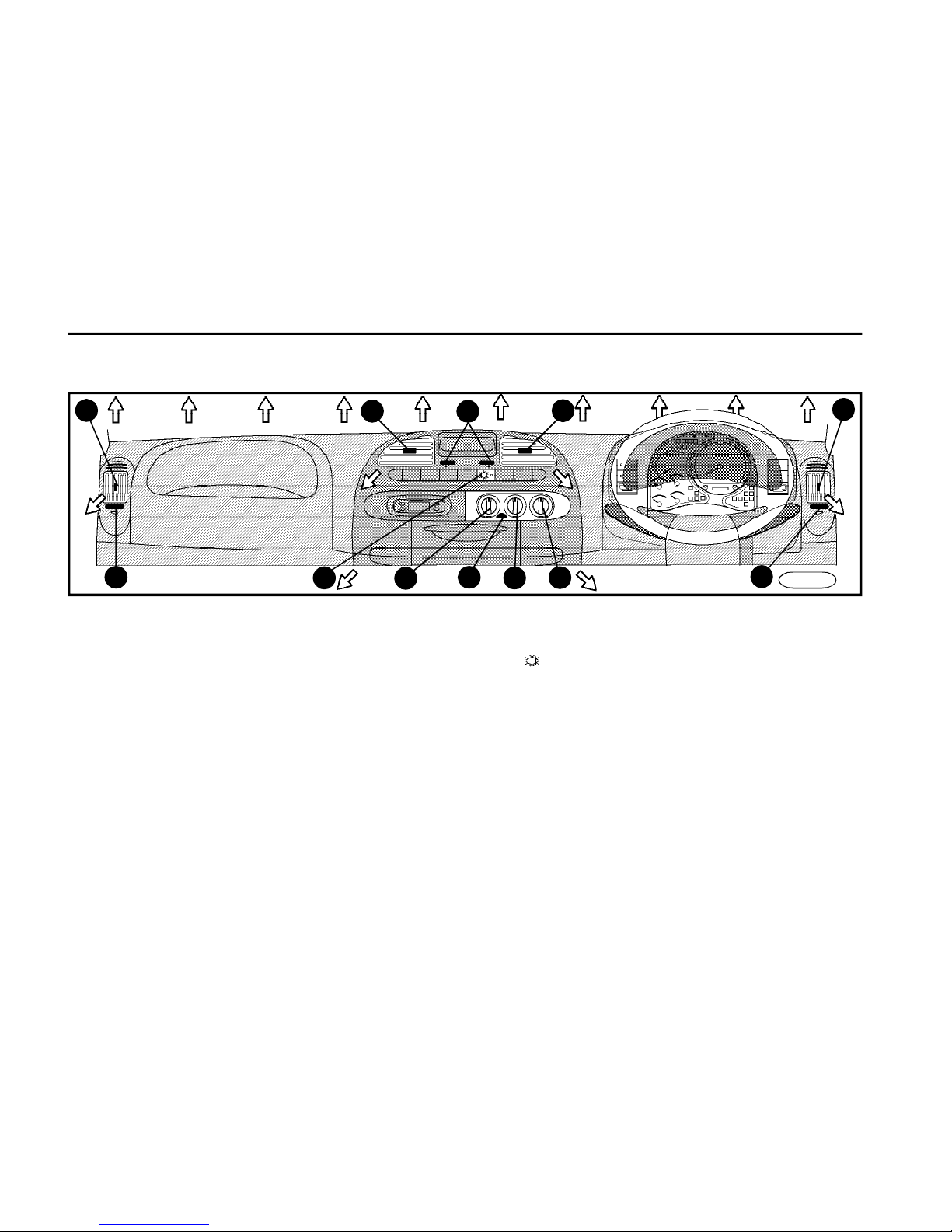
Air-conditioning
*
n The air-conditioning is a combined
cooling and heating device.
n The a/c cooling unit cools down the
air and dehumidifies it.
n The cooling unit works with the engine running only.
n Use the control knob (item 2) to control the fan speed and thus also the air
volume circulating through the system.
Adjust the air volume by selecting one
of four fan speeds.
n The airflow direction control knob
(item 2) allows to change the airflow
direction (way of cabin heating).
n Push the button (item 5) to switch on/
off the regime of circulating air in cabin
(signalled by the bulb in the button).
n Deflect the fins (item 6) at air vents to
adjust the airflow in desired angle. The
air volume is controlled by thumbwheels (item 7).
Control elements
n Switch on/off the air-conditioning by
means of the switch (item 1) (signalled by the bulb in the switch).
n The air-conditioning does not work if
the fan rotary switch is off.
n Depending on the heater valve control knob position (item 4), the temperature of the drawn airflow is controlled
(when in the red zone, the hot air is
circulated and contrariwise). It can be
used even with the air-conditioning on.
2
3
4
5
6
7
6 7
6
6
7
FN0195
2
Page 23
D E S C R I P T I O N
23
Warning!
Smoking is not advisable when
being in regime of air circulation.
Warning!
n When the vehicle was parked in
the direct sun, remember to open
the windows before switching on
the air-conditioning.
n It is recommended to switch on
the air-conditioning once a week
at least (even in the winter months) to prolong the a/c service life.
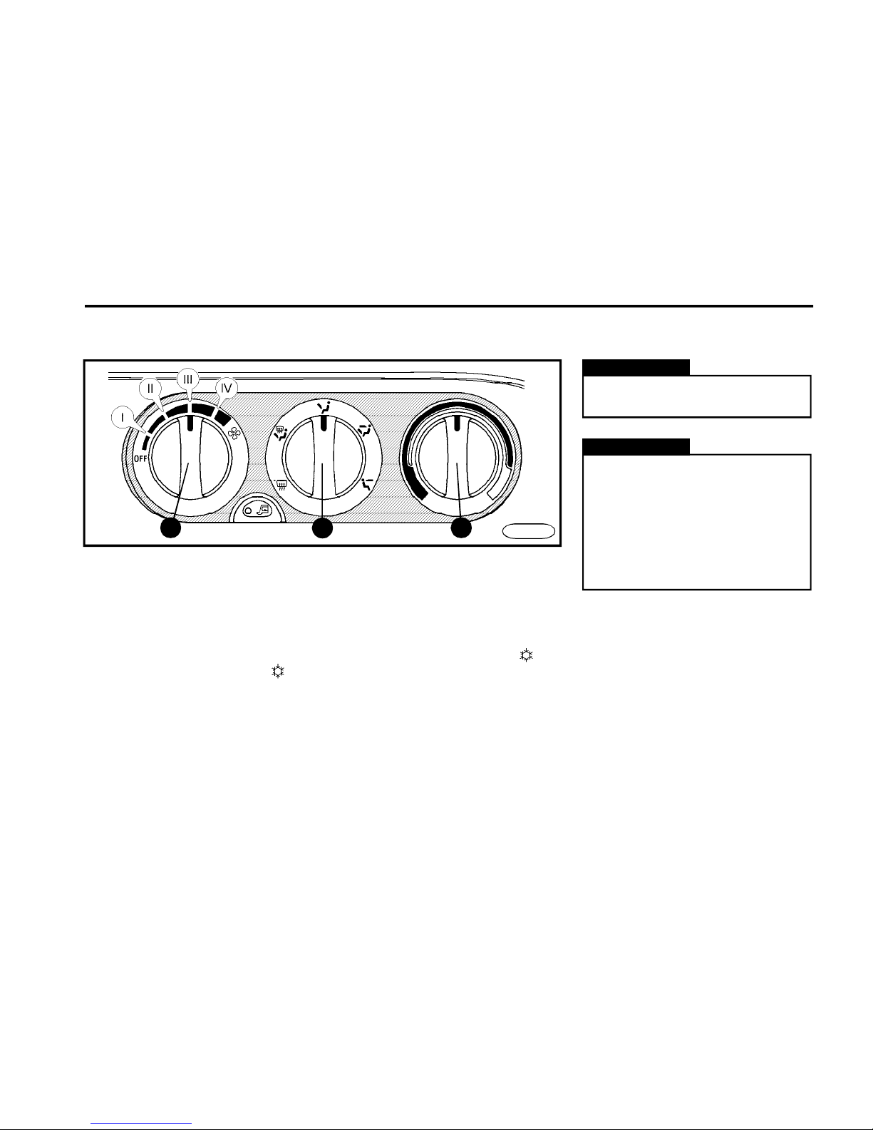
Optimum cooling
n (item 1) to desired position (position
II or III are optimum)
n (item 3) to extreme right, turn it slightly
to left to adjust the temperature if needed
n (item 2) move it to position
n Push the button with symbol (the
bulb comes on in the switch)
n The outside air is being sucked up
and cooled in that regime
Maximum cooling
n Close all windows
n (item 1) to position IV
n (item 3) to extreme right
n (item 2) turn it to position
n Push the button with symbol (the
bulb comes on in the switch)
n Switch on the regime of air circulation
31
2
FN0185
Page 24
D E S C R I P T I O N
24
2
3
4
1
Seats
1
2
FN0200
Warning!
For reasons of safety the driver´s
seat may be adjusted on vehicle at
standstill only.
n The seat should be adjusted so that
the driver could control the pedals safely.
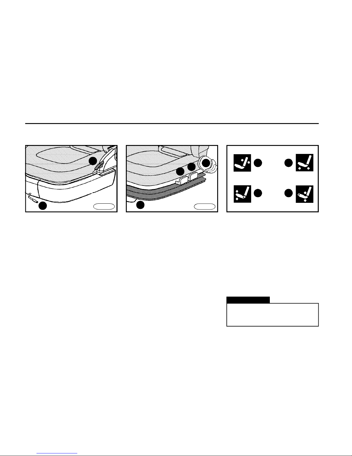
Seat cushion inclination (c)
and height (d) adjustment on
the pneumatically controlled
driver´s seat
*
n Raise the lever (item 3) to adjust the
front part of the seat cushion.
n Raise the lever (item 4) to adjust the
rear part of the seat cushion.
n Take your body weight off to adjust
the seat cushion height.
Correct adjustment of seats
n The seatback should be adjusted
so that the driver can hold the steering
wheel at its top point with hands slightly
bent.
n A quick and safe handling the controls required for the drive must be
secured.
n Keeping your body at ease for the
maximum protection offered by seat
belts must be obtained.
FN0210
Seatback adjustment (a)
Lift the control lever (item 1) with your
body weight taken on the seatback to tilt
the seatback to the rear. To adjust the
seatback to the front, lift the control lever
with your body weight taken on the seatback slightly and after that release the
seatback, which will tilt automa-tically
forward. Release the lever to lock the
seatback in position.
Forward and backward
adjustment (b)
n Pull the control lever (item 2) up to
release the longitudinal shift and the
seat can be adjusted into desired position. Release the lever to lock the seat.
a b
c d
Fixed seat
Sprung seat
Page 25
D E S C R I P T I O N
25
Warning!
n The head restraint being set
properly will support the back of
the skull when the vehicle is
crashed from the rear.
n For reasons of safety the head
restraint may be adjusted on
vehicle at standstill only.
FN0220
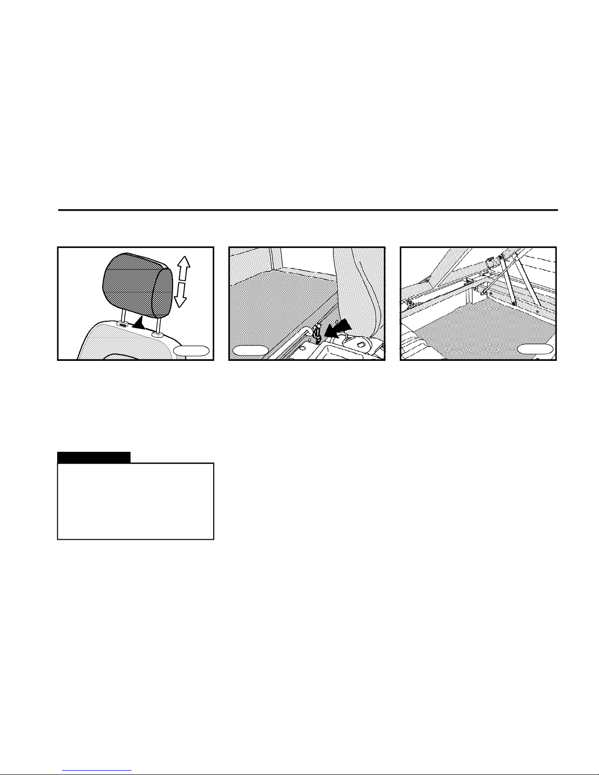
n Head restraints are height adjustable.
n
To adjust the head restraint vertically,
push the stop toward the rear cab wall.
n Adjust the head restraint so that its
position is adapted to fit the seating
height of occupant.
Head restraints Sleep couch
On vehicle versions with a long cab, there
is an emergency couch with a storage
compartment in the rear part of the cab.
The storage compartment is accessible after unlocking the rubber element
and tilting the couch.
FN0221
FN0222
Page 26
D E S C R I P T I O N
26
Seat belts
FN0230
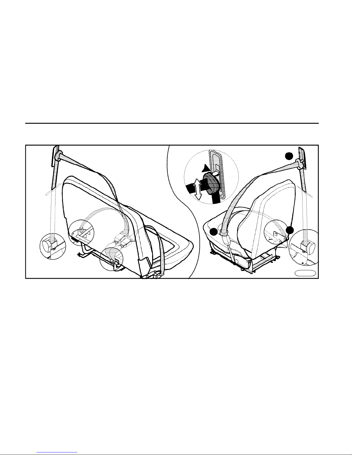
n The cabin is equipped with threepoint seat belts and retractors on two
side seats.
n The middle seat has got the twopoint seat belt and mechanical
adjusting equipment.
n Seat belts offer a protection for
passengers in case of an accident.
n Seat belts have to be buckled whenever
you drive the vehicle - even in urban driving.
Page 27

D E S C R I P T I O N
27
n The belt strap must not be worn
over rigid or breakable objects,
which are stored in your clothing in
pockets.
n Seat belts, which have been
subject to an accident or have
been damaged, must be unconditionally replaced with new ones.
n Take care that the belt is not
twisted and is worn across pelvis
and not across soft parts of the
body if possible.
n The maximum effect can be
reached only with a correct
seating position in cabin.
n Do not strap in more than one
person with each belt.
n Keep the seat belts clean (dirt
impairs the function of the
retractor). Use the soap water to
clean the seat belts.
n If the seat belt has been damaged, it is necessary to have it
replaced.
Warning!
Use of seat belts
n The respective warning light reminds
you of necessity of the use of seat belts *.
n Grasp the belt holding it at tongue
and slowly fit it across the chest and
pelvis.
n The belt must fit snugly to the centre
of arm and to your pelvis.
n If the belt locks when being pulled
out, release it, let it rewind and after that
pull it out again.
n Insert the belt tongue into a
respective seat buckle. The belt is
anchored properly when it clicks into a
buckle.
n To release the seat belt, press the
red marked cap on the buckle.
Seat belts height adjustment
*
n Due to the height adjustable belt
anchorage, the belt can be adapted to
fit the body dimensions.
n To adjust the belt height, push the
button downwards, tilt the upper
anchorage toward you (up) and adjust
it to the desired position.
Page 28
D E S C R I P T I O N
28
Rear-view mirrors
n Vehicles are equipped with heated
main rear-view mirrors.
n The heating is controlled by the controller on the instrument board and is
indicated by the indicator light situated
directly in the controller.
n Use the heating for the necessary
time only.
Rear-view mirrors
remote control
*
Warning!
n For reasons of safety the mirrors
must be adjusted prior to move off.
n Pay extreme attention when
considering the size and distances
of cars and other objects when
seen in a convex mirror. Always
remember that they will look
smaller and appear farther away
than in reality.
A
B
FN0240a
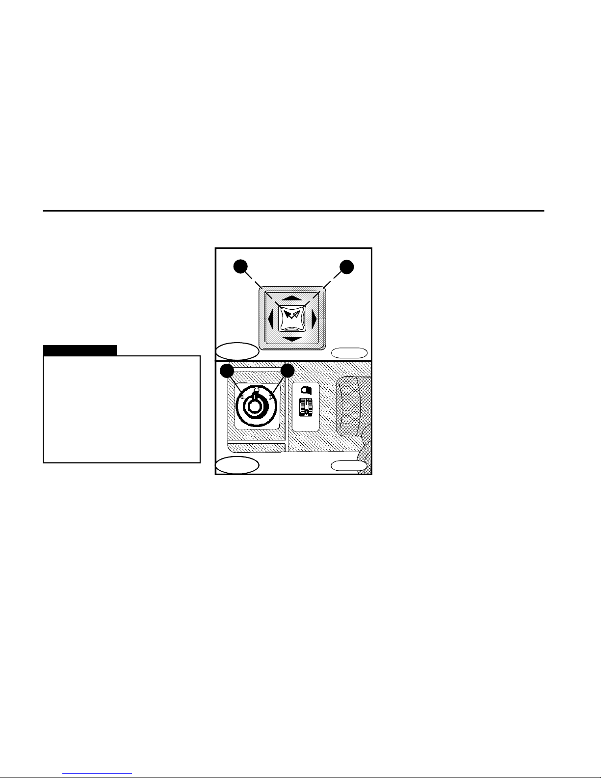
n Turn the controller to select adjustment of the left or right mirror.
to left - left mirror - position A
to right - right mirror - position B
n Deflect the four-position controller
to obtain the desired position of the
mirror.
FN0240
B
A
Version A
Version B
Page 29
D E S C R I P T I O N
29
Cabin interior lighting
Vehicle load
out of the max. payload
30% 50% 70% 100%
K 1 2 3
N 1 2 3
L 1 2
E 1 2
S 1 2
G 1 2
Headlights levelling device
FN0250a
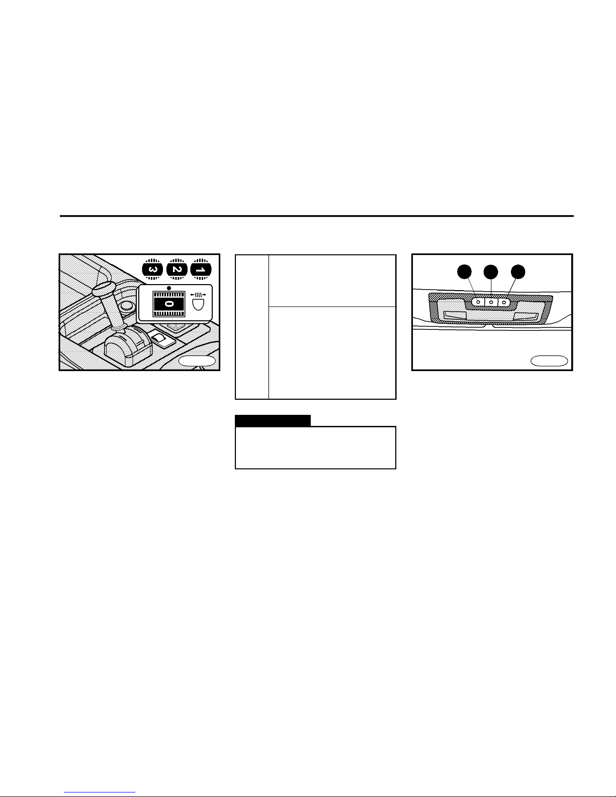
n Use the thumbwheel to change the
headlights beam inclination.
n The basic adjustment of headlamps
has been performed on the unloaded
vehicle (the control thumbwheel mark
is against zero).
n Payloads for the respective vehicle
version are mentioned in table Weights
and axle loads.
2 3
1
FN0260
n Bulbs of the dome light are turned
on/off by switches situated in the light
directly.
n Use the switch (item 1) and (item 2)
to turn on/off the light on the driver´s
side.
n Use the switch (item 3) to turn on/off
the light on the co-driver´s side.
Warning!
The driver is obliged to adjust the
headlamps depending on the
instantaneous vehicle load.
Page 30
D E S C R I P T I O N
30
Socket / cigarette lighter
Digital clock
*
Sun visors
FN0270
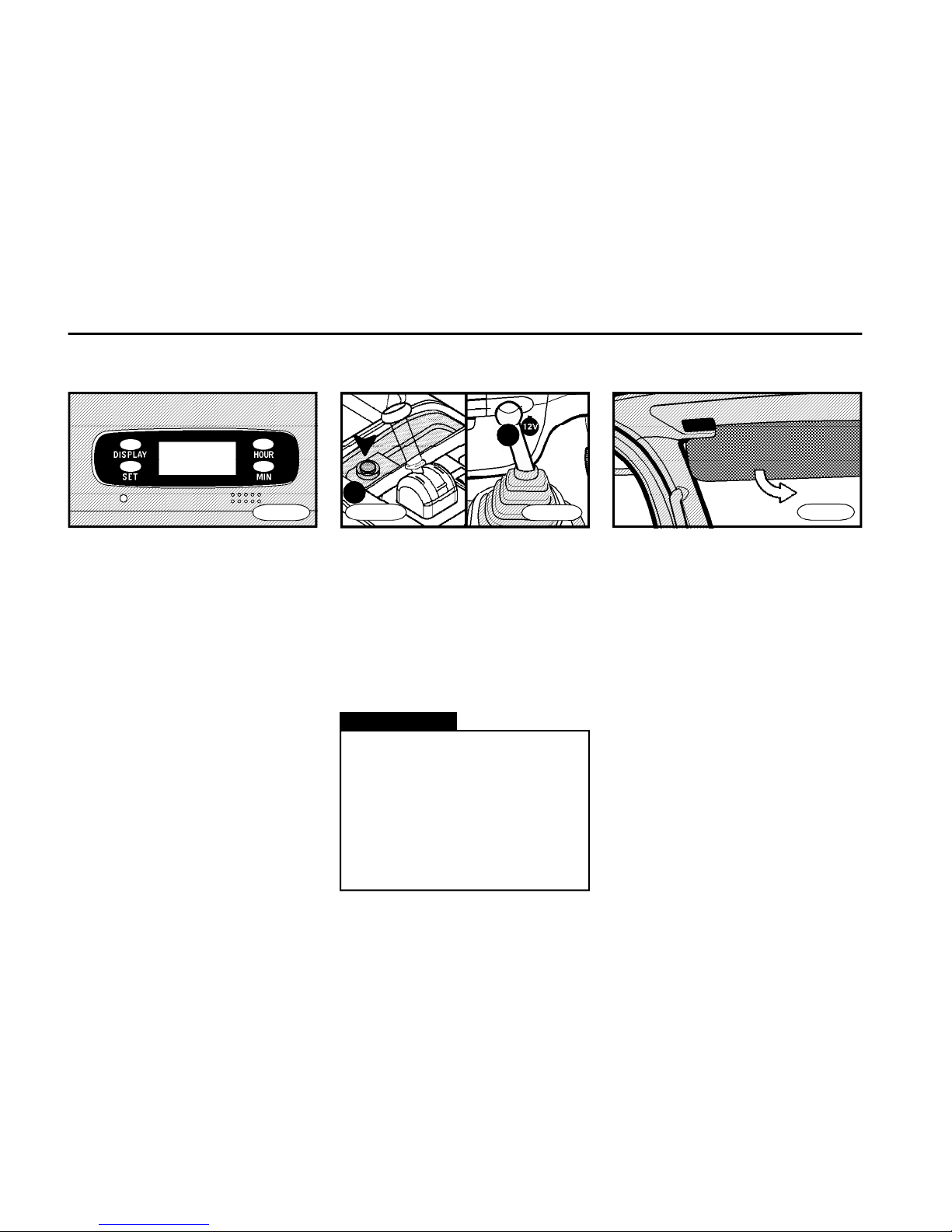
n Use button "HOUR" to set hours.
n Use button "MIN" to set minutes.
n Use button "SET" to zero minutes to
whole hours.
n The button "DISPLAY" will show the
clock when the ignition is in "LOCK"
position only. The clock displays only
when the button is hold depressed.
FN0290
n Sun visors are situated above the
windshield in the cabin ceiling.
n They can be tilted as desired.
n Adjust the sun visors to protect you
against sun glare.
A
B
FN0015a
FN0280b
n The socket (item A) can be used for
cigarette lighter only.
The socket (item B) can be used for 12 V
appliances.
n Push the knob in to switch on the cigarette lighter. When the spiral is ready for use,
it will spring back. Pull out the lighter and use
it immediately (the heating spiral will loose
the thermal energy soon).
Warning!
n It is forbiddent to use the cigarette lighter socket for other applieances, the electroinstallation
might be damaged.
n Pay attention not to burn yourself
when handling the cigarette lighter.
n If the lighter does not spring back
after about 30 seconds, it must be
removed not to burn through.
Page 31
D E S C R I P T I O N
31
Ashtray Clothes hooks, glove
compartment
Cup holder
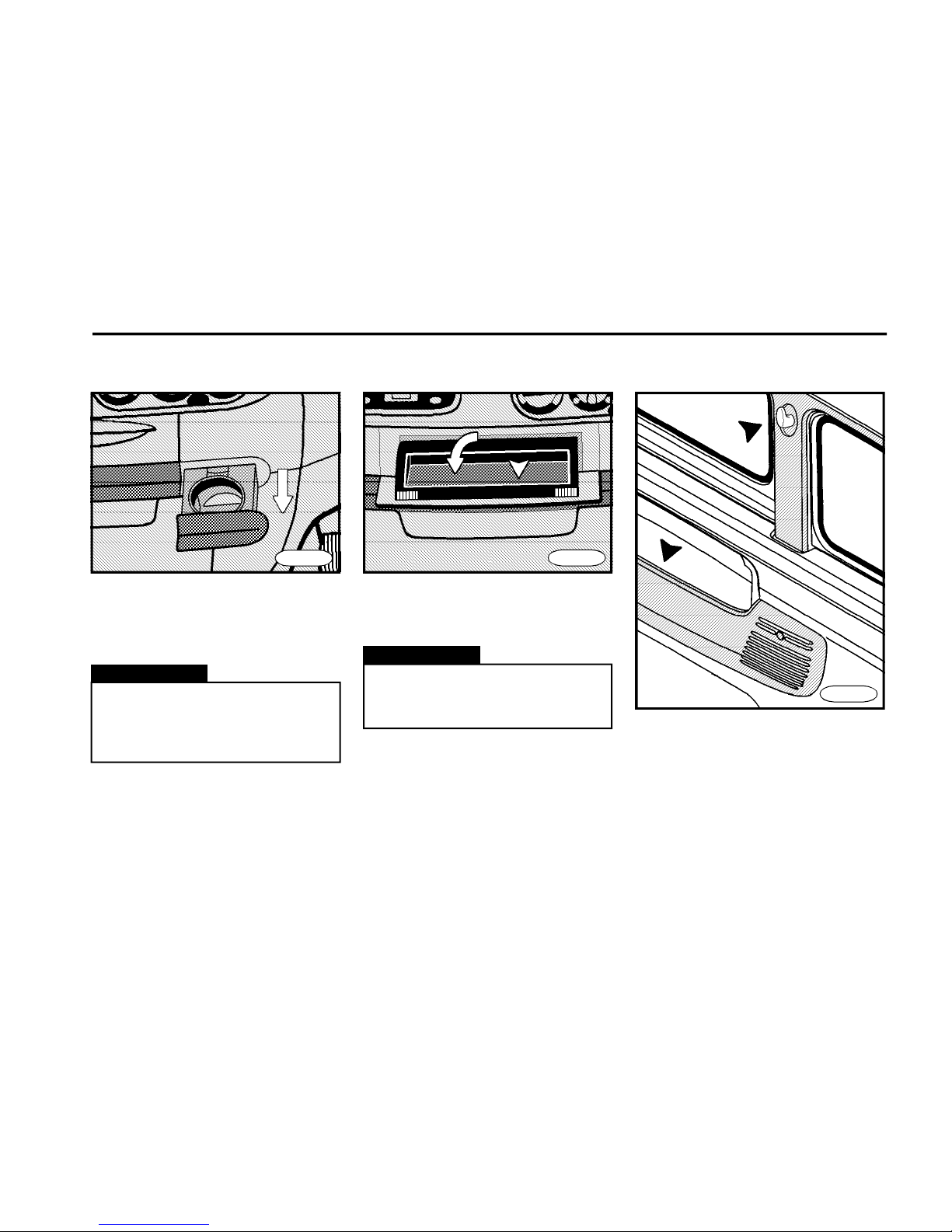
n To slide the holder out, push it and
release.
n After use, slide it back.
Warning!
n Do not use the cup holder if the
vehicle is in motion.
n Do not use the cup holder to
hold other objects.
FN0300
FN0310a
n Pull it to open it.
n To clean it, remove the sheet insert.
Never put paper and other
flammable objects in the ashtray
- danger of fire!
Warning!
FN0320
Page 32
D E S C R I P T I O N
32
Warning!
You should check a proper bonnet
locking whenever you move off.
FN0345
FN0330
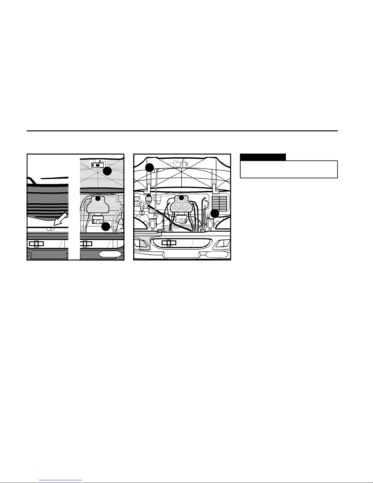
Opening the bonnet
n Push the bonnet in its lower part,
press the release lever (item 1) to left.
n Raise the bonnet.
n Take strut out of holder (item A) and
insert the strut end in hole (item B) to
secure the lifted bonnet.
Closing the bonnet
n Raise the bonnet slightly.
n Unhook strut from hole and put it in
holder (item A).
n Tilt the bonnet in the vertical position
and push its lower edge until it clicks
into lock (item 2).
n When the bonnet snaps in, you can
hear it.
Bonnet
2
1
B
A
Page 33
D E S C R I P T I O N
33
FN0360
FN0350n
Tools and equipment
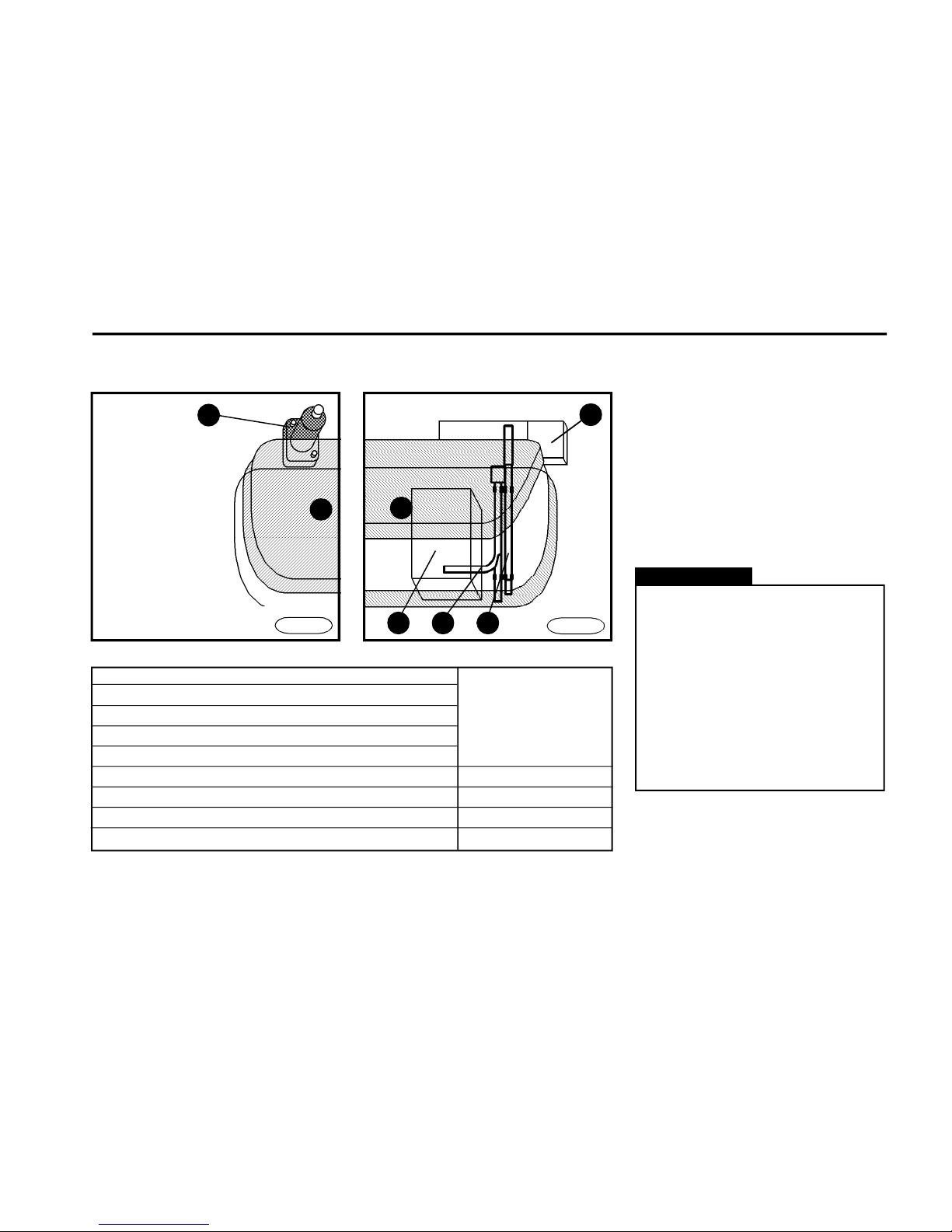
A - co-driver´s seat
B - driver´s seat
n Tools and equipment are placed
under the co-driver´s seat and are
accessible after tilting the seat cushion.
n The hydraulic jack is attached to the
cab floor behind the driver´s seat.
n Tools must be attached firmly.
Warning!
n Tools, which is not stored properly,
may cause a personal injury or disturb
you by vibrations during driving.
n The jack delivered with the vehicle
is determined to be used with this
vehicle model only. It must not be
used to lift other vehicles or other
loads.
n Tools and equipment must be
attached properly on the move or
during the cabin tilting.
Wrench 30 x 30
Lever adaptor item1
Box with bulbs
First aid kit
Warning triangle item 2
Lug wrench item 3
Rod for jack and cabin tilting item 4
Hydraulic jack item 5
Wrench 24 x 24
431
2
b
5
A
Page 34
D E S C R I P T I O N
34
FN0390
Hydraulic cabin tilting
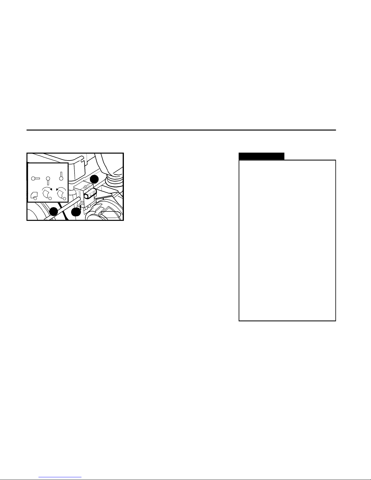
Cabin lowering
n Move the distributor lever (item 3)
into vertical position downwards.
n Pump until locks of the rear location
are closed (cabin rests down in place
and is locked).
n Move the distributor lever (item 3)
into horizontal position.
Cabin tilting
n Move the distributor lever (item 3)
into vertical position upwards (see
schema on the pump).
n Insert rod (item1) into lever of the
hydraulic pump (item 2) and pump.
Hydraulic locks of the rear location will
open and cabin starts to tilt itself.
n The cabin must be tilted fully to its
tilted position - a partial tilting is not
allowable for entering beneath the
cabin.
n Let the distributor lever be in vertical
position with the cabin lifted.
3
1
3
FN0395
2
Instructions for cabin
tilting
Warning!
n Prior to tilt the cabin, shut the
engine off and shift into neutral.
n Set the vehicle parking brake.
n Secure the objects which are
placed inside the cabin and shut
the doors properly .
n Prior to start tilting, we recommend to open the bonnet.
n Take an extreme care when tilting.
n Be very careful when working
beneath the tilted cabin.
n It is not allowed to stay ahead of
the cabin tilted.
n It is not allowed to stay beneath
the cabin if tilted partially.
n The necessary workshop height to tilt the cab is 3,000 mm and
3,800 mm with the additional superstructure.
n If the vehicle is equipped with
the safete bar of the tilted cab, it
has to be always used!
Page 35
D E S C R I P T I O N
35
Cabin tilting
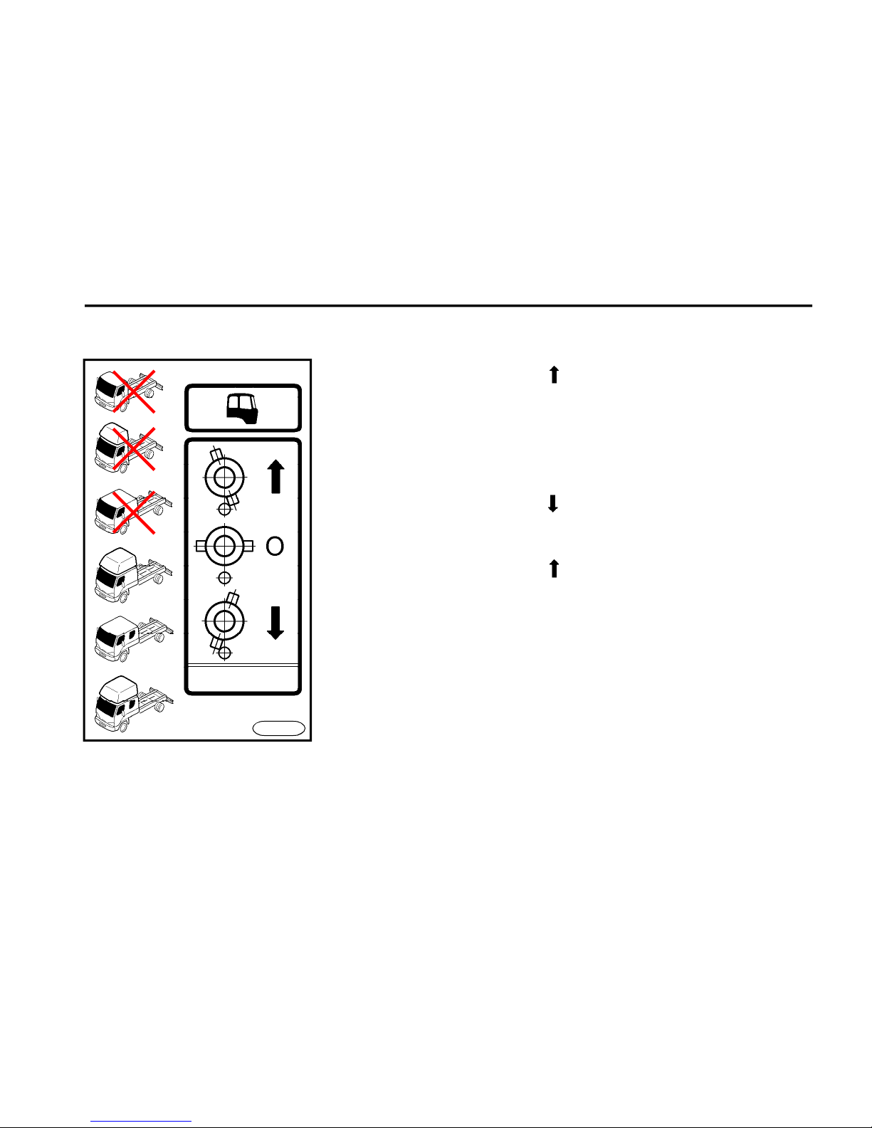
n Move the distributor into position.
n Pump until the cabin is tilted
completely (cabin will not fall over its
zero point).
Note: The cabin starts to raise itself
only after several lever strokes.
Cabin lowering
n Move the distributor into position
n Continue to pump until the locks click
in place and until you feel an increased
resistance on the lever.
n Move the distributor into position.
n Go on pumping by about 15 strokes
to adjust the position of the cabin pin
into a centre of the oval hole in the
cylinder eye.
n Move the distributor into position O.
FN0391
Cabin tilting at special versions
Page 36
D E S C R I P T I O N
36
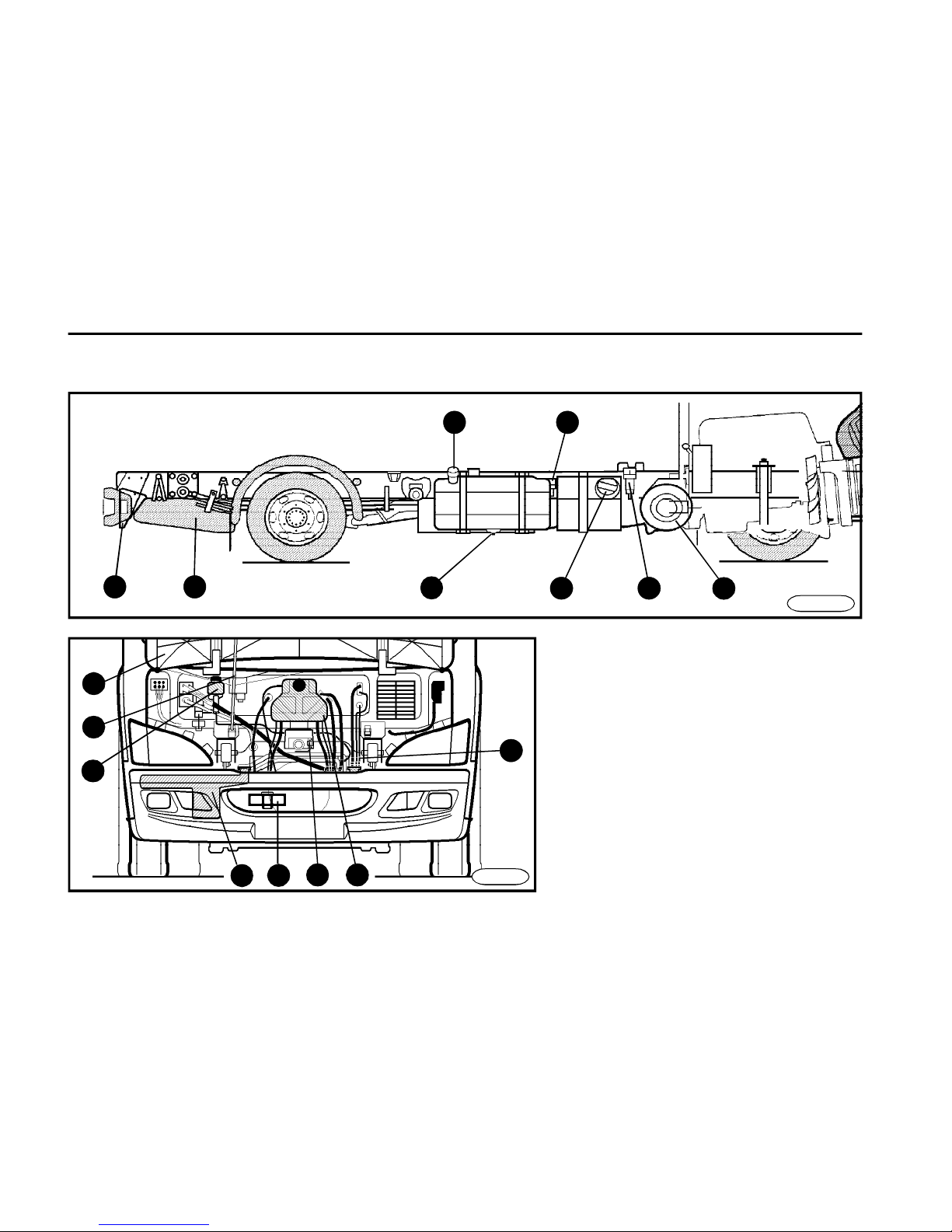
Chassis c/w cabin
1 Strut
2 Bonnet
3 Bonnet lock
4 Front coupling (for towing)
5 Washer tank
6 Clutch tank
7 Expansion tank
8 Fuel tank filler neck
9 Fuel tank drain plug
10Air filter
11Power-steering tank
12Spare wheel (four positions -
vehicle version dependent)
9
1011
1221
FN0404
22
8
23
24
6
5
4
3 7
1
2
FN0345
13
Page 37
D E S C R I P T I O N
37
14
16
20
15
20
19
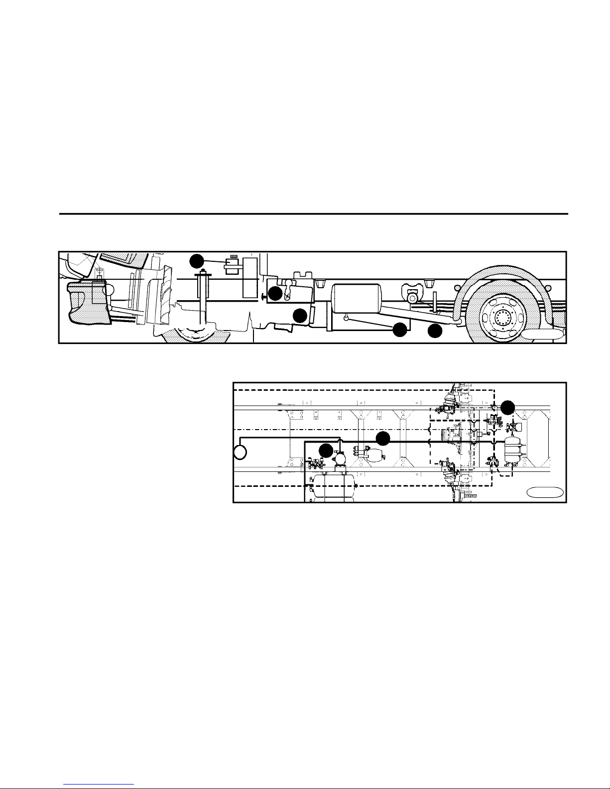
13Oil dipstick
14Gearbox
15Propeller shaft
16Air pressure regulator
c/w air drier
17Drain valve (2x)
18Regenerating air reservoir 4.5 l
19Brake pressure regulator
20Battery case c/w circuit breaker
21Wheel chock
22Fuel filter
23AdBlue fluid tank filler neck
24Air intake filter into the SCR unit
17
11
FN0422cu
19
18
16
FN0431a
Page 38

O P E R A T I N G I N S T R U C T I O N S
38
Maintenance
n To achieve a maximum use
value, economic and safe operation and maximum possible
service life, it is necessary to
carry out all maintenance works
at regular intervals as stipulated in the Service Booklet.
n The vehicle maintenance
must be carried out by autho-
rized service stations, which
have been acquainted with
the vehicle design, do their
work on a professional level,
have the necessary equipment and are in direct contact
with the manufacturer.
n The running-in of a new vehicle or vehicle after the general
overhaul is terminated after
covering 3,000 km (practically,
the vehicle engine will reach
the maximum possible output
after covering several further
thousands of kilometres).
n During the running-in period, do not run the engine
above 3/4 of its top speed or
at maximum fuel delivery under low engine speed.
n Avoid full throttle starts,
running the engine at high
speed and abrupt stops.
n Do not run the cold engine
at high speed.
n Do not let engine labor.
Downshift when engine no
longer runs smoothly.
n Vehicle must not be loaded extremely.
Vehicle runningin
Warning!
The way of running in the
vehicle has a great influence upon its service life.
n For the sake of proper
operation the engine brake
has to be switched on
(switched off) at least once
a week. Its lifetime will be
prolonged by this measure.
n The differ. lock should
be engaged / diseng. once
a week at least. Its service
life will be increased.
Warning!
n engine lubricating oil level – check/top-up
n urea (AdBlue) level – check/top-up
n drive belts + belts tensioner - check/correct
n fuel – check/top-up
n fuel-water separator – drain
n crankcase breather tube – inspect
n cooling fan – inspect
n engine coolant level – check/correct
n intercooler - check condition
n air cleaner – inspect
n air intake piping – inspect
n brake fluid in clutch booster circuit – check/top-up
n brake fluid in steering power circuit – check/top-up
n brakes and parking brake – check
n air tanks – drain (after trip)
n If the draining air contains excessive amount of water it is
necessary to change air drier filter
n tyres – check pressure and condition
n cab – secure in locks at rear
n hood – secure in lock
n fluid level in tank of washers – check/top-up
n outside lamps, indicators and brake lamps – check
n head lamps – adjust tilt with regard to load weight
n check for possible leakage of fluids (oils, brake fluid, ... etc.)
– by sight – on the spot where your vehicle was stopped after
last trip
n In case of towing a trailer it is necessary to check the trailer
connection to towing coupling, connection and functionability
of electrical wiring and air brake hoses.
Check before the drive
Page 39

O P E R A T I N G I N S T R U C T I O N S
39
Warning!
Starting the engine
n Insert the ignition key and turn in
"ON" position. Indicator and warning
lights as shown in the illustration on the
next page will come on.
n Starting the engine is possible only
with no gear shifted in gearbox. Do not
depress the accelerator pedal.
n When the glow plug warning lamp
has gone out (applies to cold and even
hot engine), start the engine by turning
the ignition key to "START" position
and hold it for a while (the engine will
crank when holding the key in this position), until the engine starts running,
however, for 10 seconds as a maximum. When starting repeatedly, keep
the interval of min. 30 s between individual starting attempts.
Warning!
n When the indicator and warning lights of battery charging,
parking brake, engine - stop, engine - warning; engine - maintenance, SCR and ECAS do not go out
after starting the engine, do not
move off .
n The vehicle must not be put in
motion in any way unless the battery circuit breaker is on and the
ignition key is inserted into ignition
switch and turned in position "ON".
The steering is unlocked in this
position. Before you move off,
check whether the steering wheel
is free to turn.
n Do not run the cold engine at
high speed - it could be damaged.
n Should the indicator and warning lights of brake system malfunction, parking brake, engine stop, engine - warning, engine maintenance, SCR and ECAS be
still on after turning the ignition to
"ON" position even after a short
while, you must not move off - find
out the cause of the defect per
Chapter "Troubleshooting".
n Use the winterized Diesel fuel
and engine oil of the viscosity grade in accordance with climatic
conditions in the winter months.
n After starting the engine, release the
key, it will automatically return to "ON"
position. After a regular engine run has
been achieved, the glowing and charging indicator lights must go out. If not,
find out the cause of the defect according to chapter Troubleshooting.
Page 40
O P E R A T I N G I N S T R U C T I O N S
40
During driving
n It is not allowed to drive without the
engine running and the gear shifted.
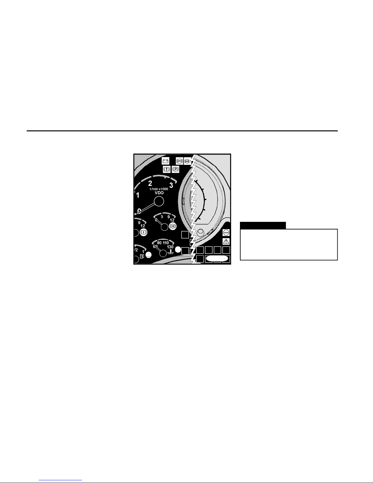
n Watch the indicator and warning
lights on the move from time to time.
n If any of the warning lamp shown in
the picture above comes on while driving, it is necessary to stop the vehicle
(at the soonest with regards to the traffic circumstances for the sake of safety). In addition, if the engine - stop light
comes on, it is also necessary to shut
n After the vehicle is set in motion,
check the efficiency of the service
brake. Checking the braking efficiency
is important especially in winter, after
washing the vehicle or after fording
(passing through a deeper pool of
water). Brake up the vehicle repeatedly
to allow a quick drying out of the brake
system.
n Do not brake sharply - on one hand
the tires and brake system would be
worn quickly and too much, on the other
hand this way of braking would endanger the other motorists.
n Depress the accelerator pedal gradually.
n Depress the clutch pedal as far as it
goes.
n Shift to gears smoothly not to stress
the engine extremely. Before engaging
the reverse run, put the vehicle to a full
stop not to cause damage to gearbox.
n Before shifting to reverse gear at the
gearbox model ZF 6 S 850 it is necessary to wait 3 to 5 seconds after depressing the clutch pedal (to allow stopping
of shafts in gearbox) and only after that
engage the reverse gear.
the engine off.
Then proceed according to Chapter:
Troubleshooting.
If the coolant temperature indicator light
comes on, it is necessary to reduce the
vehicle speed, to downshift, and stop
the vehicle as soon as possible and
allow cooling down the engine by the
enhanced speed (1,200÷1,500 rpm).
Warning!
If the fuel reserve indicator light comes
on (item 1), it is still about 16 l fuel in the
fuel tank.
If the yellow control light ECAS* starts
glowing, then the rear part of the vehicle
is outside the driving height position
(level) Applicable for version with pneumatick suspension only.
In any case it is not allowed to shut
the engine off when the coolant
temperature indicator light comes
on.
FN044cu
Page 41
O P E R A T I N G I N S T R U C T I O N S
41
Stopping the engine
Warning!
n Turn off the battery master
switch only 30 seconds after turning off the ignition to allow data
processing by ECM (Engine Control Module) and to allow air to blow
through the AdBlue injection system into the exhaust system (noise from the area of AdBlue tank
may be heard). If the instruction as
above is not followed a fault may be
reported by warning lamps or the
SCR system and/or damage of the
SCR system may be caused due to
insufficient removal of AdBlue residues (possible crystallization or
freezing) and thus causing blockage of it.
n Turn the ignition key from position
"ON" to position "ACC" to stop the
engine.
FN0441
Warning!
Do not let the engine run at idle or
at speed to 1,000 rpm without load
for more than 10 minutes. When
the engine is running for a long
time in these regimes, the temperature of the combustion space
will drop so that the fuel cannot be
burned completely. This may result in creation of carbon in the
surrounding of holes of injection
nozzles and piston rings what may
lead to damage the engine. In addition, low temperatures will cause that all oil penetrating from valve
gaskets will not burn in exhaust
channels. The oil not burned can
cause damage to turbocharger.
Idle run
Warning!
n Never shut the engine off by turning off the battery circuit breaker it may result in damage to wiring
cables and alternator.
n The ignition key may be removed from the ignition switch only
after full stopping of the vehicle.
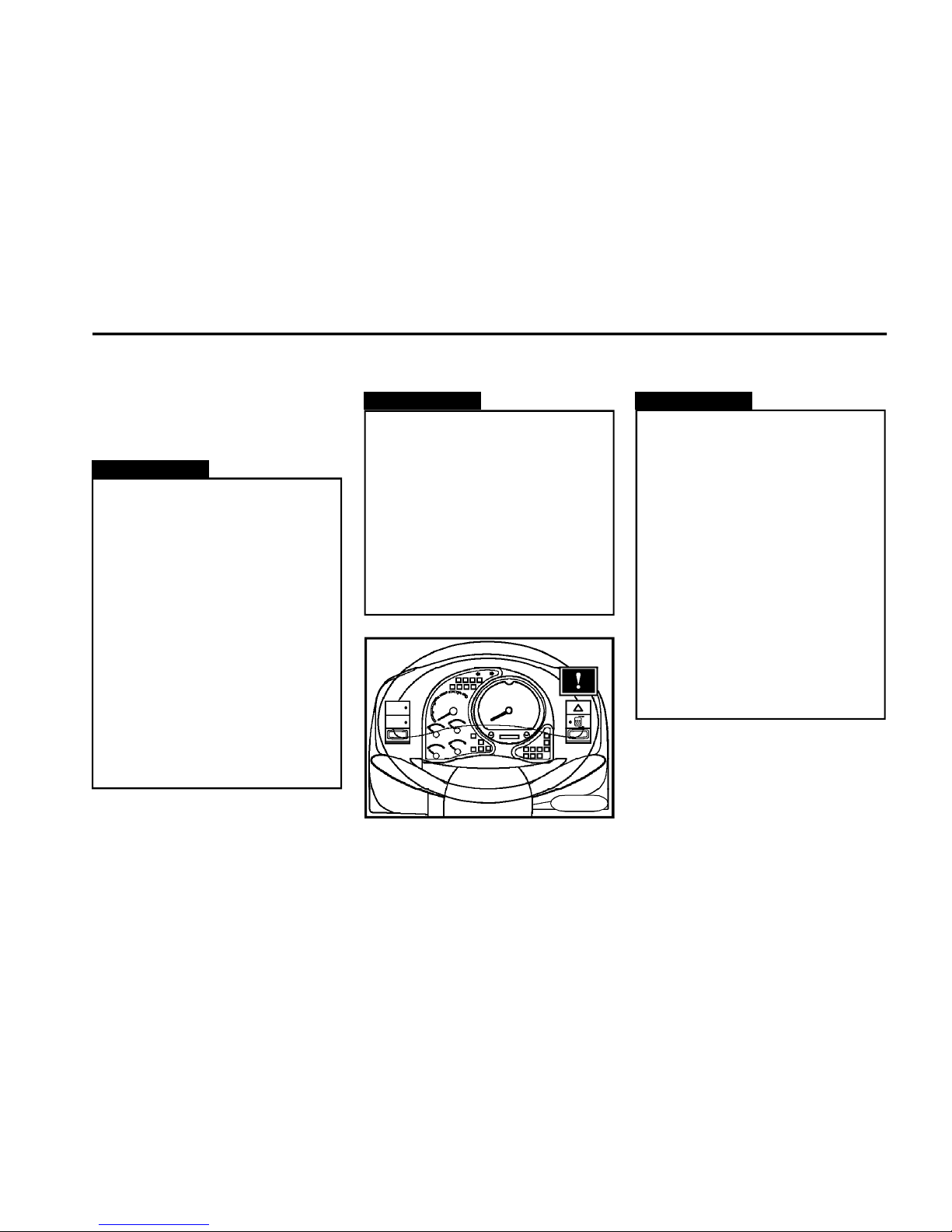
n Before stopping the engine after a full load operation, allow it
to idle 1 minute at least - see the
label on the instrument board.
Page 42
O P E R A T I N G I N S T R U C T I O N S
42
Engine
FN0482a
7 2
9
4
6 3
10
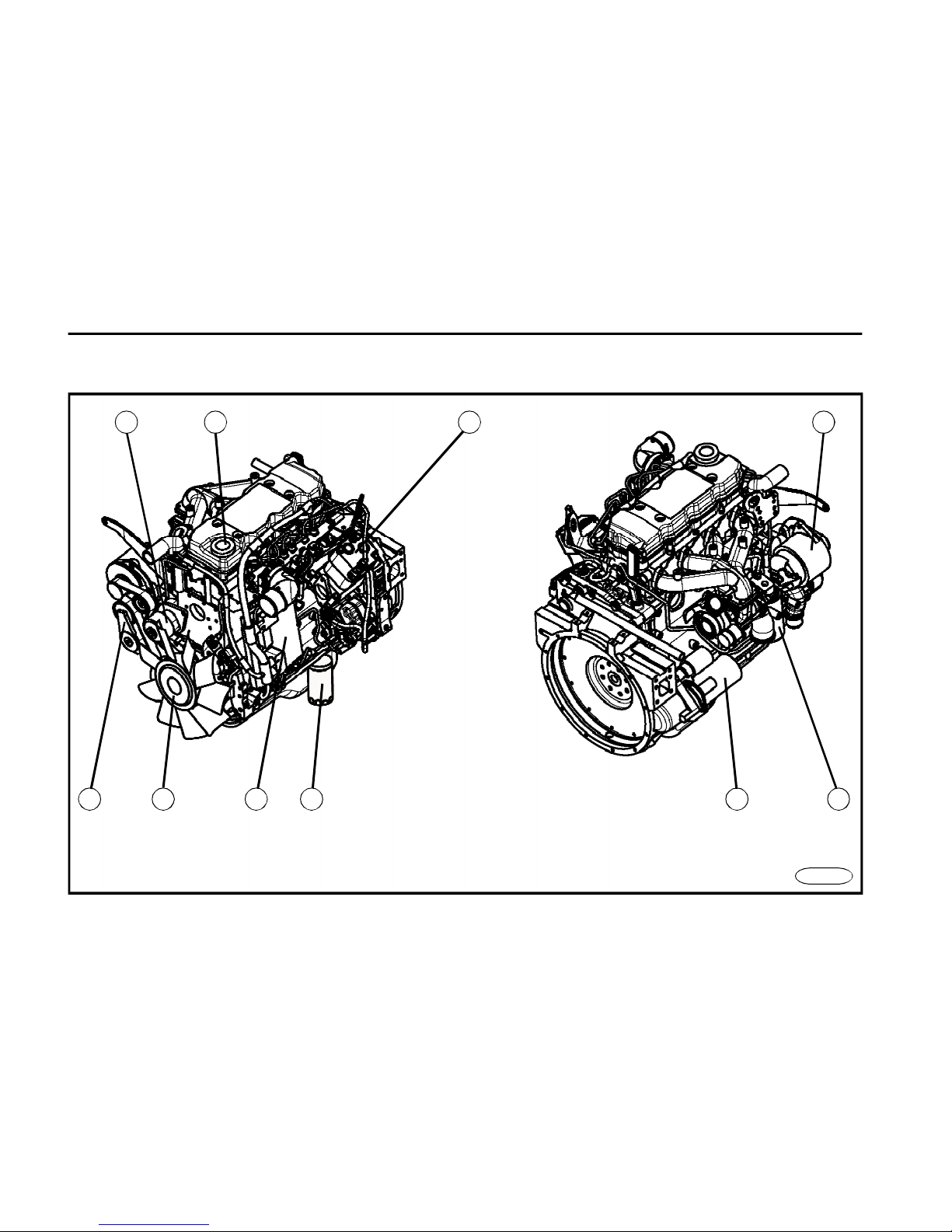
1 Alternator
2 Oil filter
3 Engine starter
4 Fuel filter
5 Engine control unit
6 Fan c/w visco-coupling
7 Tension roler
8 Water pump
9 Oil filler neck
10Compressor
1
5
8
Page 43
O P E R A T I N G I N S T R U C T I O N S
43
Cummins ISB4 160
- Diesel engine
- four-cylinder
- 16 valves
- max. power output
117 kW / 2,500 rpm
Cummins ISB4 185
- Diesel engine
- four-cylinder
- 16 valves
- max. power output
136 kW / 2,500 rpm
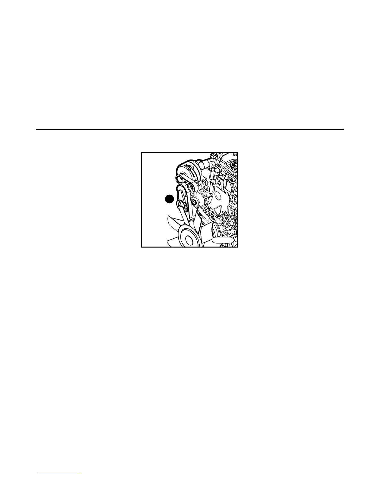
n The belt is tensioned automatically
by the pulley (item A), which cares of the
constant tension.
n When the belt has been damaged, it
must be replaced immediately.
Belt tensioning
A
FN04821a
Page 44
O P E R A T I N G I N S T R U C T I O N S
44
FN0450
n Have the oil changed and oil filter
replaced at the authorized service
station.
n The insufficient oil level will cause damage to engine.
n Keep the environment clean
when handling the oil.
n When it looks that oil quality got
worse (presence of water), contact the authorized service station
promptly.
n Dispose of used oil in accordance with environmental regulations.
Warning!
Checking the oil level and kind
of oil
n It is necessary to check the oil level
before each drive (the oil is consumed
a little by the vehicle operation).
n The vehicle must stand on level
ground to check the oil level.
n Check the oil level before starting
the engine when the oil level is stabilized.
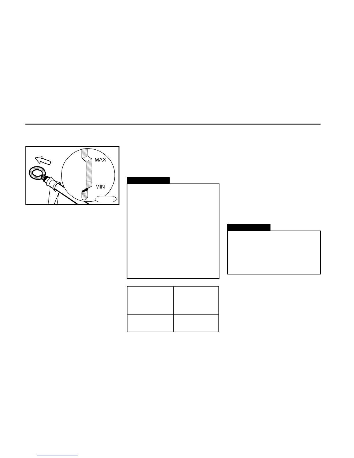
n Pull dipstick out, wipe it clean with a
rag and push it in a hole all the way.
n Pull dipstick out again. The oil level
is correct when it is between marks on
the dipstick. It must not be above the
MAX mark, because the engine could
be damaged.
n Add the oil in time not to allow the oil
level to drop below the MIN mark.
Lubrication system
Engine oil Recommended
specification oil viscosity
grade
A C E A S A E
E5 10 W - 40
or E7 5 W - 40
Warning!
n The manufacturer is not
responsible for damages caused
by neglecting the oil economy .
n The manufacturer does not
provide any guarantee for engines
damaged by use of oil additives.
n The oil class, which was filled in the
engine in the manufacturing plant, is
mentioned on a sticker on the cap of oil
filler hole.
n Always use the approved engine
oils only.
n Use of special oil additives is forbidden, because some additives combined with brand name engine oils may
result in impairing the function resulting in damage to engine.
n Always add the oil of the same quality.
n For the oil change intervals see the
Service Booklet.
Page 45

O P E R A T I N G I N S T R U C T I O N S
45
Filling the engine with oil
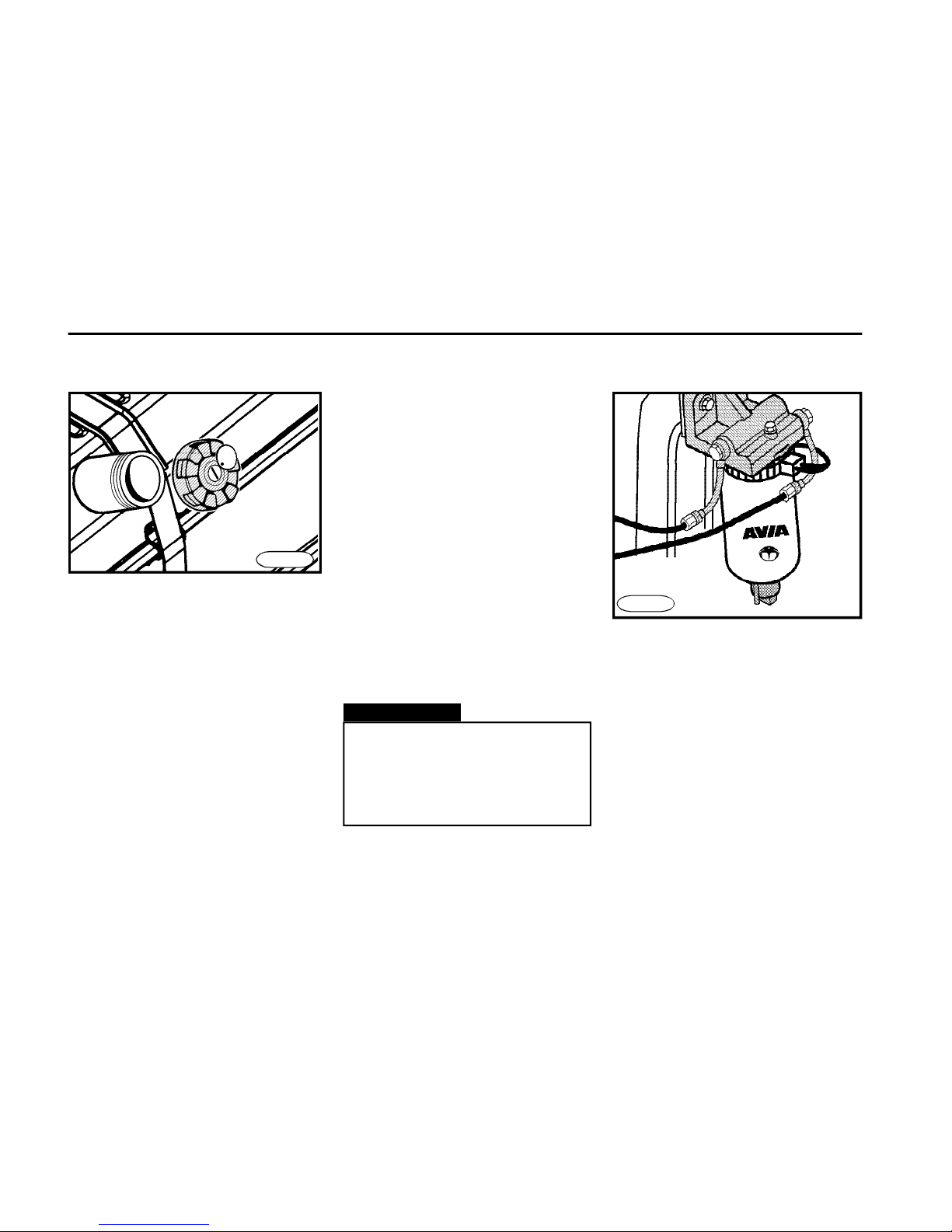
n Unscrew the filler neck cap.
n Keep the environment perfectly clean
when adding the oil.
n Do not fill the oil above MAX mark.
n When the oil level is correct, mount
the cap again.
FN0460cu
Turbocharger
n Keep the environment clean and
avoid mechanical damage to impeller
of centrifugal blower by sucking in the
mechanical dirt (for example during
operation without installed coarse air
filter).
n Before stopping the engine from a
full load operation, allow it to run at idle
for one minute at least (see the label on
the instrument board) to secure the
cooling down of turbocharger by oil and
thus to avoid burning-in of carbon on
the turbocharger shaft.U
FN0441
n If the turbocharger is defective,
have it repaired at the authorized
service station.
n To increase the service life of
turbocharger, keep the air filter
and the whole intake manifold
perfectly clean.
Warning!
Page 46
O P E R A T I N G I N S T R U C T I O N S
46
Fuel tank Fuel
FN0520
n To prevent air from entering the fuel
system, never allow the fuel tank be
completely empty.
n The fuel tank capacity is 120 l (160 l
*,
200 l*).
The float device is installed in the fuel
tank. The fuel reserve in tank is checked
by the fuel gauge on the instrument
board.
n The minimum fuel reserve makes
16 l (20 l*) as indicated by the signal
bulb at the fuel gauge.
n The fuel gauge is operative with
ignition turned in "ON" position.
n The fuel tank neck is fitted with a
lockable cap.
Warning!
n Do not allow all the fuel be
pumped out of the fuel tank.
n The use of bio-Diesel is not
permitted.
n It is not allowed to add petrol
into Diesel fuel.
n Your Diesel engine has been specifically designed to operate on Diesel
fuel per ČSN EN 590 (656506). Prefer
using the Diesel fuel with a low sulphur
content (0.05% hm), which is available
on the market.
n In the winter months (from November 1 to March 31) you should use the
Diesel fuel whose filtering ability (CFPP
specification) meets the climatic conditions.
n To assure the operation under low
temperatures, you may put additives
into Diesel fuel, which improve the filtering ability under low temperatures.
Perform the mixing according to manufacturer´s instructions.
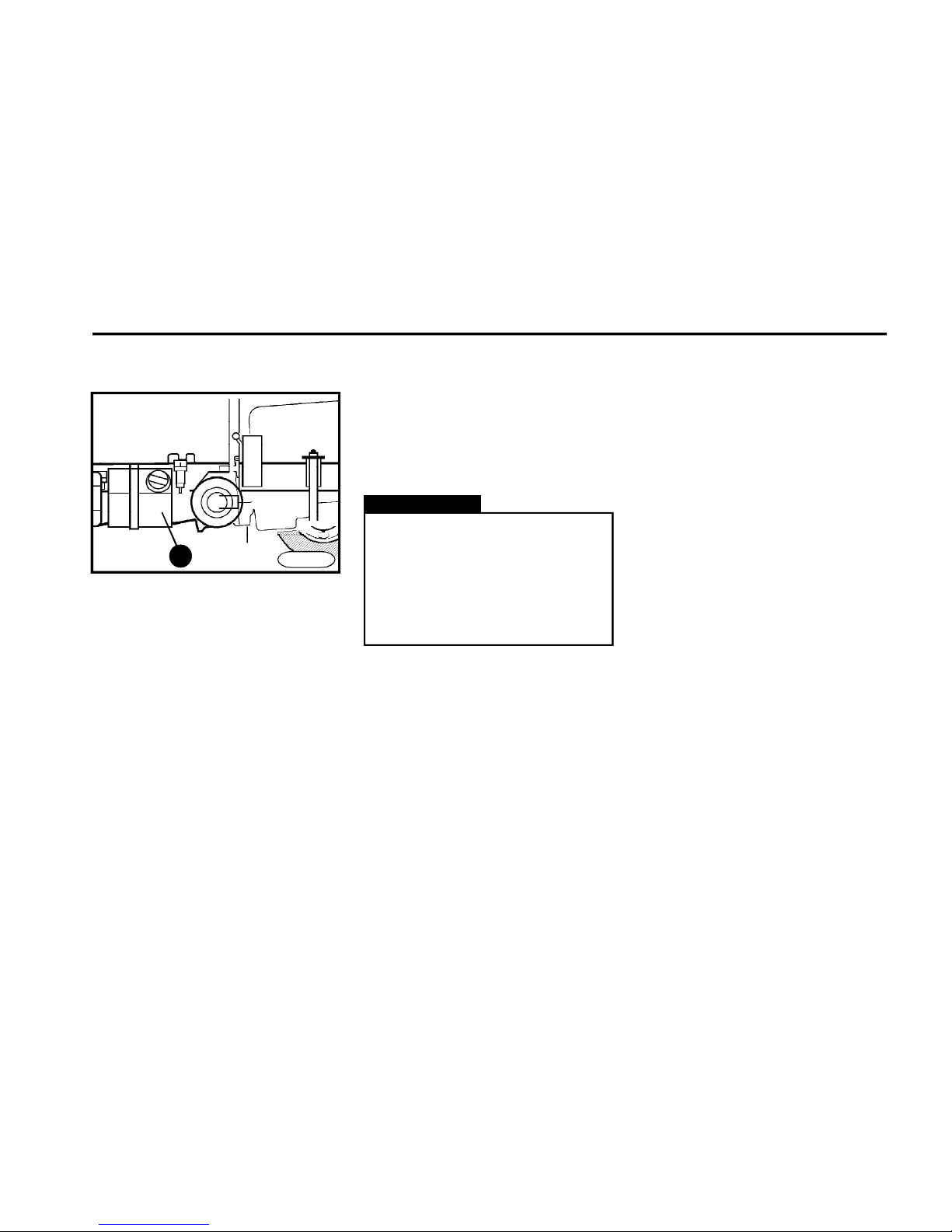
Draining the fuel filter
Unscrew drain bolts on the fuel filter
bottom to allow draining of water from
the fuel filter. When all dirt particles drip
out, screw the bolts again.
frame
FN0474
Page 47
O P E R A T I N G I N S T R U C T I O N S
47
AdBlue fluid
n Use exclusively the AdBlue fluid determined for the vehicle operation (standard DIN 70070).
n It is not permitted to replace the AdBlue fluid with other product or to mix it
with other product. The catalytic converter system reducing the exhaust emissions could suffer a damage.
n Always remember to handle the
AdBlue fluid with care. The AdBlue is a
corrosive agent, which must never
come in contact with other chemicals.
n If you stain your skin or hit your eyes
with the AdBlue fluid, rinse the stained
spots with a lot of water.Call a doctor if
needed.
AdBlue fluid tank
FN0403cu
1
n The tank “usable capacity” (item 1) is
23 l (total capacity 30 l).
In the tank the fluid level measuring
device is installed. The shortage of fluid
is indicated by the indicator light on the
isntrument board.
n When the AdBlue fluid level drops
below 3 l of the usable capacity, the
warning lamp „engine - warning“ comes on and when the AdBlue fluid level
of the usable capacity drops below 10 l,
the warning lamp „SCR system mal-
function“ starts flashing
n Make it a habit to check the AdBlue
fluid level in tank at every Diesel refuelling.
AdBlue consumption fluctuates from
0,5 up to 3% of fuel consumption
depending on ways how your vehicle
is being operated and on engine
load.
Warning!
If the warning lamp “SCR system
malfunction” is on you must not
drive the vehicle – exhaust emissions do not meet required values.
Driving with the illuminating warning lamp is stored in the engine
ECM.
Page 48
O P E R A T I N G I N S T R U C T I O N S
48
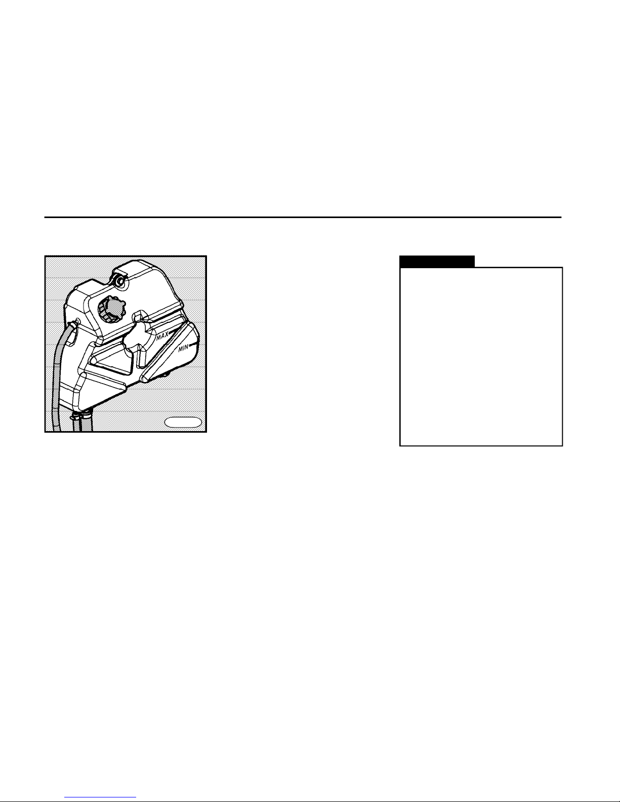
MIN and MAX marks when the engine
is cold (when the engine is warm, the
coolant level may exceed slightly the
MAX mark). If the coolant level is too
low, it is necessary to add it.
n For year round, add antifreeze
(specification ASTM 4985) and distilled
water in the ratio specified (see the
manufacturer´s instructions on the
antifreeze packing).
n All year-round use of antifreeze
protects the cooling and heating system
against corrosion and sediments. For
that reason do not reduce the
concentration of the antifreeze by
adding water even during the warm
season of the year (always add it in the
ratio with antifreeze).
n Take care not to spill the antifreeze on
the body paint.
n Before the winter season comes,
check the antifreeze in the cooling
system for condition and concentration.
n Before the summer season comes
and anytime when the face body area
has been polluted, clean the radiator
with compressed air or stream of hot
water from the engine side.
Check the expansion tank cap.
n Have the coolant changed at the
authorized service station.
n Do not open the cap of coolant
reservoir when the engine is hot danger of scalding!
n Never run the engine with the
thermostat removed.
n The expansion reservoir prevents the bleeding of the cooling
and heating circuit. Remember to
check the coolant level.
n When the engine overheats or
the coolant leaks, have it corrected by the authorized service station.
Warning!
Cooling system
FN0530
Checking and adding the coolant
n The label saying which kind of coolant has been filled, is situated on the
expansion tank or by the expansion
tank.The cooling system has been filled
with the fluid based on ethylene-glycol.
The mentioned coolants can be mixed
with coolants based on ethylene-glucol (C type).
n Check the coolant level at regular
terms.
n The coolant level must be between
Page 49
O P E R A T I N G I N S T R U C T I O N S
49
FN0540n
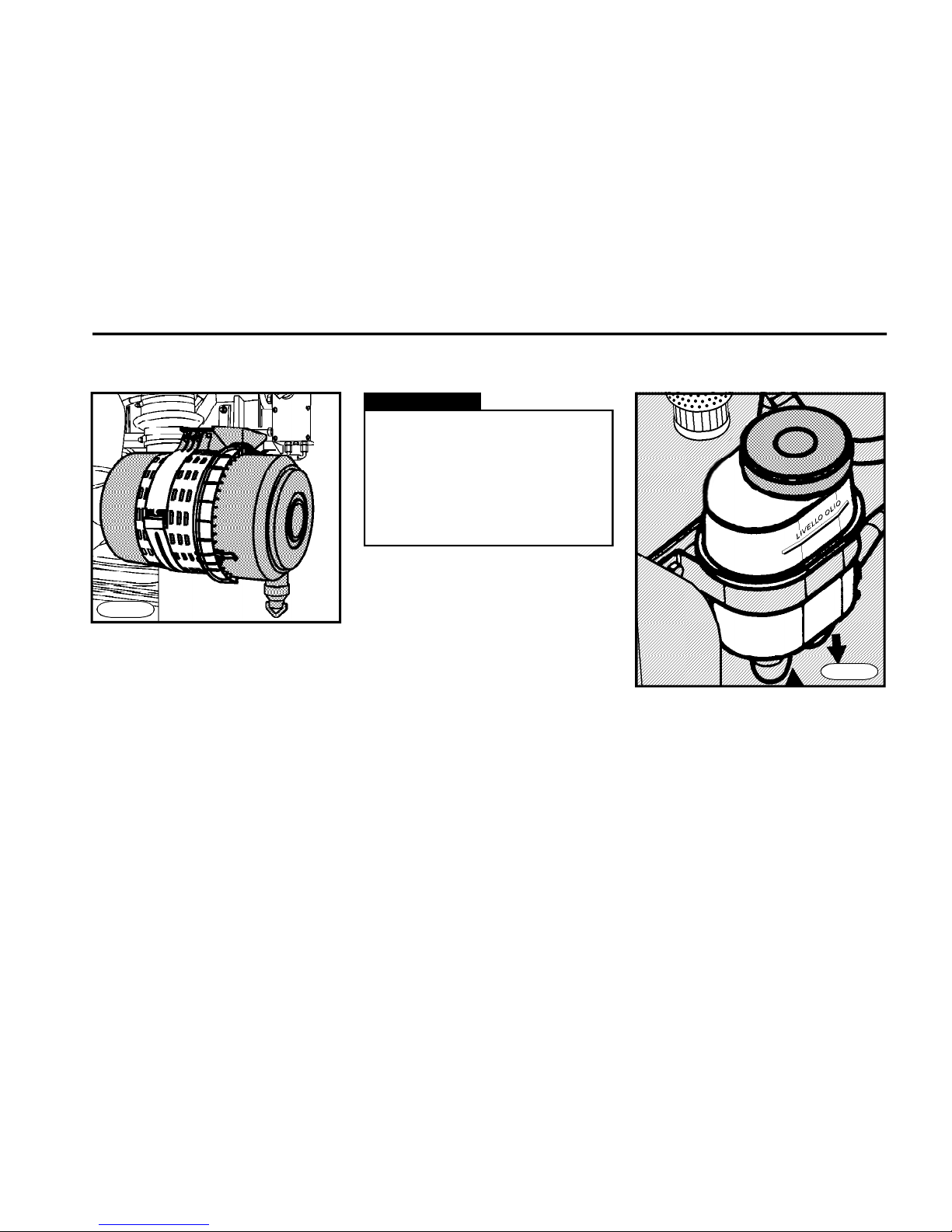
n The air filter cartridge replacement
interval is stated in the Service Booklet.
n The clogged filter cartridge is
indicated by the indicator light. When it
comes on, you should visit the
authorized repair shop immediately.
n Without regard to the pollution
signalling, keep the replacement
interval as mentioned in the Service
Booklet.
n The condition of the air filter and
intake manifold have a great influence
upon the service life of turbocharger.
Warning!
n Have the air filter cartridge replaced at the authorized service
station.
n When the vehicle is operated in
very dusty conditions, reduce the
replacement intervals accordingly.
Air filter Steering
FN0550
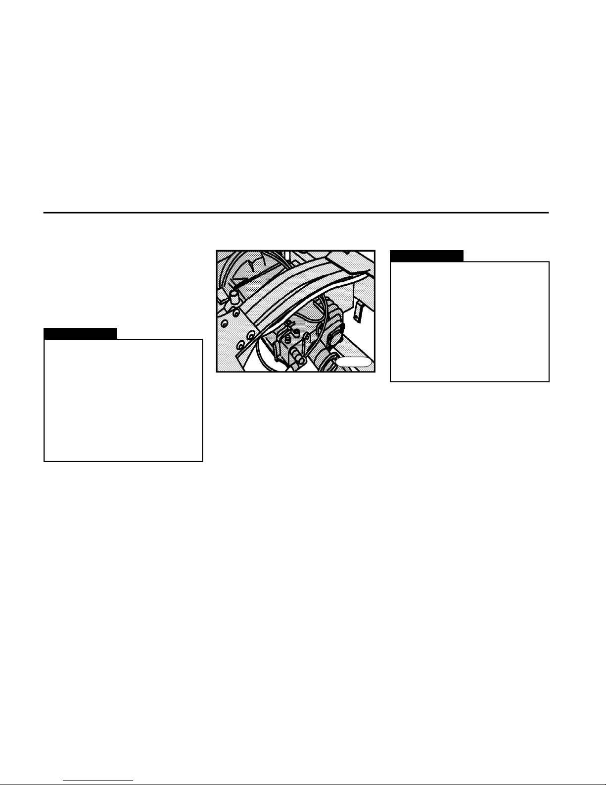
Checking and adding the
steering oil
n Check the oil level regularly.
n The oil level in the tank must reach the
"LIVELLO OLIO" mark. If it drops below
this mark, it is necessary to add the oil of
the ATF D II specification into circuit.
n If the steering play was found out, it is
necessary to have it adjusted and/or repaired at the authorized service station.
Page 50
O P E R A T I N G I N S T R U C T I O N S
50
Warning!
n Have the oil changed and oil
filter replaced at the authorized
service station.
n If the oil needs to be refilled too
often, visit the authorized service
station.
n Do not run the engine when there
is no oil in the power steering
hydraulic circuit.
n Keep the environment clean
when handling the oil.
n If the steering effort increases
considerably during the vehicle
operation, stop immediately and check
the oil level in the tank of monoblock
hydraulic power steering and check the
hydraulic circuit for condition.
Gearbox
n Have the oil changed at the
authorized service station.
n When the vehicle is towed with
engine at standstill and no gear
shifted, disconnect the propeller
shaft (at the rear axle) to avoid
damage to gearbox due to
insufficient lubrication.
n Do not start the engine when
there is no oil in gearbox.
Warning!
FN0560
n Check oil level and quality in gearbox
during service inspections.
n Check the gearbox for leaks. If you
find out leakage, visit the authorized
service station.
Page 51
O P E R A T I N G I N S T R U C T I O N S
51
Clutch
n The clutch is actuated hydraulically
and completed with the air booster.
n In case that the fluid circuit has been
aerated (clutch will disengage poorly),
it is necessary to look for the authorized
service station.
n When the clutch plate has been worn,
the clutch system will be set automatically what is evident by discharging
the fluid into tank (the fluid volume
increases in the tank).
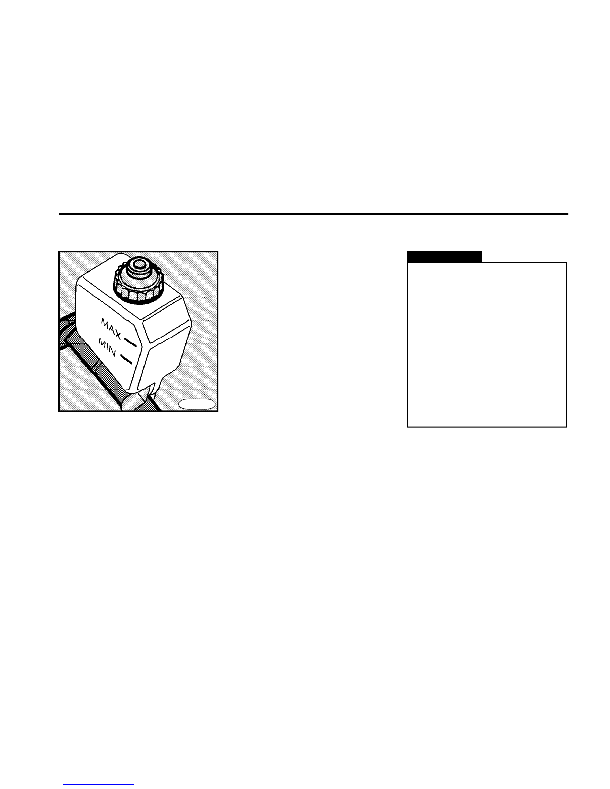
Checking and adding the fluid
n Check the fluid level in circuit
regularly.
n The fluid level must be between MIN
and MAX marks. If it drops below MIN
mark, add the fluid of the specification
DOT3, DOT4, DOT4+ or SAE J 1703.
Warning!
n Have the fluid changed at the
authorized service station.
n Keep the environment clean
when handling the fluid.
n When air leaks from the air system (for example during a longterm vehicle storage), the air booster will be put out of function what
results in increasing the force needed to press down the clutch pedal.
n If the fluid needs to be added too
often, contact the authorized service station.
n The fluid is harmful to health.
FN0600
Page 52
O P E R A T I N G I N S T R U C T I O N S
52
Rear axle
Transmission Recommended
oil specification viscosity grade
A P I S A E
GL - 5 85 W - 140 H
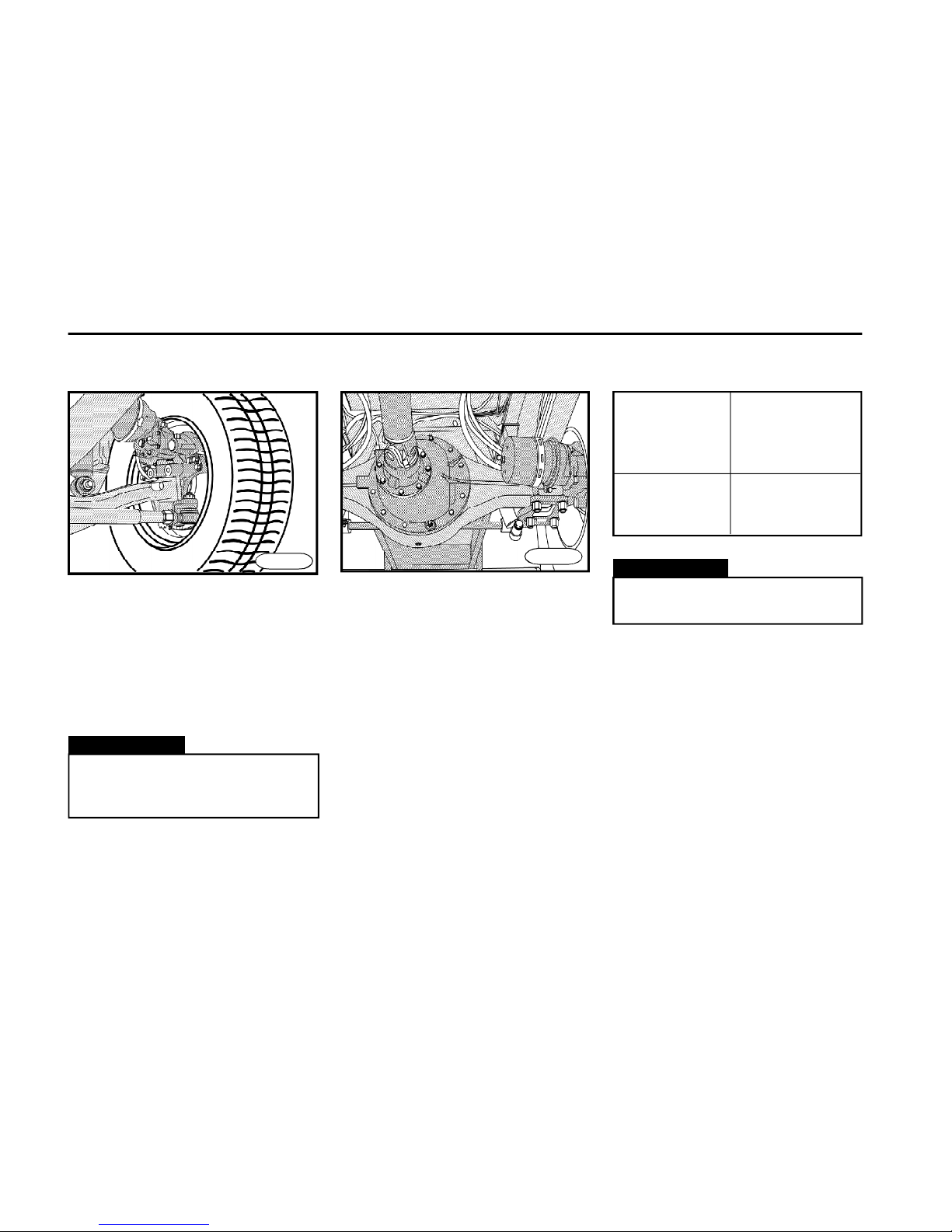
n Check the oil level and change the
oil in axle final drive housings during
service inspections.
n Visually check the axle final drive
housings for leaks only. If you find out
leakage, have it repaired at the
authorized service station.
FN0610n
Warning!
Have the oil changed at the
authorized service station.
Warning!
Entrust some authorized service
station to carry out all repairs,
refills or adjustments.
n If you notice that tyre treads wear
unevenly on the front axle, check and/
or have the front axle geometry adjusted
at the authorized service station.
n The life of shock absorbers and their
function depend on the way of driving
and kind of operation.
Front axle
FN0620
Page 53
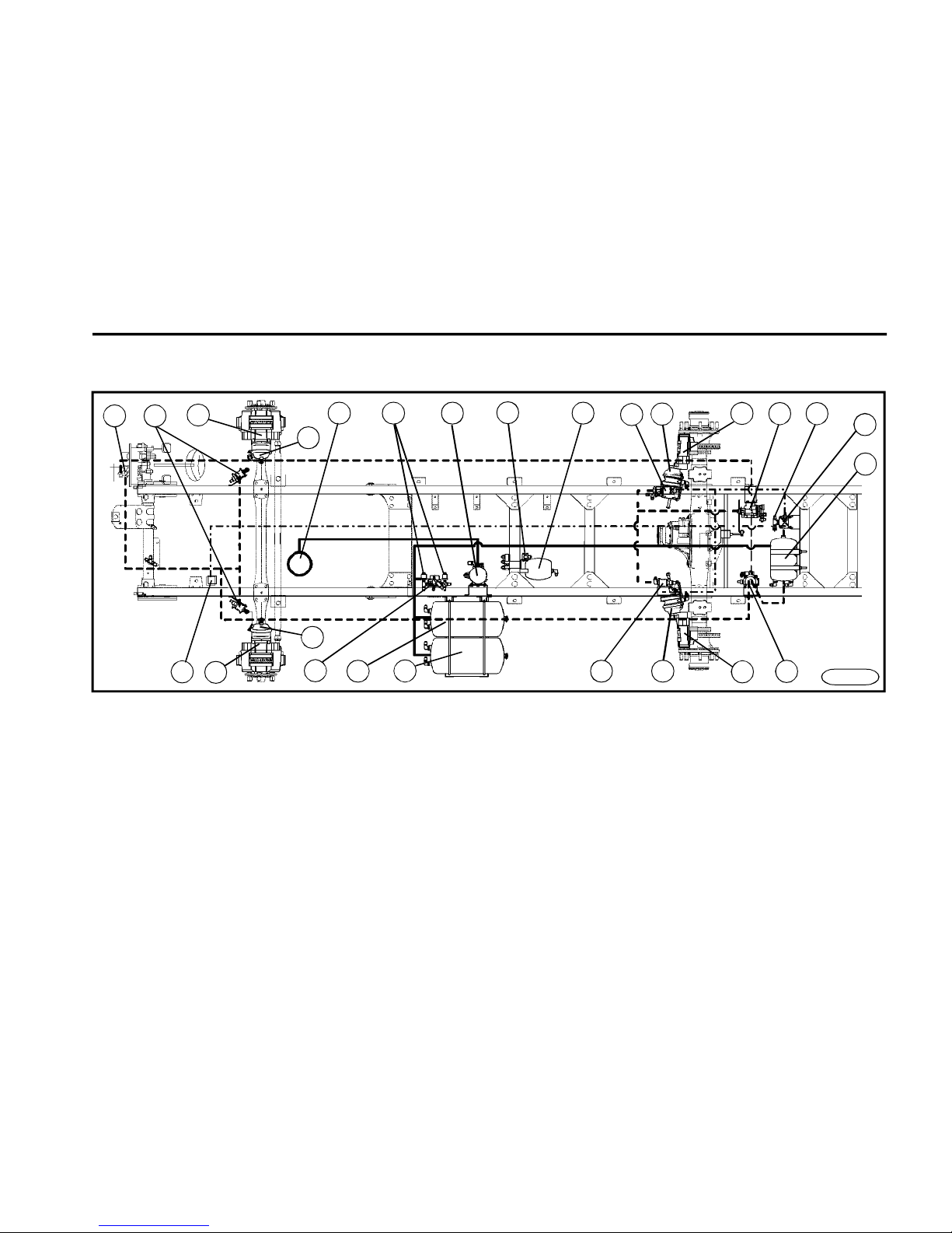
O P E R A T I N G I N S T R U C T I O N S
53
1Compressor
2Air pressure regulator c/w air drier
3Air reservoir 4.5 l
4Four-way relief valve
5Air reservoir 30 l
6Air reservoir 30 l
7Master brake valve
8ABS valve (1st circuit)
9ABS valve (2nd circuit)
10Automatic brake pressure regulator
11Combined brake cylinder
12Manual brake valve of parking brake
13Switch of minimum air pressure of spring loaded cylinder
14Front axle brake system
15Rear axle brake system
16Air reservoir of parking brake circuit
17Valve relay
18Trailer brake valve
*
19ASR valve
*
20Minimum air pressure sensor in circuits of service brake
21Membrane brake cylinder
Brake system
15
14
2 3
5 6
7
10
17
16
18
8
8
1
9
11
11
12
FN0650
FN0431a
4
20
19
13
14
15
21
21
Page 54
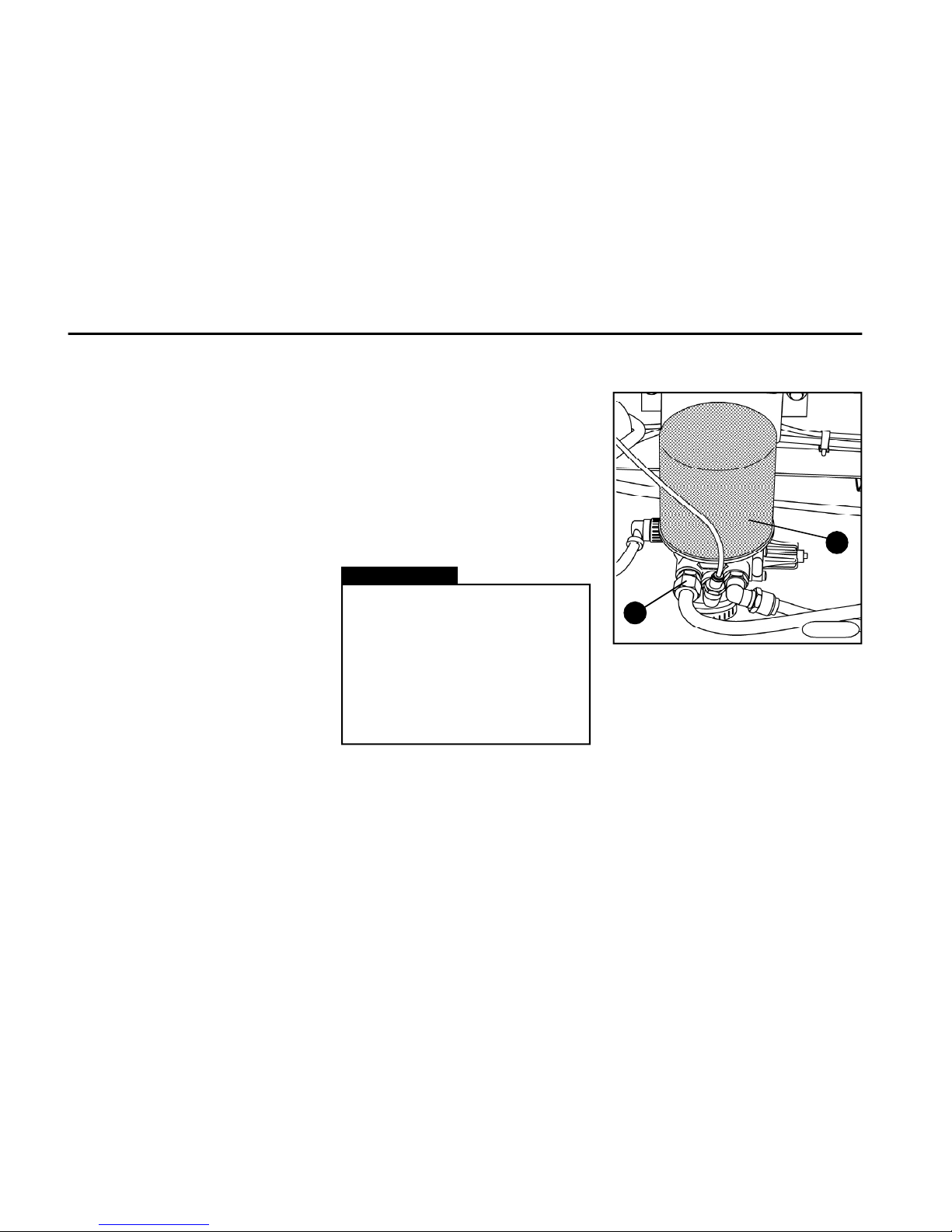
O P E R A T I N G I N S T R U C T I O N S
54
Service brake
Air pressure in circuit of service
brake
Nominal pressure
0.85 ± 0.02 MPa (8.5 bar)
Minimum pressure
0.55 MPa (5.5 bar)
Warning!
If it is not possible to reach the
minimum level of the air pressure
in the brake system, there is a
fault in the service brake circuit
which must be promptly repaired
at the authorized service station.
It is not permitted to continue to
drive the vehicle until the fault is
repaired.
n Disc brakes are mounted on both
axles.
n The service brake system is dualcircuit, controlled pneumatically.
n Vehicles are standard equipped with
ABS, the ASR is installed as option.
n The first circuit of the master brake
valve controls the rear brake system.
n The second circuit of the master
brake valve controls the front brake
system.
n The automatic brake pressure
regulator controls the braking force of
rear axle wheels in dependence on the
vehicle load.
Correct function of the service
brake is indicated by:
1.Air pressure gauges picking up the
pressures in 1st and 2nd circuits.
2. ABS indicator light.
Air pressure regulator c/w air
drier
n This serves to clean and dry the air
supplied from the compressor and to
control the operating pressure in brake
circuits.
FN0650
2
1
FN0650n
Page 55
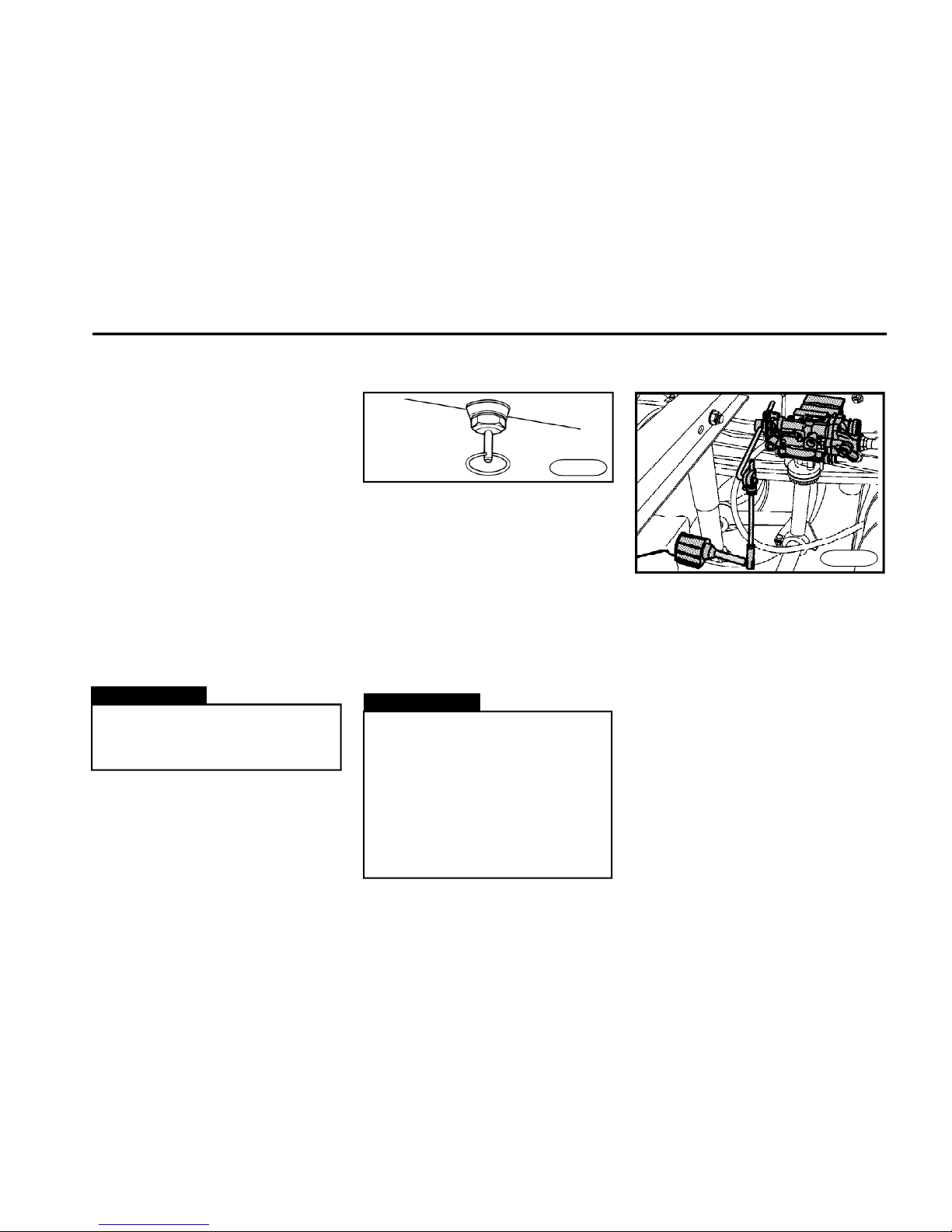
O P E R A T I N G I N S T R U C T I O N S
55
The used filter must be disposed of
in accordance with environmental
regulations (it may contain oil).
Warning!
Air drier filter replacement
(item1)
n Replace the air drier filter always
before the winter season. If you find out
water in drain valves, replace it immediately (water can be found in drain valves
during regular service inspections).
n No air pressure is allowed in the air
drier.
n Prior to start the replacement, clean
the surface of the air drier and loosen the
union nut to release the pressure (item
2) on the inlet.
n Clean the upper part of the air drier
body, gently oil the gasket of a new filter
and hand tighten to 15 Nm.
Automatic brake pressure
regulator
n The automatic load sensing valve serves to control the air pressure entering
the combined cylinder of the rear axle
dependent on the load on the rear axle.
n All adjustments must be carried out
at the authorized service station. During operation, check visually the connection of regulator lever with axle, a
free travel of the regulator lever and
instrument tightness.
n The vehicle operator only gives the
adjusting values of the brake pressure
regulator according to vehicle version
in case that real values do not respond
to ones given on the label in the cabin.
FN0660n
Draining the condensate
from air tanks
n In all air tanks of the pneumatic suspension and pneumatic brakes a water
condensate accumulates, which has
to be drained after every journey.
n When draining, a full operational air
pressure must be in the system. Water
condensate must be drained by swinging the handling levers of draining
valves placed at the bottom part of air
tanks.
FN0655
n In winter season and humid
weather the draining has to be
done several times a day..
n If the draining is not done regularly, as a consequence the vehicle safety can be compromised
and instruments can be damaged;
for such cases warranty is not
applicable.
Warning!
Page 56
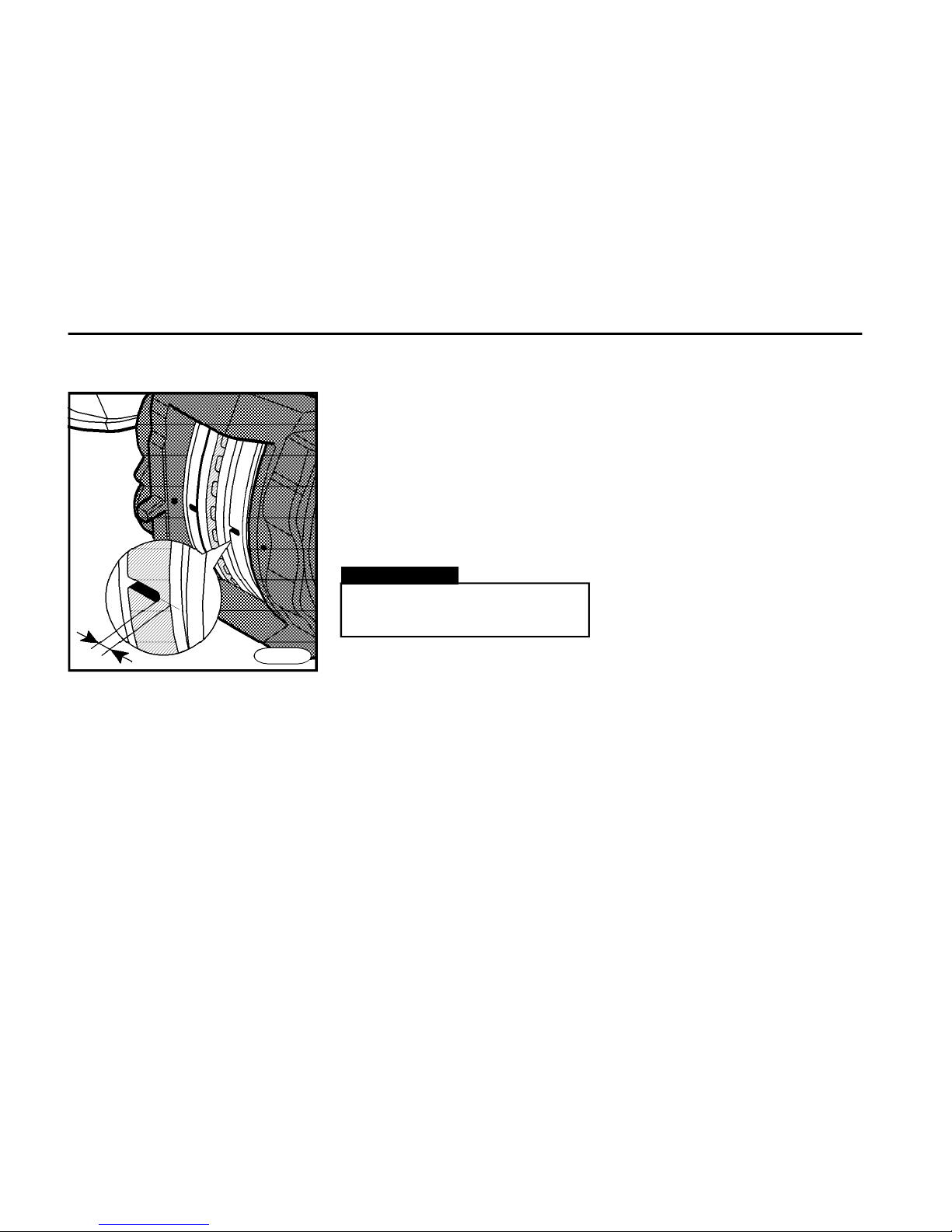
O P E R A T I N G I N S T R U C T I O N S
56
Checking the brake lining
Wheels brake system
n Disc brakes are mounted on both
axles.
n Brake pads have been worn if the
indicator light on the instrument board
and diode on the check module under
the glove box of the instrument board
come on.
Warning!
Only the authorized service
station may perform the repla-
cement of brake pads.
FN0670
n Brake pads need to be replaced
when there is no gap in their centres
(see the figure).
n The minimum thickness of the brake
pad friction material is 2 mm.
n The minimum total thickness of the
brake pad is 9 mm.
n Replace the pads with ones of the
approved type only.
2mm
Brake system inspections
n To assure a correct function of the
brake system, it is necessary to check
it for a good condition at regular terms.
n Daily:
-drain the air reservoirs
n Once a month:
-clean the air reservoirs from outside
and check whether they have not
corroded and if attached properly.Replace the damaged air
reservoir immediately.
-check the compressor intake
manifold and check whether the air
filter has not been polluted.
-check the screwed connections and
manifolds of the whole brake system
for leaks.
-check the pipes and hoses for
a good condition. If damaged, carry out
a replacement.
Page 57

O P E R A T I N G I N S T R U C T I O N S
57
Anti - Blocking - System
The ABS system enhances considerably the active driving safety of the
vehicle. Compared with common brake systems, it keeps a good driving
maneuverability even at sudden braking on wet roads because the wheels
will not block.
However, you cannot expect that the
braking distance will be reduced with
ABS under all circumstances!
The ABS has been designed not to
shorten the braking distance, but to
keep the control ability over the vehicle.
If the circumferential wheel speed is
too low related to the vehicle speed and
the wheel tends to slip, the braking
pressure of this wheel will be reduced.
The braking pressure controls each
axle separately. Hereby the braking
effect will be balanced and the driving
maneuverability is kept as much as
possible.
To allow a good function of ABS, the
brake pedal must be hold depressed -
never brake up interruptedly!
n When the ignition is on, the ABS
indicator light must always come
on. If the ABS indicator light does
not go out in several seconds after
the ignition is on, or when it does
not come on at all and/or comes on
during driving, the system is defective and the vehicle is braked without ABS. Only the normal brake
system is operative on vehicle.
Proceed to your nearest authorized service station in that case.
n The enhanced safety which is
offered by the ABS must not tempt
you to undergo any risking!
n All repairs and interventions in
ABS may be performed by the authorized service station only.
Warning!
ASR*
n The ASR system facilitates the acceleration and driving when the road
adhesion is decreased. At the moment
when the wheel on the driving axle
starts to slip, it will be braked up and
hereby the torque on the wheel with
better adhesion conditions will be increased. At the same time engine
speed (revolutions) and torque is being decreased.
n While the ASR is being in operation
the ASR warning lamp is illuminating.
n If the ASR indicator light does
not go out in several seconds after
the ignition is on, or when it does
not come on at all and/or comes
permanently on while driving, the
system is defective and ASR is
probably out of function.
Proceed to your nearest authorized service station in that case.
n When ASR is not functional, the
normal vehicle operation is not influenced.
n All repairs and interventions in
ASR may be performed by the authorized service station only.
Warning!
Page 58
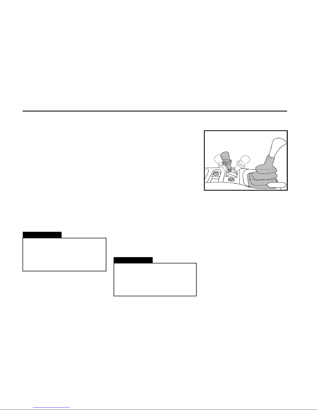
O P E R A T I N G I N S T R U C T I O N S
58
Emergency brake
Warning!
Any unprofessional intervention
into the brake system is not allowed
and all repairs and interventions
must be entrusted to authorized
service stations.
Warning!
The use of emergency brake always
means the endangering of the vehicle operation because the emergency braking effect is always much
lower than that of the service brake.
The brake system has been designed
so that when one circuit is defective, the
emergency braking effect is secured.
A loss of operating braking effect
may be caused by:
n Malfunction in the pneumatic part of
the service brake due to air loss. The
defect is indicated by the decreased pressure in one of two service brake circuits.
n Defect in the pneumatic part ahead
of the four-way relief valve.
n Defect in one of four pneumatic
circuits behind the four-way relief valve.
n Defect in the electrical part of the
brake system - in the ABS system.
n Failure of the trailer brake system.
Conclusion
n Always before the set out for the
drive and when driving, do not forget
to check a good function of the brake
system so that you are watching air
gauges and warning lamps of the brake
system.
n Check a good function of bulbs of the
brake system indicator lights by turning the
ignition key from "ACC" to "ON" position
when the indicator lights must come on.
n After full operating air pressure in the
system is reached the warning lamps
must go out.
n After the indicator lights have gone
out, you may move off.
Brake system instruments
The vehicle user is obliged to carry out
the continuous inspections of the brake system to check its condition and
function. When some defect or suspicion of the defect has been found out,
have the diagnostics and possible
repair performed by the authorized
service station.
Parking brake
n The parking brake is of spring-loaded type and acts on wheels of the rear
axle.
n The energy needful to brake up the
vehicle is accumulated in the spring of
combined brake cylinder being air compressed. Air pressure will press the
spiral spring and this way the parking
brake is released.
n The parking brake is controlled by
means of the manual brake valve lever,
which is located behind the gearshift
lever.
Position of the parking brake lever
n Parking position:
FN0690a
driving
position
parking
positioncheck
position
Page 59
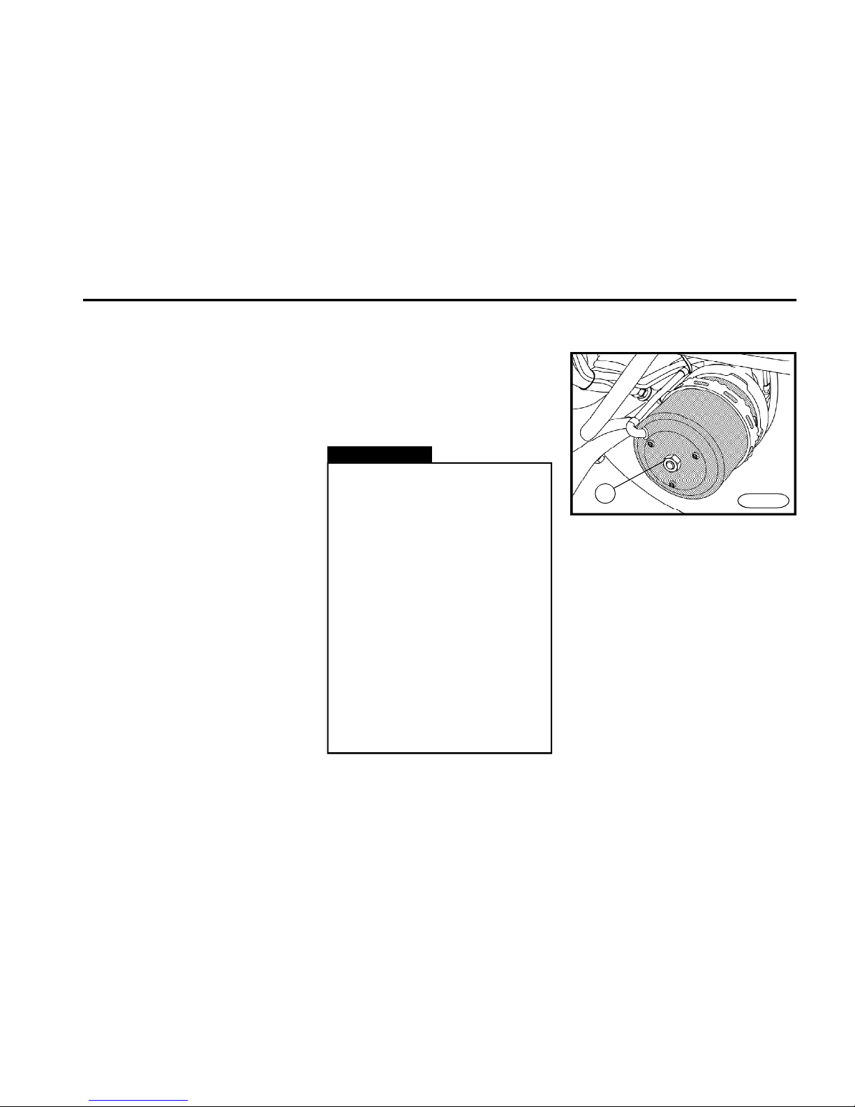
O P E R A T I N G I N S T R U C T I O N S
59
FN0700n
1
Warning!
n The use of parking brake during
driving is dangerous - danger of
loss of control and skidding. Apply
the parking brake only in case of
urgent need.
n It is not allowed to drive the vehicle when the indicator light of
minimum air pressure in the springloaded brake lights - the vehicle is
being braked up.
n Pressures in a circuit of the
spring-loaded brake:
Nominal pressure
0.85 ± 0.02 MPa (8.5 bar)
Minimum pressure
0.55 MPa (5.5 bar)
Releasing the combined brake
cylinder - for the need of towing
only
n Place the wheel chock to secure the
vehicle against motion.
n Turn the nut 1 to unscrew the stem
out of spring-loaded cylinder.
To brake up the vehicle, it is necessary
to move the manual brake lever
rearwards into the parking position
(before the parking position is
achieved, you have to overcome a point
of pressure resistance and then the
lever is automatically secured in the
parking position).
n Check position
(it applies to some vehicle versions
only)
This position is designed to check if
the parking brake system of the towing
vehicle is capable to brake up the
vehicle combination in a certain
gradient in a safe manner. A function of
the parking brake of the trailer brake is
disengaged after pushing the manual
brake lever and its displacing from the
parking position rearwards into the
check position; hereby the vehicle
combination will be braked up by the
parking brake of the towing vehicle only
(hold the lever in this position during
inspection). After releasing, the control
lever will automatically return into the
parking position.
n Driving position
After releasing, gently raise the lock
ring of the manual brake lever and move
the lever forwards into a driving
position.
Page 60
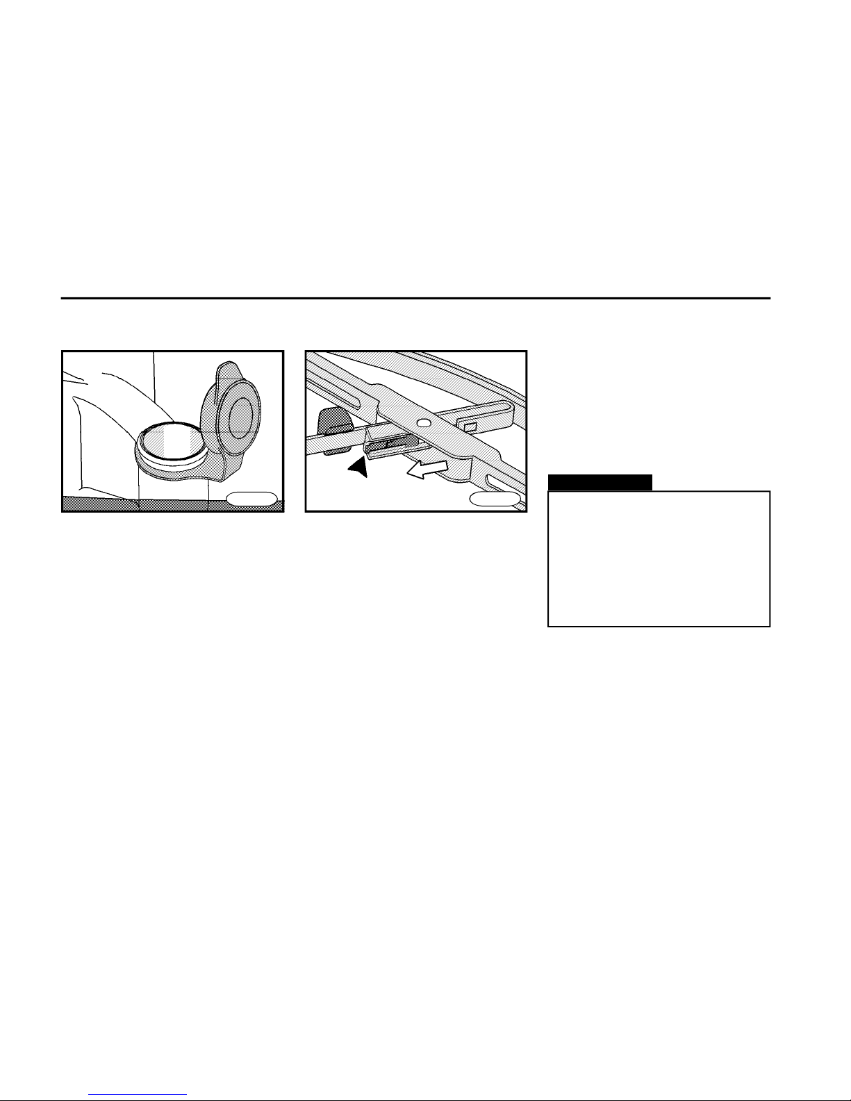
O P E R A T I N G I N S T R U C T I O N S
60
Windshield washer & wipers
Replacement of wiper blade
n Tilt the wiper arm.
n Tilt the wiper blade horizontally.
n Depress the plastic locking spring
and remove blade by pulling it from
location.
n Installation is a reverse of removal.
Fluid container
n The windshield washer container is
situated in the front bumper.
n The container capacity is 7.5 l.
n The fluid can be added after opening
the front bonnet.
n The respective indicator light
*
indicates the minimum fluid level.
n Use water with glass washer solvent
agent to add the fluid. In winter keep the
stipulated ratio not to allow the fluid will
freeze up (follow instructions mentioned
on the antifreeze package).
Warning!
n Do not use wipers to wipe dry
glass - they may scratch it.
n Do not use wipers when there
is a layer of snow on the
windshield - clean the glass first.
n In the winter months, make
sure first whether the wipers have
not frozen up to the glass.
FN0720
FN0710
Wipers
n For reasons of safety, keep the wiper
blades in a perfect condition to assure
good visibility.
n To assure good wiping, wash the
rubber blades with glass washing agent
regularly.
n On the wiper arm there are washer
jets.
n The jets can be adjusted with a
needle.
n The whole wiper arm body c/w jets
can be moved freely along the arm.
Page 61

O P E R A T I N G I N S T R U C T I O N S
61
Tyres and wheels
Wheels and wheels data
Wheels of the front axle - 2 balanced
ones
Wheels of the rear axle - 4 non-balanced
ones
Spare wheel - 1 balanced one
Disc wheel:
D 60-100: 17,5 x 6,00
D110-120: 17,5 x 6,75
19,5 x 6,75
Tyres(radial):
D60-90: 215/75R 17,5
9,5R 17,5
225/75R 17,5
D100: 225/75R 17,5
9,5R 17,5
D110-120: 245/70R 17,5
265/70R 17,5
245/70R 19,5
265/70R 19,5
235/75R 17,5 (D110)
ALL STEEL TUBELESS
n Check the tyre pressures always before you drive the vehicle. Remember
also to check the tyres if they are in a
good condition (look for the tyre repair
shop if they have been damaged).
n Tyre inflation pressures are mentioned on the plate inside the cabin and
in table in Chapter Technical Data.
n No cuts, bruises or other damages
showing the tyre casing cord are allowed on tyre treads or sides.
n In case of the uneven wear of tyre
treads on front axles, check and/or adjust the front axle wheels geometry.
n The depth of tread grooves of tyres
must be 1.6 mm at least. If tyres treads
are marked REGROOVABLE, the treads can be cut through to make them
deeper (only a specialist may perform
it).
n Only balanced tyres may be mounted
on front wheels and all wheels must be
in a good technical condition.
n Only tyres stated for the given type of
the vehicle and recommended by the
tyre manufacturer may be used on the
vehicle.
n Protect tyres against oils and fuel.
n If the vehicle is put out of operation for
a long time, it should be slightly raised
to relieve the tyres.
n The dismounted wheels (tyres)
should be stored in a dry and dark place.
n Check the tightening-up of wheel nuts
at intervals stipulated in the Service
Booklet.
n In addition, check the tightening-up
of nuts on wheel bolts after covering the
first 50 ÷ 100 km and after every wheel
removal to the torque of:
D 60-100 370 ± 30Nm (6 x M18)
D110-120 485 ± 35Nm (8 x M20)
The service life of tyres
depends on:
n way of driving and driving habits
n correct tyres inflation
n vehicle operating conditions
n geometry of front axle
n proper distribution of load on the load
space
Page 62
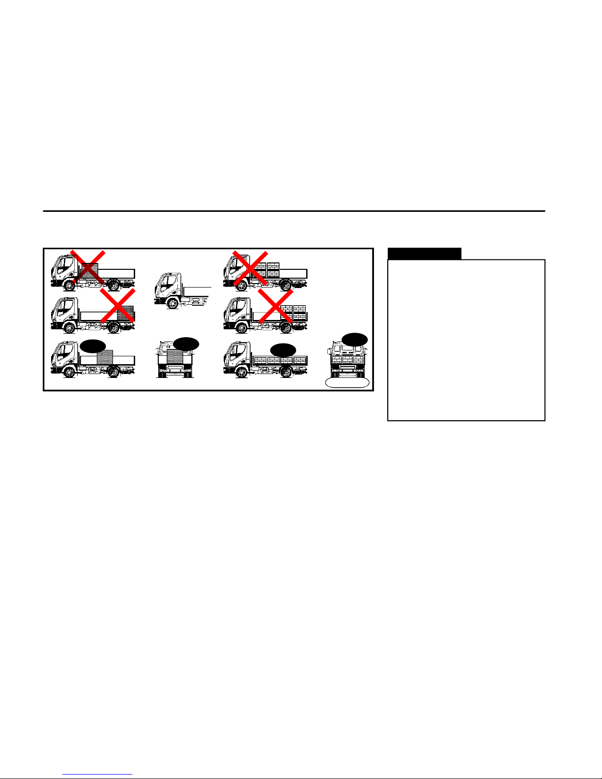
O P E R A T I N G I N S T R U C T I O N S
62
Transport of loads
During the load transport, it is necessary to abide by the below mentioned
instructions:
n Do not exceed the maximum allowable front axle load (see Chapter: Weights
and axle loads in the section Tech. Data).
n Take care that the load is distributed
correctly on the load space of the vehicle:
- place the load to the centre of the
load space
- place the load evenly on the whole
load space
- keep a correct distribution of the weight
(1/3 to the front ax. and 2/3 to the rear ax.)
Loading the train combination towing vehicle with trailer
n For combinations with central axles
trailer (trailer with fixed towbar) it is
necessary to consider for calculateing
the total load of the towing vehicle a
vertical statica load coming from the
trailer, developing load strain onto the
coupling point (up to 10% of the total
trailer weight, max.1000kg). This additional load surcharges the rear axle
and simultaneously discharges the
front axle of the towing vehicle.
OK
OK
OK
OK
FN0721a
Warning!
n The towing combination load
must be equally distributed in such
a way, that the minimal front axle
load is at least 30% of the total
axle load of the towing vehicle and
at the same time the maximal
axle loads on all axles are not
exceeded.
n For unloaded towing vehicle is
allowed to tow only an unloaded
central axle trailer with fixed towbar. This guideline is however not
applicable for standard trailer with
steering bogie.
Page 63
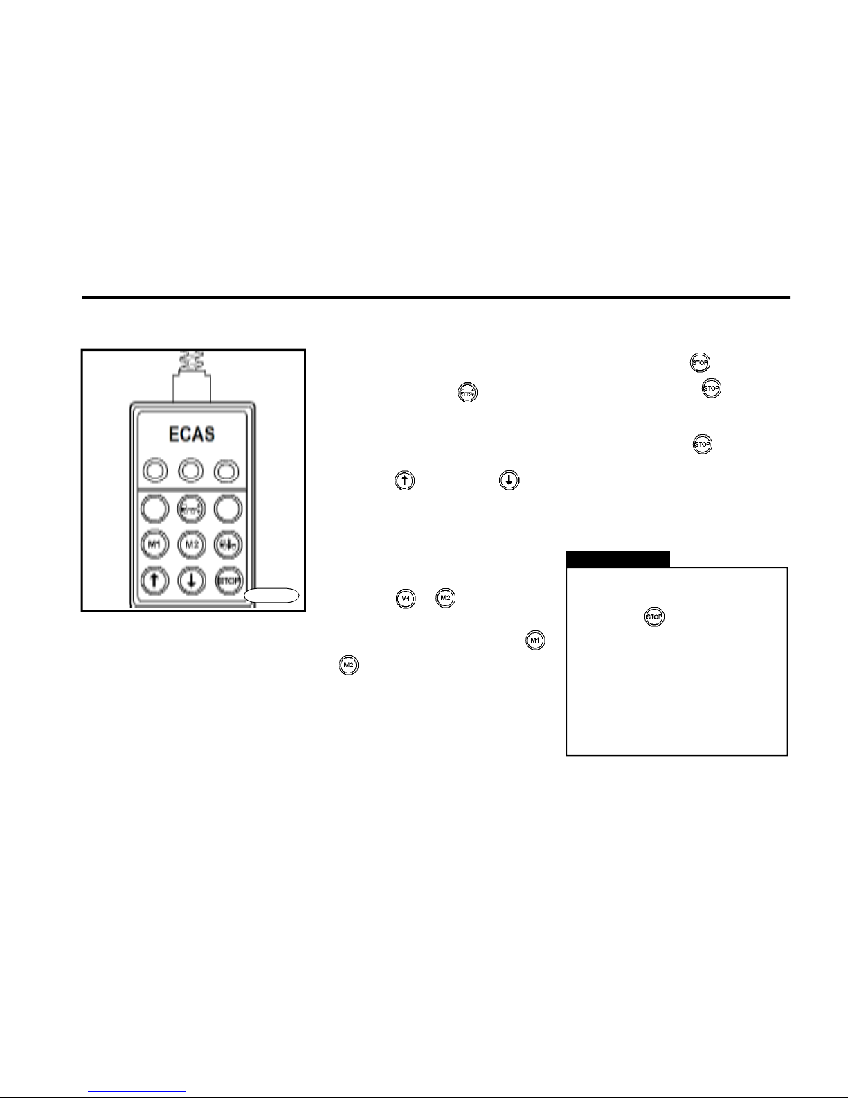
O P E R A T I N G I N S T R U C T I O N S
63
Electronic vehicle height adjustment (ECAS)*
n The pneumatic suspension allows
you to adjust the height of the vehicle tail
part, suitable for coupling/discoupling
the trailer or for loading/unloading the
vehicle at a ramp.
n The height can be adjusted also
while driving, however maximally up to
10 km/h speed.
n If the vehicle height is outside the
driving position (level), the height will
be automatically corrected after exceeding the speed 15 km/h.
Operating guidelines
n System "switch on"
By pushing the button the system
becomes active. Activated system is
indicated by the control light over the
button.
n Adjustment of desired height
By buttons or choosing the
height desired.
n Memory utilisation
Note: there are 2 memories for saving
two different heights.
To reach the height desired push the
button "STOP" and simultaneously
push button or . Desired height
is saved in the selected Memory.
Then in case you operate the button
or , the height saved in the selected
memory is automatically adjustedi. Different height can be adjusted in the
same way.
FN0134_b
n Button utilisation
By pushing the button the opera-
tion raising / lowering the pneumatic
suspension is immediately stopped.
By pushing the button while switch-
ing off the ignition the "Stand by" function is activated, which enables normal
handling of the pneumatic suspension
for 60 seconds (this is limited by air
pressure).
n In case of any danger the operation can be stopped by pushing
the button .
n Fix the rear axle to the vehicle
frame when raising the whole
vehicle in order to avoid so called
"sagging" of the rear axle.
If this instruction is not respected, the damage on pneumatic
suspension bellows may be the
consequence.
Warning!
Page 64
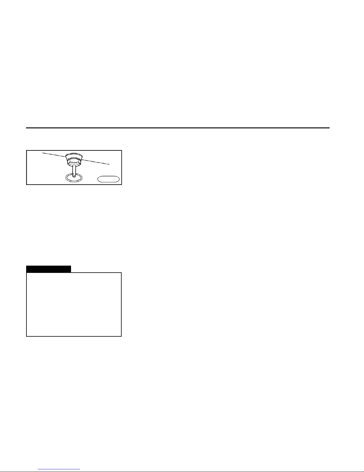
O P E R A T I N G I N S T R U C T I O N S
64
Draining the condensate
from air tanks
n In all air tanks of the pneumatic suspension and pneumatic brakes a water
condensate accumulates, which has
to be drained after every journey.
n When draining, a full operational air
pressure must be in the system. Water
condensate must be drained by swinging the handling levers of draining
valves placed at the bottom part of air
tanks.
FN0655
n In winter season and humid
weather the draining has to be
done several times a day..
n If the draining is not done regularly, as a consequence the vehicle safety can be compromised
and instruments can be damaged;
for such cases warranty is not
applicable.
Warning!
Page 65

O P E R A T I N G I N S T R U C T I O N S
65
n Secure the trailer rear wheels with
chocks.
n The front trailer axle must remain steering.
n Adjust the trailer draw bar into a
height of the trailer hitch.
n When engaging the reverse speed,
make sure that nobody is standing
between the trailer and vehicle.
n Make sure that the trailer is coupled
correctly.
n Attach the brake hoses coupling heads and plug connectors of electric conductors.
n Check the brake system and lights
for a correct function.
n Proceed very carefully when towing
a trailer and do not exceed the allowable load limits.
n When stopping during uphill or downhill driving, check the manual brake for
a good efficiency. It must hold the whole
vehicle combination in a gradient on
the spot.
Basic rules for the trailer coupling
Warning!
The pieces of information mentioned in this chapter are the basic
ones only. You should abide mainly
by the instructions given in the Operation Manual for the connected
vehicle.
Page 66

O P E R A T I N G I N S T R U C T I O N S
66
Page 67

O P E R A T I N G I N S T R U C T I O N S
67
n Clamps of all electrical consumers
of the vehicle must be connected correctly and their polarity must not be
mutually exchanged.
n Always charge the batteries outside
the vehicle.
n With the engine running, do not switch
off the battery circuit breaker and do not
disconnect battery terminals.
n During handling the vehicle when
short-circuit could occur, remember to
switch off the battery circuit breaker.
n When you wash the vehicle, protect
starter, alternator, glowing regulator and
battery case against water to avoid
short-circuit.
n For reasons of safety, during vehicle
standstill (when parking in garage, etc.),
when leaving the vehicle or when you
find out any fault in the electrical equipment, switch the battery off.
n When the fire could occur, use the
battery circuit breaker to disconnect the
electrical equipment.
n When the engine is not running,
the battery is discharged by use of
electrical consumers.
n Interdiction of electric arc welding outside the dealer service network. In case of breach of this
interdiction damages on vehicle
electrical components wil be the
consequence.
Warning!
Electrical equipment
Page 68
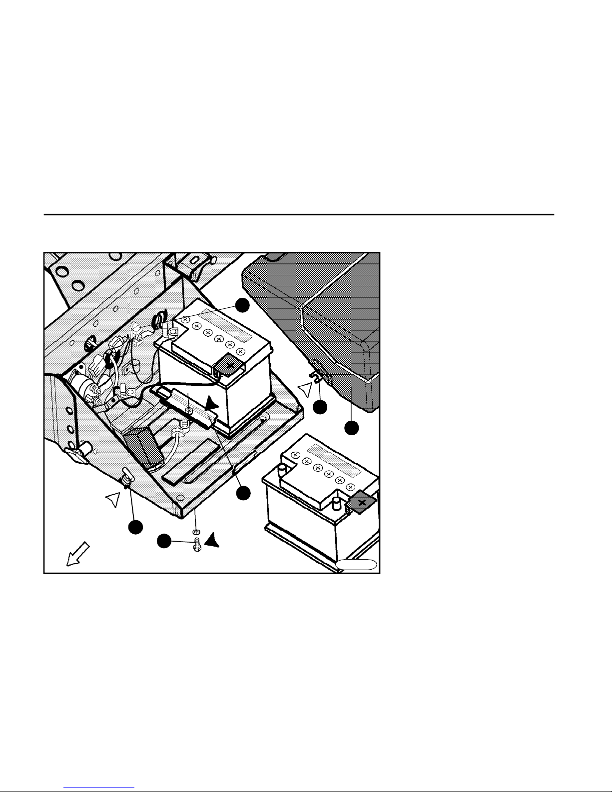
O P E R A T I N G I N S T R U C T I O N S
68
Location of battery
driving
direction
1 Plastic cover
2 Holder clip
3 Rubber holder
4 Profiled battery holder
5 Battery holder screw
6 Central ground point
1
2
6
3
5
4
FN0731cu
Page 69
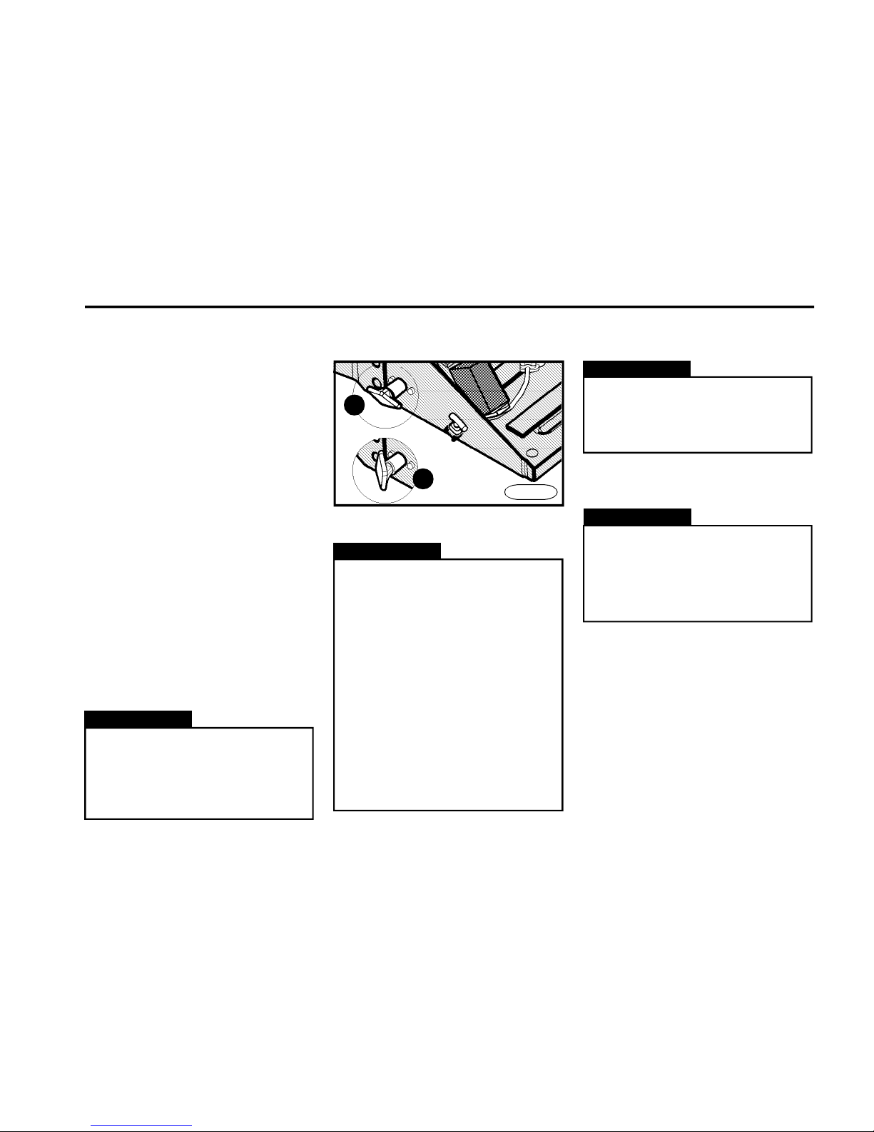
O P E R A T I N G I N S T R U C T I O N S
69
n Instructions for the operation and
maintenance are a part of the battery
warranty card delivered with the vehicle.
n Check the battery condition, electrolyte level and tightening-up of the ground
screw (item 7 on the previous page)
every six months.
n When disconnecting the battery
terminals, be sure to disconnect first
the negative ("–") terminal. Proceed with
care during removal of battery terminals
not to cause short-circuit between "+"
battery terminal and vehicle ground.
After cleaning and careful connection
of terminals connect the positive
terminal ("+") to the battery circuit
breaker again.
n Replace the discharged battery with
a battery of the same capacity, voltage,
ampere load and size.
n Charge up the battery always
outside the vehicle.
n The used battery must be
disposed of with regard to
environmental regulations.
Warning!
Battery circuit breaker
Alternator
With the engine running the
alternator terminals must not be
disconnected and the battery
circuit breaker must not be
switched off - the alternator must
not run without load.
Warning!
Battery
Acircuit breaker on / Bcircuit breaker off
Warning!
n Turn off the battery master switch
only 30 seconds after turning off the
ignition to allow data processing by
ECM (Eng. Cont. Mod.) and to allow
air to blow through the AdBlue injection sys. into the exhaust system
(noise from the area of AdBlue tank
may be heard). If the instruction as
above is not followed a fault may be
reported by warning lamps or the
SCR sys. and/or damage of the SCR
sys. may be caused due to insufficient removal of AdBlue residues
(possible crystallization or freezing) and thus causing blockage of it.
A
B
FN0741
Never shut the engine off by the
battery circuit breaker - this could
damage the electrical equipment
and alternator.
Warning!
Page 70
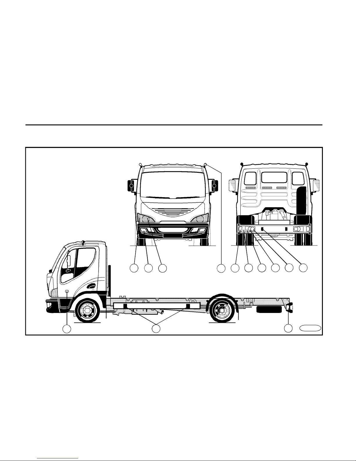
O P E R A T I N G I N S T R U C T I O N S
70
1
4 3
Headlamps and lights - location
1 Front headlamps
2 Front auxiliary side marker lamps
3 Front fog lamps
4 Turn signals
5 Stop lights
6 Rear side marker lights
7 Reverse lights
8 Tail fog lamps
9 License plate light
10Side positioning lamps
11Side turn signals
(If the vehicle is fitted with a superstructure
2,550mm wide, mount the side marker lamps
of the superstructure manufacturer.)
10
2
10
546
97
8
11
FN0750
Page 71

O P E R A T I N G I N S T R U C T I O N S
71
Cleaning agents
n As far as the cleaning agents or
other chemical vehicle-care products
are concerned, you should follow the
manufacturer´s directions when using
them both for the vehicle interior or
exterior.
n The non-suitable cleaning agents
may impair the value of vehicle components.
n You should not use the volatile
agents (acetone, diluents, gasoline),
cleaning agents (wash powders) and
bleaching or other aggressive agents
except for those recommended to remove spots from clothes.
n Take care that the ventilation is enough when working in interior (vapours of
some agents are harmful to health).
Vehicle care
Care of the vehicle interior
It is important to use correct cleaning
agents and procedures (see instructions mentioned on cleaning agents).
When not observing these instructions, hard removable spots may stay on
interior materials after cleaning.
Plastic parts
n Use wet rag to clean the plastic parts.
n After a rough cleaning by wet rag, you
can apply the agents recommended.
Seat belts
Clean them with a soap water solution.
Warning!
In case that the vehicle is fitted
with a superstructure and the tailgate covers the rear cluster lamps
in a tilted condition, the driver is
obliged to place a warning triangle
behind the vehicle under dec-reased visibility with the tailgate tilted
and standing on a road. The special label inside the cabin being
visible from the driver´s place reminds you of this obligation.
Warning!
n The seat belts should be kept
clean - dirt would affect the function of retractor.
n Before winding, the seat belts
must be perfectly dry.
n The seat belts must not be cleaned chemically.
Page 72

O P E R A T I N G I N S T R U C T I O N S
72
Warning!
Do not apply polishing and waxing
agents to plastic parts.
Warning!
Keep environmental regulations
when washing the vehicle.
Doors and windows seals
Apply rubber preserving agents to seals
of doors and windows from time to time
to increase their life.
Windows
n Use window cleaning agents.
n Use a plastic scraper to remove
snow in winter.
Care of the vehicle exterior
n Frequent washing and preserving
are a good protection of the vehicle
against negative influences of the environment.
n Regular care will contribute to maintain the value of your vehicle.
n It is important to use correct cleaning agents and procedures (see instructions mentioned on packages of
cleaning agents). When not observing
these instructions, hard removable
spots may stay on exterior surface
materials after cleaning.
Washing the vehicle
n The best way how to maintain the
paint in a good condition is to wash it
very often.
n Use the lukewarm or cold water to
wash the vehicle.
n Do not use hot water or do not wash
the vehicle in direct sunlight.
n First use plenty of water to wash off
the dirt thoroughly.
n After washing off the dirt, use a soft
sponge to clean the body from the roof
down using water and car-wash shampoo in ratio as mentioned on the packing. It is necessary to rinse the sponge
often during washing.
n Use plenty of water to rinse the vehicle off after washing (do not allow the
agents to dry on the body paint) and dry
it out with a chamois.
Waxing and polishing
n When waxing and polishing the vehicle regularly, you will obtain a good
shine and easier maintenance during
the next washing.
n Apply wax to a clean and dry body.
Damage to the body paint
Correct each damage to paint promptly
not to allow a rapid corrosion of the bare
metal. Entrust the work to a specialized
workshop.
Page 73
73
T R O U B L E S H O O T I N G
Engine
1. Starter does not crank the engine or
cranks slowly
A) Fault: Battery circuit breaker is off
Remedy: Switch the battery circuit breaker on
B) Fault: Engaged gear
Remedy: Move the gearshift lever to the neutral position.
C) Fault: Blown fuse
Remedy: Replace the fuse. If the new fuse blows
immediately again, have the vehicle checked at the
authorized service station
D) Fault: Charged battery
Remedy: Charge the battery according to instructions
mentioned in the battery warranty card delivered with
the vehicle
E) Fault: Faulty electric wiring
Remedy:
- Check and clean battery outlets and terminals
- Check and/or clean connections from battery to engine
- Check the cables connection of starter and/or tighten
F) Fault: Faulty neutral switch
Remedy: Contact and have it repaired at the auth. serv. station
G) Fault: Faulty starter
Remedy: Contact and have it repaired at an authorized
service station
2. Starter cranks the engine but the
engine cannot be started
A) Fault: No fuel in tank
Remedy: Fill the fuel and bleed the fuel system
3. Engine starts but will not keep running
A) Fault: Too low idle run speed
Remedy: Contact and have it repaired at an authorized
service station
B) Fault: Faulty fuel inlet
Remedy: Contact and have it repaired at an authorized
service station
C) Fault: Clogged fuel filter cartridge
Remedy: Contact and have it repaired at an authorized
service station
D) Fault: Air penetrates into the fuel system
Remedy: Contact and have it repaired at an authorized
service station
Page 74

74
T R O U B L E S H O O T I N G
Engine
4. Engine will not reach the rated output
A) Fault: Fuel filter has been clogged with dirt
Remedy: Contact and have it repaired at an authorized
service station
B) Fault: Wrong function of injection system
Remedy: Contact and have it repaired at an authorized
service station
C) Fault: AdBlue tank empty
Remedy: AdBlue tank re-filling
5. Engine is knocking
Remedy: Contact and have it repaired at an authorized
service station
6. Engine smokes excessively
A) Fault: Faulty or wrong adjusted injection unit or
fuel injectors
Remedy: Contact and have it repaired at an authorized
service station
B) Fault: Faulty turbocharger
Remedy: Contact and have it repaired at an authorized
service station
7. Engine overheats
A) Fault: Insufficient coolant level
Remedy: Check the cooling circuit for leaks, repair the
fault and add the fluid
B) Fault: Insufficient function of cooler
Remedy: Clean the cooler surface
C) Fault: Faulty thermostat
Remedy: Contact and have it repaired at an authorized
service station
D) Fault: Faulty function of the fan visco-coupling
Remedy: Contact and have it repaired at an authorized
service station
CAUTION:
If the cooling indicator light comes on, it is necessary
to stop the vehicle as soon as possible and to cool
down the engine by enhanced engine speed (1,200 ÷
1,500 rpm).
In any case do not shut the engine off after the cooling
indicator light comes on.
Page 75
75
T R O U B L E S H O O T I N G
8. "Engine - stop" indicator light ON
Fault: Serious engine defect (it may be probably the
coolant temperature, charge air temperature or oil
pressure)
Remedy: Stop the vehicle and shut the engine off.
Carry out the diagnostic test (the diagnostic procedure is
mentioned on the following page). If the light code lights
up during this test, there is a serious defect in the engine
and it is necessary to contact the authorized service
station. It is strictly prohibited to continue to drive the
vehicle. However, when the indicator lights "engine - stop"
and "engine - warning" light together permanently during
the diagnostic test, you can continue to drive the vehicle.
9. Indicator light "engine - warning" is ON
Fault: Fault in the engine system or in the engine
component and/or the AdBlue fluid volume drop in the
tank below 3 l
Remedy: Add the AdBlue fluid to tank. If the indicator
light still remains ON, you can continue to operate the
vehicle, but when you reach ther nearest service
station, have the fault repaired - this situation is not
considered to be a state of emergency.
Engine
10. Indicator light
"engine - warning" flashes
Fault: If the indicator light flashes for about 30
seconds when the ignition is in the position "ON". It
reminds you of carrying our the necessary service
job (e.g. the engine oil change) or it indicates the
presence of water in fuel.
Remedy: Drain the fuel filter according to Chapter
"Draining the fuel filter".
If the indicator light is still ON, it is necessary to contact
the authorized service station.
Note: After the oil has been changed do not forget to
store this action into the engine ECM - have it carried
out by the authorized repair shop.
11. Indicator light
" SCR system malfunction" is ON
Fault: The tank of AdBlue is empty
Remedy: The vehicle may be still operated, but when
you reach ther nearest service station, have the fault
repaired - this situation is not considered to be a state
of emergency.
Page 76
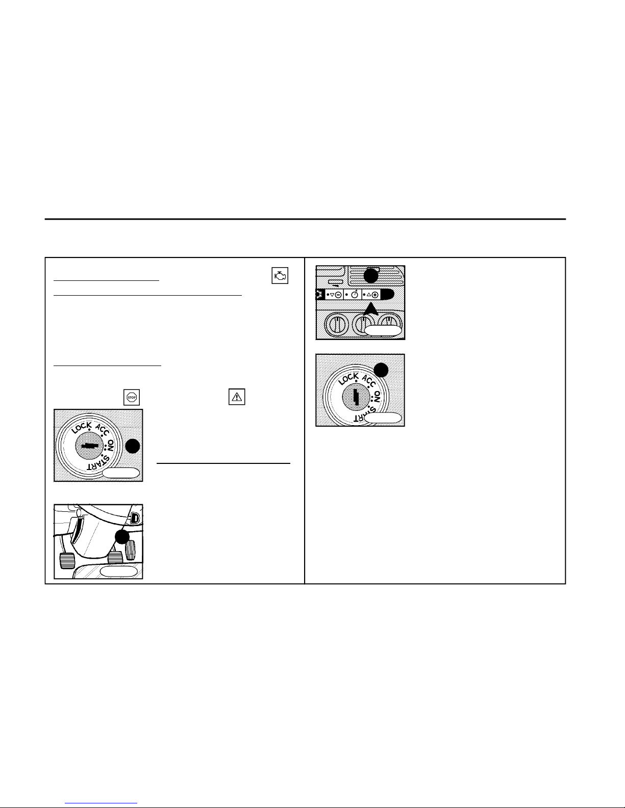
76
T R O U B L E S H O O T I N G
FN0751
1
Which of two indicator lamps is
on determines the kind of defect
(three- to four-digit fault code).
How to start the diagnostic test:
1) The ignition key must be in
position "ON" (item 1).
2) Depress three times the accelerator pedal and release it
(item 2) -
3) The orange indicator light
"engine - warning" will begin
lighting and when it goes out,
the red indicator light "engine stop" will start blinking to show
FN0757
4
12. Indicator light
"SCR system malfunction" flashes
Fault: Fluid AdBlue level drop below 10 liters
Remedy: Add the AdBlue fluid level to tank during the
next Diesel refuelling
13. D iagnostic test
Fault: The indicator lights
"engine - stop" "engine - warning" are ON
the fault code.
The fault code blinking repeats
itself continuously. It is necessary to put down the fault code
number. To detect other faults, it
is necessary to push the cruise
control switch (item 3) marked
"+" and the procedure of fault
code blinking will begin to repeat
itself - either the same fault code
appears (if there is no other fault
code) or another fault code displays (put it down) and by repeated pushing the cruise control
switch "+" further blinking of the
fault code will be activated - go on
in that way until the first fault code
appears again.
On termination of the diagnostic
test, move the ignition key (item 4
to position "ACC" and wait 30
seconds.
2
FN0752r
FN0754r
3
Page 77
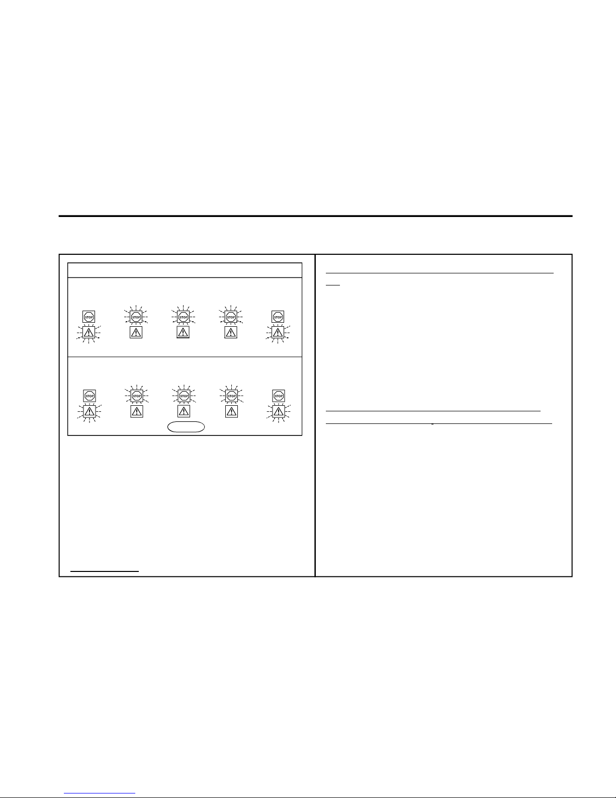
77
T R O U B L E S H O O T I N G
Engine
it comes on
it goes out
it goes out
Example of fault codes
P=pause Fault code 115:
1 it lights
1x blinks 1 x blinks 5 x blinks
P P P P
Fault code 244:
1 it lights
2x blinks 4x blinks 4x blinks
P P P P
FN075 8
The indicator light "engine-stop" displays the fault code
number. The example of fault code determination is illustrated.
- after the orange indicator light "engine-warning" goes out
-1x the red light blinks
-pause 1-2 s
-1x the red light blinks
-pause 1-2 s
-5x the red light blinks
-pause 1-2 s
- the orange light come on again (end of fault code lighting)
fault code = 115
it comes on
Electrical equipment
1. The battery charging indicator light is
on
A) Fault: Fault in the charging circuit
Remedy: First check whether all cables of alternator,
accumulator batteries and battery circuit breaker are
tightened thoroughly and/or connected to respective
terminals. Check also whether connections including
the battery ground cable have not been corroded. If all
the above have been checked and found correct it is
necessary to go to an authorised repair shop.
2. The battery charging indicator light
does not come ON when the ignition is ON
Remedy: Contact and have it repaired at an authorized
service station
Page 78
78
T R O U B L E S H O O T I N G
Monoblock hydraulic power steering Brakes
3. The parking brake has been blocked,
the air pressure gauge of brake system
indicates the pressure below the minimum value, the vehicle cannot be put in
motion
Remedy: If even after several minutes of engine running the
operating air pressure in the system is not reached, release
the spring brake cylinders (see Chapter Parking brake) and
have the vehicle towed to the nearest repair shop.
4. The ABS indicator light is on
Remedy: The equipment is not OK, the vehicle is braked
without ABS function. Only the normal brake system is
functioning on the vehicle. In that case it is promptly
necessary to visit the authorized service station. Adapt the
driving to the situation.
5. The ASR indicator light is on
Remedy: The equipment is not OK, the ASR system is not
working. It is necessary to visit the authorized service
station.
Note: When the ASR system is out of function, the common
vehicle operation is not influenced.
6. Warning lamp is flashing "Air
suspension system failure*
/red warning lamp/
Repair: The pneumatic suspension system is out of
order.
If the situation allows that, it is possible to drive to the
nearest authorised workshop. The driver however has to
drive with maximum precaution with regard to existing
circumstances so that the road circulation safety or his
own personal sefaty are not endangered.
If the vehicle height is below the driving height (level),
continuation of the journey is inadmissible and Assistance
service has to be called in.
Page 79
79
T R O U B L E S H O O T I N G
3. The parking brake has been blocked,
the air pressure gauge of brake system
indicates the pressure below the minimum value, the vehicle cannot be put in
motion
Remedy: If even after several minutes of engine
running the operating air pressure in the system is not
reached, release the spring brake cylinders (see Chapter
Parking brake) and have the vehicle towed to the nearest
repair shop.
4. The ABS indicator light is on
Remedy: The equipment is not OK, the vehicle is braked
without ABS function. Only the normal brake system is
functioning on the vehicle. In that case it is promptly
necessary to visit the authorized service station. Adapt the
driving to the situation.
5. The ASR indicator light is on
Remedy: The equipment is not OK, the ASR system is not
working. It is necessary to visit the authorized service
station.
Note: When the ASR system is out of function, the common
vehicle operation is not influenced.
Page 80
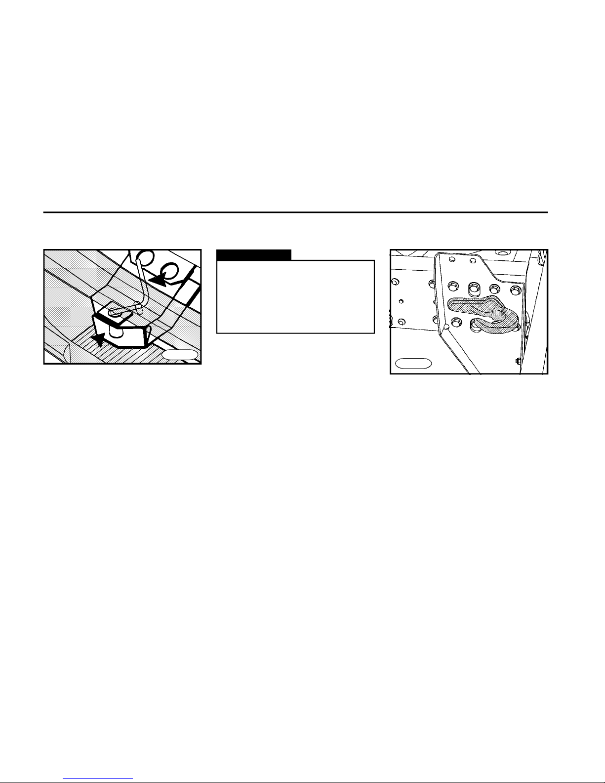
80
T R O U B L E S H O O T I N G
Towing
FN0770
FN0760
There is a special hook welded to the left
bracket on the rear bumper to hold a
rope in case of recovery.
n With the engine off, the power
steering and brake booster are out
of function.
n Use only the tow bar to tow the
vehicle; other connection is not
permitted.
Warning!
Disconnecting the propeller
shaft
n Secure the vehicle against motion.
n Dismount bolts fixing the propeller
shaft to the axle final drive housing
flange.
n Attach the propeller shaft to the vehicle frame in a suitable manner.
n After the vehicle towing and repair
have been accomplished, remount the
propeller shaft to the axle final drive
housing flange again; tighten the selflocking nuts to Mk = 60±10 Nm.
n Use the pin to attach the towing bar
in the middle part of the front bumper.
n When towing the vehicle with the
engine at standstill and no gear speed
shifted in gearbox, disconnect the propeller shaft not to damage the gearbox
due to insufficient lubrication and release the spring-loaded cylinder in accordance with Chapter "Parking brake".
n The ratio of the towed and towing
vehicles weights must be 1.4:1 at least.
Vehicle recovery
Page 81
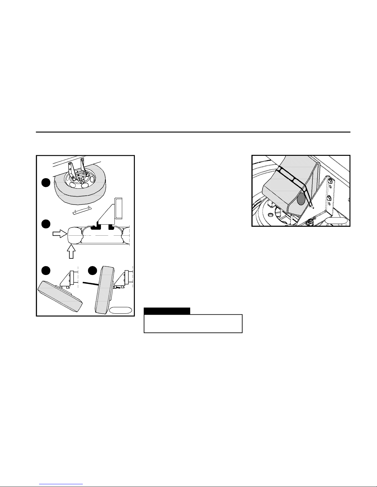
81
T R O U B L E S H O O T I N G
Spare wheel holder (L, E, S, G)
n Raise the wheel while holding the
tire (Fig. B) in point 1 and with the wheel
lifted, push in point 2 towards the centre
of the vehicle (the wheel will swing - see
Fig.C - danger of injury).
n Remove the wheel from holder.
Installation of spare wheel
n Use the assembling bar for the cabin
lifting to raise the wheel so that it
remains hanging in grooves of front
holder brackets (Fig.D).
n Swing the wheel into the horizontal
position towards you so that it rests on
the contact surface of the rear bracket
and simultaneously on contact surfaces of front brackets ahead of stop
lugs.
n Tighten the thrust plate from below
by two nuts and secure with the wire clip
at one of two bolts.
Removal of spare wheel
n Dismount the spring split pin and
two nuts to loosen the thrust plate
(Fig. A).
Wheel chock (L, E, S, G)
Warning!
Proceed with extreme care with
regard to the wheel weight.
FN0790
A
DC
B
21
1
FN0780
It is fitted above the holder of the spare
wheel.
Page 82
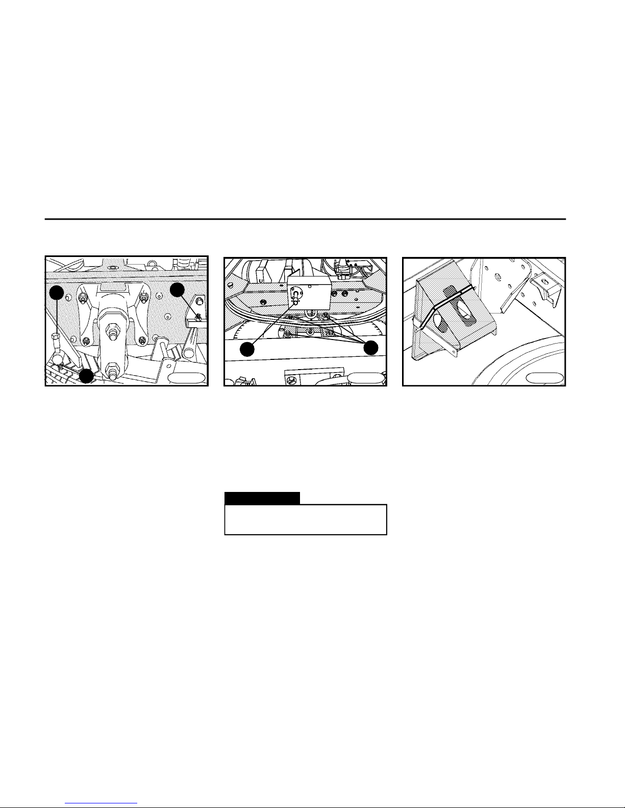
82
T R O U B L E S H O O T I N G
Spare wheel holder (K, N)
Removal of spare wheel
n Dismount bolt 1 c/w nut 2 and nut 3
on the LH and RH side of the spare
wheel hanger.
n Put the handle out of the vehicle
equipment onto a winch 4 and turn the
handle to lower the spare wheel c/w
hanger on ground.
n Dismount four bolts c/w nuts 5 and
remove the wheel from hanger.
Wheel chock (K, N)
5
Warning!
Proceed with extreme care with
regard to the wheel weight.
FN0820FN0801
4
Installation of spare wheel
n During installation first attach the
spare wheel by four bolts c/w nuts to the
hanger, use the winch to attract the
hanger c/w spare wheel to the frame
and secure the hanger with bolt 1 c/w
nut 2 and nut 3 on each side.
FN0800a
1
3
2
It is fitted on the rear bumper.
Page 83

83
T R O U B L E S H O O T I N G
Page 84
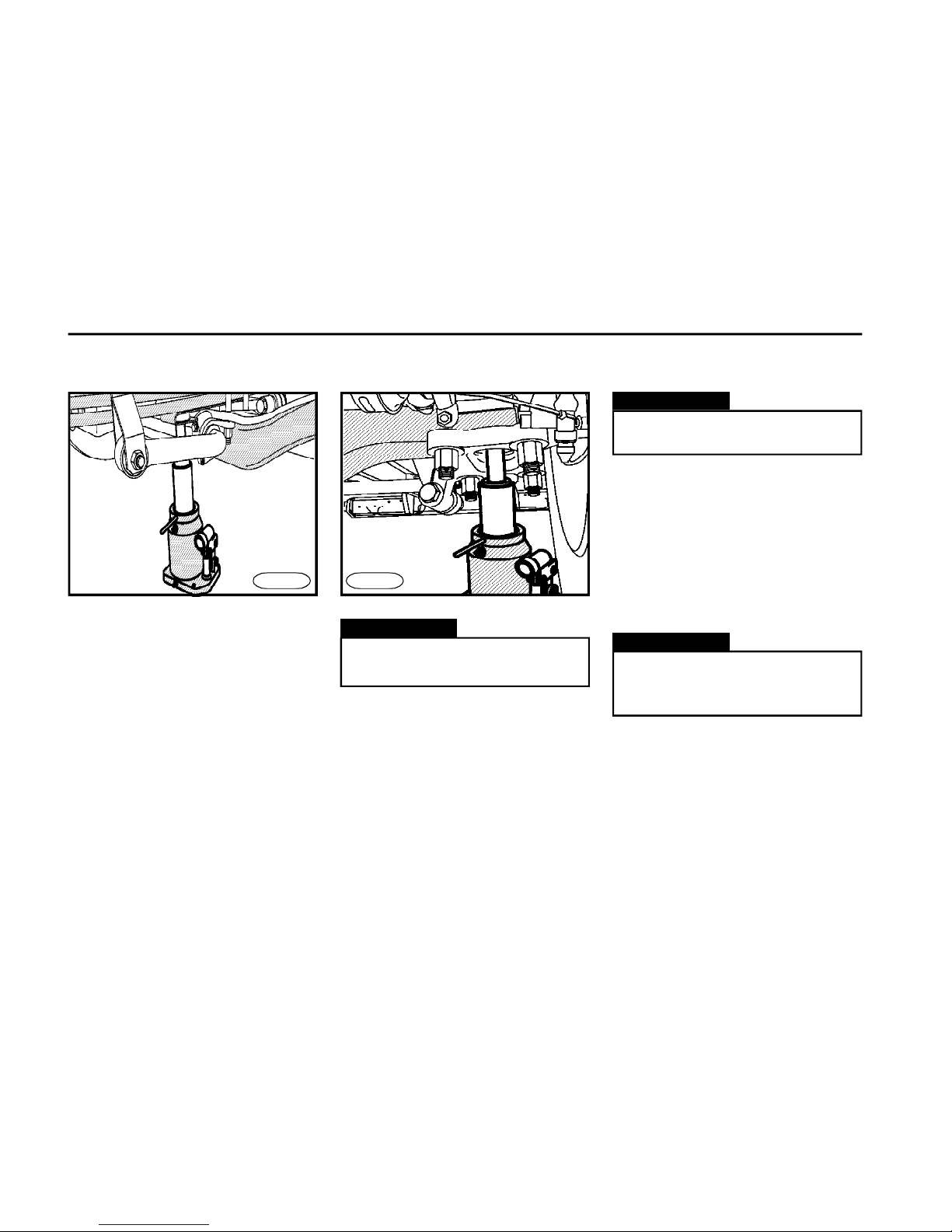
84
T R O U B L E S H O O T I N G
Changing the wheel
FN0830n
n When changing a wheel, the vehicle
must stand on level ground if possible.
n Secure the vehicle with the wheel
chock and set the parking brake.
n Remove the spare wheel from holder.
n Loosen the wheel nuts by a lug wrench
(from the vehicle equipment) by 1/2 turn.
n Location of jack:
- on the front axle, place the jack with its
head into a hole in the metal sheet
guide situated under the leaf spring
ahead of the axle (see the figure).
- on the rear axle, place the jack with its
head into a recess of the clamping
plate of the leaf spring shackle.
n Raise the wheel by several centimetres above the ground by moving the lever
(with the valve closed).
n Unscrew the wheel nuts, remove the
wheel and fit the spare wheel in place.
n The contact surfaces of disc and
wheel hub must be clean.
n Tighten the wheel nuts partially and
evenly.
FN0840n
Front axle
Rear axle
Warning!
The jack must stand firmly on the
firm subgrade.
Warning!
With the vehicle lifted, never start
the engine.
n Open the jack valve slowly and carefully lower the vehicle on ground.
n Tighten the wheel nuts completely
to:
D 60-100 370 ± 30 Nm (6 X M18)
D110-120 485 ± 35 Nm (8 X M20)
n Check tightness of wheel nuts after
covering 50 ÷ 100 km.
Warning!
Operating and transporting positions are shown on stickers placed
directly on the jack.
Page 85
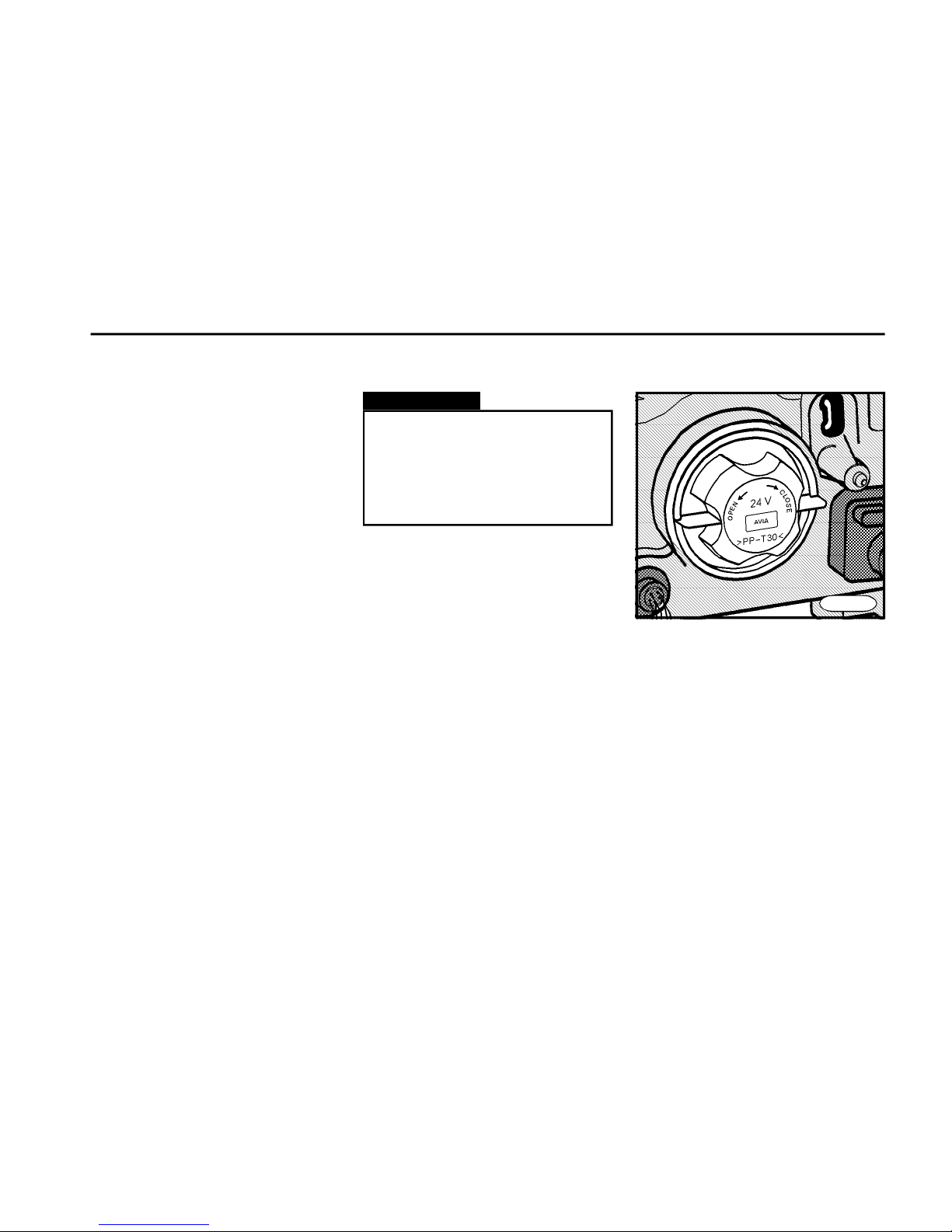
85
T R O U B L E S H O O T I N G
Replacing bulbs
n Prior to the bulb replacement, switch
off the respective light.
n Replace the defective bulbs with
bulbs of the same parametres (designation and parametres are mentioned
on the bulb).
n Do not touch the halogen bulb glass
with bare fingers - it would loose its
efficiency after switching on.
Main headlamp
n Tilt the cabin to replace the bulb.
n Slightly turn the cover plastic lid of
the headlamp counterclockwise and
remove.
Warning!
n Only the authorized service station may adjust the main headlamps.
n A new bulb must correspond to
the specified bulb by its type and
output.
FN0850
Page 86
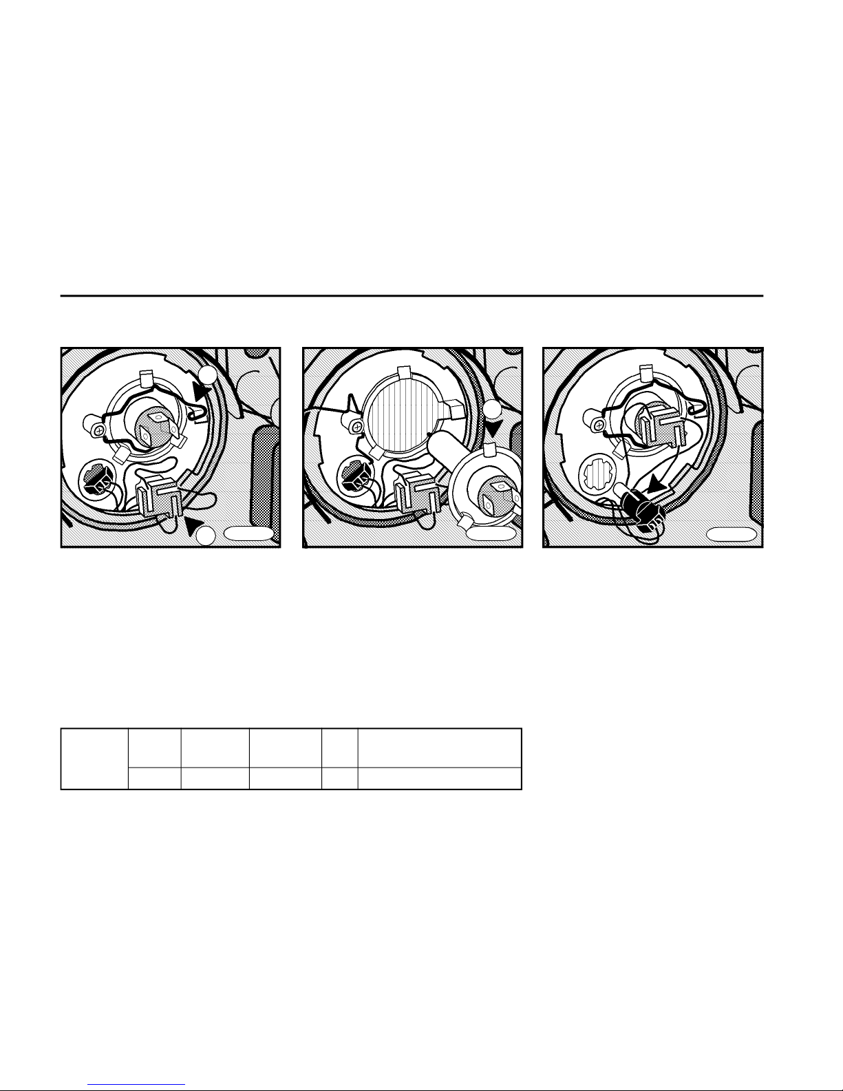
86
T R O U B L E S H O O T I N G
FN0870
Front side marker lights
n Remove the socket out of the
headlamp.
n Take the bulb out of socket.
n Insert a new bulb and proceed in a
reverse manner.
FN0880
Front part H4 24 V 70/75 W 2 headlamp - low and high
beam
24 V 5 W 2 side marker light
Low and high beam
n Unplug the connector (item 1)
from the bulb.
n Unhook and fold the flexible wire
holder (item 2).
n Remove the faulty bulb and fit a new
bulb - lugs (item 3) on the bulb base
must engage into recesses of the
headlamp.
n Installation is reverse of removal.
3
FN0860
1
2
Page 87
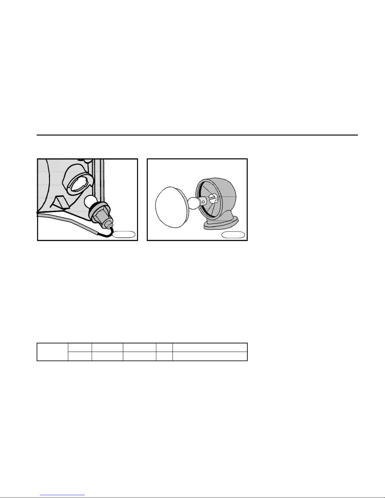
87
T R O U B L E S H O O T I N G
FN0890
FN0900
Front 24 V 21 W 2 turn signals
part 24 V 5 W 2 auxiliary side positioning lights
Front turn signals
n To make a faulty bulb better accessible, open the cabin door.
n Turn the plastic socket of the bulb
counterclockwise and pull it out of the
light housing.
n Push the faulty bulb into socket, twist
counterclockwise and remove.
n Fit a new bulb, push it and turn clockwise.
n Install the bulb socket into a light
housing and turn clockwise as far as it
goes.
Front auxiliary side positioning
lights
n Use a screwdriver to remove cover
from the light housing.
n Push the faulty bulb into socket, twist
counterclockwise and remove.
n Fit a new bulb, push it and turn
clockwise.
n Install cover and push it in place.
Page 88
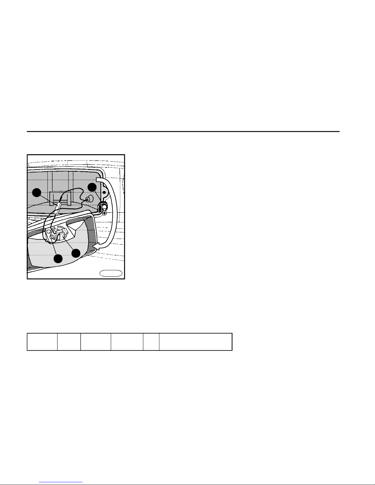
88
T R O U B L E S H O O T I N G
Front H3 24 V 70 W 2 fog lamps
part
Front fog lamps
n Unscrew plastic clips (item 1) from
the fog lamp housing.
n Remove the housing.
n Bend the ground connector
perpendicularly (item 2).
n Disconnect the cable (item 3) by
pulling it out.
n Unhook and fold the flexible wire
holder (item 4).
n Remove the defective bulb and insert
a new one (slots on the bulb socket
must engage into lugs in the fog lamp
housing).
n To reinstall, reverse the above
procedure (do not forget to bend the
ground connector back into the initial
position).
n The designation TOP must be
directed up.
n Have the headlamps adjusted at the
authorized service station.
2
3
1
4
FN0910
Page 89
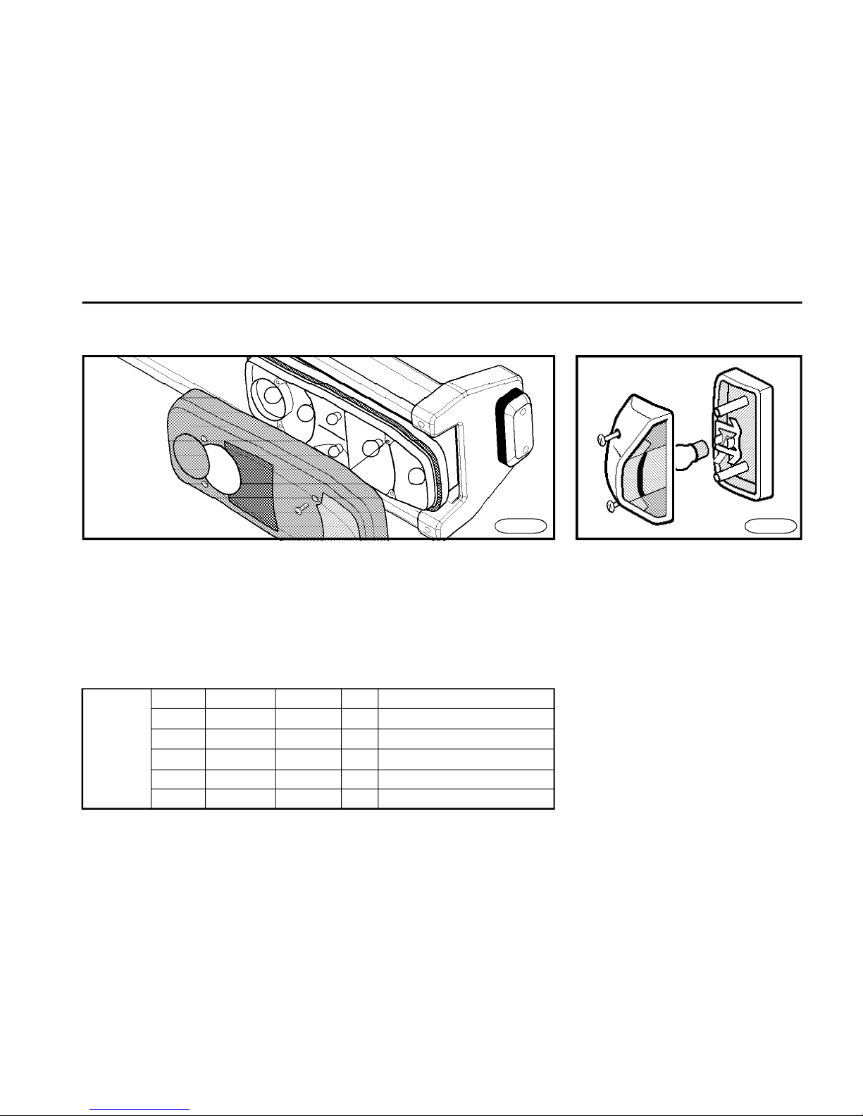
89
T R O U B L E S H O O T I N G
Rear 24 V 10 W 2 red side marker light
part 24 V 21 W 2 red stop light
24 V 21 W 2 orange turn signal
24 V 21 W 2 red fog lamp
24 V 21 W 2 white reverse light
24 V 10 W 2 license plate lights
FN0920
n Fit a new bulb, push it and turn
clockwise.
n Install and screw the cover. Tighten
the cover carefully as this may crack.
Rear cluster lamps
n Unscrew the lamp cover.
n Push the defective bulb into socket,
twist counterclockwise and remove.
License plate light
n Unscrew the lamp cover.
n Push the defective bulb into socket,
twist counterclockwise and remove.
n Fit a new bulb, push it and turn
clockwise.
n Install and screw the cover. Tighten
the cover carefully as this may crack.
FN0921
Page 90
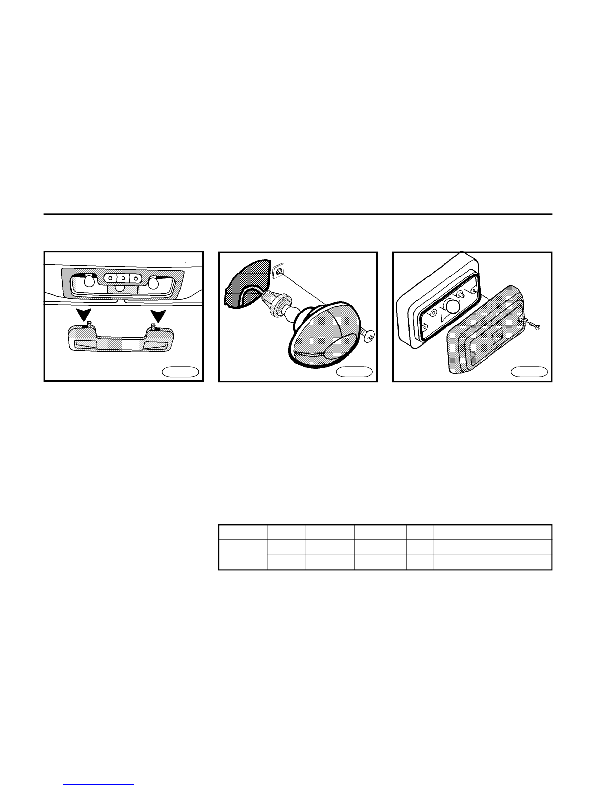
90
T R O U B L E S H O O T I N G
FN0950
Side turn signals
n Unscrew the lamp.
n Push the faulty bulb into socket, twist
counterclockwise and remove.
n Fit a new bulb, push it and turn
clockwise.
n Install the lamp spring clip in the
front part and screw. Tighten it carefully
as this may crack.
FN0940
Interior 24 V 12 W 3 dome light
Side 24 V 21 W 2 side turn signals
part 24 V 4 W 6 side positioning lights
Side positioning lights
n Unscrew the light cover.
n Push the defective bulb into socket,
twist counterclockwise and remove.
n Fit a new bulb, push it and turn
clockwise.
n Install and screw the cover. Tighten
the cover carefully as this may crack.
FN0930
Dome light
n Use a small screwdriver to pull cover
out of the light housing (you can see two
slots to insert the screwdriver in the
cover).
n Push the faulty bulb into socket, twist
counterclockwise and remove.
n Fit a new bulb, push it and turn
clockwise.
n Carefully install cover and push it in
place.
Page 91

91
T R O U B L E S H O O T I N G
Fuse box
Fuses
F1 10A speedometer, tachograph, clock
F2 10A brake lamps, instrument cluster
F3 10A indicator lights
F4 10A reverse lamps
F5 10A cab and cont lamps
*
F6 10A horn
F7 10A wipers
F8 25A heated mirrors
F9 25A blower motor
F10 25A air condition
*
F11 25A power windows
*
F12 10A differential lock / PTO / clock display
F13 10A engine control unit-tell tale
F14 10A central door locking
*,
cigarette lighter
F15 25A converter 24V/12V
F16 10A instrument cluster, speedometer, tachograph
F17 10A radio
F18 10A plug EURO 12V
F19 10A LH position lamps, RH outl. lamps,
instrument cluster illumination
F20 10A RH pos. lamps, LH outl. lamps,
switches illumination
F21 10A LH low beam
F22 10A RH low beam RH, headlamp level motor
F23 10A LH high beam
F24 10A RH high beam
F25 10A LH front fog lamp
*
F26 10A RH front fog lamp
*
F27 10A rear fog lamp
F28 10A engine starter
F29 10A fuel heating
F30 10A air heating
F31 30A engine control unit
F32 20A SCR dosing unit
F33 5A engine control unit (ECM)
F34 5A SCR dosing unit
F35 10A ABS control unit
F36 10A ABS control unit
F37 10A ABS control unit - towed vehicle
F38 10A ABS control unit - towed vehicle
F39 25A power for towed vehicle
F40 10A trailer indicators
F41 20A sensor NOx
F42 5A airsuspension - control unit
F0 80A heating of air sucked in (in the battery box)
Page 92
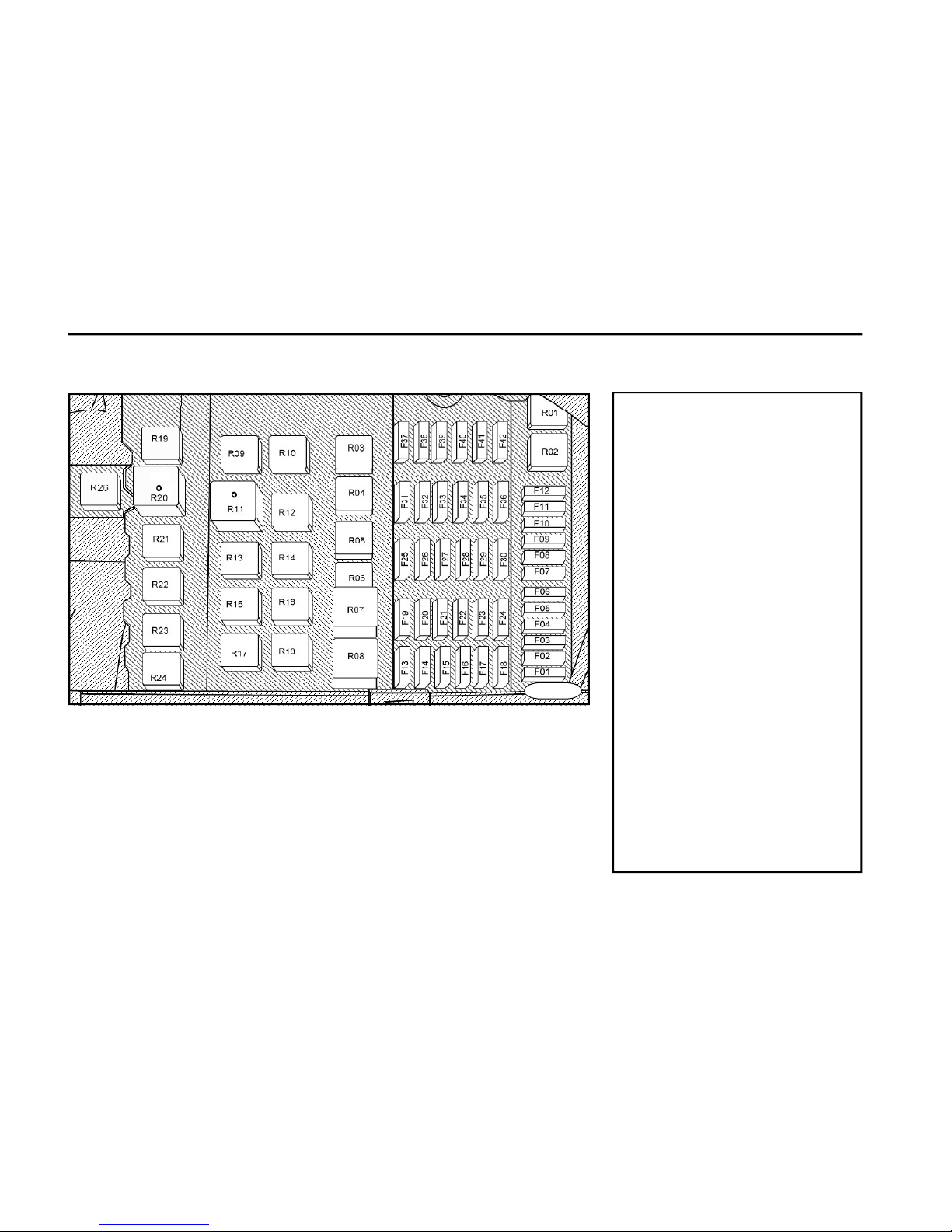
92
T R O U B L E S H O O T I N G
Relays
R01relay IGN 2
R02relay IGN 1
R03side light relay
R04low beam relay
R05high beam relay
R06intermittent wire relay
R07rear fog control module
R08front fog relay*
R09break lights relay
R10stop lamp monitor
R11turn signal relay
R12hazard relay 1
R13wiper activate relay 1
R14wiper activate relay 2
R15power windows relay 1*
R16power windows relay 2*
R17power windows relay 3*
R18power windows relay 4*
R19air condition relay*
R20heated mirror timer
R21relay "start"
R22relay "starter lockout"
R23ground relay
R24heated fuel relay
R26trailer indicators*
Replacing a fuse
n The fuse box is situated under the
glove box in the instrument board.
n Fuses are accessible after removal
of the glove box bottom which wil be
released by turning two rotary holders
(sense of turning is illustrated on the
cover).
n The individual electric circuits are
secured by fuses.
n The blown fuse can be recognized
by the burnt metal strip.
n Switch off the battery circuit breaker
during the fuse replacement.
n A new fuse must have the same
ampere value.
n It is necessary to keep spare fuses
on hand in vehicle.
FN0972
Page 93
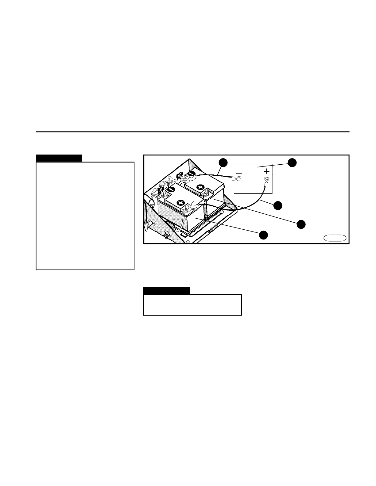
93
T R O U B L E S H O O T I N G
Warning!
n Replace the blown fuse with a
fuse of the same ampere value. Do
not use a fuse of higher amperage
because this could cause damage
the electrical part or even cause a
fire.
n If the fuse blows repeatedly after
switching on the respective electrical consumer, it is necessary to
contact and have the vehicle repaired at the authorized service station.
n Never repair the blown fuses.
n Do not use a screwdriver or other
metal object to remove the fuse.
n The vehicle with a discharged battery
may be started only by connecting it to
the battery of some other vehicle with
the same nominal voltage.
n Only approved jumper cables of
sufficient cross section may be used.
n Do not use cables with insulated
clamps only.
Warning!
The battery of the other vehicle must
have the nominal voltage of 24V.
n When starting, the engine of the
vehicle, whose battery is used to start,
must run.
Connecting procedure
1.Connect one clamp of "+" cable
(item 1) to positive terminal of the front
discharged battery (item 3).
2.Connect clamp on opposite end of
the same cable to positive terminal of
24V booster battery (item 5).
3.Connect clamp of "-" cable (item 2) to
negative terminal of 24V booster battery
(item 5).
Use of jumper cables to start the engine
FN0991
4
3
2
24V
5
1
Page 94

94
T R O U B L E S H O O T I N G
4.Firmly connect clamp on opposite
end of the same cable to "-" terminal of
the rear discharged battery (item 4).
5.The engine of the vehicle, whose
battery is used to start the other vehicle,
must run all the time.
Starting the engine
n Start the engine in accordance with
Chapter Starting the engine.
n After the engine starts to run, remove
jumper cables in reverse order.
n When using the jumper cables
to start the vehicle, the auto radio
must be turned off because this
may be damaged.
n Non-insulated parts of cable
clamps must not touch each other.
The jumper cable connected to the
positive terminal of the battery must
not come in contact with the vehicle ground because this could lead
to short circuit.
Warning!
Page 95

95
T E C H N I C A L D A T A
Engine
n
Diesel
n
turbocharged
n
with charge-air
n
OHV, four-strokenfour-cylinder,
n
water
with direct injection by one turbocharger cooling in-line cooled
Engine type designation
CUMMINS ISBe4 160 ISBe4 185
Number of cylinders / valves 4 / 16 4 / 16
Cylinders bore 104 mm 104 mm
Pistons stroke 132 mm 132 mm
Displacement 4,500 cm
3
4,500 cm
3
Compression ratio 17.3 17.3
Maximum output 117 kW / 2,500 rpm 136 kW / 2,500 rpm
Maximum torque 602 Nm / 1,200 ÷ 1,600 rpm 700 Nm / 1,200 ÷ 1,600 rpm
Injection system CommonRail Bosch; CommonRail Bosch;
electronic control unit electronic control unit
Page 96

96
T E C H N I C A L D A T A
Propeller shaft
n the version "K" has the one-shaft
arrangement with two universal joints
n versions N, L, E with two-shaft arrangement and three cross-shaped joints
with one intermediate bearing and sliding splined adaptor
n versions S,G with three-shaft arrangement and four cross-shaped joints
with two intermediate bearings and
sliding splined adaptor
Rear axle
n driving, banjo-type rigid axle
n axle final drive with single hypoid
gearing and bevel differential
n mechanical differential lock
n parabolic spring suspension with
stabilizer bar /non-existent in the version with pneumatic suspension/, or
pneumatic suspension.
n fluid shock absorbers with lower stop
n rubber upper stop for the version
with pneumatic suspension in the bel-
Engine cooling system
n fluid
n overpressure type with the forced
coolant circulation by means of the
centrifugal pump
n cooling circuit is fitted with two-flap
thermostat and expansion tank
Air filter
dry filter cartridge
Clutch
n dry
n one-disc
n with asbestos-free lining
n with mesh damper
n hydraulically controlled, with air boos-
ter
Gearbox
n mechanical
n with layshaft gear
n with gears in constant mesh
n synchronized
n gearshift lever control on floor
n gearbox allows to mount the power
take-off drive with pump, outlet shaft or
flange
Undercarriage
low.
n hypoid gears:
3,31 - 5,13
Front axle
n rigid, with forged axle casing
n parabolic spring suspension with
stabilizer bar, liquid shock absorbers
with lower stop
Page 97

97
T E C H N I C A L D A T A
Steering
n monoblock hydraulic power steering
n gear ratio from 14 to 16.6 - changeable during turning the steering wheel
between full locks
n split steering shaft c/w longitudinally
splined cardan joints
Frame
n ladder-type
n cold riveted
n screwed
n brackets or clips to attach chassis
groups or components are riveted or
screwed to the frame
n holes for brackets ready to attach
superstructures or directly riveted
brackets on frame longitudinal beams
n towing hook for the vehicle recovery
situated on the rear bumper bracket
Parking brake system
n parking braking secured by springloaded brake
n controlled by the manual brake valve
situated near to driver behind the gearshift lever
n the air pressure drop in the chamber
of spring-loaded cylinders to the value,
at which the spring-loaded brake is
activated, is indicated to a driver by the
respective indicator light.
Service brake system
n dual circuit
n pneumatic
n with brake pressure control of the
rear axle wheels (adjusted values of
the load sensing valve are stated on the
plate placed on the front door frame)
n TT system of brake circuits connection
n Anti-blocking Brake System (ABS)
as standard
Brake system
n disc brakes with rigid yoke on both
axles
n the brake system completed with
the parking brake equipment on the
rear axle
n two pressure gauges on the instrument board indicate the air pressures
in the brake system
Emergency brake
the emergency braking is secured by
one non-defective brake circuit
Page 98
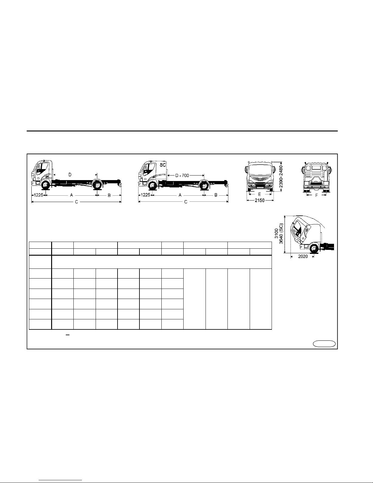
98
T E C H N I C A L D A T A
Dimensions of chassis c/w cabin
FN1001
A B C D E F
Version
60-120 60-100 110-120 60-100 110-120 60-120 60-100 110-120 60-100 110-120
Axle
base
( mm )
K* 2950* 1415* - 5590* - 2280*
1849 1845 1736 1740
N
3400 1415 1365 6040 5990 2730
L 3900 1670 1620 6795 6745 3230
E 4500 2070 2020 7795 7745 3830
S
5100 2470 2420 8795 8745 4430
G* 5600** - 2520** - 9345** 4930**
The tolerance + 1 %, holds for the dimensions if not stated otherwise.
*wheelbase “K” only for versions D60 – D90
**wheelbase “G” only for versions D110 – D120
Page 99
99
T E C H N I C A L D A T A
Weights and axle loads
Vehicle type D 60/65/70/75/80/85/90/100/110/120
Vehicle version K N L E S G
kg
Curb weight chassis + cabin
D60-75
3250 3300 3350 3400 3450 -
D80 3270 3310 3360 3410 3460 -
D85-90
3320 3370 3420 3470 3510 -
D100
- 3390 3440 3490 3530 -
D110-120
- 3510 3560 3610 3660 3720
Portion of the chassis c/w cab service
weight to front axle
D60-75
2090 2130 2170 2210 2250 -
D80
2110 2150 2190 2230 2270 -
D85-90 2110 2150 2190 2230 2270 -
D100
- 2160 2200 2240 2280 -
D110-120 - 2230 2270 2310 2350 2390
Portion of the chassis c/w cab service
weight to rear axle
D60-75
1160 1170 1180 1190 1200 -
D80 1160 1160 1170 1180 1190 -
D85-90
1210 1220 1230 1240 1240 -
D100
- 1230 1240 1250 1250 -
D110-120
- 1280 1290 1300 1310 1330
Carrying capacity of chassis + cabin
(c/w crew)
D60-75
2740
-
4240
2690
-
4190
2640
-
4140
2590
-
4090
2540
-
4040
-
D80
4720 4680 4630 4580 4530 -
D85-90
5170-
5680
5120-
5530
5070-
5580
5020-
5530
4980-
5490
-
D100
- 6600 6550 6500 6460 -
D110-120
-
7480-
8480
7430-
8430
7380-
8380
7330-
8330
7270-
8270
The table is continued on the next page
Page 100
100
T E C H N I C A L D A T A
Weights and axle loads
Vehicle type D 60/65/70/75/80/85/90/100/110/120
Vehicle version K N L E S G
kg
Max.vehicle overall weight1
D60 5990
D65 6490
D70 6990
D75
7490
D80 7990
D85 8490
D90 9000
D100 9990
D110
10990
D120 11990
The maximum allowable front axle load
D60-90 3400
D100
3500
D110 4000
D120 4200
The maximum allowable rear axle load
D60 4100
D65 4450
D70 4800
D75-80 5200
D85 5800
D90 6200
D100
6600
D110 7400
D120 8200
The table is continued on the next page
 Loading...