

NE-2000 Smoke Detector
INSTALLATION INSTRUCTIONS
Description
The NE-2000 is an Ionization smoke detector operating on 12-28V DC supply. This professional smoke
detector is applicable at both Fire and Alarm systems.
Installation Instructions
l Before wiring the smoke detector, verify the wiring terminals sign
l When using a non -EasyLoader panel verify compatibility
Step One: Mounting
Remove the smoke base by turning the base, attach to ceiling with two screws, and enter the
wires via the central round hole.
Step Two: Wiring
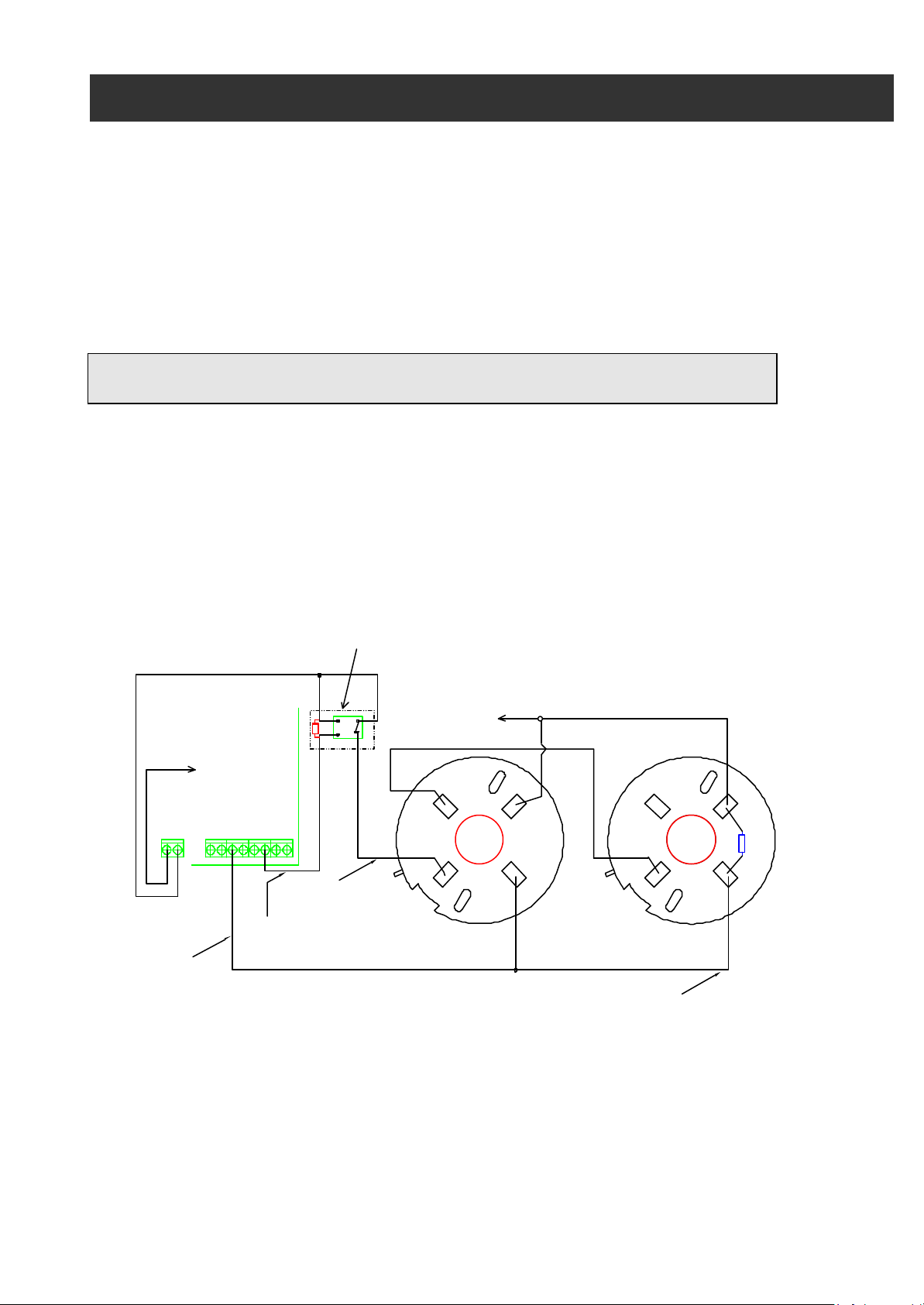
The detector drives -V (negative voltage) during alarm at the tag marked as -R. +E is the positive
DC supply IN, +0 is positive DC OUT to next detector. The (-) tag is the negative DC supply.
It’s recommended to wire the positive DC via the IN (+E) and OUT (+0) terminals.
+12V, Aux. Power
AV-2000
Av-Gad Systems
AV-01Relay Moudle
N.O.
Reset Relay (or switch)
Relay or Switch mode, should be Normaly Close.
For reset cut power for Smoke during 2 Sec's
To (-V)
Aux. Power
- +
To Zone
-V to Smoke
ZONE
Drive minus at Reset
SLO
+12V via relay
+0
NE2000
Connect EOL Resistor at last smoke
(-)
-R
NE2000
To Zone
+0
+E+E
(-)
2.2K EOL
-R
Figure 1: NE- 2000 smoke wiring to Av- Gad panels
Connect the EOL resistor (2.2K-0.25W) at the last detector. It’s recommended to connect no
more than five detectors to each zone.
The reset relay should be a 12V type, with N.O. and N.C. contacts and relay coil surge
protection, it’s recommend to use the AV-01 relay module (not included).
Downloaded from: http://www.guardianalarms.net

Connect the N.O. contacts to +12V Aux. Power and the other terminal to the smoke
+ Power input tag (+E). The relay coil is energized by applying –12V via the SLO and constant
+12V, refer to drawing Fig. 1. To reset the smoke a manual N.O. switch also can be used
(replace the relay).
During reset, the power to the smoke is disconnected for few seconds to clear alarm and rest the
LED to off.
Step Three: Control Panel Setting
Refer to the control panel manual:
Program the zone/s as N.O. and Fire type.
Program the SLO output to be a Reset output.
When alarm is ON, the smoke will sink -V at ‘-R’ tag, this -V will trig zone to alarm.
The reset is done by applying -V to the AV-01 relay coil, to reset hold-down key ‘9’ at keypad.
When the AV-2008ELT is used, it’s possible to get Tamper alarm when the smoke head is
removed.
Step Four: Testing
Verify that the wiring and power is correctly wired, attach the smoke head by aligning the two
lines on the base and head, and rotate. Power-up the control panel; the zone status should be
clear, use Smoke Tester Spray to test each connected detector.
Make sure all smokes are operative and after alarm test, the smoke LED is turned on. Test the
reset by holding-down key ‘9’, or the manual reset switch if so used, the LEDs should go off and
zone cleared, reset the panel alarm by entering the user code.
Safety: Clean and test the smoke frequently.
It’s recommended to send the smokes to approved cleaning lavatory every two years or earlier if
installation is at dusty site. Do not try to open the unit by your self.
NE-2000 Specifications
Operating Temp: -10 to +55 C° DC Input: 12 to 28V DC Area cover: 20 m2 at 3m high
Humidity: 80% DC Current on standby: 40 uA Activity: 0.7 uCi AM 241
Wiring: Screw Terminals DC current on alarm: 100 mA Alarm type: Red LED
Color: Off White EMI and RFI Filter: Varistor Smoke Size: 80 x 32 m”m
® All rights reserved to Av-Gad Systems Ltd, SMOKE/NE-2000E.DOC, 2000
 Loading...