

Page 1
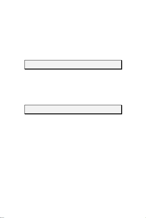
EYE-SPY
TM
AV-620
PASSIVE INFRARED DETECTOR
Installation Instructions
Preliminary Considerations
The Eye-Spy supplied without the swivel
bracket, Eye-Spy PRO pack includes the
AV-70 swivel bracket.
Choose the mounting location after careful
consideration of the protected area.
Downloaded from: http://www.guardianalarms.net
Page 2
The EYE-SPY should be located so that
an intruder will cross the infrared beam
pattern.
Do not mount the unit in direct sunlight,
windy place or near heat sources.
Front Cover Removal
Remove the front cover by twisting a flat
screwdriver in the slot between the cover
and the base at the EYE-SPY bottom.
Mounting Procedure
Without the Swivel
Remove the desired knockouts in the
EYE-SPY base for the mounting screws
and for cable entry.
Insert the cable and attach the bas e to the
wall or corner.
Seal any knockouts that are not in use.
2
Page 3

3 4
Page 4
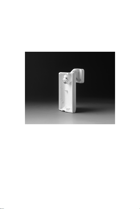
Mounting With the Swivel
The same swivel is used for both wall and
ceiling mounting.
Punch out the rectangular knockout in the
ball joint on the EYE-SPY base. Remove
a knockout at the top of the EYE-SPY
base for cable entry.
Attach the EYE-SPY base to the
with the 3 cm. (1¼ in.) locking screw and
locking disc. Feed the cable into the EYE-
swivel
Page 5
SPY. Two cutouts are provided on the
swivel base for cable entry.
Feed the cable through the hole in the
swivel base and screw the swivel base in
place on the wall or ceiling.
Terminal Connections
Wire the cable to the terminal block at the
bottom of the PC Board as follows:
12V DC: Power supply inputs
ALARM: NC dry contact relay
TAMPER: NC dry contact switch
Seal the hole used for cable entry with
suitable sealant.
PC Board Adjustment
Loosen the PC Board holding screw. Slide
the PC Board so that the plastic pointer
on the right side is positioned at the
5
Page 6
appropriate scale position according to
the lens used, as described below:
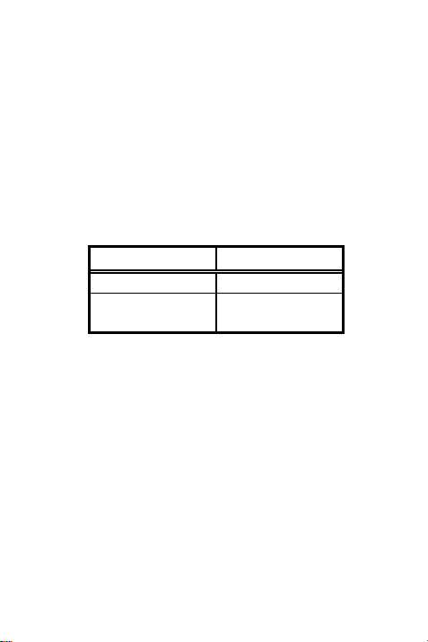
WIDE ANGLE LENS:
Typical mounting height: 2.5 meters (8.2
ft)
.
Scale Position Room Size
SHORT 3-6m (10-20 ft)
LONG 6-15m (20-50
ft)
LONG RANGE LENS:
Typical mounting height: 2.5 meters (8.2
ft).
Select scale position LONG.
PET ALLEY LENS:
Typical mounting height: 1.5 meter (5 ft).
Select scale position PET.
NOTE for other mounting heights and for
finer adjustment of coverage:
6
Page 7

For higher than typical mounting
heights: Slide the PC Board up to reduce
the effective range.
For lower than typical mounting
heights: Slide the PC Board down to
increase the effective range.
Tighten the PC Board holding screw.
Do a walk test as described below and
readjust as necessary until a desired
coverage pattern is reached.
Jumper Settings
LED:
To disable the LED indication, remove the
LED jumper and place it on one pin only.
To enable the LED indication, place the
LED jumper over both pins.
PULSE COUNT:
7
Page 8
Set the PULSE jumper in position 1, 2, or
3, corresponding to the desired pulse
count. Highest sensitivity is at one pulse.
When the Long Range lens is installed,
always set at one (1) pulse count.
Walk Test
Replace the front cover during the walk
test. Apply power and wait at least two
minutes for the detector to stabilize.
8
Page 9
Walk through the entire protected area and
observe the LED to confirm full coverage.
If the swivel is used, adjust it when
necessary.
When adjustment is complete, tighten
the swivel holding screw.
WARNING: This product should be
tested at least once a week.
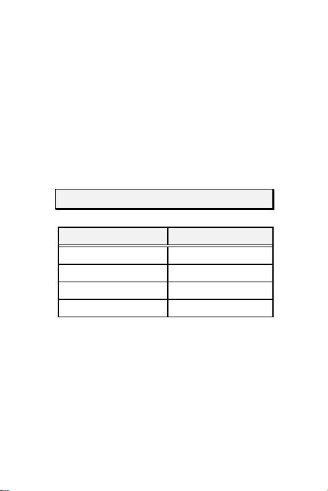
EYE-SPY Lenses
Description: Order Code:
Swivel Bracket AV-70
Wide Angle Lens AV-71 (supplied)
Pet Alley Lens AV-72
Long Range Lens AV-77
PROCEDURE FOR CHANGING
LENSES
Lift off the protective sleeve holding the
lens by pressing on its two holding tabs.
Slide the lens out of the EYE-SPY cover.
Reverse the procedure for inserting a new
lens.
9
Page 10

10 11
Page 11

Av-Gad Limited Warranty
Av-Gad Systems Ltd. and its subsidiaries and
affiliates (“Seller”) warrant its products to be free from
defects in materials and workmanship under normal
use for 12 months from the date of sale. Because Seller
does not install or connect the product and because
the product may be used in conjunction with
products not manufactured by Seller, Seller can not
guarantee the performance of the security system
which uses this product. Seller’s obligation and
liability under this warranty is expressly limited to
repairing or replacing, at Seller’s option, within a
reasonable time after the date of delivery, any product
not meeting the specifications.
SELLER MAKES NO OTHER WARRANTY, EXPRESSED
OR IMPLIED, AND MAKES NO WARRANTY OF
MERCHANTABILITY OR OF FITNESS FOR ANY
PARTICULAR PURPOSE.
IN NO CASE SHALL SELLER BE LIABLE FOR ANY
CONSEQUENTIAL OR INCIDENTAL DAMAGES FOR
BREACH OF THIS OR ANY OTHER WARRANTY,
EXPRESSED OR IMPLIED, OR UPON ANY OTHER
BASIS OF LIABILITY WHATSOEVER.
Seller’s obligation under this warranty shall not
include any transportation charges or costs of
installation or any liability for direct, indirect or
consequential damages or delay.
Seller does not represent that its products may not be
compromised or circumvented; that the product will
prevent any personal injury or property loss by
burglary, robbery, fire or otherwise; or that the
Page 12

product will in all cases provide adequate warning or
protection. Buyer understands that a properly
installed and maintained alarm may only reduce the
risk of burglary, robbery or fire without warning, but
it is not insurance or a guarantee that such will not
occur or that there will be no personal injury or
property loss as a result.
SHALL HAVE NO LIABILITY FOR ANY PERSONAL
INJURY, PROPERTY DAMAGE OR OTHER LOSS BASED
ON A CLAIM THAT THE PRODUCT FAILS TO GIVE
WARNING. HOWEVER, IF SELLER IS HELD LIABLE,
WHETHER DIRECTLY OR INDIRECTLY, FOR ANY
LOSS OR DAMAGE ARISING UNDER THIS LIMITED
WARRANTY OR OTHERWISE, REGARDLESS OF CAUSE
OF ORIGIN, SELLER’S MAXIMUM LIABILITY SHALL
NOT IN ANY CASE EXCEED THE PURCHASE PRICE OF
THE PRODUCT, WHICH SHALL BE THE COMPLETE
AND EXCLUSIVE REMEDY AGAINST SELLER.
CONSEQUENTLY, SELLER
No employee or representative of
Seller is authorized to change this
warranty in any way or grant any other
warranty.
WARNING: This product should be
tested at least once a week.
12
Page 13

Specifications
Operating Voltage: 9 to 16V DC
Current: 17 mA at 12 volts (with LED
off)
Alarm Contacts: 0.1 amps, 24 volts, N.C.
Tamper Contacts: 0.5 amps, 24 volts,
N.C.
Size without swivel: 9.5x6.8x3.9 cm
(3.6x2.5x1.5 in.)
Swivel Adjustment:
Horizontal: ± 25° Vertical: +5 °, -20°
Optical Filtering:
White light protection, pigmented lens
Operating Temperature: -10 to +50oC
(+14 to +122
o
F)
Temperature Compensation:
Automatically
Storage Temperature: -20 to +55oC (-4
o
to +131
F)
Av-Gad Systems Ltd.
84, Ben-Zvi St. Tel-Aviv, Israel
13
Page 14

Tel: (972)-3-681 67 67. Fax: (972)-3-683
5505
Av-Gad systems Ltd., EYE-SPY, 1/2000
Eye-Spy is a registered trademark of AvGad Systems Ltd.
Visit us at http//www.av-gad.com
14
 Loading...