

AV-GAD EasyLoader AV-701TS, EasyLoader AV-701TI, EasyLoader AV-706TP, EasyLoader AV-701TIP, AV-702 Installation Instructions Manual
...
AV-706 & AV-701 Series
INSTALLATION INSTRUCTIONS
Description
The AV-706 and AV-701 Series 4-wire Remote Control Station and Programmer Keypad are
designed for use with Av -Gad EASYLOADER Control Panels. AV-706 fits only the PRO panels.
The AV-706 and AV-701 Series are easy to install and to use keypads. Large 7-Segment and LCD
alphanumeric display provide readout for all control panels information and zone identification.
Installation Instructions Press Down firmly on both tabs and pull
l Before handling keypad, make sure your
hands are clean
l Do not use unnecessary force in opening
and closing the keypad
l Protective Miler sheet may be pilled from the
panel after installation is complete
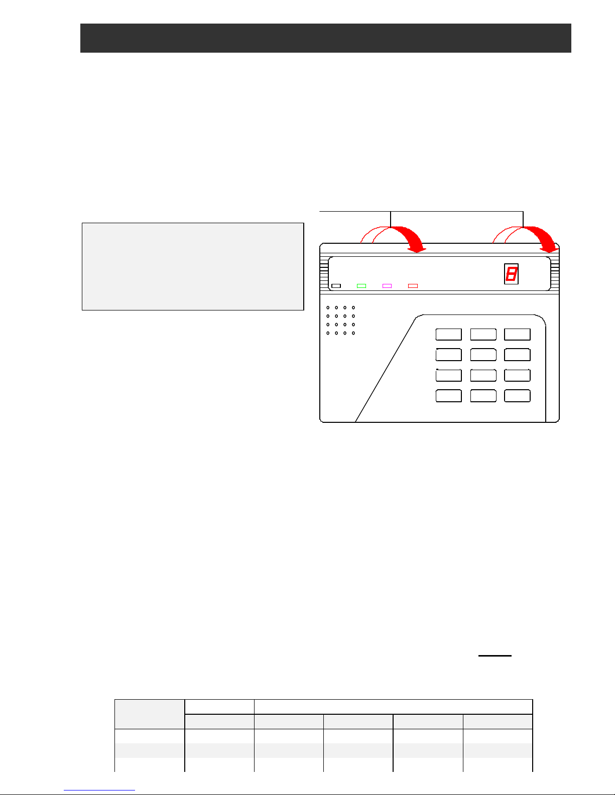
Step One: Opening the keypad
Locate the two rectangular tabs on the top
of the keypad (about 35 mm / 1.5 inches
from each side). Press down on both
tabs firmly and pull front panel of keypad
toward you from the top (see Figure 1.)
Figure 1: Opening the keypad
Step Two: Mounting onto Wall
Place the keypad on wall, at 1.5-1.8 meters height . Make sure the two “UP” arrows word, are
upwards. Attach housing to wall with flat-head screws (use screws that are suitable for the wall
material).
Before affixing to wall, make sure all wires have been inserted through the opening in the
rear of housing. If wires come up from the floor, they may be inserted through the square
slot on the left side of the rear housing. (Using a small screwdriver, try opening the slot with a
twisting action.)
Step Three: Wiring
Insert wires through the opening in the rear of housing. (Note maximum wire lengths in the
following table.) Make sure keypad wires are as far away as possible from telephone and
high power radio transmitter or other electrically “noisy” wires or appliances. For longer run
distance use thicker wire, e.g. 1 mm2.
It is recommended to run keypad wires separately in a 4 or 6 wire cable. Do not run
telephone, sensors or main electric wires in the same cable or electric pipe.
Keypad Function Terminals
Terminal AV-2016/P AV-2004/48 AV-2005 AV-2008
OR Data OR OR OR OR
YE Strobe YE YE YE YE
+12V + Power +12V +12V +12V +12V
*
7
4
1
0
8
5
2
#
9
6
3
Siren
Shunt
Display Status
Delay
Delete
Chime
Test Program Reset
Shunt
Telephone
ARMED STATUS SHUNT FIRE
ZONE
DISPLAY
EASYLOADER AV-701
AV-GAD
Downloaded from: http://www.guardianalarms.net

-12V - Power -V -V -V -V
Max. Cable (6 x 0.5 mm) length
150 meters 100 meters 100 meters 100 meters
Installation Instructions AV-706 & AV-701
Step Four (optional): Connecting more than one keypad
For connection of more than one keypad to the same control panel, first refer to “Control
Panel Manual” for maximum keypad allowance. Connect all keypads in parallel to control
panel by choosing one the ways below:
1. By running wires from each keypad directly to control panel (recommended)
2. By running wires from one keypad to another and then to control panel – avoid this wiring
Step Five: Closing the keypad
Before closing, check keypad(s) to make sure they operate properly, arrange wires to be compact
as possible at the rear housing, left side.
To connect the front keypad to mounted part, fit the two lower slots (note 2 at fig.2) onto the
two protruding tabs on the mounted bottom part, push front part forward and press firmly
until top slots and tabs snap together. Make sure that all sides are securely closed.
Note: There are two additional small tabs on upper and lower inner sides of the housing.
These tabs ensure tighter closure. However, if you encounter difficulty in closing the unit,
you can cut off the tabs (note 1 at fig. 2). This will slightly decrease the tightness of the
closure.
Note 1: Two additional sma ll tabs for tighten closure
Note 2: Fit the two slots onto the two protruding tabs
Back Illumination
The 706 and 701 Series keypad feature timed back
illumination. Two LED’s backlight dimly illuminates the
keypad’s key when keys are not active.
Pressi ng any key will increase brightness of backlight,
which will remain bright for about 10 seconds after last
key is pressed. This feature requires no additional
wiring.
When keys are fully lit, current consumption rises by 50
mA. AV-701TI current consumption with dim lighting is
90 mA, AV-706 consumption is 130mA.
Tamper Switch
Model s AV-701TIP and AV-706TP feature a tamper
switch, which requires one additional wire. Figure 2: Closing the keypad
Connect to TMP and -V on the wire terminal.
Wire the tamper to any zone programmed as either TAMPER or 24H zone. Upon opening the
keypad housing the tamper switch will activate the connected zone.
Ordering Information
AV-701TS: Semi - Illuminated keypad AV-706: LCD illuminated keypad
AV-701TI: Timed illuminated keypad AV-706TP: LCD illuminated keypad + tamper
Wire Terminal
Cut to disable buzzer

AV-701TIP: Timed illuminated keypad + tamper
www.av-gad.com Item 4763/W6/701INS_E2/ All rights reserved to Av-Gad Systems Ltd. 2000
For operating and programming instructions,
please refer to your “Easyloader” operating and
installation manual.
AV-706 keypads are compatible with AV-2005/8
PRO control panels
 Loading...