

465153 rev00
##
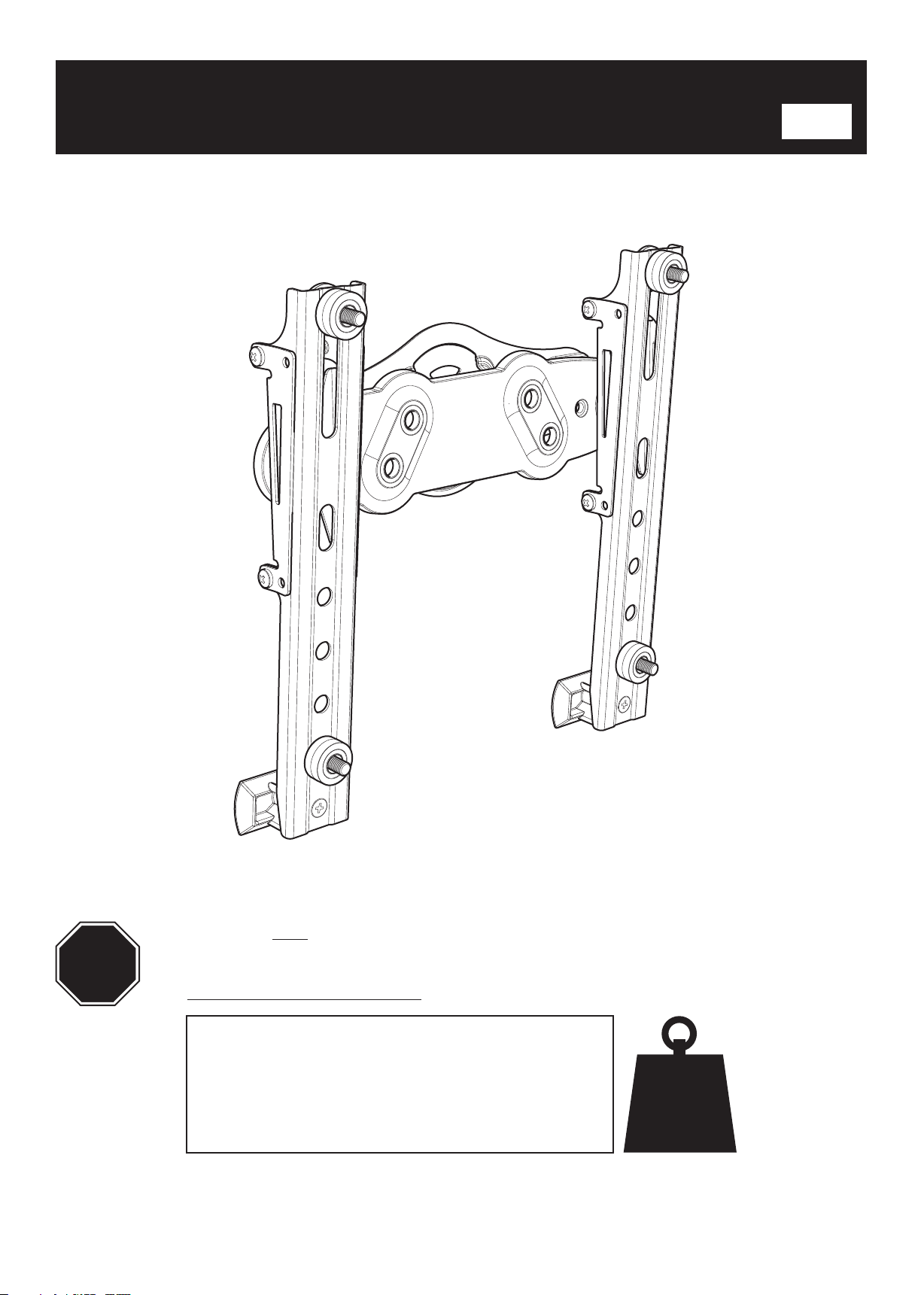
STOP
Read through ALL instructions before commencing installation.
If you have any questions about this product or issues with installation contact
the customer services help line before returning this product to the store.
See www.avfgroup.com/unimax for instruction video.
CUSTOMER SERVICES HELP LINE NUMBER:
+44 (0)1952 670009 (UK)
44lbs
1-800 667 0808 (USA)
20kg
AVF Group Ltd. Hortonwood 30, Telford, Shropshire, TF1 7YE, England
AVF Incorporated 3187, Cornerstone Drive, Eastvale, CA 91752, USA
www.avfgroup.com
1
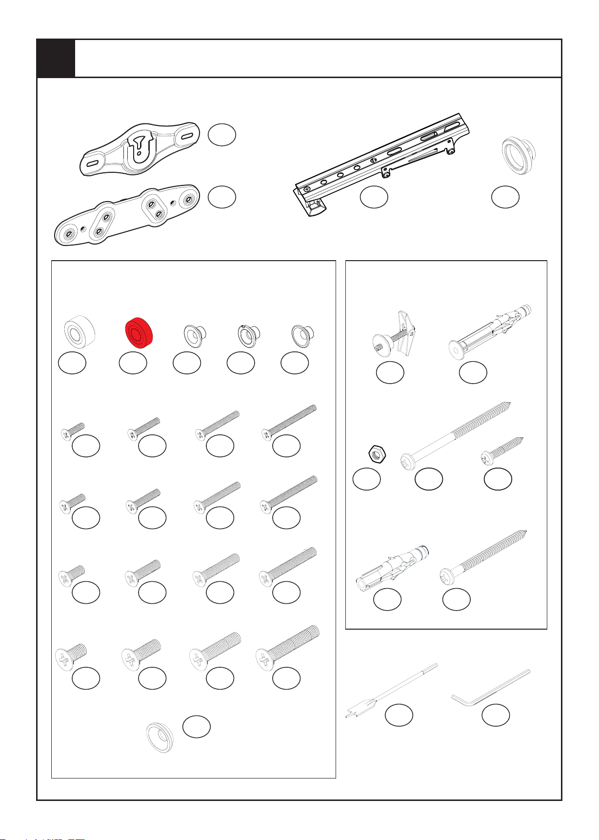
Boxed Parts
You will not need all these parts, so expect there to be some left over depending upon the
specification of your TV.
- x1
A
Wall Bracket
- x1
B
Hanger
TV Fixings: Parts go on the back of the TV
(specification of your TV will determine
which ones you require - see section 9).
- x12
D1
Spacer
F1
M4 16mm
- x4
- x4
D2
Spacer
(Red)
- x4 - x4
F2 F3
M4 25mm M4 35mm
- x4
E1
M4
Adaptor
- x4
E2
M5
Adaptor
F4
M4 45mm
- x4
E3
M6
Adaptor
- x4
- x2
Q
Tilt Bracket
Wall Fixings: Parts to attach to the
wall (type of wall will determine
which fixings you require).
- x2 - x2
G H
Wall Fixing Long Wall Plug
No.14 x 105mm
- x4
I
J K
No.12 x 25mm
- x2 - x1
- x2
C
Stand-off
- x4
F5
M5 16mm
- x4
F9
M6 16mm
- x6
F13
M8 16mm
- x4 - x4
F6 F7
M5 25mm M5 35mm
- x4 - x4
F10 F11
M6 25mm M6 35mm
- x4 - x4
F14 F15
M8 25mm M8 35mm
- x4
P
Housing
- x4
F8
M5 45mm
- x4
F12
M6 45mm
- x4
F16
M8 45mm
Lock Nut
Wall Plug
Included Tools
18mm Wood
Long Screw Metal Stud
- x2
L
- x1
N
Drill
Screw
No.14 x 70mm
- x2
M
Screw
O
3mm Hex
Key
- x1
2
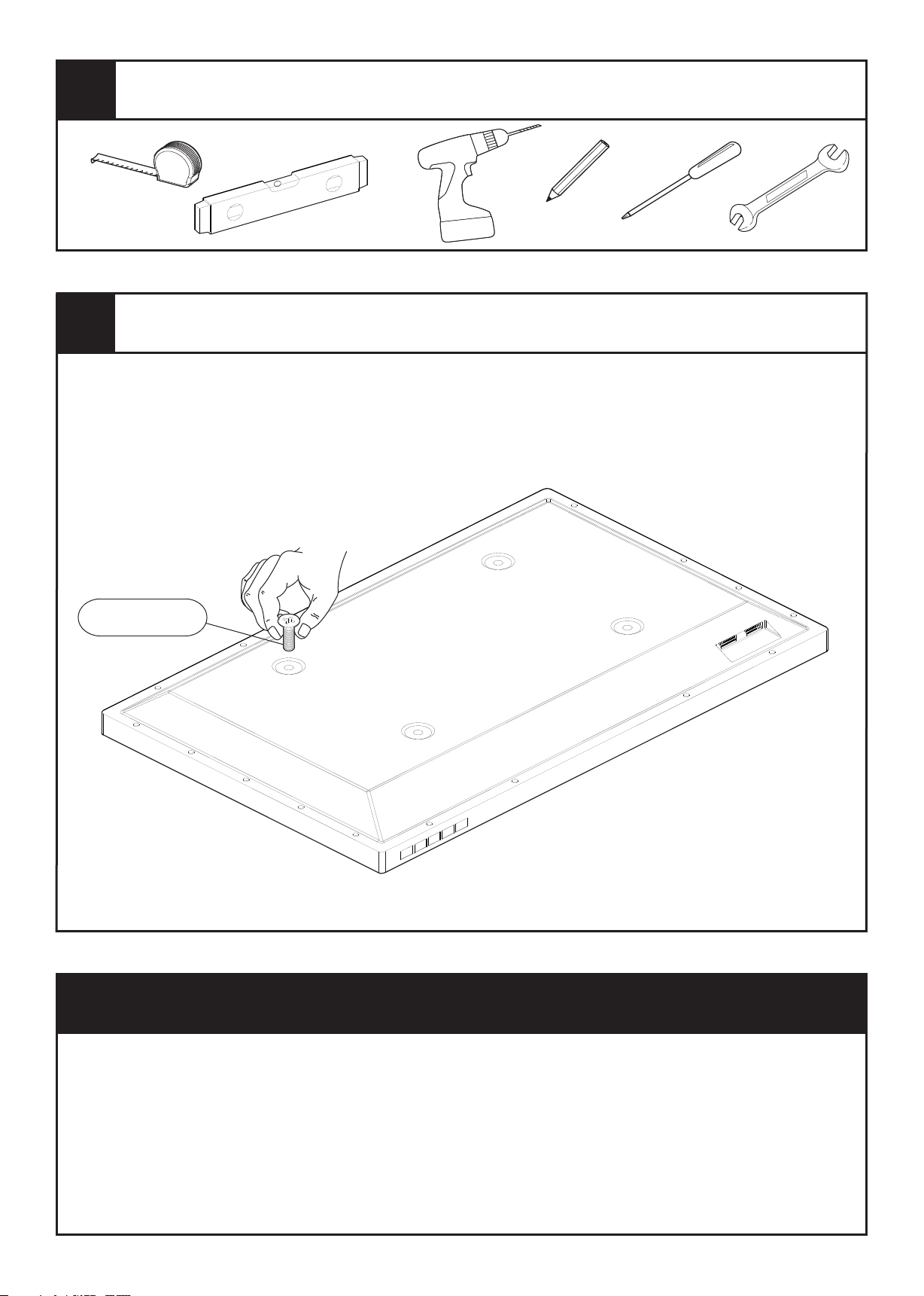
Tools Required
3
Choose from the TV Fixings selection. You need to determine which length and diameter of screws
fits your TV. To determine the correct screw diameter, try screwing (F1), (F5), (F9) & (F13) into one
of the fixing holes on the back of the screen until you find the one that fits. Note the thread size and
ensure you use the appropriate diameter screws.
Determine Correct TV Screw Size
F1, 5 , 9, 13
Flat or Tilt?
Before you start please choose if you would like your TV to be either Flat to Wall or in a Tilt position.
Flat to Wall
Follow steps 4 to 9
Tilt Position
Follow steps 10 to 17
Flat Position
You will only need to follow steps 4 to 9 if you have chosen to have your TV in a flat position
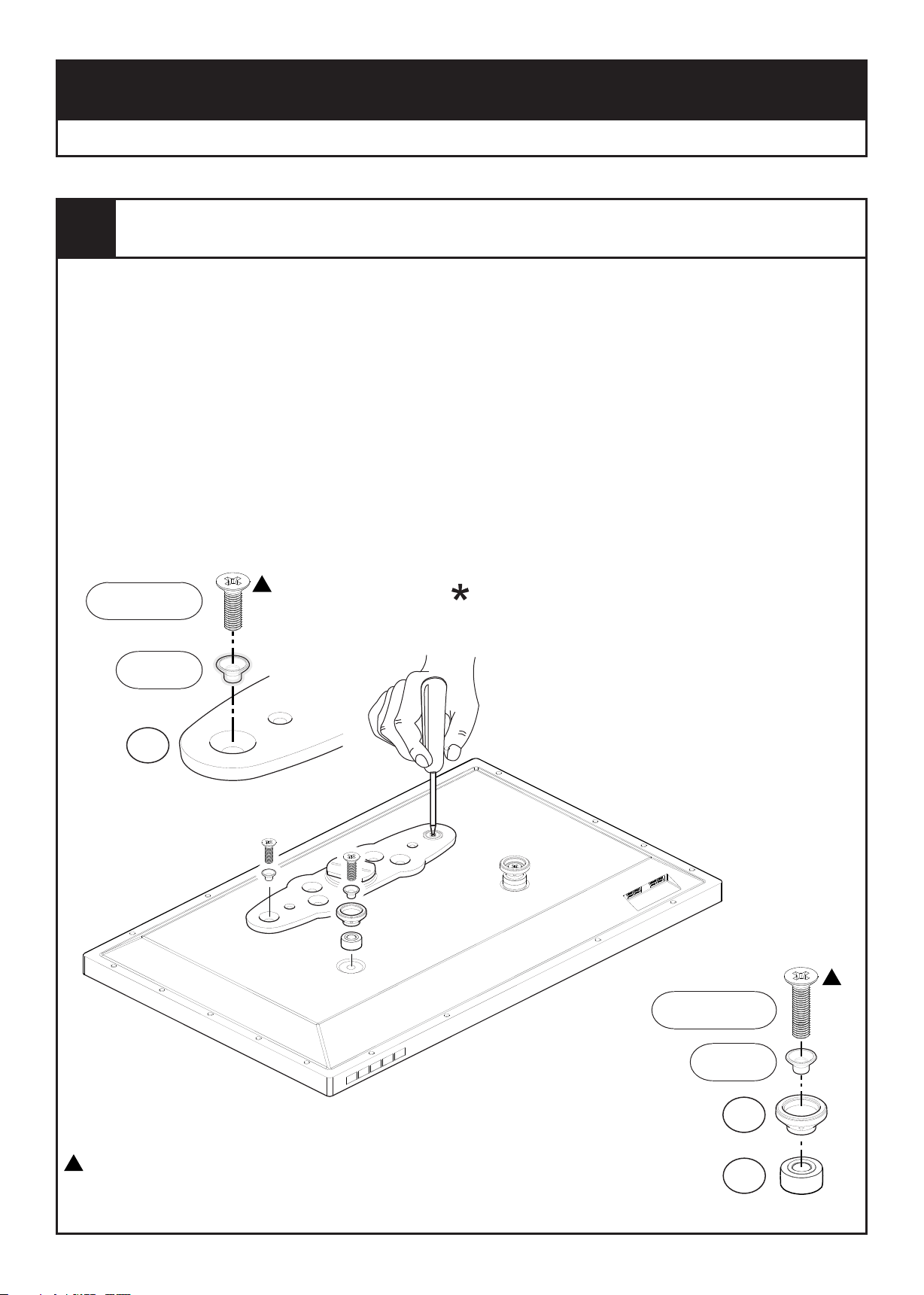
4
Once you have established which screws you need for your TV you can attach the Adaptor (B)
and Stand-offs (C) to the back of your TV.
Typical recommended examples shown are for fixings with the TV spaced 20mm from the wall.
The TV Mount can position your TV between 20mm and 40mm from the wall. For alternative
configurations see sections 9.
You might need to use spacers to increase the clearance of your TV from the wall in order to avoid
cables coming out of your TV and improve access and ventilation to the back of your TV (spacers
(D1) allow you to have a gap of 30mm or 40mm, see section 9).
In certain circumstances it may be necessary to use red spacer ( ) as either a replacement or
addition to spacer ( ), for more information please see section 9.
If your TV fixing centres don’t fit, STOP installation and contact the customer services helpline.
Fit Screen Hangers To TV
D2
D1
Top Fixings
F1, 5 ,9, 13
E1, 2, 3
*
Use adapter with screws (E1) (F1) & (F2)
Use adapter (E2) with screws (F5) & (F6)
Use adapter (E3) with screws (F9) & (F10)
No adapter required with screws (F13) & (F14)
TV must be parallel to wall.
B
Use spacers / stand-offs as shown.
F2, 6 ,10, 14
If you use screw for top fixing you must use screw F1 F2 for bottom fixing
If you use screw F5 for top fixing you must use screw F6 for bottom fixing
If you use screw F9 for top fixing you must use screw F10 for bottom fixing
If you use screw F13 for top fixing you must use screw F14 for bottom fixing
Bottom Fixings
E1, 2, 3
*
C
D1
5
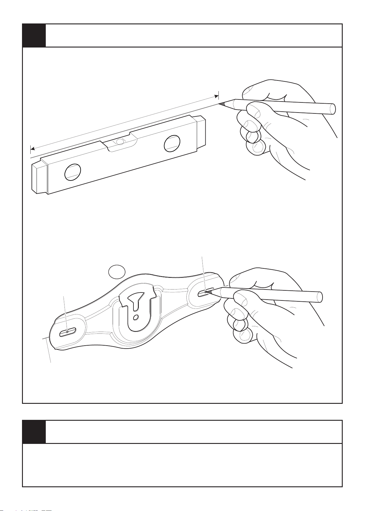
Marking Wall For Drill Points
Decide the position of your wall bracket
and using a pencil lightly draw a straight,
level line approx 220mm long.
approx
220mm
Use the Wall Bracket (A) as a template and
position it on your wall. Ensure the bracket
lines up with the line you have previously
drawn and mark the two DRILL POINTS
with a pencil.
A
Drill point
Pencil Line
Drill point
6
Determine the wall type that you have (i.e. Brick/Stud/Plasterboard/Sheetrock).
Ensure the drilling area is free from mains services (Gas/Electric/Water).
Drill two 3mm diameter pilot holes to verify the wall type and select the appropriate fixings
(See Section 7).
Planning & Preparation

7
Use the correct fixings for your wall type. Mixing fixing types may be required for installations that
span different wall types. DO NOT OVER TIGHTEN SCREWS.
Install Wall Fixings
75mm (3")
Concrete
Remove
dust from
holes
Solid WallDot & DabPlasterboard
108mm
(41/4")
40mm Max
(19/16")
*
Remove
dust from holes
Ø10mm
(25/64")
Ø10mm
(25/64")
If gap is above 40mm use
Plasterboard / Sheetrock fixing method
*
L
H
(19/16")
NMLKJIHGA
A
Lubricate screw
thread with soap
A
Lubricate screw
thread with soap
O
M
J
Ø18mm
(3/4")
G O
Turn until secure
Do not over
tighten
A
N
I
/ Sheetrock
40mm (19/16") Min gap
Ø3mm
(1/8")
Use Plasterboard /
Sheetrock fixings
Lubricate screw
thread with soap
A
Use Plasterboard
/Sheetrock fixings
M
Wood StudMetal Stud
Only one fixing will be in the wood stud. The other fixings will be in plasterboard / sheetrock (see above).
Use Plasterboard /
Sheetrock fixings
A
Ø3.5mm
(9/64")
Hand tighten
only
Use Plasterboard
/Sheetrock fixings
K
Only one fixing will be in the metal stud. The other fixings will be in plasterboard / sheetrock (see above).

8
Rotate your TV so that the guide marks on the hanger are vertical. Next slide your TV down so
that the hanger goes between the two guide tabs on the wall bracket. Ensure the hanger is fully
engaged and rotate clockwise until your TV is level.
Hanging The TV
Vertical Line
Guide Marks
Hanger
Guide Tabs
If cables from your TV prevent the TV resting against the wall then an alternative hanger
configuration will be required (See Section 9).
TV must be parallel to wall. Use spacers / stand-offs as shown.
I II
III
If required you can adjust
the level of your TV by
slightly rotating your TV.
Removing the TV
This is a two person job. To remove the TV rotate anti-clockwise between 15-30 and lift TV up
and out (ie reverse the movements as shown above).

9
Alternative Hanger Configurations
Alternative Wall spacings of 20mm, 30mm & 40mm can
be achieved using the spacer / screw combinations
listed in this section.
20mm Wall Space
(as shown in section 4)
Wall Space
30mm Wall Space 40mm Wall Space
Top FixingsTop Fixings Top Fixings
F1, 5 ,9, 13
E1, 2, 3
*
B
F2, 6,10, 14
E1, 2, 3
*
C
D1
F2, 6,10, 14
E1, 2, 3
*
B
D1
F3, 7, 11, 15
E1, 2, 3
*
B
D1
D1
Bottom FixingsBottom Fixings Bottom Fixings
F3, 7,11, 15
E1, 2, 3
*
C
D1
F4, 8,12, 16
E1, 2, 3
*
C
D1
D1
D1
D1
TV must be parallel to wall. Use spacers / stand-offs as shown.
Use adapter with screws (E1) (F1), (F2), (F3) & (F4)
Use adapter (E2) with screws (F5), (F6), (F7) & (F8)
Use adapter (E3) with screws (F9), (F10), (F11) & (F12)
*
No adapter required with screws (F13), (F14), (F15) & (F16)
When is it necessary to use red spacers?
D1 D2
Problem
Not enough
screw engagement
It is recommended that when fitting Adaptor ( ) and
Stand-offs ( ) to your TV you have at least 5-10mm of
screw engagement. In certain circumstances you may
need to use red spacers ( ) as either a replacement, or
together with spacers ( ) to achieve this. Whenever
TV TV
you use red spacers (D2) you must use all 4 provided.
C
D2
D1
B
- x4
D2
Solution
Red spacer (D2) has
replaced spacer (D1)

Tilt Position
You will only need to follow steps 10 to 17 if you have chosen to have your TV in a tilted position
10
Your bracket can be tilted in 2 different positions, either 5 or 10°. If you choose 5 tilt you will not
need to do anything. If you choose 10 tilt you will need to remove screws as indicated, pull the tilt
bracket forward and replace screws as indicated.
Choose Tilt
I
° °
°
5° 10°
II
III

11
Once you have established which screws you need for your TV you can attach Tilt brackets (Q) to
the back of your TV.
Example shown below is only for TV’s with a flat back. Should you require more space for cables
and to improve access and ventilation to the back of your TV you will need to add spacers ( ),
see section 17.
Fit Tilt Brackets to TV
D1
In certain circumstances it may be necessary to use red spacer ( ) in addition to the fixings
below, for more information see section 17.
If your TV fixing centres don’t fit, STOP installation and contact the customer services helpline.
Top Fixings
D2
F1, 5 ,9, 13
E1, 2, 3
*
P
Q
Bottom Fixings
*
Use adapter with screws (E1) (F1)
Use adapter (E2) with screws (F5)
Use adapter (E3) with screws (F9)
No adapter required with screws (F13)
If you use screw for top fixing you must use screw F1 F1 for bottom fixing
If you use screw F5 for top fixing you must use screw F5 for bottom fixing
If you use screw F9 for top fixing you must use screw F9 for bottom fixing
If you use screw F13 for top fixing you must use screw F13 for bottom fixing
F1, 5 ,9, 13
E1, 2, 3
P
Q

12
Fit Hanger to Tilt Brackets
Attach Hanger (B) to Tilt Brackets (Q).
F13
13
Marking Wall For Drill Points
F13
B
Q
Q
Decide the position of your wall bracket
and using a pencil lightly draw a straight,
level line approx 220mm long.
Use the Wall Bracket (A) as a template
and position it on your wall. Ensure the
bracket lines up with the line you have
previously drawn and mark the two
DRILL POINTS with a pencil.
Pencil Line
approx
220mm
Drill point
Drill point
A
14
Determine the wall type that you have (i.e. Brick/Stud/Plasterboard/Sheetrock).
Ensure the drilling area is free from mains services (Gas/Electric/Water).
Drill two 3mm diameter pilot holes to verify the wall type and select the appropriate fixings
(See Section 15).
Planning & Preparation

15
Use the correct fixings for your wall type. Mixing fixing types may be required for installations that
span different wall types. DO NOT OVER TIGHTEN SCREWS.
Install Wall Fixings
75mm (3")
Concrete
Remove
dust from
holes
Solid WallDot & DabPlasterboard
108mm
(41/4")
40mm Max
(19/16")
*
Remove
dust from holes
Ø10mm
(25/64")
Ø10mm
(25/64")
If gap is above 40mm use
Plasterboard / Sheetrock fixing method
*
L
H
(19/16")
NMLKJIHGA
A
Lubricate screw
thread with soap
A
Lubricate screw
thread with soap
O
M
J
Ø18mm
(3/4")
G O
Turn until secure
Do not over
tighten
A
N
I
/ Sheetrock
40mm (19/16") Min gap
Ø3mm
(1/8")
Use Plasterboard /
Sheetrock fixings
Lubricate screw
thread with soap
A
Use Plasterboard
/Sheetrock fixings
M
Wood StudMetal Stud
Only one fixing will be in the wood stud. The other fixings will be in plasterboard / sheetrock (see above).
Use Plasterboard /
Sheetrock fixings
A
Ø3.5mm
(9/64")
Hand tighten
only
Use Plasterboard
/Sheetrock fixings
K
Only one fixing will be in the metal stud. The other fixings will be in plasterboard / sheetrock (see above).

16
Hanging The TV
Hanger
Guide Tabs
Rotate your TV so that the guide marks on the hanger are vertical. Next slide your TV down so
that the hanger goes between the two guide tabs on the wall bracket. Ensure the hanger is fully
engaged and rotate clockwise until your TV is level.
If cables from your TV prevent the TV resting against the wall then an alternative hanger
configuration will be required (See Section 17).
Vertical Line
Guide Marks
I II
III
If required you can adjust
the level of your TV by
slightly rotating your TV.
Removing the TV
This is a two person job. To remove the TV rotate anti-clockwise between 15-30 and lift TV up
and out (ie reverse the movements as shown above).

17
Alternative spacings can be achieved using the spacer / screw combinations shown in this section.
Alternative Hanger Configurations
1 Spacer Combination
F2, 6, 10, 14
E1, 2, 3
P
Q
D1
Bottom Fixings
F2, 6, 10, 14
E1, 2, 3
P
2 Spacer Combination 3 Spacer Combination
Top FixingsTop Fixings
F3, 7, 11, 15
E1, 2, 3
P
Q
D1
Bottom Fixings
F3, 7, 11, 15
E1, 2, 3
P
Top Fixings
F4, 8, 12, 16
E1, 2, 3
P
Q
D1
Bottom Fixings
F4, 8, 12, 16
E1, 2, 3
P
Q
D1
Solution
D1
Q
O
- x4
D2
Red spacer (D2) has
replaced spacer (D1)
Q
D1
If using screws use Adapter (E1)(F2), (F3) & (F4)
If using screws (F6), (F7) & (F8) use Adapter (E2)
If using screws (F10), (F11) & (F12) use Adapter (E3)
*
If using screws (F14), (F15) & (F16) no Adapter required
When is it necessary to use red spacers?
D1 D2
Problem
Not enough
screw engagement
It is recommended that when fitting Tilt Brackets ( )
to your TV you have at least 5-10mm of screw
engagement. In certain circumstances you may need
to use red spacers ( ) as either a replacement, or
together with spacers ( ) to achieve this. Whenever
TV TV
you use red spacers (D2) you must use all 4 provided.
D2
D1


 Loading...