


TTX 350

12/03 Rev. 3.00-01 SERVICE MANUAL
TTX 350
General Service
Housing..........................................................2
Important remarks...................................... 2
Overview of the parts of the housing.......... 2
Front cover................................................. 2
Back cover ................................................. 3
Front-left housing .......................................4
Front-right housing..................................... 6
Lower-right housing.................................... 6
Cutter covering...........................................6
Material unwinder...........................................7
General ...................................................... 7
Unwinder.................................................... 7
Strain relief................................................. 8
Connections and electrics..............................9
Important remarks...................................... 9
Mains connection .......................................9
Transformer.............................................. 11
Ventilator.................................................. 12
Sensors........................................................13
Overview of sensors................................. 13
Printed circuit boards....................................14
Printed circuit boards: General .................14
Display board............................................14
Peripheral board .......................................15
CPU board................................................16
Changing the serial interface to RS485
mode.........................................................17
Installing a real-time clock.........................18
Service data..................................................19
Factory setting ..........................................19
Zeroing the operating data........................19
Entering the service data..........................20
Upgrading.....................................................21
Printer versions.........................................21
Upgrading from 8,0 to 11,8 dot.................22
Periphery set-up........................................22
Index.............................................................23
12/03 Rev. 3.00-01 SERVICE MANUAL General Service
TTX 350
2
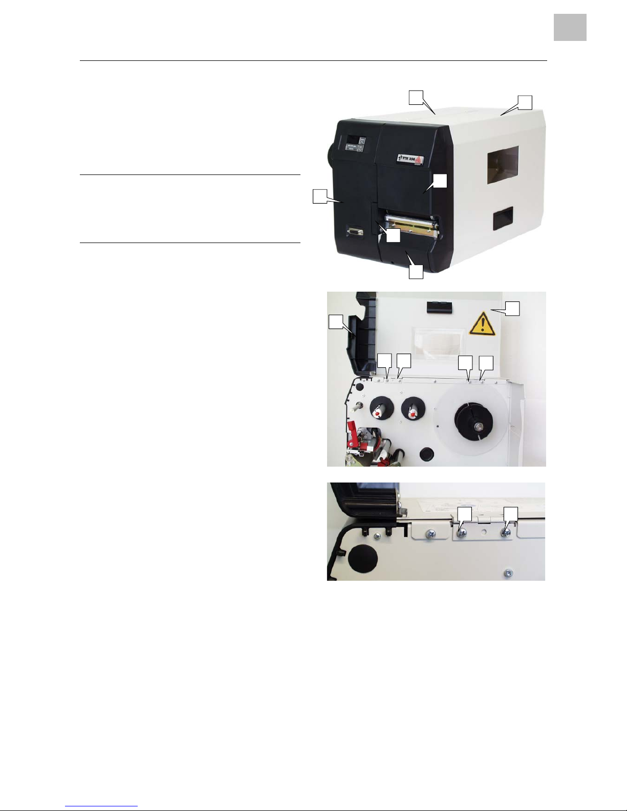
Housing
Important remarks
¯ The housing must only to be opened by
authorised skilled personnel!
¯
Before opening the housing, switch off
the device and disconnect the mains
plug. If this is not done, there is a
danger of an accident due to dangerous
contact voltages.
Overview of the parts of the
housing
The housing consists of the following
individual parts:
– Front cover (1)
– Back cover (2)
– Front-left housing (3)
– Front-right housing (4)
– Lower-right housing (5)
– Cutter covering (6)
– Plug covering (7)
Front cover
Demounting / mounting
£ After opening, the front cover (1) can be
detached by loosening four screws (8)
(Phillips screws).
The front-right housing (4) remains
attached to the front cover.
Tools
– Phillips screwdriver
8
8
8
8
4
2
4
1
1
3
5
6
8 8
12/03 Rev. 3.00-01 SERVICE MANUAL General Service
TTX 350
3
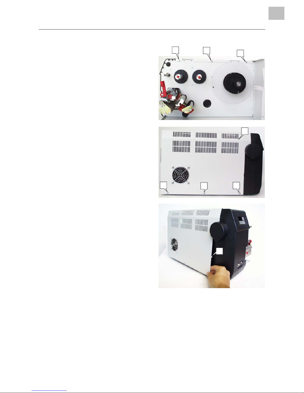
Back cover
Demounting / mounting
£ The back cover (2) can be detached by
loosening 6 Phillips screws (1). Laterally
spread the back cover slightly in order to
lift the metal extension (3) from its
opening. Then lift it carefully in an
upward direction starting from behind.
¯
Disconnect the ventilator cable before
fully removing the back cover!
Tools
– Phillips screwdriver
1
1
1
2
1
1
1
3
12/03 Rev. 3.00-01 SERVICE MANUAL General Service
TTX 350
4
Front-left housing
Demounting / mounting
1. Detach the back cover.
2. Unscrew the earth cable (1) of the cutter
connection from the floor of the housing
(hexagon socket).
3. Disconnect the three plug connections
of the earth connection from the
peripheral board. Loosen the fixtures of
the connection cable. For this, clip
through the cable binders (diagonal
cutter).
4. Disconnect the ribbon contact of the
display on the mainboard. Remove the
cable attachments (cable binders).
5. Loosen the three Phillips screws (2).
P Continued on the next page
2
2
2
1

12/03 Rev. 3.00-01 SERVICE MANUAL General Service
TTX 350
5
6. Carefully detach the front housing (1) to
the side.
P Removal of the display (4) and
peripheral cable harness (5) see section
"Connections and electrical".
Tools
-- Phillips screwdriver
-- hexagon socket 3 mm
3
4
5
12/03 Rev. 3.00-01 SERVICE MANUAL General Service
TTX 350
6
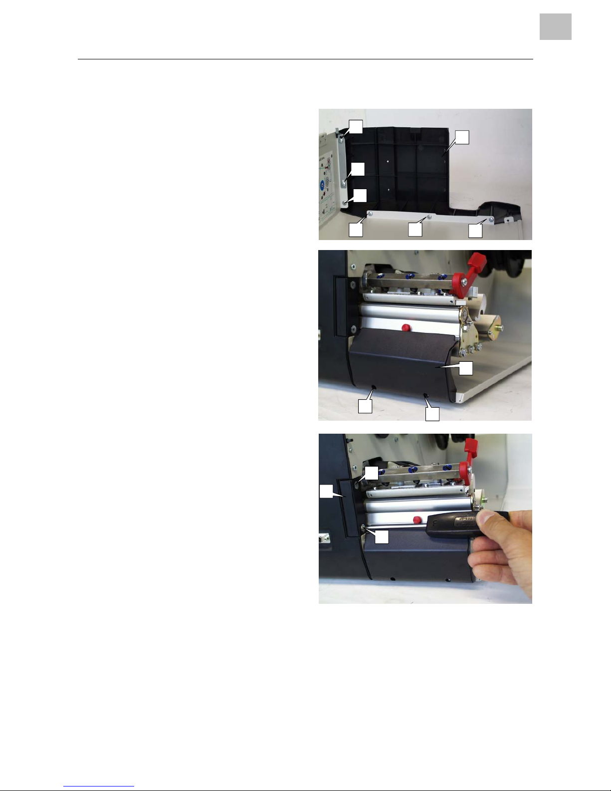
Front-right housing
Demounting / mounting
£ The front-right housing (1) is attached to
the front cover with six Phillips screws
(2) and is detachable.
Tools
Phillips screwdriver
Lower-right housing
Demounting / mounting
£ The lower-right housing (3) is attached
to the base tray with two hexagonal
screws (4) and is detachable.
Tools
Hexagon socket size 2.5
Cutter covering
Demounting / mounting
The cutter covering (5) is attached to the
printing module with two hexagonal
screws (6) and is detachable.
Tools
Hexagon socket size 3
6
2
2
2
2
2
2
1
5
4
4
3
6
12/03 Rev. 3.00-01 SERVICE MANUAL General Service
TTX 350
7
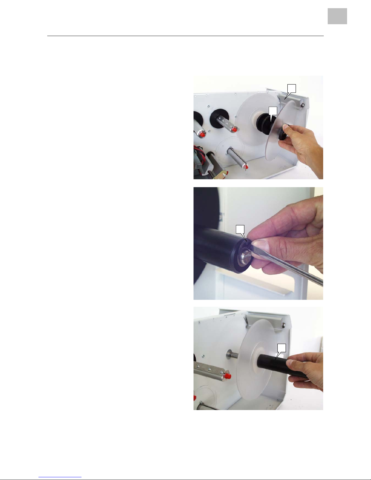
Material unwinder
General
The material unwinder consists of the
unwinder (1) and the strain relief (2). The
strain relief has the purpose of compensating
the jolting material movements which can
occur if large speed increases or decreases
(braking) in the material feeding rate occur.
The unwinder itself is braked and adjustable
to various core diagonals.
Unwinder
Demounting / mounting
1. Remove material guide disc and take off
adapter rings
1. Remove guard ring (3).
2. Remove the entire unwinder core (4).
£ When mounting:
Pay attention to easy accessibility and
check the brake (where necessary,
lubricate the unwinder axis).
Tools
– Screwdriver
2
1
3
4
 Loading...