

Page 1

AVerMedia®
AVerDiGi
Wireless/Wired IP Camera
SF1301W
SF1301
User Manual
May 2009
Page 2

Page 3

CONTENTS
CHAPTER 1 INTRODUCTION ........................................................................................................................ 1
1.1 Features and Benefits .............................................................................................................................. 1
1.2 Package Contents .................................................................................................................................... 2
1.1.1 SF1301W (Wireless) ............................................................................................................................ 2
1.1.2 SF1301 (Wired) .................................................................................................................................... 2
1.3 System Requirements .............................................................................................................................. 3
1.4 Default Settings ........................................................................................................................................ 3
1.5 LED Indicators .......................................................................................................................................... 4
1.6 Rear Panel ................................................................................................................................................. 4
1.6.1 SF1301W ............................................................................................................................................. 4
1.6.2 SF1301 ................................................................................................................................................ 5
1.6.3 Using the WPS Button (Only SF1301W) ............................................................................................. 6
CHAPTER 2 INSTALLING THE CAMERA ..................................................................................................... 7
2.1 Attach Camera to the Stand .................................................................................................................... 7
2.2 Connect Ethernet Cable ........................................................................................................................... 7
2.3 Connect Power and Power On Camera .................................................................................................. 8
2.4 Reset Camera ........................................................................................................................................... 8
CHAPTER 3 USING THE CAMERA WEB MANAGER .................................................................................. 9
3.1 First Time to Use the IP Camera ............................................................................................................. 9
3.2 Familiarizing the Function Buttons in Live Video Viewer ................................................................... 16
3.3 IP Camera Setup ..................................................................................................................................... 18
3.3.1 Setup Wizard ..................................................................................................................................... 18
3.3.2 Network Settings ................................................................................................................................ 22
3.3.3 Wireless Setup ................................................................................................................................... 25
3.3.4 Image Setup....................................................................................................................................... 26
3.3.5 Video and Audio Settings ................................................................................................................... 27
3.3.6 Motion Detection ................................................................................................................................ 30
3.3.7 Time and Date ................................................................................................................................... 31
3.3.8 Recording Setup ................................................................................................................................ 32
3.3.9 Snapshot Setup ................................................................................................................................. 34
3.4 System Configuration ............................................................................................................................ 36
3.4.1 Device Management .......................................................................................................................... 37
3.4.2 Backup and Restore Setup ................................................................................................................ 38
3.4.3 Firmware Upgrade ............................................................................................................................. 39
3.4.4 Device Information ............................................................................................................................. 40
3.4.5 Camera Log ....................................................................................................................................... 40
CHAPTER 4 IPCAMCENTER ....................................................................................................................... 41
4.1 Install the IPCamCenter ......................................................................................................................... 41
4.2 Using the IPCamCenter ......................................................................................................................... 43
Page 4

4.2.1 To Connect the Camera ..................................................................................................................... 43
4.2.2 Familiarizing the Buttons in the IPCamCenter ................................................................................... 45
4.3 System Configuration ............................................................................................................................ 47
4.3.1 Camera Management ........................................................................................................................ 48
4.3.2 Camera Setting .................................................................................................................................. 49
4.3.3 Recording Option ............................................................................................................................... 56
4.3.4 Other Options..................................................................................................................................... 56
4.4 Playback the Recorded File ................................................................................................................... 58
APPENDIX A TECHNICAL SPECIFICATIONS ........................................................................................... 59
Page 5

FCC NOTICE (Class B)
This device complies with Part 15 of the FCC Rules. Operation is subject to the following two conditions: (1) this device may
not cause harmful interference, and (2) this device must accept any interference re ceived, including interference that may
cause undesired operation.
Federal Communications Commission Statement
NOTE - This equipment has been tested and found to comply with the limits for a Class B digital device, pursuant to Part 15 of the FCC
Rules. These limits are designed to provide reasonable protection against harmful interference in a residential installation. This
equipment generates uses and can radiate radio frequ ency energy and, if not installed and used in accordance with the instructions,
may cause harmful interference to radio communications. However, there is no guarantee that interference will not occur in a particular
installation. If this equipment does cause harmful interference to radio or television reception, which can be determined by tuning the
equipment off and on, the user is encouraged to try to correct the interference by one or more of the following measures:
Reorient or relocate the receiving antenna.
Increase the separation between the equipment and receiver.
Connect the equipment into an outlet on a circuit different from that to
which the receiver is connected.
Consult the dealer or an experienced radio/television technician for help.
European Community Compliance Statement (Class B)
This product is herewith confirmed to comply with the requirements set out in the Council Directives on the Approximation of
the laws of the Member States relating to Electromagnetic Compatibility Directive 2004/108/EC.
DISCLAIMER
No warranty or representation, either expressed or implied, is made with respect to the contents of this documentation, its quality,
performance, merchantability, or fitness for a particular purpose. Information presented in this documentation has been carefully
checked for reliability; however, no responsibility is assumed for inaccuracies. The information contained in this documentation is
subject to change without notice.
In no event will AVerMedia be liable for direct, indirect, special, incidental, or consequential damages arising out of the use or inability to
use this product or documentation, even if advised of the possibility of such damages.
TRADEMARKS
"AVerMedia" is a trademark (or registered trademark) of AVerMedia Technologies, Inc and has been authorized AVerMedia Information
Inc to use.
Other trademarks used herein for description purpose only belong to each of their companies.
COPYRIGHT
©2009 by AVerMedia Information, Inc. All right reserved.
No part of this document may be reproduced or transmitted in any form, or by any means without the prior written permission of
AVerMedia Information Inc. AVerMedia Information Inc. reserves the right to modify its models, including their characteristics,
specifications, accessories and any other information stated herein without notice. The official printout of any information shall prevail
should there be any discrepancy between the information contained herein and the information contained in that printout.
Page 6
WARNING
TO REDUCE RISK OF FIRE OR ELECTRIC SHOCK, DO NOT EXPOSE THIS
APPLIANCE TO RAIN OR MOISTURE
CAUTION
IF THERE IS ANY DAMAGE, SHORTAGE OR INAPPROPRIATE ITEM IN THE
PACKAGE, PLEASE CONTACT WITH YOUR LOCAL DEALER. WARRANTY VOID FOR
ANY UNAUTHORIZED PRODUCT MODIFICATION
NOTICE
- INFORMATION IN THIS DOCUMENT IS SUBJECT TO CHANGE WITHOUT NOTICE.
- THE INFORMATION CONTAINED HEREIN IS TO BE CONSIDERED FOR
REFERENCE ONLY.
Page 7

About This User Manual
This user manual provides instructions on how to install the IP camera and use it for camera monitoring
applications. Camera monitor applications are accessible through an Ethernet or 802.11g wireless local
network.
Before You Start
Please read and make sure you understand all the prerequisites for proper installation of your new IP camera.
Have all the necessary information and equipment on hand before beginning the installation.
Page 8

Page 9

Chapter 1 Introduction
The SF1301 and SF1301W IP Camera transmit live real-time high-quality MPEG-4 video through an Ethernet
network or 802.11g wireless LAN useful for remote monitoring applications. The live video can be viewed
remotely and managed through the network from any computer connected to the network. A built-in
microphone allows synchronized audio and high-quality video monitoring.
1.1 Features and Benefits
Easy to use - The camera supports DirectX 9.0; therefore, the only requirement you need is the web browser
software such as Internet Explorer 6.0 or above. Once you have a valid IP Address, just connect it and you
can view the picture and receive sound from your camera. In addition, the camera’s stand allows you to adjust
the camera for optimal viewing angle.
Support variety of platforms - The camera supports TCP/IP networking, SMTP e-mail, HTTP and other
Internet related protocols. It can be utilized in a mixed operating system environment, including Windows 9
2000/XP/Vista. Moreover, it can be integrated easily into other www/ Intranet applications.
Web configuration - Applying a standard web browser, the administrator can configure and manage the
camera directly from its own web page via the Intranet or Internet. Up to 20 user accounts are permitted with
privilege setting controlled by the administrator.
Remote Utility - The powerful IPCamWizard application assigns the administrator with a pre-defined user ID
and password, allowing the administrator to modify the camera settings from the remote site via Intranet or
Internet. When new firmware is available, you can also upgrade remotely over the network for added
convenience. Users are also allowed to monitor the image, and take snapshots.
Broad Range of Applications - With today’s high-speed Internet services, the camera can provide the ideal
solution for live video images over the Intranet or Internet for remote monitoring. The camera allows remote
access from a web browser for live image viewing, and allows the administrator to manage and control the
camera anywhere and anytime in the world. Apply the camera to monitor various objects and places such as
homes, offices, banks, hospitals, child-care centers, amusement parks and other varieties of industrial and
public monitoring. The camera can also be used for intruder detection; in addition, it can capture still images
for archiving and many more applications.
1
Page 10
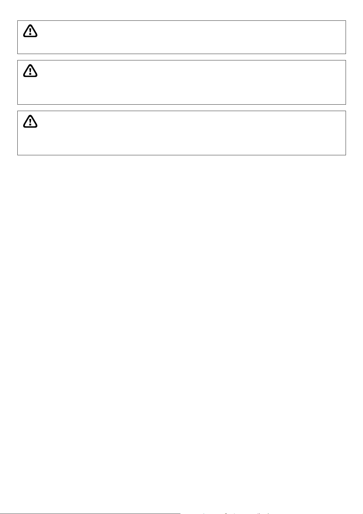
1.2 Package Contents
1.1.1 SF1301W (Wireless)
SF1301W Power Adapt er RJ-45 Ethernet Cable
Antenna Camera Stand Installation CD-ROM
1.1.2 SF1301 (Wired)
SF1301 Power Adapter RJ-45 Ethernet Cable
Camera Stand Installation CD-ROM
i
If there is any damage, shortage or inappropriate item in the package contents, please contact with local dealer
WARNING
WARRANTY VOID FOR ANY UNAUTHORIZED PRODUCT MODIFICATION
2
Page 11

1.3 System Requirements
Computer
CPU
OS
Memory
VGA Resolution
Ethernet
Media
Intel Celeron 1.1 GHz or above
Microsoft® Windows 2000/XP/Vista
128 MB or above
800 x 600 or above
10BASE-T Ethernet or 100BASE-TX Fast Ethernet
CD-ROM Drive
Network
9 Local Area Network: 10Base-T Ethernet or 100Base-TX Fast Ethernet
9 Wireless Local Area Network (wireless model): IEEE 802.11g Wireless LAN
1.4 Default Settings
Use the default settings to access the web-based management software and live video display.
Default configuration settings
Username
The Username will be prompted to enter when access the IP camera configuration screens
using a Web browser. The default Username is admin.
Password
IP address
Subnet Mask
The Password will be prompted to enter when access the IP camera configuration screens
using a Web browser. The default Password is blank.
The camera default IP address using the DHCP. Using the IPCamWizard to search the
camera for the first time using.
The subnet mask will depend on the IP address of camera has been assigned by DHCP on
your network.
3
Page 12
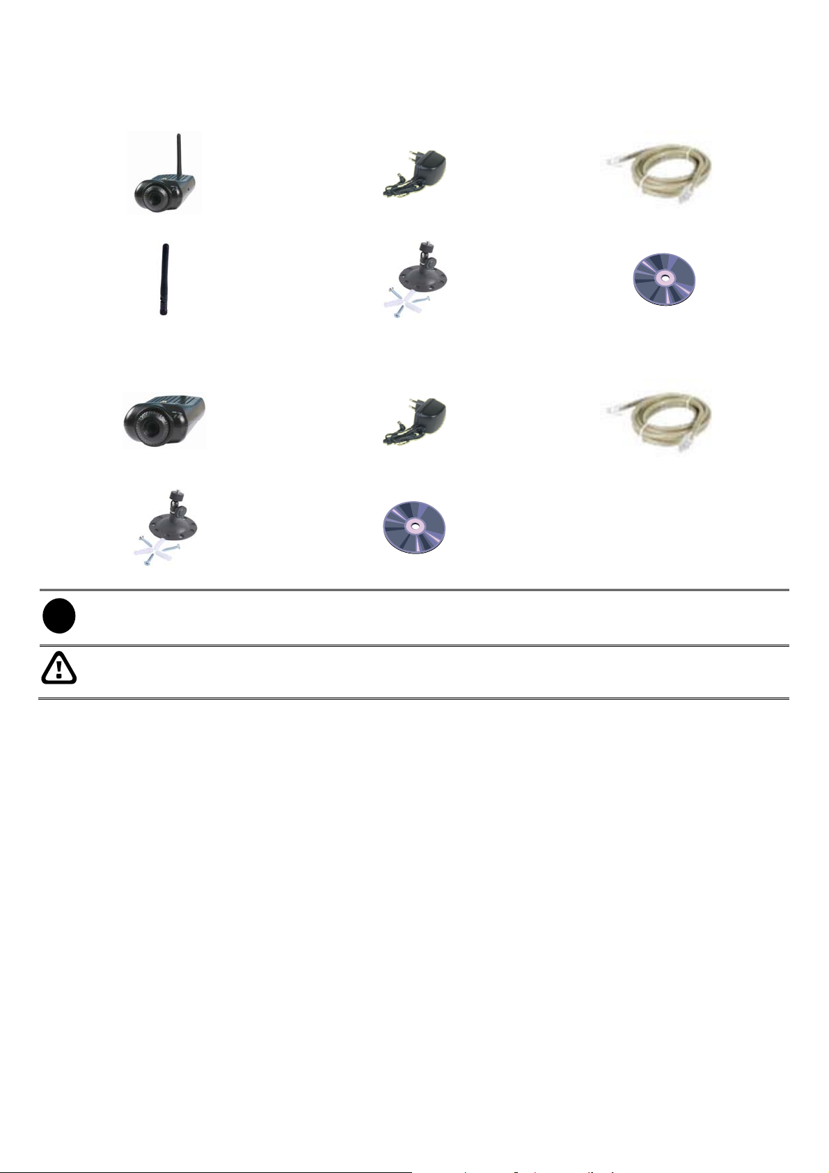
1.5 LED Indicators
Link indicator
Power indicator
The PWR and LNK LED indicators provide the several statuses as the below table listing:
PWR POWER
WPS
LNK Link
Lighting in Blue: IP camera is power on.
Light Off: IP camera is power off.
Success: Lighting and then reboot automatically.
Fail: Blinking about 10 sec, and then reboot automatically.
Lighting in Orange: Ethernet link is valid.
Blinking: Data is transmitted or received through the Ethernet link.
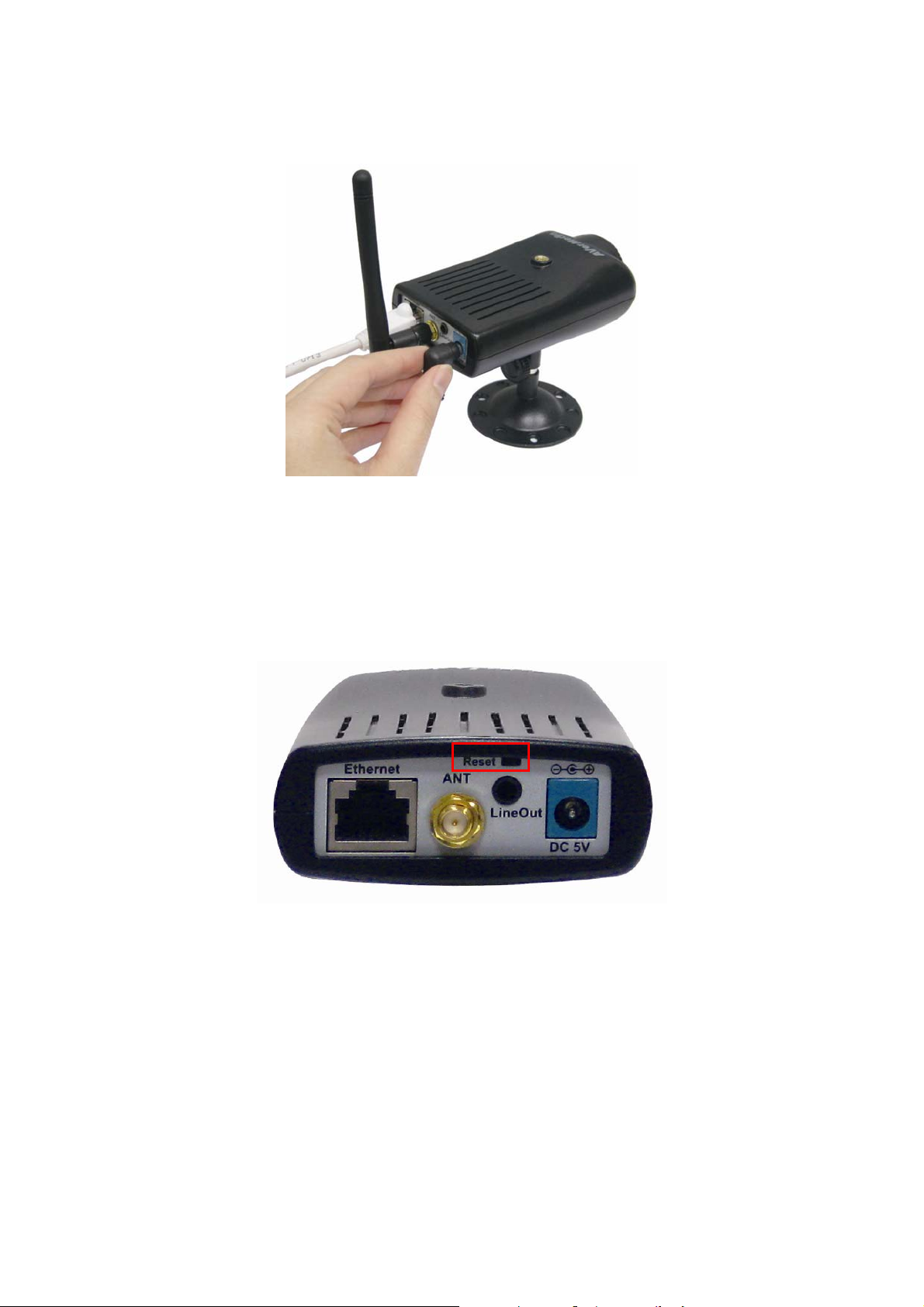
1.6 Rear Panel
1.6.1 SF1301W
Connect the power adapter cord and network cables on the rear panel. The reset button is also located on the
back of the device.
Name Function
(1) Ethernet port For connecting to Ethernet LAN. The port is auto MDI-II/MDI-X and auto-negotiation for port
speed.
(2) Antenna For attaching the antenna that included in package.
(3) Reset button Press to restore to the factory default setting.
(4) Audio line out For connecting the audio out device such as speaker.
(5) DC power For connecting the power adaptor.
4
Page 13
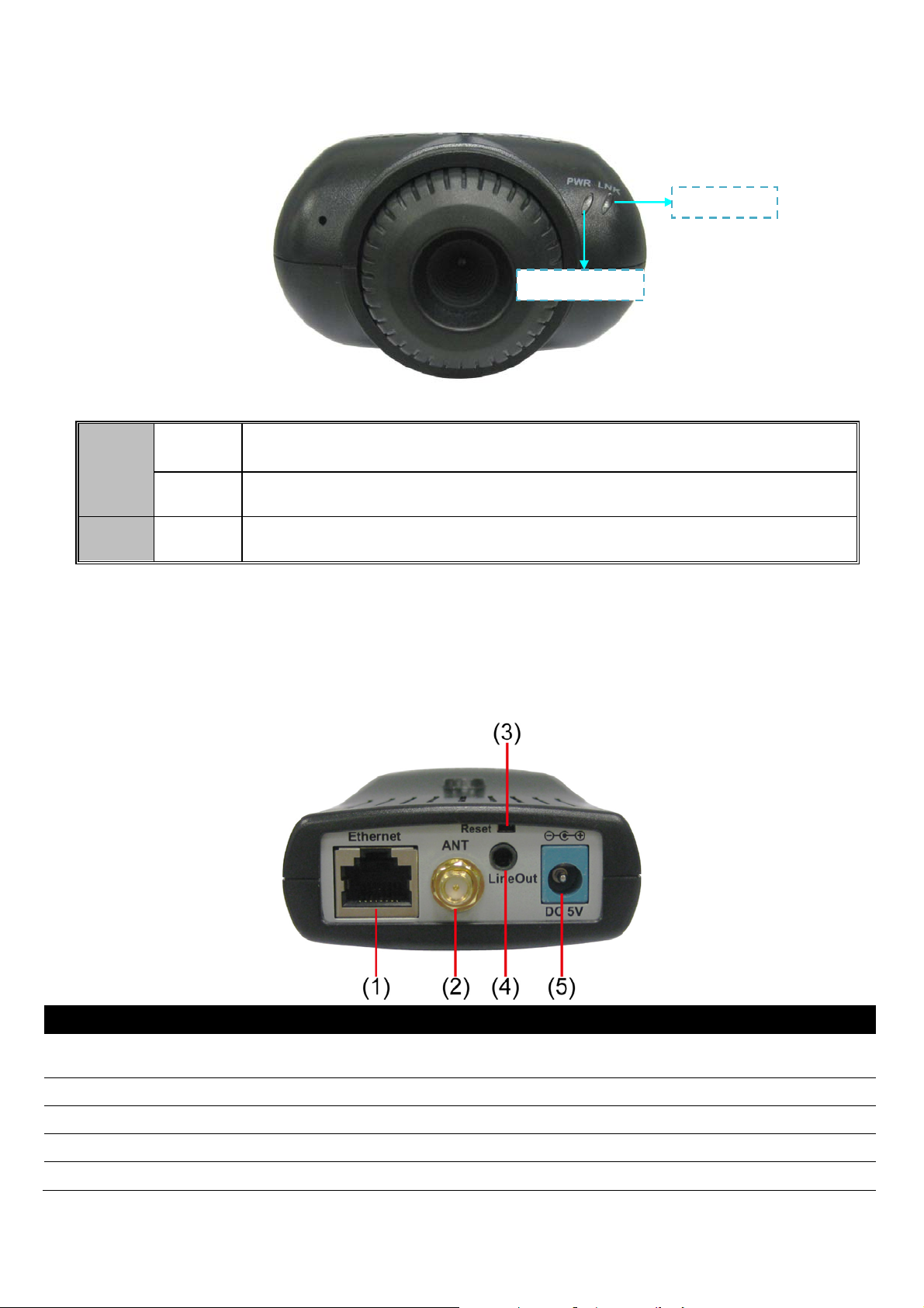
1.6.2 SF1301
Name Function
(1) Ethernet port For connecting to Ethernet LAN. The port is auto MDI-II/MDI-X and auto-negotiation for port
speed.
(2) Reset button Press to restore to the factory default setting.
(3) Audio line out For connecting the audio out device such as speaker.
(4) DC power For connecting the power adaptor.
5
Page 14
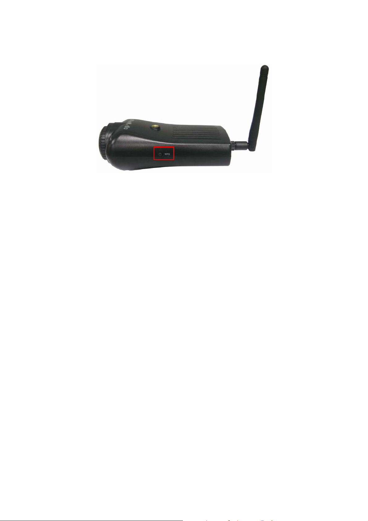
1.6.3 Using the WPS Button (Only SF1301W)
Wi-Fi Protected Setup (WPS) is a standard for easy and secure establishment of a wireless home network.
The wireless camera and AP (Access Point) device must both support WPS.
Please refer the following steps to enable WPS function:
1. Please make sure your Access Point (AP) device supports WPS function.
2. Pressing the WPS button of AP.
3. Press and hold the WPS button of IP camera until the power LED turns off (about 5 seconds), and then,
the LED will start to blink at every 2 seconds that means WPS function is set.
4. And then, wait about 120 seconds for WPS to be functional between AP and the IP camera.
5. According the power indicator can indicates the following status:
¾ Enable WPS Successful: power LED is lighting and IP camera will reboot automatically.
¾ Enable WPS Fail: power LED is blinking every 10 seconds until 120 seconds later, and then IP camera
will reboot automatically.
6. If WPS setup is failed, please re-do the above steps 2 to 4.
6
Page 15
Chapter 2 Installing the Camera
The camera is intended for indoor use. Therefore, the power adapter and power source should be protected
from water and moisture, excessive heat, direct sunlight and cold. Please make sure the power adapter and
cord and Ethernet cable are safely arranged so they do not create a tripping hazard and will not be disturbed
by people or objects moving past.
The camera can be attached to the stand that is included in the package. The camera stand can be mounted
on a flat surface through the three screw holes on the base of the stand.
Please refer the following description to install the camera.
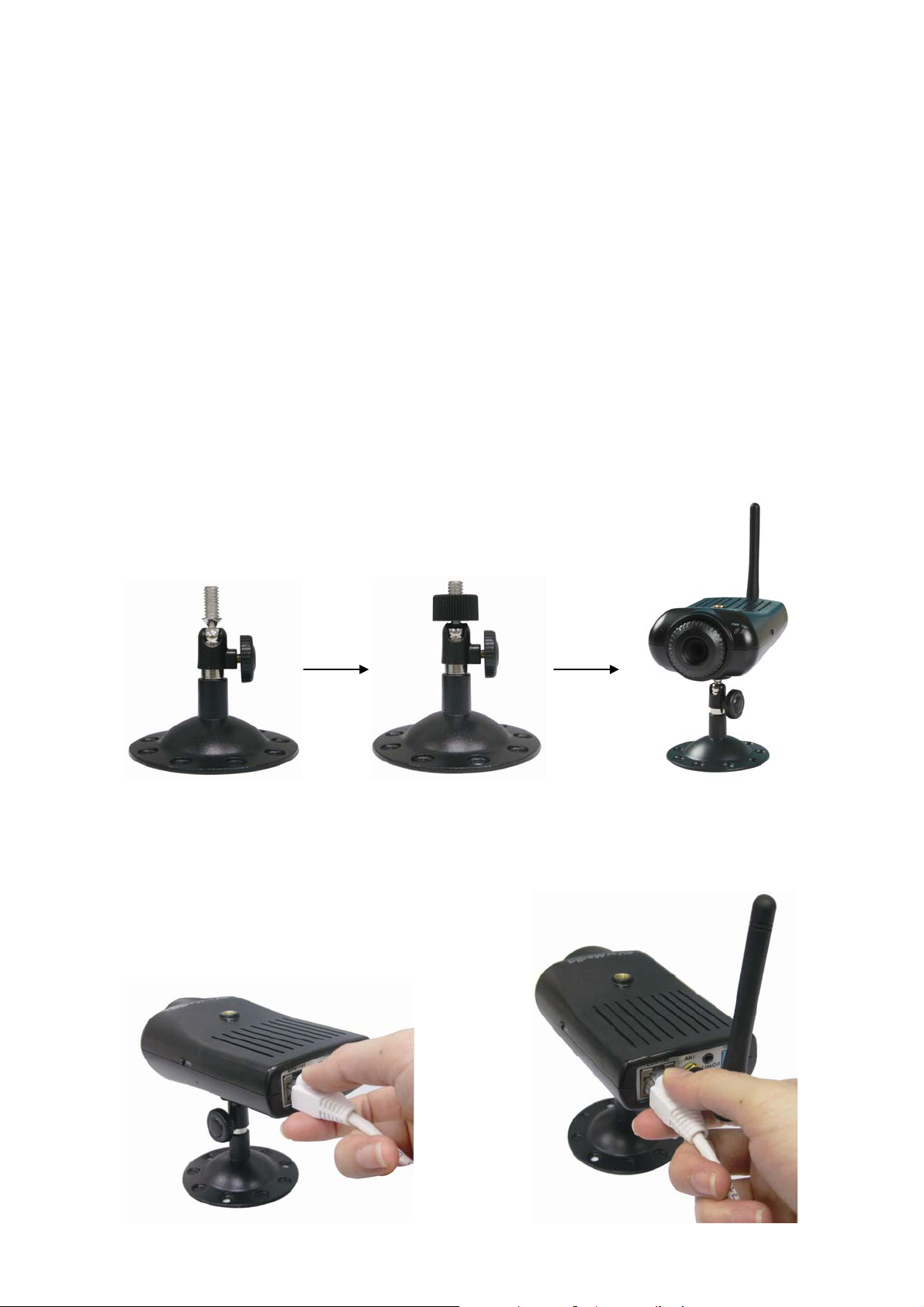
2.1 Attach Camera to the Stand
The IP camera comes with a camera stand, which has a swivel prop stand that can be attached to the
camera’s screw hole on the top/bottom.
1. Screw tight the swivel prop stand and screw the black nut on the swivel prop stand.
2. And then, attach the camera on the stand.
3. Lose the wheel can adjust the camera to the wanted position. Remember to tight the swivel prop stand
after adjusting.
4. To mount the camera, using the screws to secure the camera stand on the wall.
2.2 Connect Ethernet Cable
Plug-in the Ethernet cable into the Ethernet port that is located on the rear panel of the camera. Both wired
and wireless IP camera can be installed Ethernet cable.
SF1301 SF1301W
7
Page 16
2.3 Connect Power and Power On Camera
Connect the external power adapter to the DC power input connector located on the camera’s rear panel, and
then connect it to your wall outlet. You can confirm the power source is supplied from the Power LED on the
camera.
2.4 Reset Camera
To reset the system settings to factory defaults, please follow below steps:
1. Make sure the power status of camera is ON.
2. Press the reset button about 6 seconds.
3. And then, release the reset button.
4. The camera will automatically reboot. Upon restarting the camera loads the factory default configuration
settings.
8
Page 17
Chapter 3 Using the Camera Web Manager
The IP camera can be managed by using the web browser through the internet. It is recommended to check
and make sure the accessing of the IP camera before installing it at the location, especially if it is mounted to a
ceiling or other area that is difficult to physically access.
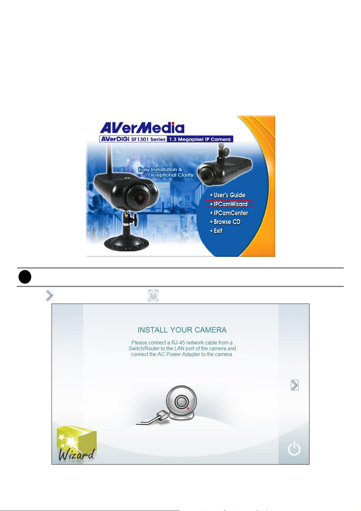
3.1 First Time to Use the IP Camera
For the first time, using the IPCamWizard to initialize the IP camera. Follow the below steps to initial the IP
camera:
1. Place the installation CD into the CD-ROM drive then click IPCamWizard to install it.
2. To run the IPCamWizard, click Start > Program > NetworkServeillance > IPCamWizard.
Please make sure the IP camera is installed on your network.
i
3. Click to go to next step. To exit, click .
9
Page 18
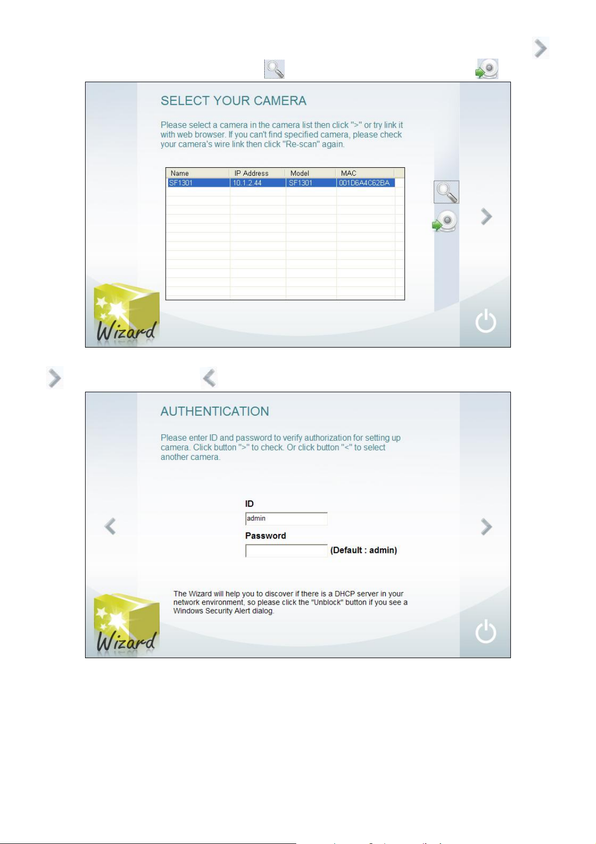
4. The detected IP cameras will be listed out. Select the camera that user wants to configure and click go
to next step. To refresh the camera list, click
5. Enter the
default is
ID(
admin)
and
Password(
. To link to the Live Video Viewer, click .
default is blank) of the camera for authentication verify. Click
to go to next step and click to go back previous page.
10
Page 19
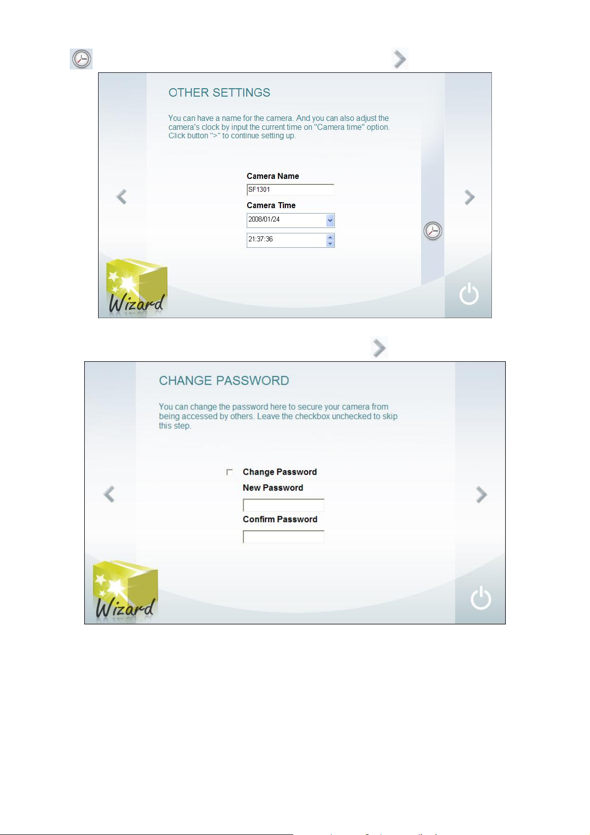
6. Assign a
click
Camera Name
to copy your PC’s system time to the camera. And then, click to go to next step.
to the camera. Select the correct
7. To change the authentication password. Mark
and
Date
Change Password
of the camera. User also can
Time
, and enter the
New Password
and re-
enter the password in
Confirm Password
column to confirm. Click
to go to next step.
11
Page 20
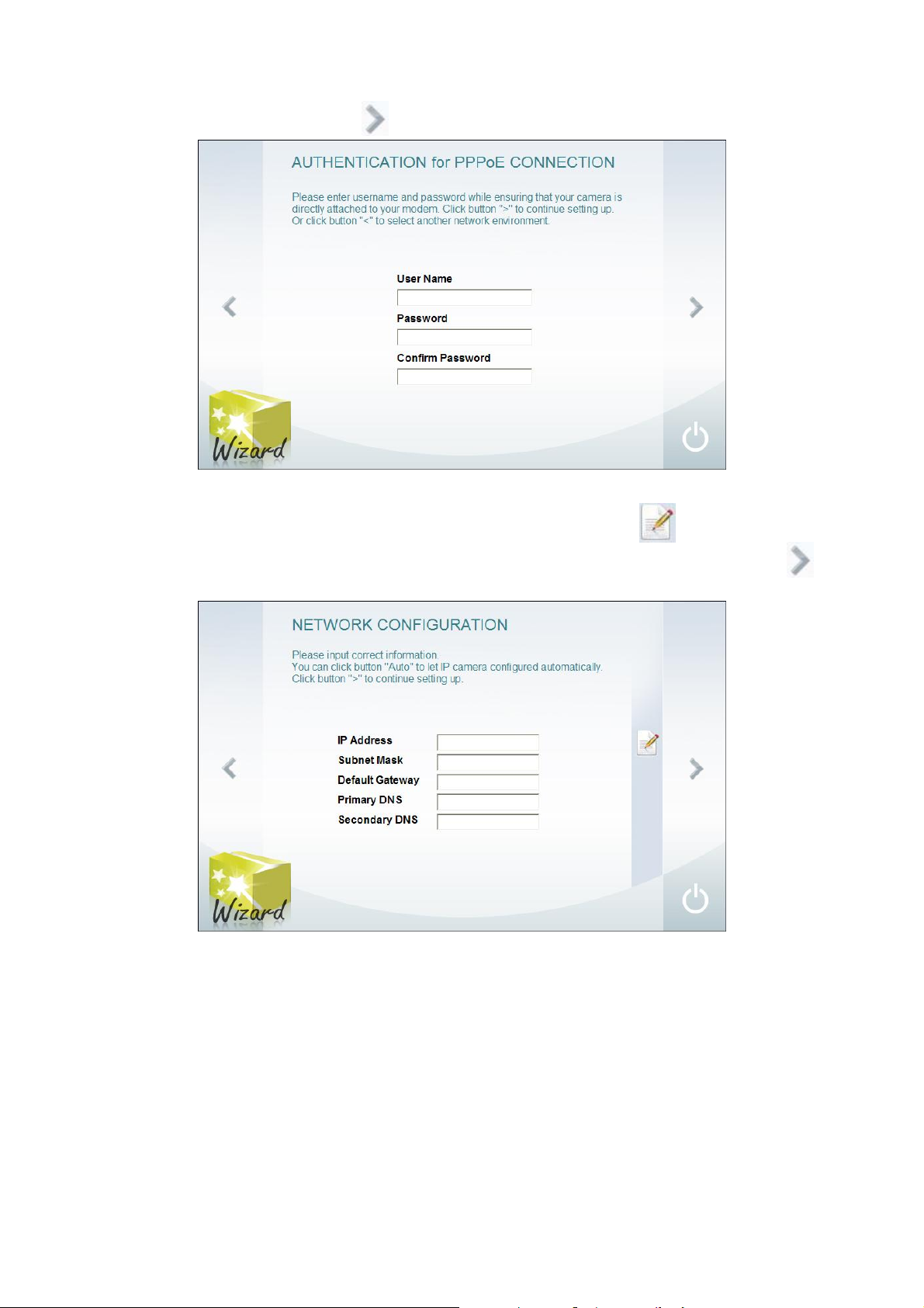
8. Select the type of network connection –
-
PPPoE:
For PPPoE client Internet access. Fill in the
for accessing authentication. Click
-
DHCP Connection:
Assign the IP address by local DHCP server to the camera.
PPPoE, DHCP, Fixed IP
User Name, Password
to go to next step.
.
, and
Confirm password
-
Static IP Address:
S
ubnet Mask, Default Gateway, Primary DNS
Assigns a constant IP address to the camera. Click
next step.
, and
Secondary DNS
to fill in the
IP Address
automatically. Click
,
to go to
12
Page 21
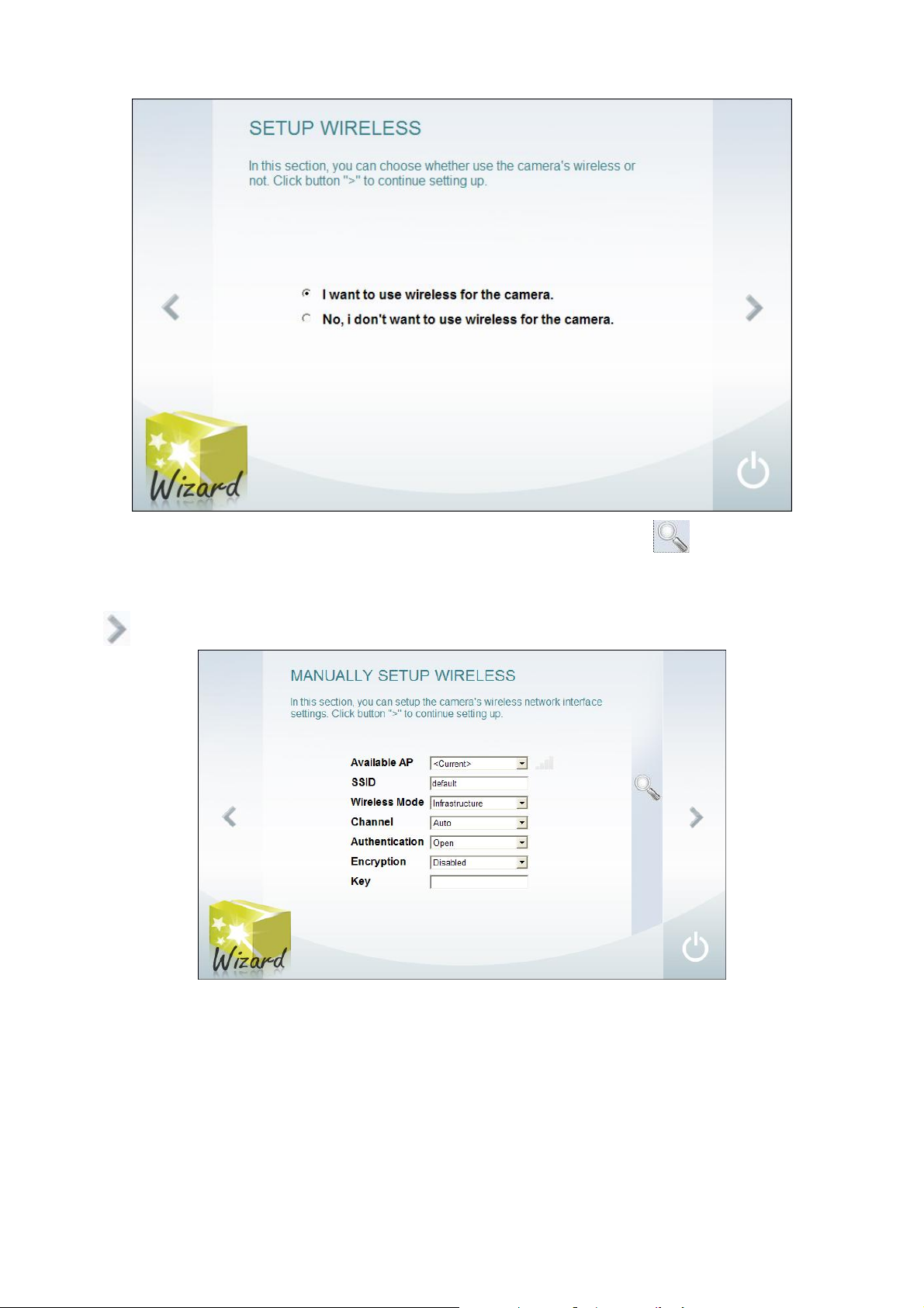
9. If your camera is a wireless camera, select the
the other option.
I want to use wireless for the camera
. Otherwise, select
- For wireless, select the AP that has been detected on the network. Click
Enter the
fields that are including
that is the name assign on AP. And then, select the related parameters in the following
SSID
Wireless Mode, Channel, Authentication, Encryption
can re-scan the AP.
and
Key
. The
Authentication, Encryption and Security Key depend on the type of security that you have used. Click
to go to next step.
13
Page 22

- For wired, view the information of the camera setting. Click to go to next step.
10. The configuration will be saved into the camera.
14
Page 23
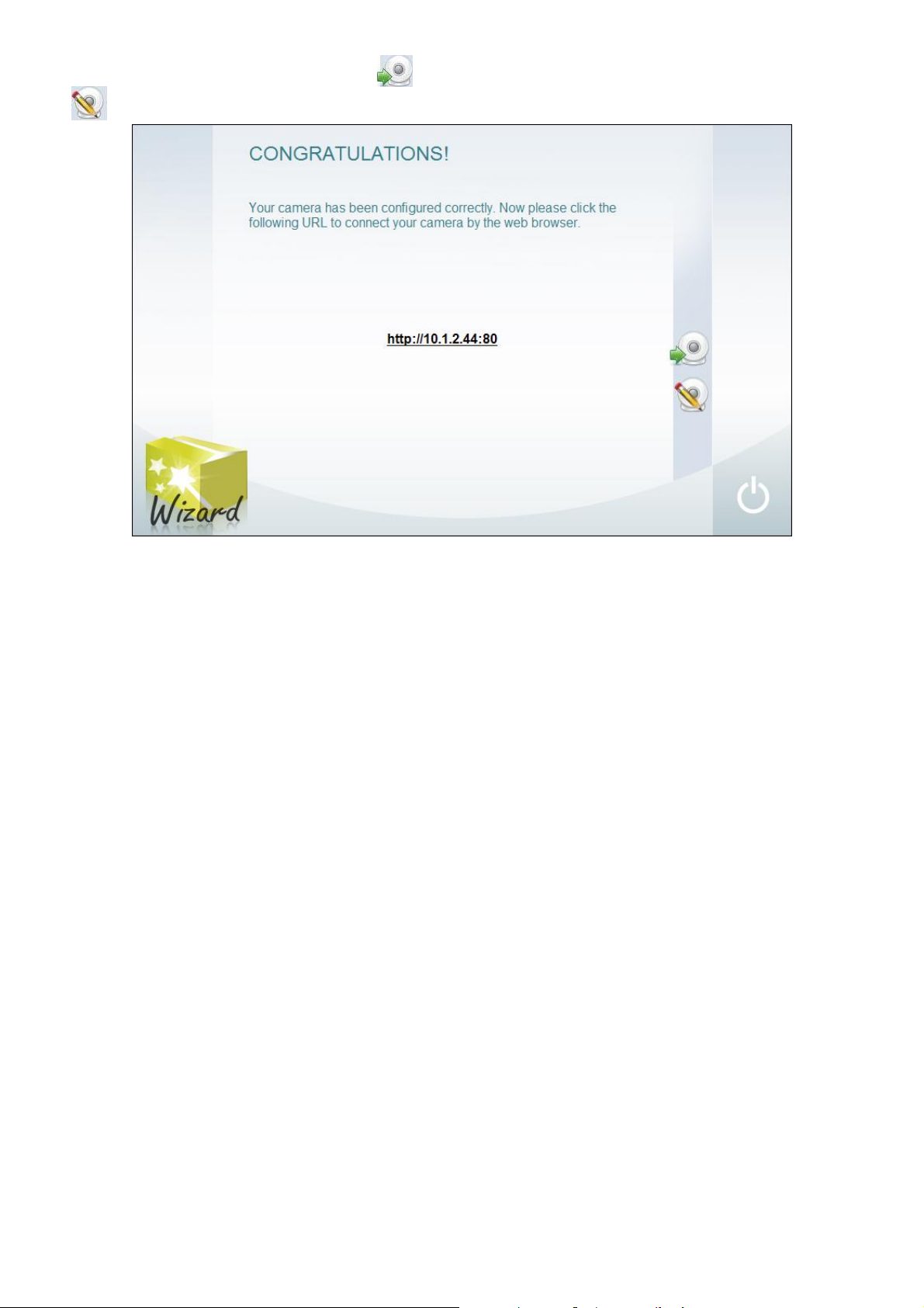
11. The setting is completed. User can click link to the Live Video Viewer. To setup another camera, click
.
15
Page 24

3.2 Familiarizing the Function Buttons in Live Video Viewer
On the IPCamWizard interface, select the IP camera that has been found on the network and click to
connect with IP camera. When authentication dialog show up, enter the ID(default is
Password
(default is no password) to login the camera.
admin
After connection has been made, the live video viewer will appear as following illustration shown.
) and
Name Function
(1) Camera Info Display current date, time, and name of camera.
(2) resolution mode
(3) Snapshot Capture a video image. The image will pop up in new windows. User may save the image to
(4) Record Recording the video
(5) Storage Path Set a storage path for saving recorded file. The default storage path is created when the Live
(6) Audio Enable/disable sound.
(7) 2-Way Talk Enable/disable 2-way audio function. This function allows the user site and camera site to
(8) Setup Setup the IP camera settings (see also Chapter 3.3).
Click the resolution buttons (
change depends on the
640 x 480, 30FPS, and MPGE4(default)
320 x 240, 30FPS, and MPGE4(default)
640 x480, 10FPS, and JPEG(default)
160 x 120, 5FPS, and MPGE4(default)
Full screen mode. Press ESC can switch back to the original display mode.
a local hard drive.
Video Viewer is activated.
talk via internet using MIC. Make sure your microphone and speakers work before using this
function.
Video and Audio Setting
~ )to view. The buttons of resolution values may
(see also Chapter 3.3.5
)
16
Page 25

Name Function
(9) System setup Configuring the camera system parameters(see also Chapter 3.4
(10) Live video Indicate the video is real-time.
(11) Motion detection The motion detection icon appears yellow when motion is detected. Motion detection must
be configured in the Motion Detection menu in the Setup section (see also Chapter 3.3.6
(12) Record indicator When recoding is activated, the REC icon will light up.
(13) Language Change the language of the menu interface and function tips.
)
).
17
Page 26

3.3 IP Camera Setup
Click to switch to IP camera setup menu that user can configure network settings, wireless, video
and other settings of the IP camera.
3.3.1 Setup Wizard
In Setup menu, user can follow the setup wizard to configure the camera in few and quick steps. Click Next to
start configuring.
STEP 1: SETUP LAN SETTINGS
Configure the IP setting of the IP camera.
DHCP Connection: Assign the IP address by local DHCP server to the IP camera.
Static IP Address: Assigns a constant IP address to the IP camera. Fill in IP Address, Subnet Mask,
Default Gateway, Primary DNS, and Secondary DNS and click Next to go next step.
18
Page 27

STEP 2: SETUP INTERNET SETTINGS
If your ISP require connection authentication, mark Enable and enter the User Name and Password that
your ISP provides to you. Click Next to go the next steps.
STEP 3: SETUP DDNS SETTINGS
Dynamic Domain Name Service is a data query service mainly used on the Internet for translating domain
names into IP addresses.
Mark Enable and enter Server Address of DNS or select from drop-down list, Host Name, User Name,
Password, and Verify Password. Click Next to go to next step.
19
Page 28
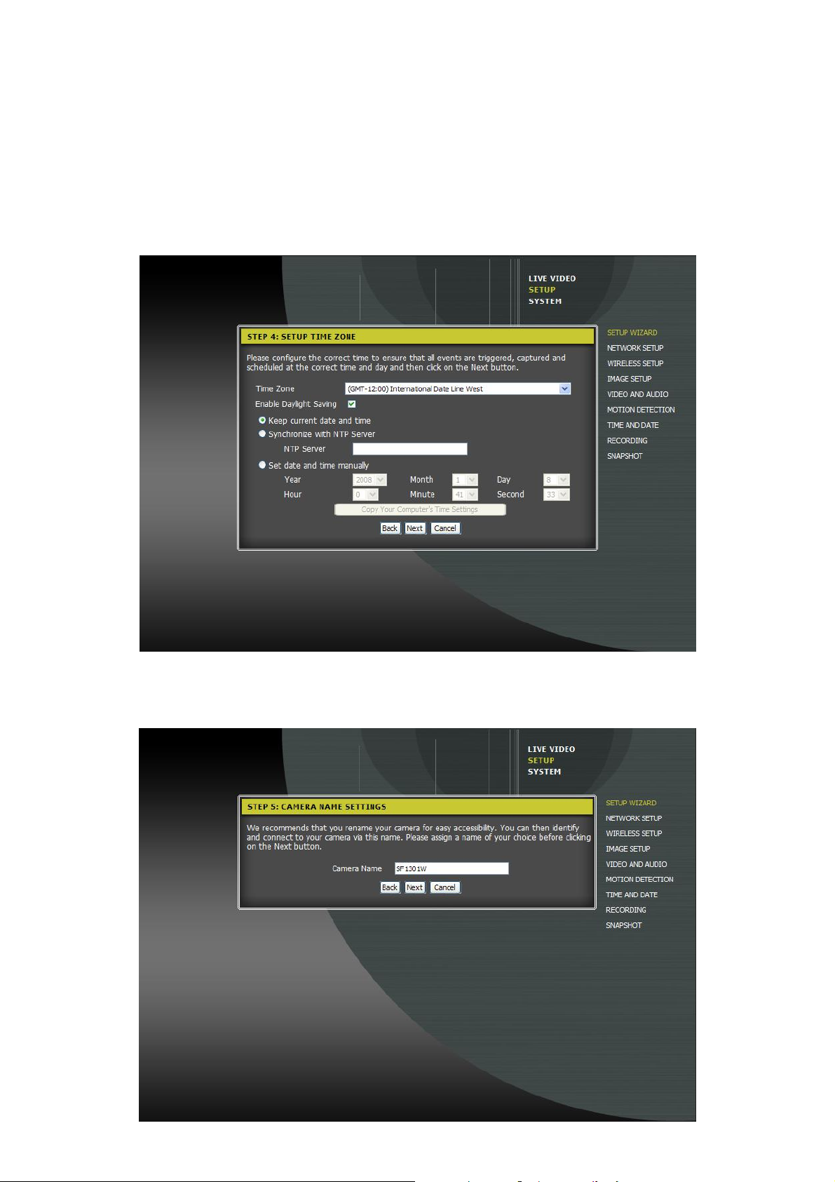
STEP 4: SETUP TIME ZONE
Setup the system time of the camera. Click Next to go to next step.
Time Zone: Select the time zone that IP camera is located.
Enable Daylight Saving: Enable/disable daylight saving function if the time zone that camera is
located has daylight saving time.
Keep current date and time: The time will be user has been setup.
Synchronize with NTP Server: To adjust the time by NTP server that user has setup.
Set date and time manually: To adjust the date and time manually. Select the Year, Month, Day,
Hour, Minute, and Second from drop-down list. Or click Copy Your Computer’s Time Settings to
get the date and time setting directly from your PC.
STEP 5: CAMERA NAME SETTINGS
Give a name to the IP camera. Default is model name of the IP camera. Click Next to complete the setup
process.
20
Page 29

STEP6: SETUP COMPLETE
Click Apply to save the configuration. To go back to last step, click Back. Click Cancel will back to the
step 1 of Setup Wizard.
21
Page 30

3.3.2 Network Settings
Click the Network Setup to configure IP settings, PPPoE, DDNS and HTTP or RTSP port. Click Save to save
the settings and click Cancel to exit without save.
3.3.2.1 NETWORK SETTINGS
The IP address of the camera can be assigned by local DHCP server automatically or assign a static IP
address as needed for the private network.
DHCP Connection: Assign the IP address by local DHCP server to the camera.
Static IP Address: Assigns a constant IP address to the camera. Fill in IP Address, Subnet Mask, and
Default Gateway, Primary DNS, and Secondary DNS.
Enable UPnP: To allow Windows base PCs to find this camera under Network Neighborhood without
configuration.
Enable UPnP port forwarding: To allow the camera to add a port forwarding entry into network router
automatically when checked, if network router supports UPnP port forwarding.
External HTTP port: Set a HTTP port for UPnP port forwarding.
External RTSP port: Set a RTSP port for UPnP port forwarding.
Port forwarding/mapping must be enabled on Network router/gateway for remote viewing of camera
i
video via the internet. Please refer to the user’s manual of router to enable port forwarding/mapping
function.
22
Page 31

Enable PPPoE: For PPPoE client Internet access. Fill in the User Name, Password, and Confirm
password for accessing authentication.
3.3.2.2 DYNAMIC DNS SETTING
Dynamic Domain Name Service is a data query service mainly used on the Internet for translating domain
names into IP address. If ISP provider assigns dynamic IP for every time user make connection, enable DDNS
service and the IP camera will update IP address automatically to DDNS server when the IP camera get a
different IP address.
Mark Enable and enter Server Address of DNS or select from drop-down list, Host Name, User Name,
Password, and Verify Password. Enter a time period of connection with DNS server in Timeout(hours)
column.
23
Page 32

3.3.2.3 PORT DETAIL SETTINGS
To configure the HTTP port for web access and RTSP port for mobile access. Enable User authentication to
require the access authentication.
24
Page 33

3.3.3 Wireless Setup
The Wireless IP Camera supports 802.11g protocol that is including WEP or WPA basic security settings. The
wireless camera also supports WPS (Wi-Fi Protected Setup) for quick and easy wireless security setup. Click
Save to complete the configuration, Cancel to discard the setting.
Enable Wireless: Mark to enable wireless function.
Site Survey: When wireless function is enabled, the camera system will automatically scan the available
wireless AP devices on the network. Select the wireless AP from drop-down list to connect. When user
selects the wireless AP device, the degree of signal will be display at bottom of the screen. Click Rescan
to search available AP devices again.
SSID: SSID (Service Set Identity) is the ID assigned to the wireless AP(Access Point). The camera
system will auto-detect and display the SSID of wireless AP.
Wireless Mode: Select the Infrastructure (default) as the wireless mode. If your network is using a
network connection directly between the devices without wireless AP, and then, select the Ad-Hoc as the
wireless mode.
Channel: Select the channel for communicate with the wireless AP or select Auto. Then channel
selection is depending on the regulatory region where the AP device is sold.
Authentication: Select the type of authentication that user has used on the network - Open, Shared,
WPA-PSK, or WPA2-PSK.
25
Page 34
Encryption: If select WPA-PSK or WPA2-PSK authentication, user needs to specify whether the
wireless network uses TKIP or AES encryption. If select Open or Shared authentication, the setting will
be automatically set.
Key: For WEP, WPA-PSK, or WPA2-PSK authentication, enter the Key (also known as password) used
for the wireless network.
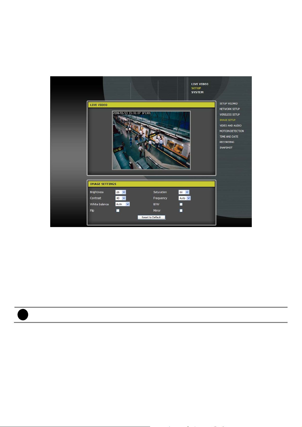
3.3.4 Image Setup
To adjust the brightness, saturation, contrast, frequency, and white balance of the image.
Video image settings
Brightness/ Saturation/Contrast/Frequency/White Balance
From drop-down list select the value that user wants. User can preview the adjusted image from Live Video
windows. Click Reset to Default can set all adjustment back to factory default setting.
Flip
Enable to turn the image upside down.
B/W
Change the image to black and white color.
Mirror
Flip the image in horizontally direction.
The Flip and Mirror can be used when the camera is hanging on the celling upside down.
i
26
Page 35

3.3.5 Video and Audio Settings
To setup resolution, encode FPS, bps, JPEG quality, and RTSP URL of video output. The video setting is
related to the resolution buttons on the Live Video Viewer (see also Chapter 3.2
setting. The camera will reboot automatically when the setting is changed.
) .Click Save to change the
Video Sensor: Set the camera's sensor output to VGA quality (640x640), XGA quality (1024x768), or
SXGA quality (1280x1024).
27
Page 36

When using SXGA mode, motion detection and motion triggered will be disabled.
i
Profile 1:
UI. All the value settings are related to the
- Encode Type: select encode type of video – MPEG4 or JPEG.
- Resolution: Available resolutions are related to Sensor Output and Encode Type. For 1280 x 1024
resolution, please select SXGA and JPEG encode type.
Setup the video setting of resolution button (
Sensor Output
) 1 which is located on the Live Video Viewer
that user has chosen.
i
- FPS: Select the frame rate.
- bps: Select the bit rate per second. Only when encode type is MPEG4, the bps can be setup.
- JPEG Quality: Select the quality of video. Only when encode type is JPEG, the JPEG quality can be
selected.
- RTSP URL: Enter the URL for RTSP connection.
Profile 2:
UI. All the value settings are related to the
- Encode Type: select encode type of video – MPEG4 or JPEG.
- Resolution: Available resolutions are related to Sensor Output and Encode Type.
- FPS: Select the frame rate.
- bps: Select the bit rate per second. Only when encode type is MPEG4, the bps can be setup.
- JPEG Quality: Select the quality of video. Only when encode type is JPEG, the JPEG quality can be
selected.
- RTSP URL: Enter the URL for RTSP connection.
Profile 3:
UI. All the value settings are related to the
Only SXGA sensor output supports 1280 x 1024 resolution at Profile 1.
Setup the video setting of resolution button (
Sensor Output
Setup the video setting of resolution button (
Sensor Output
) 2 which is located on the Live Video Viewer
that user has chosen.
) 3 which is located on the Live Video Viewer
that user has chosen.
- Encode Type: Only support JPEG.
- Resolution: Available resolutions are related to Sensor Output.
- FPS: Select the frame rate.
- JPEG Quality: Select the quality of video.
28
Page 37

- RTSP URL: Enter the URL for RTSP connection.
Video Profile 4 for Mobile Device Only:
located on the Live Video Viewer UI. Profile 4 is the video setting for mobile accessing. All the value
settings are related to the
- Encode Type: Only support MPEG4.
- Resolution: Available resolutions are related to Sensor Output.
- FPS: Select the frame rate.
- bps: Select the bit rate per second. Only when encode type is MPEG4, the bps can be setup.
- RTSP URL: Enter the URL for RTSP connection.
Higher frame rate and bit rate provide better video quality but require more network bandwidth.
i
Night Mode:
Audio Setup:
- Enable Speaker: Enable to output audio to an external speaker that is attached to the external speaker
jack of the camera. This allows user to talk with another person through the camera.
- Volume: Set the volume level of the external speaker.
- Enable Microphone: Enable to hear the audio receive by the camera’s microphone. This allows user
to hear what is happening near the camera.
- Volume: Set the volume level of the audio.
When in low light situations, enable the
Sensor Output
Setup the video setting of resolution button (
that user has chosen.
Night Mode
.
) 4 which is
29
Page 38

3.3.6 Motion Detection
Start recording the video from the selected area only when the camera detects movement. Mark Enable Video
Motion to enable motion detection. Select Draw motion area and drag to select the area of motion detection.
The selected area will appear a red box. To clear the selected area, select Erase motion area and drag on
the selected area to clear. To clear all selected motion detected area, click Clear button. To adjust Sensitivity,
enter the value 0 ~ 100. The higher the value, the finer the sensitivity is detected. Click Save to complete the
setup.
30
Page 39

3.3.7 Time and Date
To configure, update, and maintain the correct time on the internal system clock.
Time Configuration
- Time Zone: Select the time zone that the camera is located.
- Enable Daylight Saving: If it is during Daylight Saving period, enable Daylight Saving function.
¾ Auto Daylight Saving: Select to adjust Daylight Saving Time automatically.
¾ Set date and time manually: Mark check box to enable daylight saving. And then, select the Start
and End Time from drop-down list.
¾ Offset: Assign a time that it is for daylight saving time offset in your time zone. For example: if the
time zone is in U.S. Eastern, the time offset is 1 hour.
Automatic Time Configuration
- Synchronize with NTP Server: Enable to synchronize the camera time from NTP server.
- NTP Server: Enter the NTP server IP or URL for camera time synchronizes.
- Set date and time manually: Enable to set the time and date manually. Select the present Year,
Month, Day, Hour, Minute, and Second. User can also click the Copy Your Computer's Time
Settings button to automatically fill in with the present time and date from your computer.
31
Page 40

3.3.8 Recording Setup
To setup recording related parameters.
Enable recording: Enable the recording function. After enabling recording, user needs to select a
location to save the recorded data, setup record mode and record schedule.
If the recording is not enabled, the recording button that is located on Live Video Viewer UI will not
i
functional.
- Record to:
¾ Samba network drive: Saving the record data on your network storage server.
¾ Samba Auth: Select Anonymous if user name or password is not required for accessing the
Samba drive. If user name and password is required, select the Account and fill in the User name,
Password, and Password confirm.
¾ Server: Enter the name of the server the Samba drive.
¾ Shared Folder: Enter the path of the shared folder.
- Recording Options
¾ Resolution: Select the resolution of the recording video. Those resolutions are set in Video and
Audio section.
¾ Record until: Setup a minimum buffer space of hard disk capacity. It is suggested set at least
32MB for buffer space.
¾ When storage is full: When the storage capacity is full or has reached the space limit that is
specified in Record until, user can choose to Stop recording or select Overwrite older
recordings to delete old recordings.
Recording Method
- Event Based: Enable to record video when motion detected event happen.
¾ Motion detection triggered recording: Enable to record video when motion is detected.
¾ Prerecord: Setup how many seconds of video before the event happen will be recorded.
¾ Postrecord: Setup how many seconds of video after the event happen will be recorded. For
example: Set the Prerecord to 5 seconds and Postrecord to 9 seconds, the camera will save
video from 5 seconds before motion was detected to 9 seconds after motion was detected.
- Continuous: Enable the camera to record continuously.
- Scheduled: Enable the camera to automatically record video during the specified times. Enable the
day (Sun ~ Mon) and select the start time and end time.
32
Page 41

33
Page 42

3.3.9 Snapshot Setup
Set the camera to take snapshots when motion is detected. Snapshots image can be sent to an e-mail
address and an FTP server. Click Save to save the settings.
The resolution of the snapshot image is based on Profile 3 that user has setup in Video and Audio
i
section.
Enable Snapshot: Mark to enable the snapshot function.
- Scheduling: Select the condition to trigger the snapshot.
¾ Event Based: The condition to trigger the snapshot is based on the selected event.
9 Motion detection: The camera to take a snapshot when the motion is detected.
If the camera is set to SXGA mode in Audio and Video, motion detection snapshots is
i
disabled.
¾ Continuous (FTP only): The snapshot image will be taken continuing. The snapshot image is
taken under Continuous condition only can send to FTP server, not by e-mail.
¾ Scheduled (FTP only): The snapshot image will can be taken during the selected day and time
period. Mark the Day (Sun~Mon) and select the start and end time. The snapshot image is taken
under Scheduled condition only can send to FTP server, not by e-mail.
Send to: Setting the e-mail address to send the snapshot image. Click Test to check if the e-mail setting
is workable.
- E-mail Address: Enable to send the snapshot image to the specific e-mail address.
¾ User Name: Enter the username or login name for your e-mail account.
¾ Password: Enter the password for your e-mail account.
¾ SMTP Mail Server: Enter the SMTP server of your e-mail account.
¾ Sender E-mail Address: Enter the sender’s e-mail address.
¾ Recipient E-mail Address: Enter the e-mail address that user wants to send the snapshot image
FTP Server: Enable to send the snapshots image to the specified FTP server. If you do not know what
information to enter, contact the administrator of the FTP server for details. Click Test to check if the FTP
setting is correct.
¾ User Name: Enter the user name of your FTP account.
¾ Password: Enter the password of your FTP account.
¾ Host Name: Enter the host name of your FTP account.
¾ Path: Enter the storage path on the FTP server that user wants to save the snapshots image.
¾ Prefix Filename: Enter the text word that user wants to attach to the snapshot image file name.
¾ Port: Enter the port used by the FTP server.
¾ Interval: Set a time gap for sending snapshot image to the FTP server. For example: The interval
¾ Passive Mode: If the FTP server requires using the passive mode, mark the check box to enable it.
to.
time is 10 second, and then every 10 seconds will send a snapshot image to the FTP server.
34
Page 43

35
Page 44

3.4 System Configuration
Click from Live Video Viewer UI or click
menu.
SYSTEM
from Setup menu to switch to the camera system
36
Page 45
3.4.1 Device Management
In Device Management section, user can change administrator’s password, create and manage user account,
and modify name of camera.
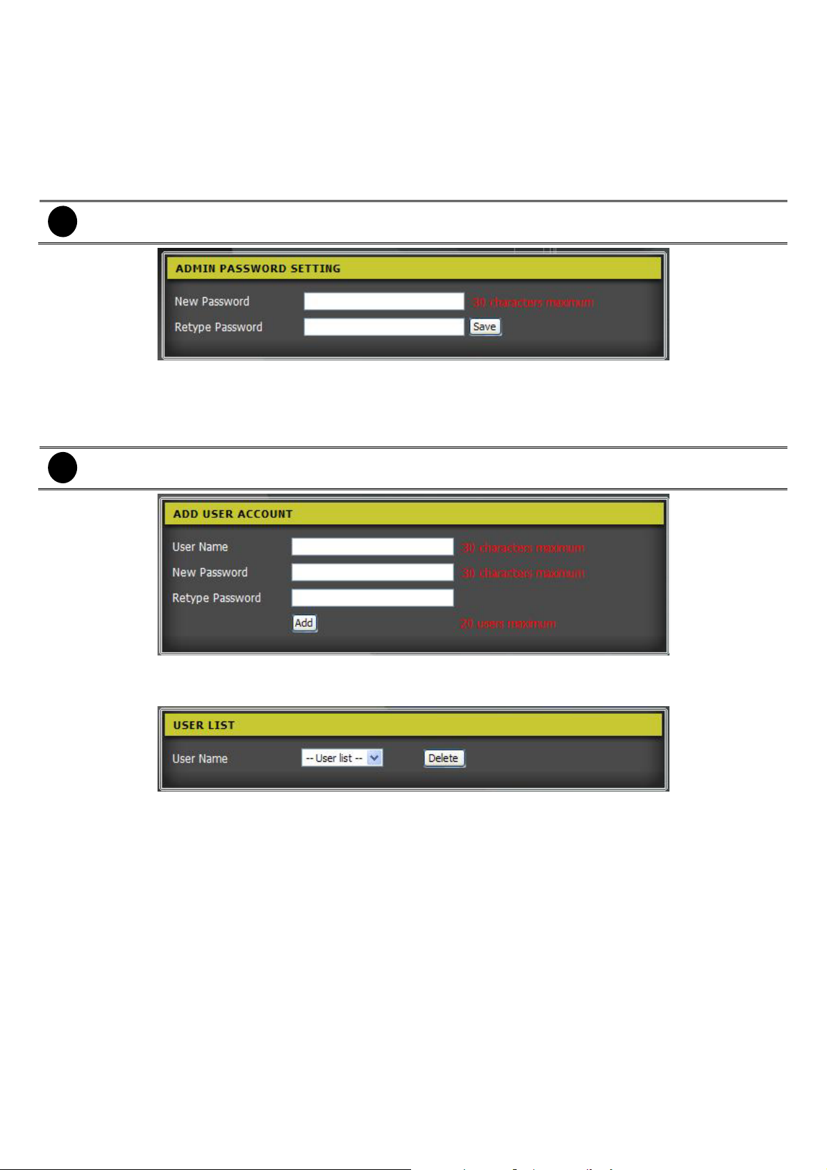
Admin Password Setting: User can change the password of admin account. For the security issue, we
do strongly recommend that user changes the admin’s password periodically. To change the password,
enter the new password in New Password column and re-enter the new password again in Retype
Password column. And then, click Save to complete the password changing.
The password length maximum is 30 characters.
i
Add User Account: Creat the user account beside the admin account. User account only allow to view
the live video, no authority of camera system setting. Enter the name of user account in User Name
column, enter the password in New Password column, and enter the password again in Retype
Password coulumn. And then, click Add to create the user account.
- The user name and password length maximum is 30 characters.
i
- The user account maximum is 20 accounts.
User List: To delete the un-wanted user account. Select the user account from drop-down list and click
Delete to delete the account.
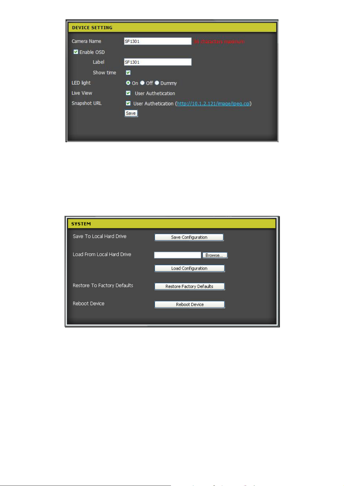
Device Setting: Configure parameters of the camera.
- Camera Name: Give a name to the camera. The default name is camera model name.
¾ Enable OSD: Enable/disable the label text and time display on Live Video Viewer UI.
9 Label: Enter the short name/description that will display on the Live Video Viewer UI.
9 Show time: Enable/disable to display the camera system time on the Live Video Viewer UI.
¾ LED light: Select the LED indicator status – On, Off, or Dummy.
¾ Live View: Enable/disable authentication when remote accessing the camera for viewing live video.
¾ Snapshot URL: Enable/disable authentication when remote accessing the camera for viewing
snapshot image.
37
Page 46
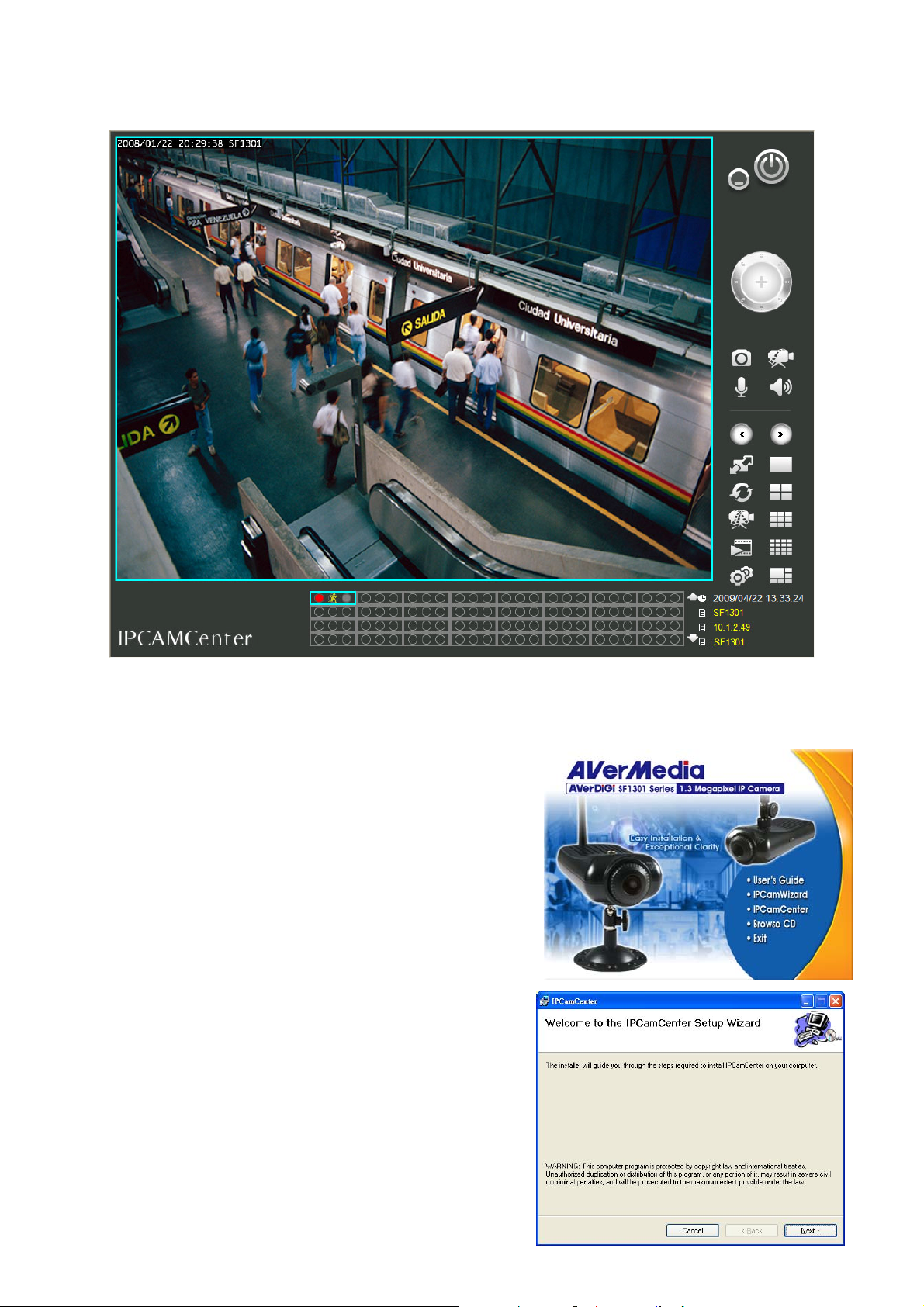
3.4.2 Backup and Restore Setup
Save to Local Hard Drive: Save the camera configuration to the locate hard disk. Click Save
Configuration and the configuration will be save in *.db format.
Load From Local Hard Drive: Reload the configuration file that user has saved on local hard disk before
back to the camera system.
Restore To Factory Defaults: Set the camera system back to the factory default settings.
Reboot Device: Click to restart the camera system.
38
Page 47

3.4.3 Firmware Upgrade
To upgrade the camera firmware. Please make sure the correct firmware file is located on the PC. Click the
Browse to locate the file, and then click the Upload to load the file. After firmware updated, the camera will
restart automatically.
39
Page 48

3.4.4 Device Information
Display the camera information such as camera name, time, firmware version, and network settings.
3.4.5 Camera Log
To view the camera’s current log. To save the log in *.text format on the local hard disk, click the Download
button. Click Clear to delete all logs.
40
Page 49
Chapter 4 IPCamCenter
IPCamCenter can view multiple cameras’ live view. Also, IPCamCenter can configure the camera one by one.
4.1 Install the IPCamCenter
Follow the below steps to install the IPCamWizard:
1. Insert the Installation CD into the CD-ROM drive on the PC.
Click IPCamCenter to install.
2. Click Next.
41
Page 50
3. Read the license agreement and click Yes to accept the
agreement.
4. Click Next to continue the installation if user doesn’t want to
change the installation direction. To change the install direction,
click Browse... and locate the new direction.
5. Click Nex to continue the installation.
6. Click the Close to complete the installation.
42
Page 51

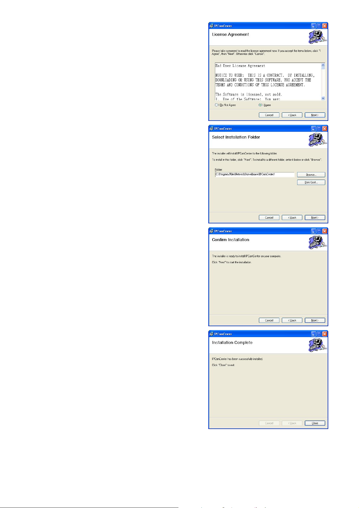
4.2 Using the IPCamCenter
The IPCamCenter can connect with multiple cameras to view the camera live video. Also, user can configure
the monitor camera through the IPCamWizard. To run the application, click Start > Programs >
NetworkSurveillance > IPCamCenter > IPCamCenter.
4.2.1 To Connect the Camera
1. When the first time to run the
2. User also can click the
n
IPCamCenter
button on IPCamCenter UI and click
, the
Add camera for monitoring
Add camera in local LAN
windows will popup.
.
o
p
3. The IPCamCenter will auto detect the IP camera on the network. To add the camera, select the camera,
enter the
will be added and user should see the live video on preview screen. To search the camera again, click
Refresh
4. If user wants to change the IP address of camera, click
Administrator’s id
the camera. Select the type of IP (
if necessary. Click OK to complete the change.
Username
.
and
password
and
Password
of the camera, and click
Change the camera’s IP
. Only
DHCP
Administrator
or
Fixed IP
) and fill in the new IP address and relate parameters
OK, add this camera
has the authority can change the IP address of
. The selected camera
and enter the
43
Page 52

5. User also can enter the
camera for monitoring windows. User also can
by IP/URL
6. To add a camera, enter the
of the camera, and click
the live video on preview screen. Click
.
IP/URL
OK, add this camera
of the camera directly. Click
IP Address/URL of the camera, Port
n
o
Preview
Input the location of camera
click
. The selected camera will be added and user should see
can refresh the video of the camera.
from IPCamCenter UI and click
number, the
Username
from Add
Add camera
and
password
p
7. Click Exit when finish the camera adding.
q
44
Page 53

4.2.2 Familiarizing the Buttons in the IPCamCenter
To run the application, click Start > Programs > Netw orkSurveillance > IPCamCenter >IPCamCenter. The
main UI will appear as below shown:
Name Function
(1) Preview screen Display live video of the camera. Right-click on the channel will call out the short-cut menu.
45
Page 54

Name Function
(2) Channel status table Display the channel’s status information. Use ×Ø can scroll up and down the channel
status table.
When camera is connected, the record, motion, and GP status will be indicated by figure
icon.
Recording Status:
- Light up: Recording ON
- Light Off: Recording OFF
Motion Detection:
- Light up: ON
- Light Off: Disable
(3) Channel Info
(4) Configuration To add/delete the camera, setup the recording schedule, motion detection, and other
(5) Split screen mode Click to select the split screen mode – 6, 8, 13, 16, 17, 25, 28, 36, 49, 64-split screen mode.
(6) Playback
(7) 9-split screen mode Switch to 9-split screen mode.
(8) Record All
(9) QUAD screen mode Switch to 4-split screen mode
(10) Auto Scan
Display the name, IP address, model of selected channel and current date and time that
user has selected from
related parameters of the camera(see also Chapter 4.3)
Using the ÂÁ to go next or previous page.
Click to call out the IP Player to playback the recorded file by IPCamCenter(see also
Chapter 4.4
Click to enable recording for all channels. When the recording is enabled, the recording
status light of the channel will turn ON.
Start/Stop video screen cycle switch
)
(2) Channel status table
.
GP Input:
- Light up: YES
- Light Off: NO
(11) Single screen mode Switch to single camera mode.
(12) Full screen
(13) Speaker
(14) Audio ON/OFF
(15) Record
(16) Snapshot
(17) PTZ control
(18) Minimize Click to close the IPCamCenter to the system tray.
(19) Exit Close the IPCamCenter application.
Use the entire area of the screen to only display the video. To return, press ESC on the
keyboard.
Enable/disable speaker.
Click to turn on/off the audio sound play.
Enable/disable recording of the selected channel. When the recording is enabled, the
recoding status light of the channel will turn ON.
Capture the current video screen.
When the camera is a PTZ camera, use the PTZ control to move the lens of the camera.
46
Page 55

4.3 System Configuration
Click from IPCamCenter UI, user can connect the cameras; configure connected cameras, recording
settings, motion setting and other parameters.
SF1301
47
Page 56

4.3.1 Camera Management
User can add a camera connection, delete the camera, and configure the selected camera through the Web
configuration. To add a camera connection, please refer to Chapter 4.2.2
To using Web Configuration, select the camera from Camera List windows and click Web Configuration. The
Web configuration will appear. For detail of web configuration, please refer to Chapter 3.2
To configure the camera, select the camera from camera list and click Refresh to get camera information. The
selected camera information will display on Details of selected camera section. Mark the Enable live
preview to view the live video of the selected camera. User can modify the Port number, Live profile,
Record profile, and Memo, and then, click Modify to update the changes.
SF1301
.
.
48
Page 57

4.3.2 Camera Setting
Configure schedule recording and setup motion detection of the camera. Click >
enter the configuration interface.
Camera Setting
to
4.3.2.1 Setup the Schedule Recording
In Camera Setting, user can enable schedule recording that IPCamCenter will refer to the schedule that user
has setup to record the video from monitored cameras.
1. Click
2. Mark the
3. Select the schedule type –
-
Always:
-
Schedule:
4. To setup record schedule, click
5. Click
>
Camera settings
Enable schedule recording
Always
Continuing recording until user stop recording while the IPCamCenter is running.
To recording base on the schedule that user has setup.
Create template
to setup the record schedule.
or
Select
Schedule
.
6. There are two types of scheduling mode --
both exist.
Date mode
49
and
Week mode
. Two scheduling modes can be
Page 58

7. To setup
Date Mode
(click and select the date), and then click
8. To setup
day
Week Mode
(Sun ~ Sat or All) and click
schedule, enter the
schedule, select
Add
Week mode
. The week date schedule will added into the schedule profile.
Profile name
. The date schedule will be added into the schedule profile.
Add
9. Click OK to save the recording schedule settings.
10. To delete the schedule, select the schedule and click
as the schedule name and set the
. And then, setup the
Delete
.
Start time, End time
From
, and
and To
Week
11. After setup the recording schedule, user should see all setup schedules in
12. User must select the schedule in order to activate the schedule. Click the
13. In Camera setup windows, click
selected schedule to all cameras, click
Apply
to complete the schedule record setting. If user wants to use the
Apply to all cameras
.
14. Click OK to exit the configuration interface.
50
Select template
to add the select schedule.
Add
windows.
Page 59

51
Page 60
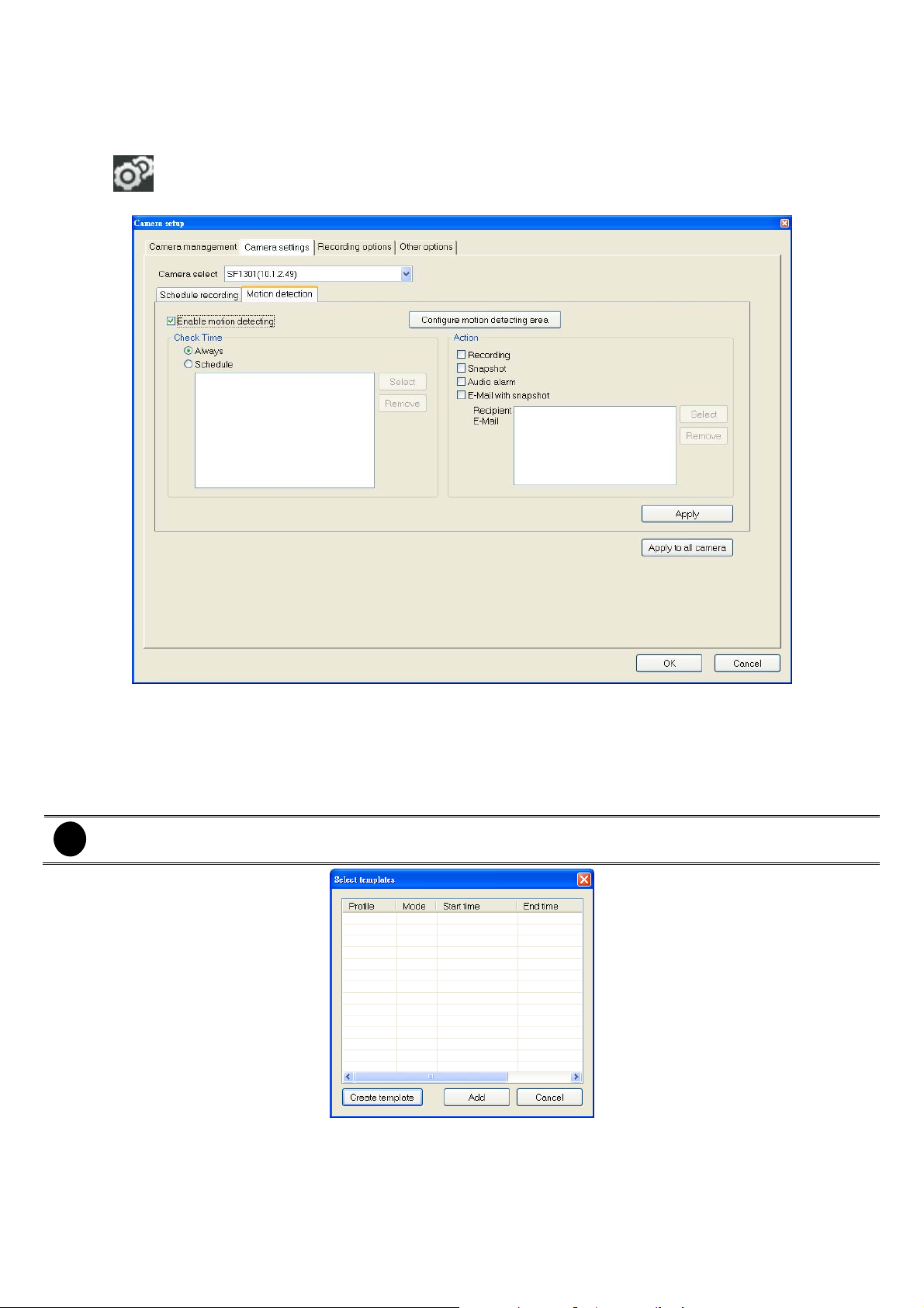
4.3.2.2 Setup the Motion Detection
Setting schedule, area and action of the motion detection.
A. Enable motion detection
1. Click
2. Mark Enable motion detecting to enable motion detection.
>
Camera settings > Motion detection
B. Setup an motion detection schedule
1. In Motion Detection interface, select the motion detection schedule type – Always or Schedule
-
Always:
-
Schedule:
2. To setup motion detection schedule, click Select.
3. Click Create template to setup the motion detection schedule.
If record schedules have been setup, user should see them in Select templates windows. User also
i
can select it as the schedule of motion detection. Just select the schedule and click Add.
4. There are two types of scheduling mode -- Date mode and Week mode. Two scheduling modes can be
both exist.
5. To setup
(click and select the date), and then click
6. To setup
(Sun ~ Sat or All) and click
day
Continuing motion detection while the IPCamCenter is running.
Start motion detection base on the schedule that user has setup.
Date Mode
Week Mode
schedule, enter the
schedule, select
Add
Week mode
. The week schedule will added into the schedule profile.
Profile name
. The date schedule will be added into the schedule profile.
Add
as the schedule name and set the
. And then, setup the
Start time, End time
From
, and
and To
Week
52
Page 61

7. Click OK to save the recording schedule settings.
8. To delete the schedule, select the schedule and click
Delete
.
9. After setup the recording schedule, user should see all setup schedules in
10. User must select the schedule in order to activate the schedule. Click the
11. In Camera setup windows, click
selected schedule to all cameras, click
Apply
to complete the schedule record setting. If user wants to use the
Apply to all cameras
.
Select template
to add the select schedule.
Add
windows.
C. Setup a motion detection area
1. Click Configure motion detection area to set an area for motion detected.
2. Mark Activate MD to enable the motion detection.
3. To adjust Sensitivity, enter the value( 1 ~ 100%). The higher the value, the finer the sensitivity is detected.
4. Select Drawing area and drag to select the area of motion detection. The selected area will appear a red
box. To clear the selected area, select Erase area and drag on the selected area to clear. To clear all
selected motion detected area, click Clear button. Click Save setting to complete the setup.
5. Click Exit to back to Motion detection interface.
6. In Camera setup windows, click Apply to complete the schedule record setting. If user wants to use the
selected schedule to all cameras, click Apply to all cameras.
53
Page 62

D. Select the action of motion detection
After motion detection has enabled, user can select the actions that will be perform when the motion has
detected.
1. Mark the actions to enable them.
- Recording: When the motion has detected, the system will start recording.
- Snapshot: When the motion has detected, the system will take a snapshot of the current video image.
- Audio alarm: When the motion has detected, the system will play an alarm sound that user has setup
in Local alert settings.
- E-Mail with snapshot: When the motion has detected, the system will send out an e-mail with
snapshot image to the specific address.
a. Click Select > Create template to setup a sending e-mail address.
b. Enter the Name and E-Mail of recipient and short Description of the e-mail.
c. Click Add.
d. User can add more than one e-mail address. Just repeat the steps a to c.
e. Click OK to back to the Select template windows.
54
Page 63

f. After setup the e-mail address, user should see all setup e-mail in Select template windows.
g. User must select the e-mail in order to activate the e-mail sending. Click the Add to add the select
e-mail.
2. In Camera setup windows, click Apply to complete the schedule record setting. If user wants to use the
selected schedule to all cameras, click Apply to all cameras.
55
Page 64
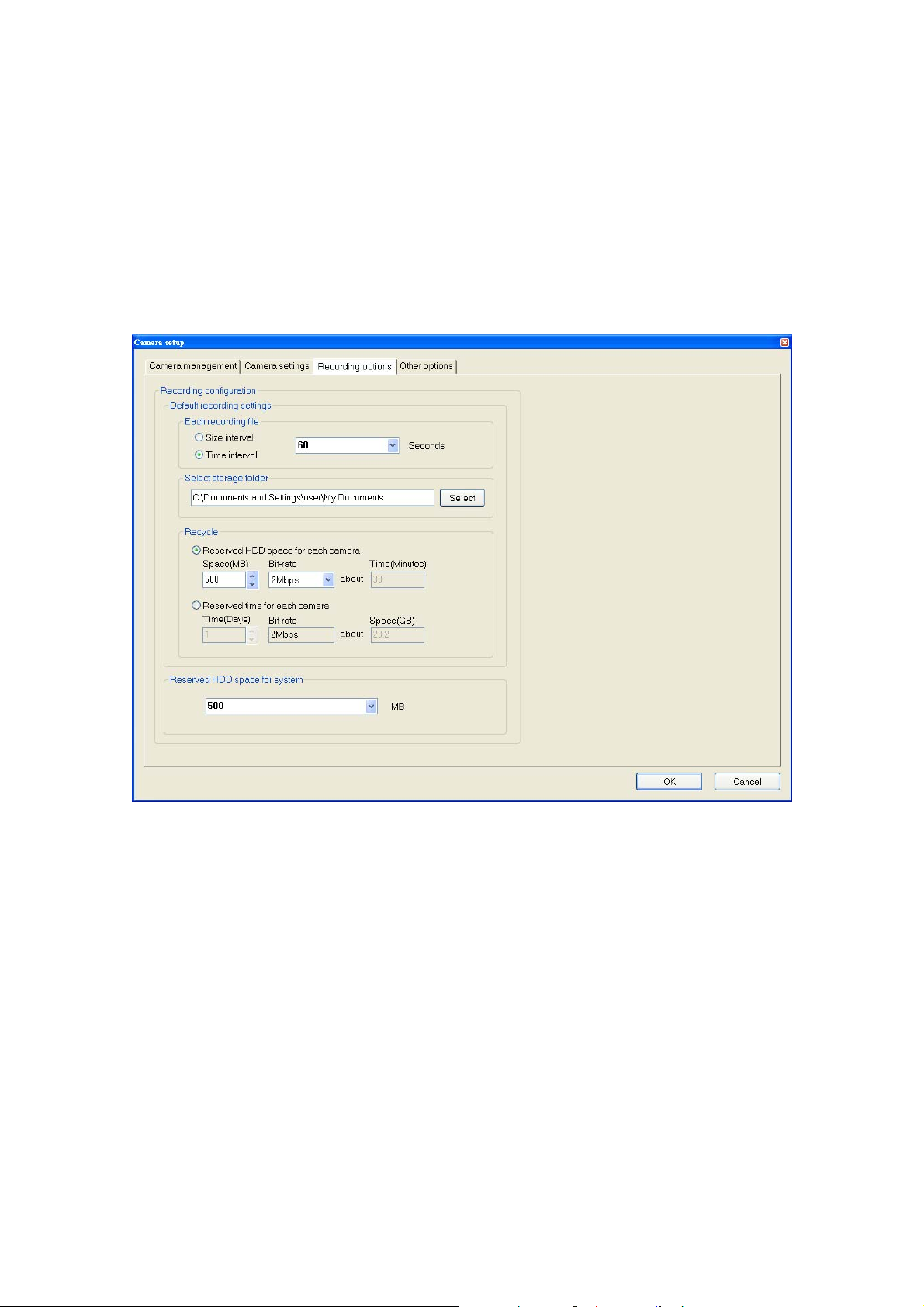
4.3.3 Recording Option
Setup the recording parameters.
Default recording settings
- Size interval: Set the maximum file size for each recording file.
- Time interval: Set the time gap to recording between each recording file.
- Select storage folder: User can change the default storage path. Click Select to browse the new
storage path.
Recycle:
- Reserved HDD space for each camera: Set a storage space limit for activate recycle.
- Reserved time for each camera: Set the storage time limit for activates recycle.
Reserved HDD space for system: Set the hard disk space for the Windows system.
4.3.4 Other Options
Proxy Server
Mark the Proxy Server to enable the proxy server service. Enter the Address and Port of your proxy server
on the network. Enable Bypass proxy server for local network address to allow the intranet connection
doesn’t need to pass through the proxy server.
Time interval of scan
Set the time gap of the Auto Scan in seconds.
Local alert settings
- Motion detection alert sound: Set the alarm sound when motion has detected.
- Digital Input alert sound: Set the alarm sound when camera receives the unusual sound.
- Video loss alert sound: Set the alarm sound when video of the camera is lost.
E-Mail sender settings: click Test to test the correction of the e-mail setting.
- Sender E-mail Address: Enter the sender’s e-mail address.
- Subject title: subject of the mail.
- SMTP Mail Server: Enter the SMTP server of your e-mail account.
- Recipient E-mail Address: Enter the e-mail address that user wants to send the snapshot image.
- Port: Enter the connection port of the mail server.
- User Name: Enter the username or login name for your e-mail account.
- Password: Enter the password for your e-mail account.
56
Page 65

System settings
- Automatically launch this program system starting: The IPCamCenter will execute automatically
when the Windows system is startup.
- Resume Manual Recording state on application startup: When IPCamCenter is startup, the
recording state will be manual.
About: Click it to view the version information of the IPCamCenter.
57
Page 66
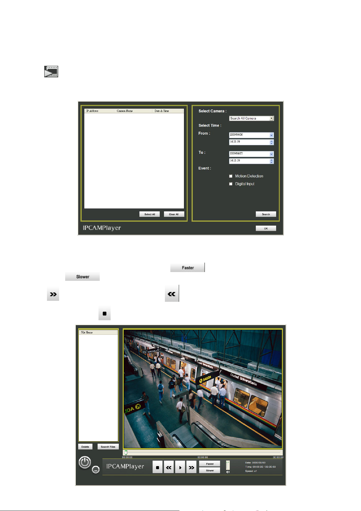
4.4 Playback the Recorded File
If user has enabled the recording on IPCamCenter, then user can playback the recorded file on
To playback the recorded file, follow the below steps:
1. Click
2. The IPCamPlayer will show up and search the recorded file automatically. The search found recorded files
will be listed out.
from IPCamCenter to call out the IPCamPlayer.
IPCamPlayer
.
3. Also, user can search the recorded file by camera, time period, or events. Click
4. Select the recorded file that user wants to view and click OK to start playback.
5. During the playback processing, user can press
to 8x. Press
6. Press
7. To stop playback, press
to go to play next recorded file and to back to last playback recorded file.
button to decrease the playback from 1x to 1/8x.
.
button to increase the playback speed from 1x
Search
to start search.
58
Page 67

Appendix A Technical Specifications
Specifications
Model
Device
Effective Pixels
Min. scene Illumination
F/No
Focu s Lengt h
Depth
Viewing Angle
Motion Detection
Expos ure Control
AGC
White Balance
Compression
Multi-profile
Picture Resolution
Bit Rate
Image Frame Rate
Black/White mode
Digital Zoom
Mirror
Compression
Built-in Microphone
Freque ncy Resp onse
Audio Line Output
Pre-recording/Post- recording
Overwrite
Recording mode
System Log
Ethernet
Protocol
Auto-MDIX
3GPP
WPS
Web Browser
User account
Security
Temperature and humidity
Power Co nsumpt ion
Dimensions (W x H x D)
Weigh t
Indoor/Outdoor
Bundled accessory
SF1301W
Enable/disable; Sensitivity 0~100; Drawing mode - Enable/Disable
1280 x 1024; 1024 x 768; 640 x 480; 512 x 384; 320 x 240; 160 x 120
-15~60℃ (Storage), 90% humidity/0~40℃(Operating), 85% humidity
158g (w/o bracket)
(wireless)
1/4 inch CMOS
1280 x 1024
0.5 Lux
F2.8
f4.5mm
20cm~Infinity
Horizontal:43.6 ˚,Vertical:35.7 ˚, Diagonal:54 ˚
Auto
Yes
Auto
MPEG4/MJPEG dualformat compression simultaneously
Support 4 video streams simultaneously
IE browser - 900K, 1M, 1.25M, 1.5M, 1.75M, 2M
Mobile Video - 64K, 128K, 192K , 256K, 320K, 384K, 448K, 512K
10 fps at 1280x1024; 30 fps at 640x480
Yes
16X
Vertical mirror/Horizontal mirror
AMR/ADPCM
Sensitivity -42dB +/- 3dB (5 Meters distance min.)
S/N Ratio:more than 58 dB; Directivity Omni-directional
50~16000HZ
Output Line-out Forexternal speaker
0~15 seconds/0~15 seconds
Enable/dis able
Continuous/Event/Motion Detection
Up to 500 items stored in flash
Ethernet (10/100 Mbps Fast ) , RJ-45 connector
IPV4, ARP,TCP, UDP, ICMP, DHCP, NTP, DNS, DDNS, SMTP,
FTP, HTTP,Samba, PPPoE, UPnP,RTP,RTCP,RTSP
Yes
Audio codec/AMRVideo codec/MPEG4Protocol/RTSP, RTP
Yes
IE 7.0/FireFox 2.0.7/Safari 3.2.2 or above
Up to 20 users
Password protection:configured by the administrator
6W (DC 5V)
71mm x 44mm x 133mm
Indoor
Bracket
SF1301
136g (w/o bracket)
* Specifications subject to change wi thout prior notice
(wired)
No
59
Page 68

Wireless
Frequency
Channels
Wireless Data Rates
Out Power
Antenna
2.412-2.4835 GHz
11 channels for United States
13 channels for European Countries
13 channels for Japan
IEEE 802.11g: 54, 48, 36, 24, 18, 12, 9, 6 Mbps
IEEE 802.11b: 11, 5.5,2, 1 Mbps
Auto-select or Manual specified.
16 dBM@11b(Typical)
12 dBM@11g(Typical)
Dipole Antenna
- Gain: 2 dBi
- Connector: RP-SMA (M)
- Operating Frequency: 2.4~2.5Ghz
60
 Loading...