

Page 1

SecureCenter
Central Management System
User’s Manual
V1.1.1.1
Page 2

COPYRIGHT
© 2014 AVer Information Inc. All rights reserved.
All rights of this object belong to AVer Information Inc. Reproduced or transmitted in any form or by any
means without the prior written permission of AVer Information Inc. is prohibited. All information or
specifications are subject to change without prior notice.
TRADEMARKS
“AVer” is a t radem a rk owned by AVer Inf orm ati on Inc . Other trade mar ks u sed here in for
description purpose only belong to each of their companies.
DISCLAIMER
No warranty or representation, either expressed or implied, is made with respect to the contents of this
documentation, its quality, performance, merchantability, or fitness for a particular purpose. Information
presented in this documentation has been carefully checked for reliability; however, no responsibility is
assumed for inaccuracies. The information contained in this documentation is subject to change
without notice.
In no event will AVer Information Inc. be liable for direct, indirect, special, incidental, or
consequential damages arising out of the use or inability to use this product or
documentation, even if advised of the possibility of such damages.
Page 3

The caution symbol is intended to alert the user of the importance of the particular
installation and operating instructions. Failure to comply may damage the system.
i
The information symbol is intended to provide additional information for the purpose of
clarification.
Manual Conventions
The following conventions are used throughout this manual.
Page 4

TABLE OF CONTENTS
CHAPTER 1 INTRODUCTION ............................................................................ 1
1.1 Dual Monitors setting ............................................................................................... 2
1.1.1 Graphic card with ATi chipset ........................................................................... 2
1.1.2 Graphic card with NVIDIA chipset .................................................................... 5
CHAPTER 2 SOFTWARE INSTALLATION ........................................................ 6
2.1 Minimum System Requirements .............................................................................. 6
2.2 Installing the SecureCenter Software in Windows 7/8 .............................................. 7
CHAPTER 3 USING THE SECURECENTER ..................................................... 8
3.1 Running theSecureCenter Software ......................................................................... 8
3.1.1 Using the Virtual Keyboard .............................................................................. 8
3.2 Using the SecureCenter Application ......................................................................... 9
3.3 Using the Monitor ................................................................................................ ... 12
3.3.1 Using the Monitor Controller .......................................................................... 13
3.3.2 Familiarizing the Buttons in PTZ Camera Control Panel ................................ 15
3.3.3 Live Playback the Recorded Video ................................................................ 16
3.4 Using the MiniCenter Viewer .................................................................................. 18
3.4.1 Remote Backup ............................................................................................. 20
3.5 To Search the Alarm Event ..................................................................................... 24
3.5.1 Editing the Alarm ............................................................................................ 26
CHAPTER 4 CUSTOMIZING THE SECURECENTER SYSTEM ...................... 28
4.1 System Setting ....................................................................................................... 28
4.2 NVR Setting ........................................................................................................... 34
4.3 Channel Setting ...................................................................................................... 35
4.4 Schedule Setting .................................................................................................... 39
4.4.1 To set schedule at a specific portion of time in that hour: .............................. 40
4.5 Backup Setting ....................................................................................................... 41
4.6 E-MAP Setup ......................................................................................................... 43
Page 5

4.6.1 To Set Up the E-Map ..................................................................................... 43
4.6.2 Add a New Map ............................................................................................. 45
4.6.3 Add a NVR Server ......................................................................................... 46
4.6.4 To Use the E-Map .......................................................................................... 47
4.7 Alarm Setting ................................ ................................ .......................................... 49
4.7.1 To setup an alarm condition ........................................................................... 49
4.7.1.1 To Setup the Call Out List ..................................................................... 50
4.7.1.2 To Setup the Send E-Mail Setting ......................................................... 51
4.7.1.3 To Setup the Alarm Sound Setting ........................................................ 52
4.7.1.4 Launch program ................................ .................................................... 52
4.7.1.5 To Set the MMS/SMS Setting ............................................................... 53
4.7.1.6 Popup Video ......................................................................................... 54
4.8 User Setting ........................................................................................................... 56
CHAPTER 5 USING THE PLAYBACK FUNCTION .......................................... 57
5.1 To Playback the video ............................................................................................ 57
5.2 Using the Local Playback Application ..................................................................... 60
5.3 Using the Download and Playback Application ...................................................... 63
5.4 Using the RealTime Playback Application .............................................................. 65
5.5 To Cut and Save the Wanted Portion of the Recorded Video ................................. 67
5.6 To Bookmark a Section of the Video ...................................................................... 70
5.7 To Search Using the Visual Search ........................................................................ 67
5.8 To Search Using the Event Search ........................................................................ 68
5.9 To Search Using the Intelligent Search .................................................................. 68
Page 6
Chapter 1 Introduction
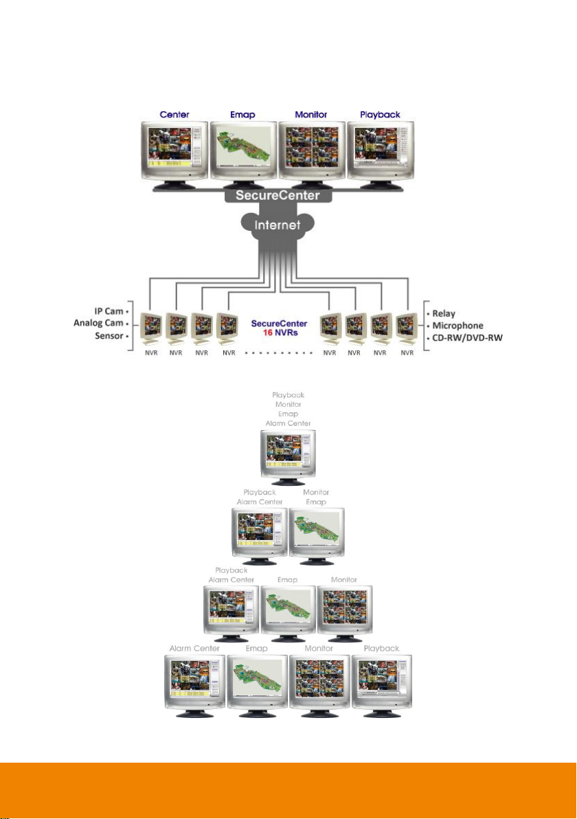
The AVer SecureCenter is a central monitoring system that enables user to monitor up to 16 NVR
servers through an internet connection. Like the NVR program, the SecureCenter system also
automatically records and displays video when an event has occurred on the remote side of the NVR
server. You can also playback video files locally or download from a remote NVR server.
The SecureCenter system supports Single, Dual, Triple and Four monitor displays. User can operate
the SecureCenter system application on different monitors.
1
Page 7
1.1 Dual Monitors setting
Video configuration is different for each different VGA chipsets. Please follow the steps below to setup
the dual monitors display.
The SecureCenter application supports resolution in 1280 x 800、1024 x 768、1280 x 1024、1440 x
900、1680 x 1050、1920 x 1080 and 1920 x 1200.
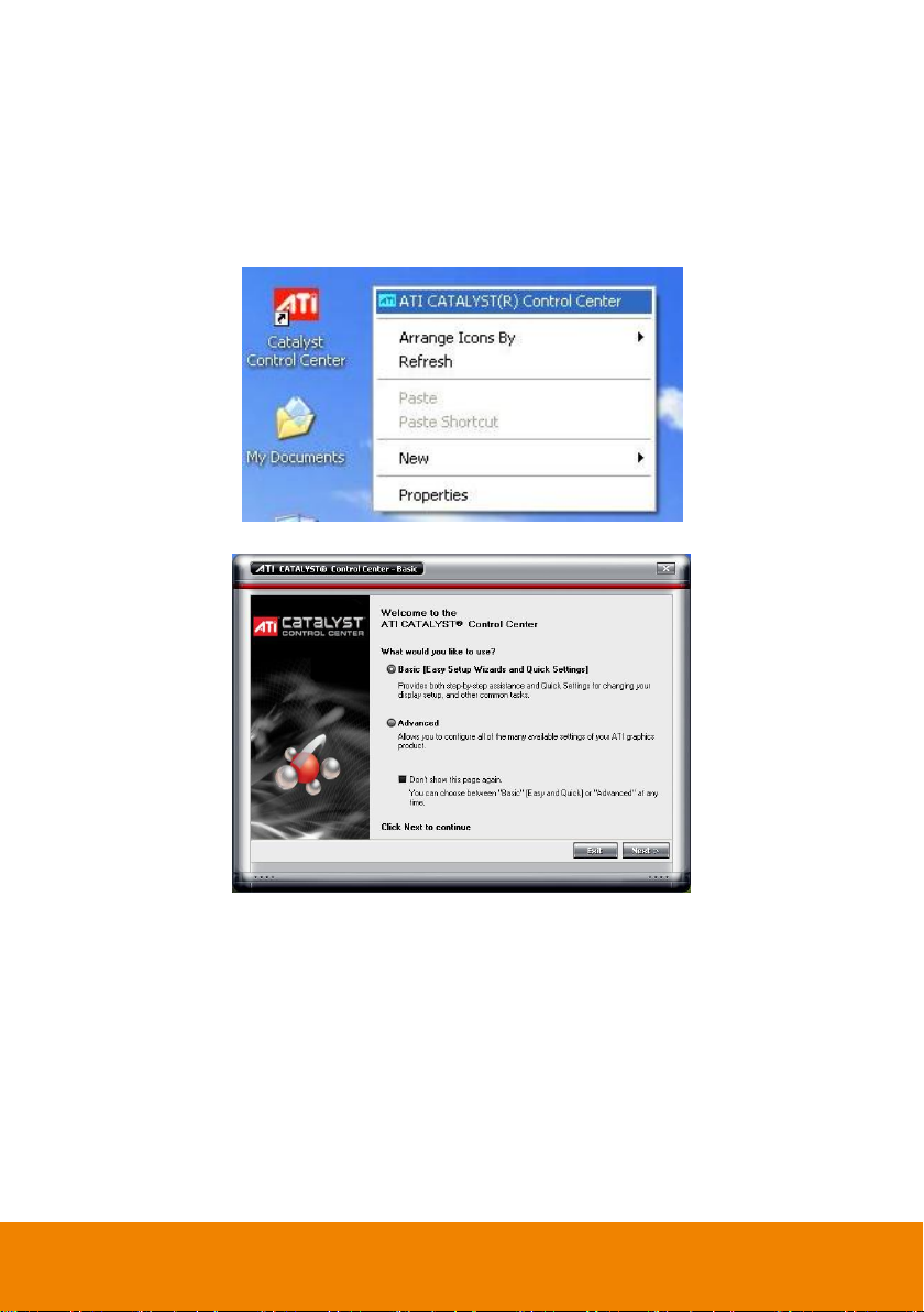
1.1.1 Graphic card with ATi chipset
1. Enter the ATI Catalyst Control Center, user can click the short-cut or right click on the screen.
2. There are two modes to select ─ Basic and Advanced.
2
Page 8
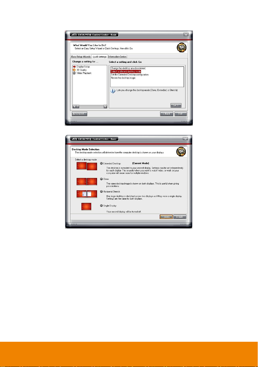
3. If user selected Basic mode, press the Quick Settings tab. Then select the Select a different
desktop mode and click Go.
4. Select the Extended Desktop and then click Finish.
3
Page 9
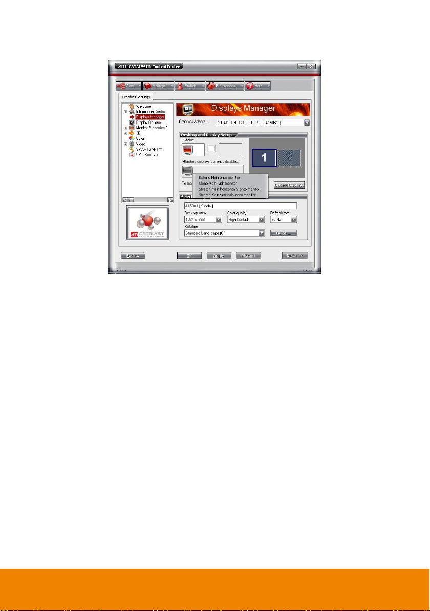
5. If user selected the Advanced mode, click the View button.
6. In Display Manager, right click on the second Display on the right side and select Extend Main
onto monitor.
7. Adjust each monitor resolution to 1280 x 800、1024 x 768、1280 x 1024、1440 x 900、1680 x
1050、1920 x 1080 or 1920 x 1200.
4
Page 10
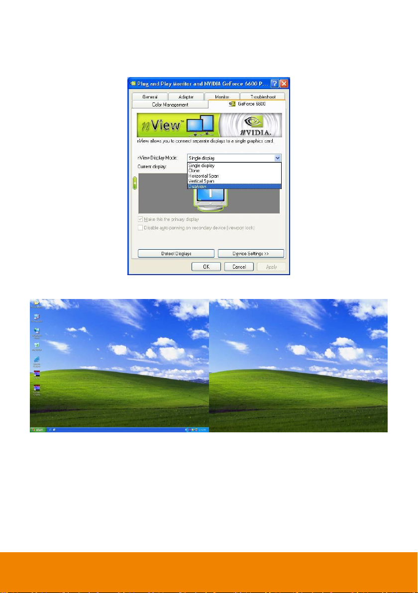
1.1.2 Graphic card with NVIDIA chipset
1. Click the NVIDIA nView, and select the Dualview mode.
2. Adjust each monitor resolution to 1280 x 800、1024 x 768、1280 x 1024、1440 x 900、1680 x
1050、1920 x 1080 or 1920 x 1200.
3. To review if the display mode is correct, you can check the task bar. The task bar will show on the
first monitor only.
Monitor 1 Monitor 2
5
Page 11
- Before installing the software, make sure the Windows OS patches are up to date and
the video graphic card driver is up to date.
- Please disable the User Account Control (UAC) function before install the CMPC
program. To disable UAC, please go to Control Panel >> User Account Control.
After disable UAC function, please restart system, and then, install CMPC
program.
CPU
Pentium 4 3.0GHz or above recommended
OS
Windows XP Professional 32 bit/ 7 32bit & 64bit
RAM
512MB for dual display,1GB for Quad display
Hard disk
120GB or higher
Media
CD-ROM drive
VGA
32-bit high color SVGA graphics card with 256MB video memory and
DirectDraw / YUV Rendering Capability
Audio
Sound card and speakers
Internet capacity
10/100 Base-T Ethernet card or Gigabit Ethernet
Chapter 2 Software Installation
This chapter describes how to install the SecureCenter software.
2.1 Minimum System Requirements
First, must verify if the computer meets the minimum system requirements.
6
Page 12
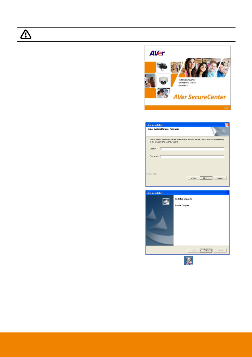
DO NOT install SecureCenter application and ExpressGO application on the one computer
system.
1. Place the installation CD into the CD-ROM drive
then click Install SecureCenter. And follow the
on-screen instructions.
2. Please carefully read the license agreement. Click Yes to accept the agreement.
3. Enter the administrator ID and password.
4. Click Finish.
5. User may now run the SecureCenter program. To run the application, click on your PC
desktop or click Start> > SecureCenter > SecureCenter > SecureCenter.
2.2 Installing the SecureCenter Software in Windows 7/8
7
Page 13
Chapter 3 Using the SecureCenter
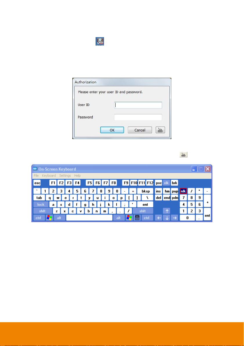
3.1 Running theSecureCenter Software
To run the application, double-click on your PC desktop or click Start > SecureCenter >
SecureCenter > SecureCenter.
For security purposes, some of the features would require you to enter a User ID and Password before
they can be accessed. When the Authorization dialog box appears, key in your User ID and Password.
(If this is the first time, enter the one you have registered when installing the software.)
3.1.1 Using the Virtual Keyboard
If the keyboard is not available, you may use the Virtual Keyboard. Just click to show the virtual
keyboard. For uppercase and lowercase, click shift button.
8
Page 14
Name
Function
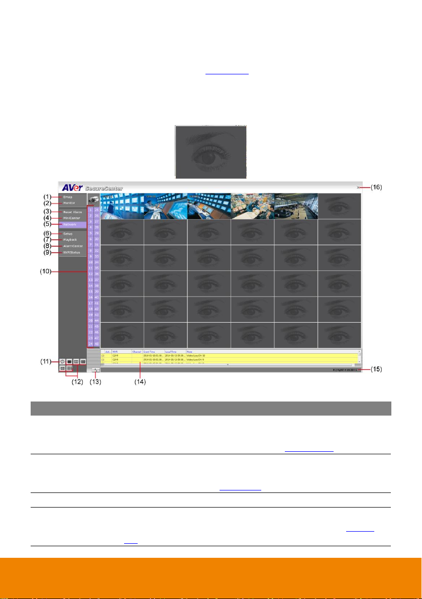
(1) E-map (F3)
Switch to display the map and show the location of the NVR server on
the map. If you are using a single monitor, press ESC to revert back to
the SecureCenter main application( see also Chapter 4.6.2)
(2) Monitor (F4)
Switch to display live video from the selected NVR servers group. If user
is using a single monitor, press ESC to revert back to the SecureCenter
main application (see also Chapter 3.3).
(3) Reset Alarm
Click to reset all NVR alarm status
(4) MiniCenter Viewer
To call out the MiniCenter viewer. Also, user can double click on screen
or alarm event to call out the MiniCenter Viewer.(Also refer to Chapter
3.4 )
3.2 Using the SecureCenter Application
When an alarm occurred on the NVR server, the video is transmitted to the SecureCenter and display
on the main screen. The transmit video can be an image or live video. User can select the type of
video transmitting in System setting (see also Chapter 4.1). You may download and playback the
complete video directly from the NVR server by clicking on the event log. Make sure the main NVR
server is set to send video to the SecureCenter when an alarm has occurred.
The video stream before the eye indicates the latest occurrence. Also, there is a red frame which
indicates the latest occurrence when the video transmitting is alarm image type.
SecureCenter in Alarm Live Video Mode
9
Page 15
Name
Function
(5) Network
Enable/disable the remote alarm data received. This is activated
automatically when the SecureCenter software starts up.
(6) Setup
Configure the SecureCenter system settings. Only the administrator is
authorized to access this command. (see also Chapter 4)
(7) Playback
Select to playback video from the local hard disk or remote NVR server
(see also Chapter 5).
(8) Alarm Center
To view, search, and navigate the alarm (see also Chapter 3.5).
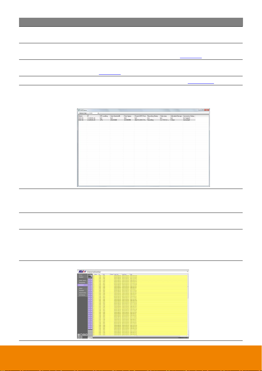
(9) NVR Status
To view all monitor NVRs’ status – Name, IP, CPU usage, Bandwidth
usage, HDD free space, Present NVR Time, Recording Status, Estimated
Storage, Connection status, Video Loss status….and so on.
(10) Camera ID
Show the number of cameras that are being viewed. When you are in
single screen mode, click the camera ID number to switch and view the
camera. This function only available in Alarm Live Video mode.
(11) Refresh
To refresh the alarm video that display on the screen. This function only
available in Alarm Live Video mode.
(12) Split Screen
Mode
Select from 5 different split screen types to view all the cameras. It also
allows you to switch and view different camera number by click Camera
ID in a single screen mode. This function only available in Alarm Live
Video mode.
(13) Log extender /
reduce
Expand and reduce the log viewer
Expanded Log viewer
10
Page 16
Name
Function
(14) Log viewer
List the entire info in event mode or text mode from all NVR servers.
(15) Status
Display the current date, and time
(16) Exit
Call up the Logout dialog box.
In the logout dialog box, you may do the following:
- Exit: To shut down the SecureCenter program. Only the administrator
is authorized to access this command.
- Login: To sign-in as a different user.
- Minimize: To reduce the SecureCenter to taskbar button. The authorization
is required, please enter the pas;sword.
- Cancel: To close the Logout dialog box.
- About: It shows the current SecureCenter software version.
i
There are a few Hot keys for quick switching between the different applications or display
mode on a single monitor system.
- F3: Switches to E-Map mode
- F4: Switches to Monitor mode
- Esc: Switches back to the SecureCenter application main screen
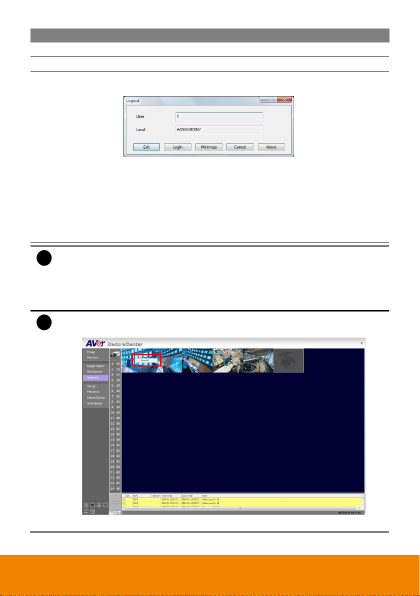
i
When SecureCenter in Alarm Image mode, right-click on the alarm image will call out
Clear All short-cut. Select to clear all current displayed alarm images.
SecureCenter in Alarm Image mode
11
Page 17
i
Right-click on the channel screen could select to start recording.
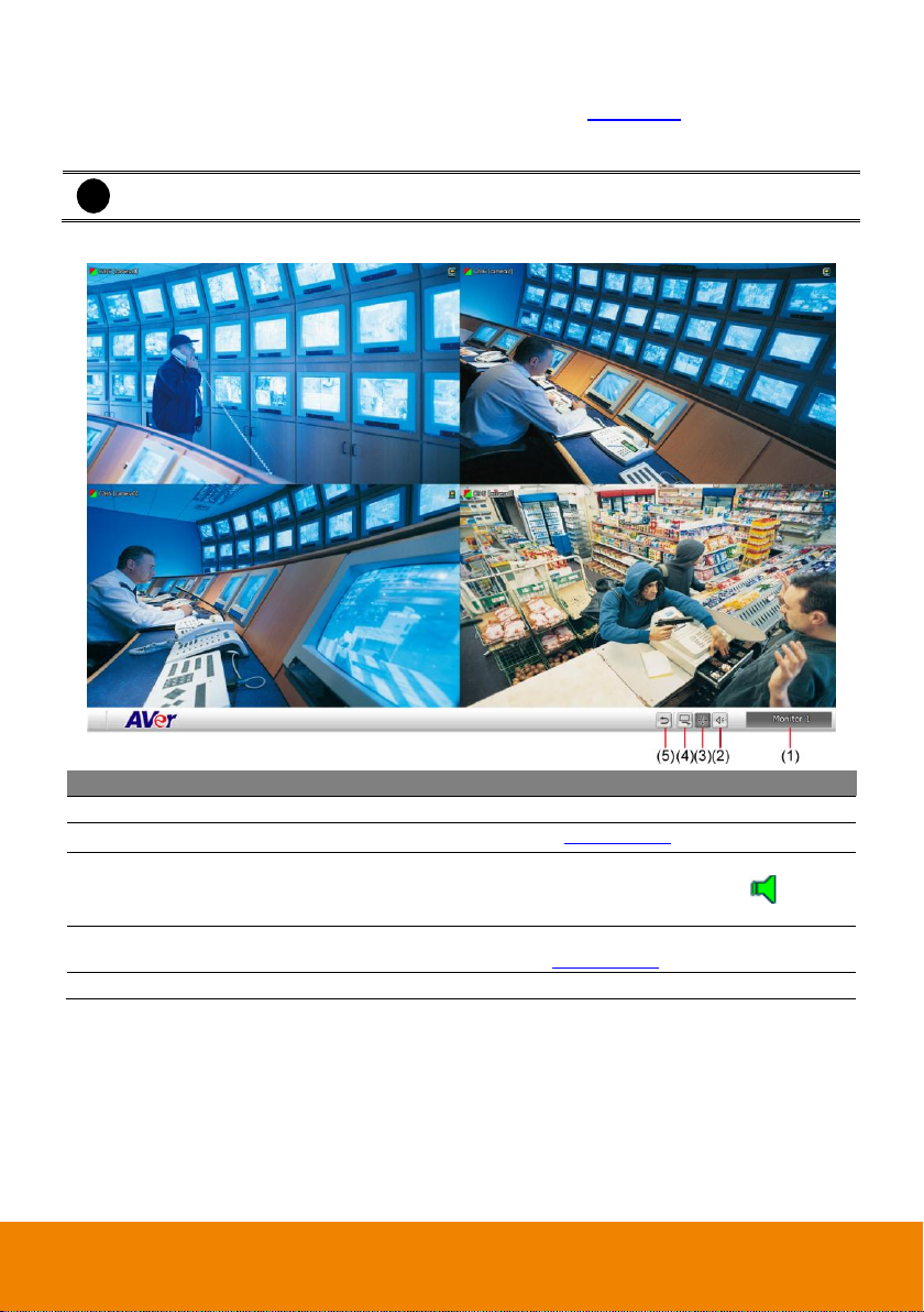
Name
Function
(1) Monitor Name
Display name of current monitor set.
(2) PTZ
To call out PTZ control panel(see also Chapter 3.3.2)
(3) Audio
Enable/disable audio. When audio is enabled, user will see the audio icon
on screen, click on the audio icon (audio icon will turn to green ) of
channel to hear the sound. Each time only can play one channel’s audio.
(4) Monitor
Controller
To call out monitor controller dialog box. User can manage the monitor set
in monitor controller dialog( see also Chapter 3.3.1)
(5) Center
Back to SecureCenter main UI (center UI).
3.3 Using the Monitor
When user has setup the monitor set in Channel Setting (see also Chapter 4.3), then click Monitor to
view all selected cameras live video and playback. The monitor will switch to monitor mode, if user
using more than one monitor, then all enabled monitors will switch to monitor mode.
The following will describe the buttons function on Monitor interface.
12
Page 18

i
User needs to create monitor set in order to using Monitor Controller. To create monitor set,
please go to Setup > Channel Setting (see also Chapter 4.3)
i
- The monitor set is gray that indicates the monitor set is selected and been monitored.
- The monitor 1 ~ 4 are purple that indicate the monitor is monitoring.
- Right-click on monitor and select the Recover to reset the monitor.
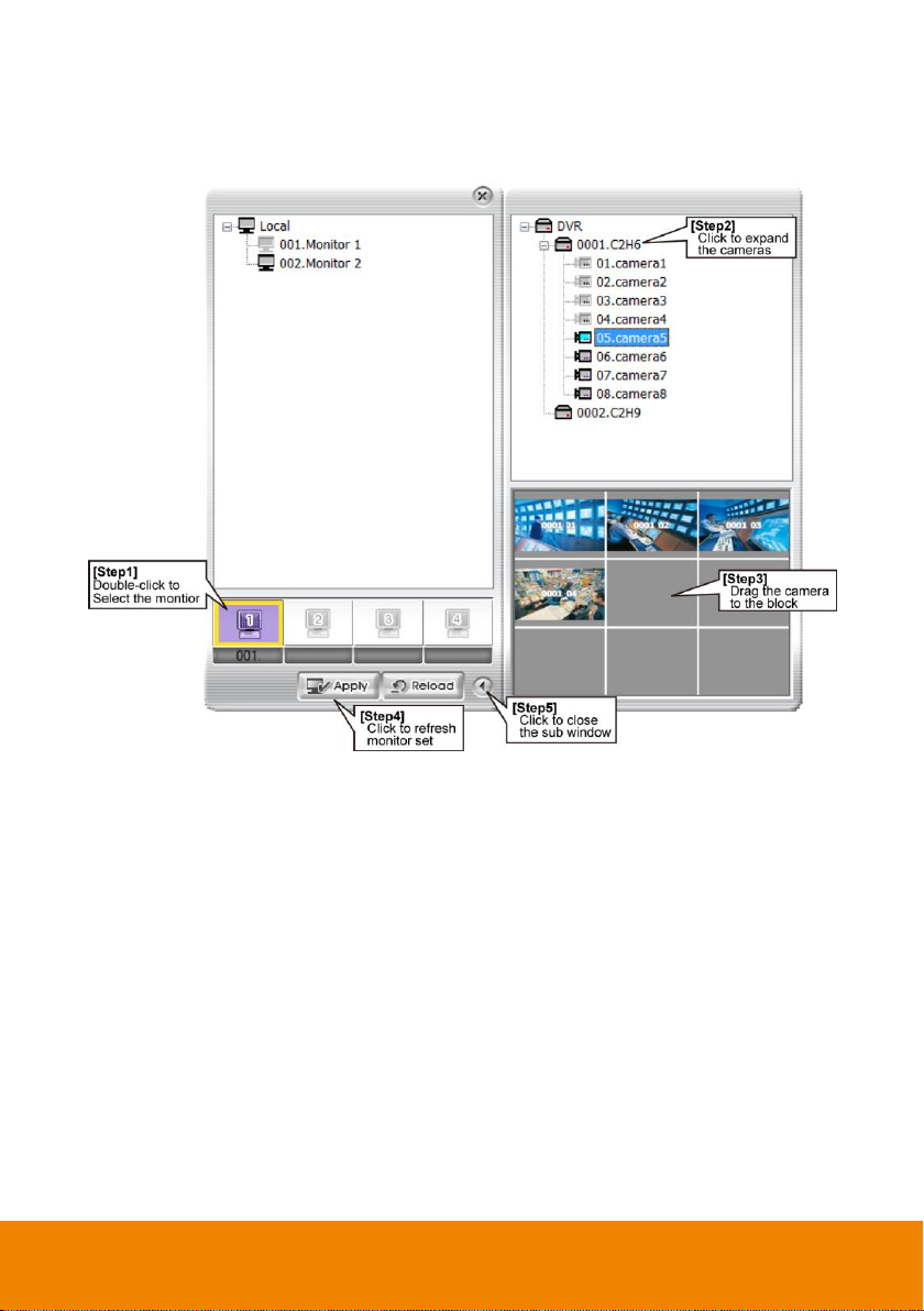
3.3.1 Using the Monitor Controller
User can use Monitor Controller to switch different monitor set for monitoring and add/delete the
channel in monitor set.
1. Click Monitor from SecureCenter main UI.
2. The Monitor Controller window will show up as below shown:
3. Drag the monitor set from monitor list to the monitor (1 ~ 4) and click Apply to activate it. To reset
the monitoring group, click Reload.
4. To configure monitor set, click arrow button to expand the sub Monitor Controller window.
5. Select the monitor. The NVR servers are included in the monitor set will list on sub Monitor
Controller window. The lower part of window display all monitored channels in the monitor set.
6. To add new channels, click the NVR server to un-fold the available cameras. Drag the camera to
the blank channel block that has no channel number and name display
13
Page 19
7. To change the monitored channels’ position, please delete the monitored channels and drag the
channels to the new position. To delete channels from monitor set, right-click on channel and
select Recover.
8. Click Apply to refresh the monitor set.
9. Click arrow button to close the sub window.
14
Page 20
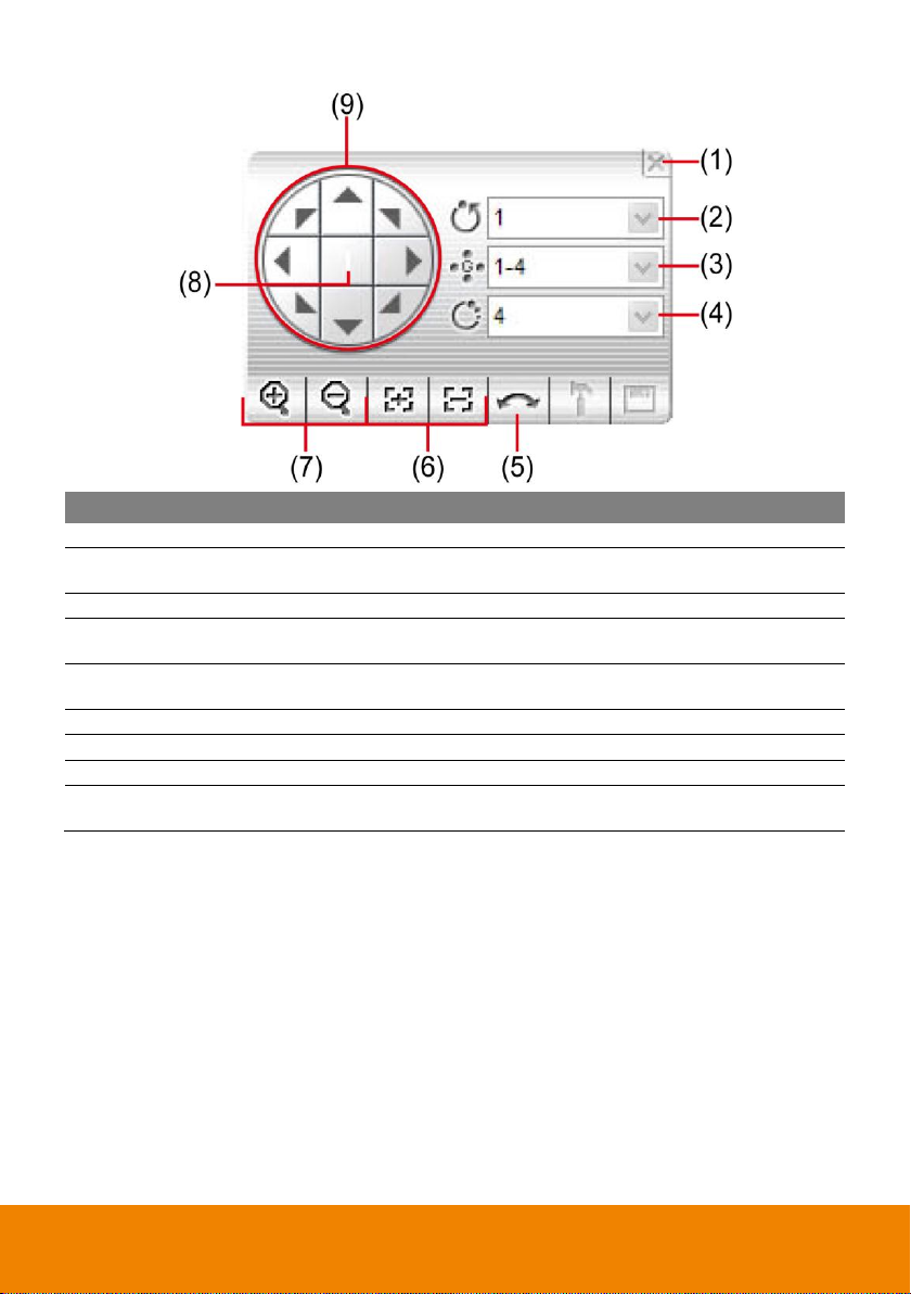
Name
Function
(1) Close
Exit PTZ camera controller.
(2) Camera preset
position number
Move the PTZ camera to the preset point.
(3) Group AutoPan
Select to automatically operate PTZ camera in group.
(4) Direction buttons’
moving speed
Adjust the moving speed of the PTZ camera lens. This speed will apply
to the (11) Direction buttons’ moving speed only.
(5) AutoPan
Operate the PTZ cameras automatically based on the selected camera
group preset position number.
(6) Zoom +/-
Zoom in and out the image.
(7) Focus +/-
Adjust the focus manually to produce clear image.
(8) Camera ID
Display the PTZ camera number that is being operated.
(9) Direction buttons
Move and position the focal point of the PTZ camera. The support of
direction button depends on the PTZ camera.
3.3.2 Familiarizing the Buttons in PTZ Camera Control Panel
15
Page 21

i
Playback function must be enabled. Please go to Setup > Camera and select the monitor
set and enable the playback function ( see also Chapter 4.3)
i
- The icon indicates the channel is in live playback mode.
- Move the mouse course to the bottom of screen, live playback control bar will show
up.
i
- Click channel to switch to full screen mode for operating live playback control button
easily.
- Only supports 4 channel live playback at the same time.
3.3.3 Live Playback the Recorded Video
User can playback recorded video immediately while monitoring from the local SecureCenter server if
the recording is enabled.
1. In Monitor mode, click the preview icon of channel and the channel will start live playback.
2. User can use the live playback control button to operate the playback.
16
Page 22
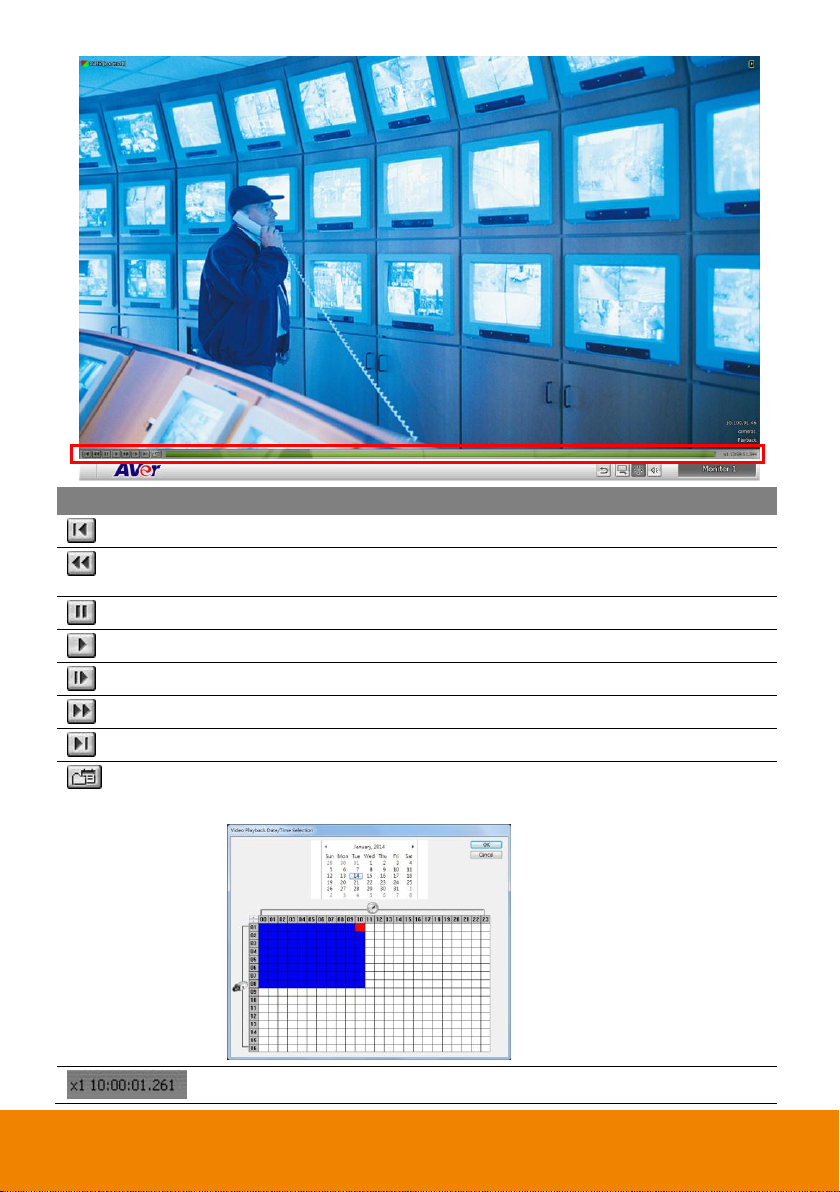
Button
Function
Begin: Move at the beginning of video.
Slower: Play the recorded video file at the speed of 1/2X, 1/4X, 1/8X, or
1/16X.
Pause: Briefly stop playing
Play: Play the video
Next: Go to the next frame.
Faster: Play the recorded video file at the speed of 2x, 4x, 8x, or 16x.
End: Go to the end of the video.
Select recorded vide to playback from remote NVR server hard disk. Select
the date on the calendar and the time from 00 to 23 to where to start playing
the recorded video file.
Display playback speed and recoding time.
17
Page 23
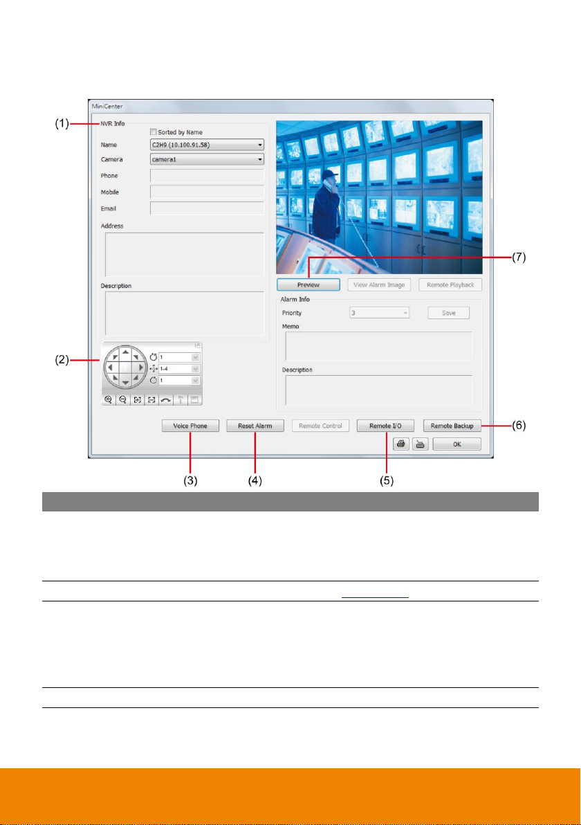
Name
Function
(1) NVR Info
Display the NVR information that user has select to preview. User can
switch to view different NVR or camera by drag down the Name or
camera list. Phone, Address, Mobile, Email, and Description information
were defined when set up the NVR server.
(2) PTZ Control
Control the PTZ camera (see also Chapter 3.3.2).
(3) Voice Phone
Enable/disable 2-way audio function. This function allows the
SecureCenter and NVR server to talk via the internet using a
microphone. Make sure your microphone and speakers work before
using this function. If the NVR server Talk to web-client setting is
disabled, you will not be able to hear from the other side
(4 ) Reset Alarm
Clear the NVR server alarm list.
3.4 Using the MiniCenter Viewer
In Minicenter, user could configure, backup, operate the remote NVR, reset alarm and change priority
of alarm, and setup the camera of remote NVR.
18
Page 24
Name
Function
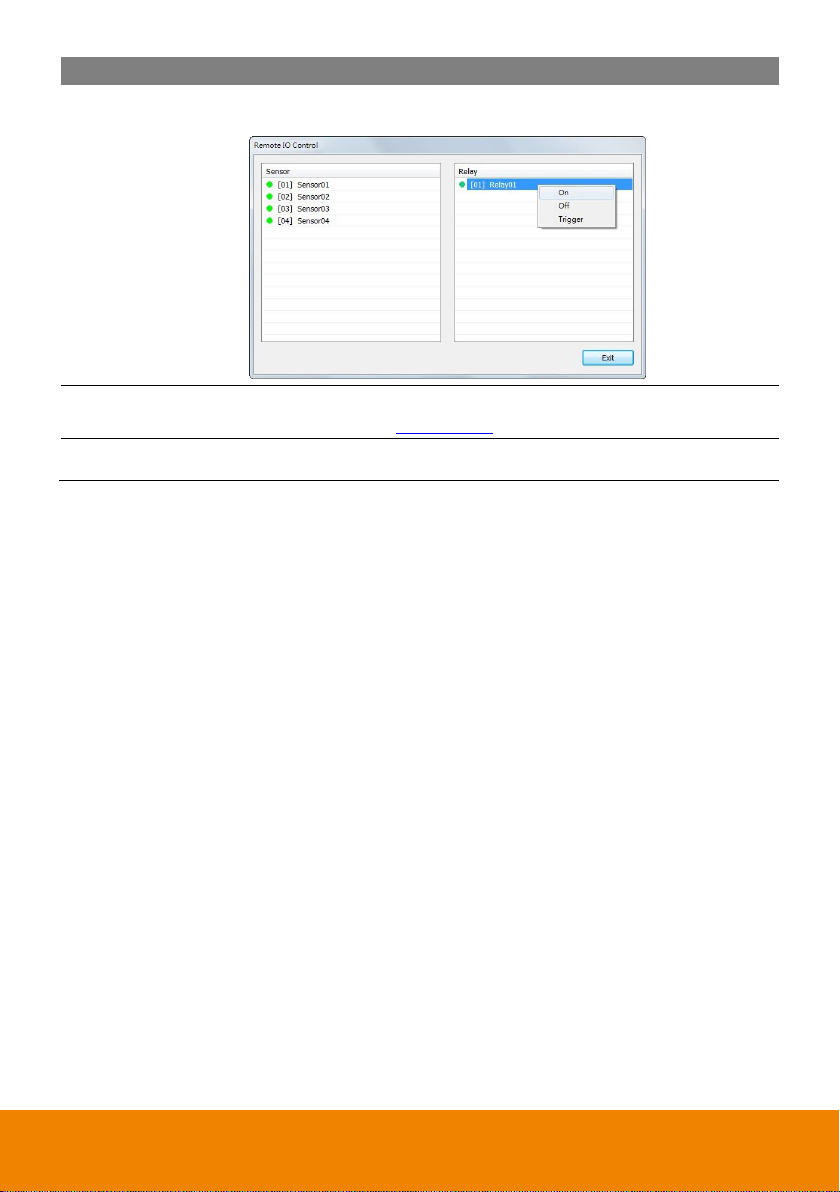
(5) Remote I/O
To view sensor and relay, also to turn on/off relay on remote NVR. Select
the relay and right click to turn on /off or trigger the relay.
(6) Remote Backup
Remote Backup is purely for backing up the *.dvr file from the remote
NVR sever(see also Chapter 3.4.1)
(7) Preview
View live video. User can cancel the connection by clicking Disconnect
button if the connecting time is too long.
19
Page 25
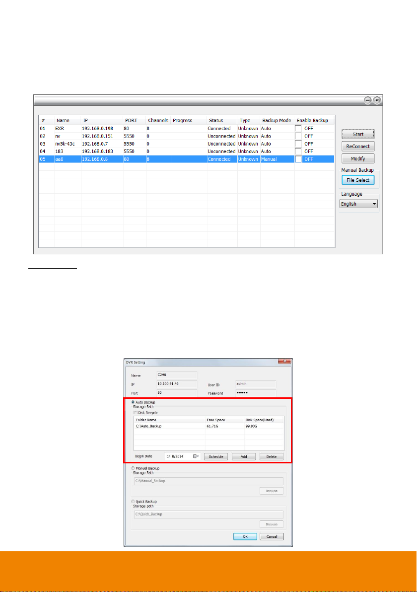
3.4.1 Remote Backup
Remote Backup is purely for backing up the *.dvr file from the NVR sever. You can select between
Auto Backup and Manual Backup. Auto Backup continuously archives one hour of the recorded data at
a time, starting from the specified date. As for Manual Backup, it only archives the recorded data of
selected date.
Auto Backup:
1. Click Remote backup button from Minicenter UI.
2. The Remote backup window will show up and list all added NVR servers.
3. Make sure SecureCenter is connecting to NVR servers. If lost the connection with NVR server,
select the NVR server and click Reconnect button.
4. Select the NVR server that user wants to backup by marking the Enable Backup check box. The
marked Enable Backup will change to ON status.
5. And then, the SecureCenter will start to backup.
20
Page 26

Manual Backup:
1. Click Remote backup button from Minicenter UI.
2. Select the NVR server and click Modify button.
3. Select the Manual Backup at NVR setting dialog. And, user can change the backup direction by
clicking Browse button.
4. And the, click OK to save the setting.
5. The Backup Mode of NVR server will change to Manual.
21
Page 27
6. To execute manual backup, select the file first. Click File Select and select the files that user
wants to backup and click OK.
7. Then, click Start to backup.
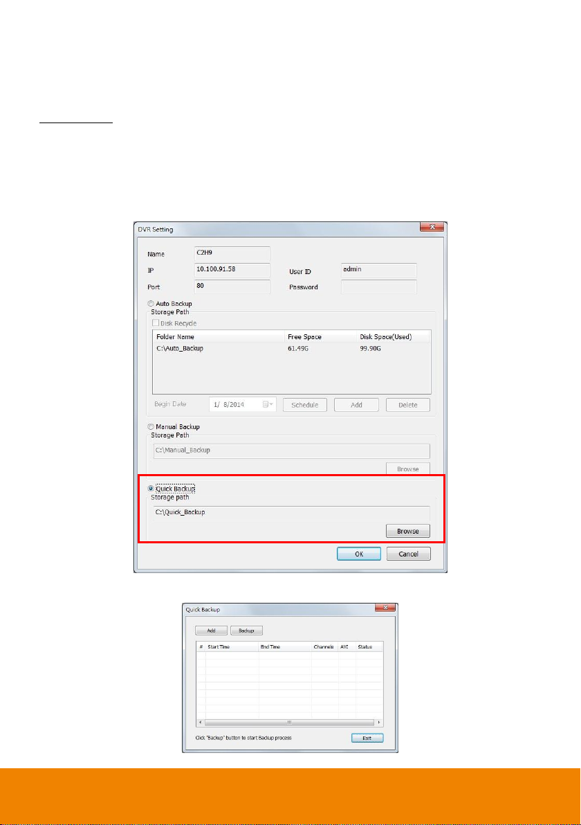
Quick Backup: To backup the selected date, time period and channel immediately.
1. Click Remote backup button from Minicenter UI.
2. Select the NVR server and click Modify button. If the Stop button is displayed, click it change to
Start button.
3. In NVR Setting, select Quick Backup option.
4. Click Browse to set the storage path.
5. Click OK and the Quick Backup dialog box will appear.
22
Page 28

6. Click Add to select the date, start/end time, and channel that user wants to backup. After selecting,
click OK to confirm. User can add multiple backup time file by repeating this step.
7. In Quick Backup dialog box, user will see the selected time period for backup is listed. Click
Backup button to start backup.
23
Page 29
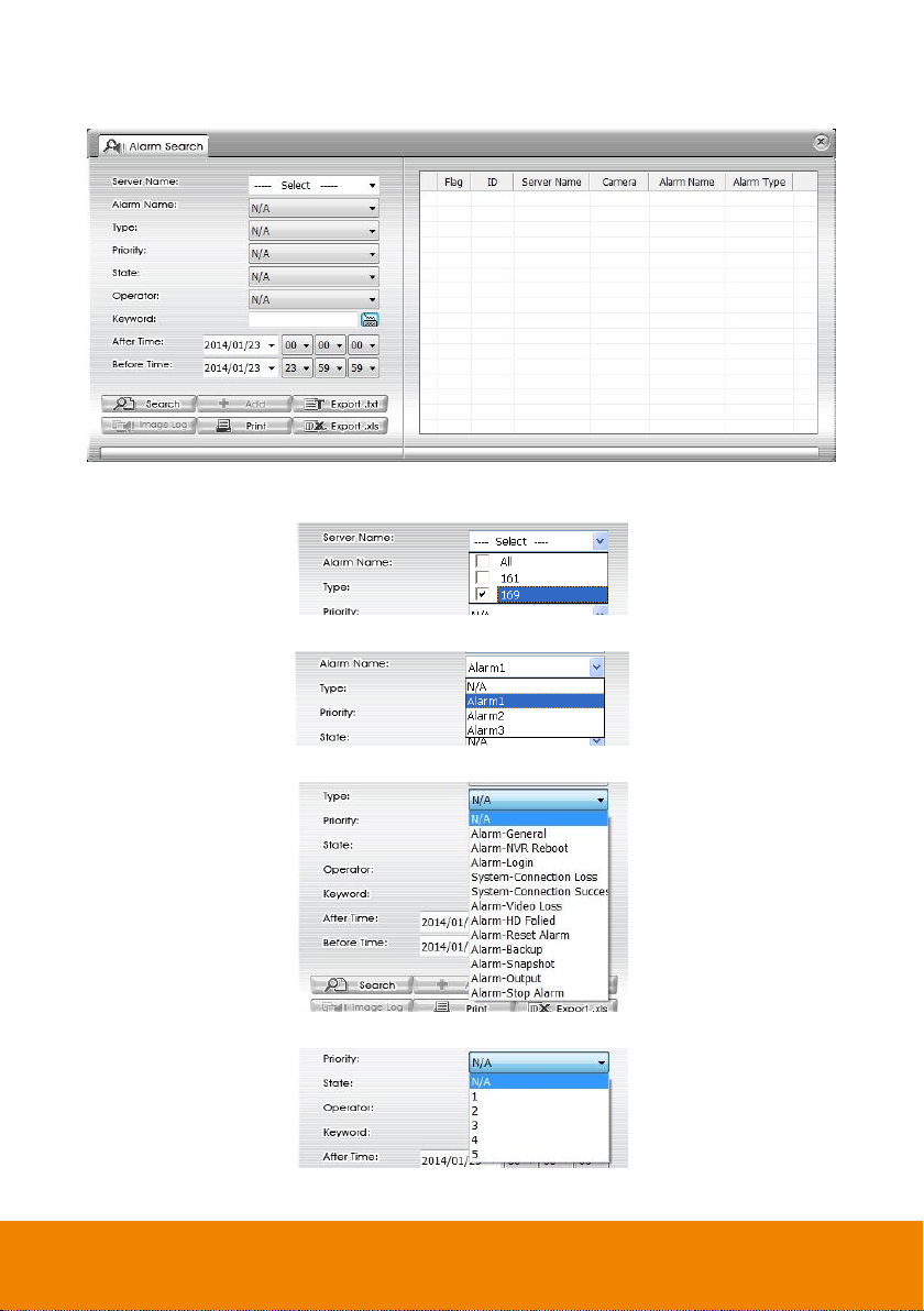
3.5 To Search the Alarm Event
User can search the alarm event by the conditions.
Set the follow conditions to search the wanted alarm events.
Server Name: select the NVR or select All.
Alarm Name: select the alarm that user wants to search for.
Type: select the alarm condition that user wants to search for.
Priority: select the priority level of alarm that user wants to search for.
24
Page 30

State: select the alarm status that wants to search
Operator: select the operator that wants to search
Keyword: enter the specific word string to search.
After/Before Time: set a specific time period to search.
When the search conditions are set, click Search to start searching. If user doesn’t set any conditions,
the system still will start search when click Search button. And the, result will be all alarm events. The
search result will display on the right column of Alarm Search window.
The result of search can be print by clicking Print button. Also, the search result can be save as in *.txt
and *.xls format by clicking Export .txt or Export .xls button.
25
Page 31

3.5.1 Editing the Alarm
User can select the alarm to assign to different operator, change the priority of alarm, and change
status of alarm.
1. In Search result list, double-click on the alarm that user wants to edit it. The Alarm Information
Setting window will show up.
2. Click Edit Information button and user can change the priority, state, and operator of the alarm.
3. Click Save Information to save the changes.
26
Page 32
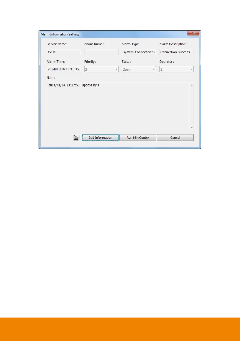
4. Record of changes is displayed in Note column.
5. Click Run MiniCenter button to call out MiniCenter window(also see Chapter 3.4)
27
Page 33
Chapter 4 Customizing the SecureCenter System
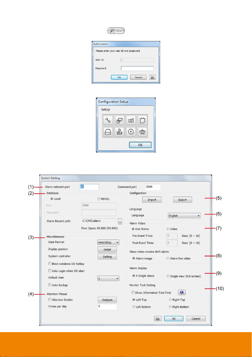
In the SecureCenter application, click the button to customize the SecureCenter system. In
the Authorization dialog box, enter the administrator User ID and Password.
When the SecureCenter configuration setup selection appears, select and click the buttons you want
to change the setting.
4.1 System Setting
In the System Setting dialog box, click OK to accept and start to reload the new setting, and Cancel to
exit without saving.
28
Page 34
i
If SecureCenter system is going to transmit the received alarm to Remote iAlarm center,
please must select the MySQL as the database.
(1) Alarm Network Port
Select a port for receiving alarm video from NVR server. Any network service port can be
assigned as long as the port doesn’t conflict with current network service. The default port is 80.
(2) Database
Local: The default setting.
MySQL: If SecureCenter server is sending the received alarm to the Remite iAlarm agent,
please select MySQL as the database. Please enter the communication Port of MySQL
server and the login Password.
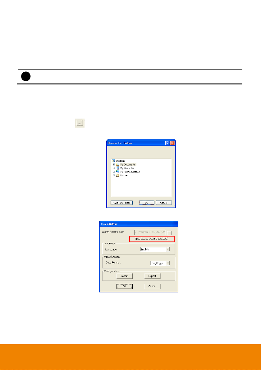
Alarm Record Path
By default, the alarm folder is automatically generated to where the SecureCenter application is
installed and for saving the alarm clip videos and log files. The suggested hard disk capacity for
storing the alarm video is 30GB.
1. Click Setup.
2. In the Authorization dialog box, enter the administrator User ID and Password.
3. Click System > . In the Browse For Folder dialog box, locate where you want to store
the alarm video clip. Click Make New Folder to create new folder, OK to accept and Cancel
to exit.
4. The text below the Alarm Record path text box shows the hard disk free space and total
space in parenthesis.
5. In the System Setting dialog box, click OK to start reloading the new setting and Cancel to
exit without saving the new setting.
29
Page 35
i
The Model of System Controller must match on the System Controller site.
(3) Miscellaneous
Date Format : Select from different date formats
1. Click Setup.
2. In the Authorization dialog box, enter the administrator User ID and Password.
3. Click System.
4. In the Date Format drop down list, click and select the style.
5. In the System Setting dialog box, click OK to accept the new setting and Cancel to exit
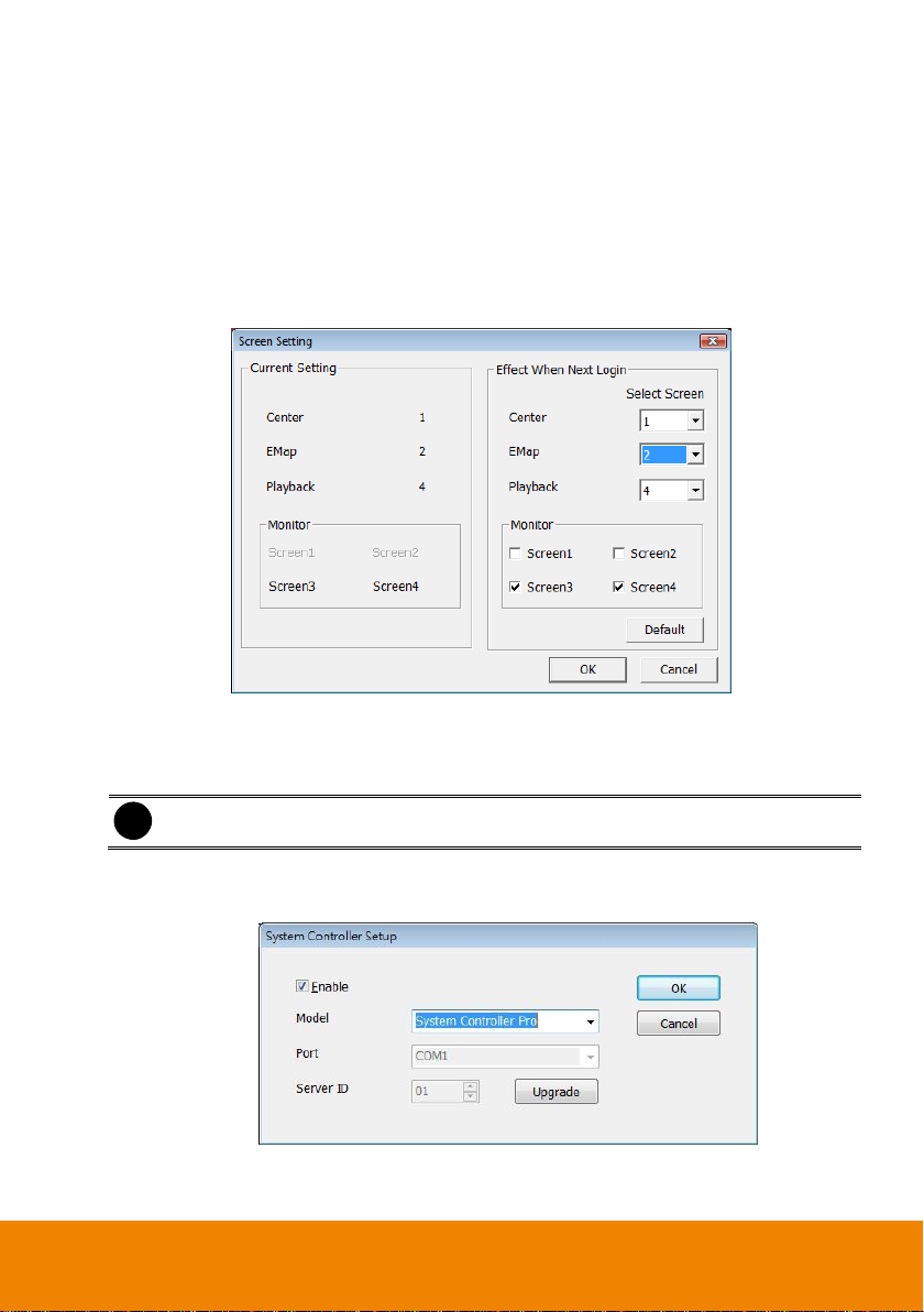
Display position: SecureCenter system supports up to 4 monitors, users are allowed to
System Controller – To configure the parameters that is for communicating with the
without saving the new setting.
customize the display position that to decide the Center, Emap, Monitor, or Playback to be
displayed on which monitor screen. Click Detail to select the display screen setting. The
new screen display setting will be effect at next time login.
System Controller (an optional accessory). Also please refer to user manual of the
System Controller. Click Setting to configure system controller.
USB Connection: SecureCenter can connect with System Controller through the
USB port. Follow the below description to enable the connection between
SecureCenter server and System Controller.
Enable – Mark the check box to enable the System Controller function.
Model – Select System Controller Pro as the Model.
30
Page 36
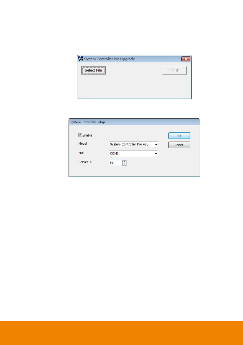
Upgrade – To update the firmware of the System Controller. Click Upgrade button
and click Select File button. And then, select the firmware file and click OK. The
upgrade process will start. The upgrade firmware may have more than one file.
Therefore, click OK and locate the firmware file to upgrade another file. When the
upgrade process is done, click Finish to complete.
RS485 Connection: Connecting SecureCenter with System Controller through RS485
port on the System Controller. Follow the below description to enable the connection
between SecureCenter server and System Controller.
Enable – Mark the check box to enable the System Controller function.
Model – Select System Controller Pro 485 as the Model.
Port – Select the com port that is connected with the System Controller.
Server ID – Set an ID for SecureCenter server (0~99). This ID is a SecureCenter
server ID for System Controller to select.
Block Windows OS hotkey: Deactivate the [Ctrl-Alt-Del] and [Windows] keyboard key
functions.
Auto Login when OS start: Execute the SecureCenter when the operating system is
started.
Default User: Automatically log in to the selected default user when the SecureCenter is
started.
Auto Backup: The backup will automatically execute when the backup setting has set.
31
Page 37

(4) Attention Please
Check the attentiveness of the person who is monitoring the system. You may set the number of
times the Attention dialog box to appear in a day in Times per day text box. To check the graph
on how fast the person response, click Analysis. When this feature is enabled, the Attention
dialog box would appear. The person who is monitoring the system must enter the same number
that appears from the left box at the right text box and then click OK.
(5) Configuration
Import / Export the SecureCenter system configuration.
(6) Language
Customize the system to display the tool tips and dialogs based on the selected language. By
default the set language is in English.
1. Click Setup.
2. In the Authorization dialog box, enter the administrator User ID and Password.
3. Click System.
4. In the Language drop down list, click and select the language.
(7) Alarm Video
Set up the video transition when alarm occurs.
- One frame: a single video frame will be transmitted when alarm occurs.
- Pre/Post Event Time: Set the video duration before and after the event to send
(8) Show when receive NVR alarm
Select the type of received alarm format – Alarm image or Alarm Live Video.
- Alarm image: Only display alarm image and no live video previewing.
- Alarm Live Video: User can view alarm live video.
(9) Alarm Display
Select the alarm display on screen. User can select to display 4-split pop-up alarm display or one
full screen alarm display on screen. This is co-work with video pop-up function in Chapter 4.7.1.6.
32
Page 38

The font and color of information text will be
displayed as user has configured.
User can press F1 to disable/enable camera
information display.
(10) Monitor Text Setting
Enable/disable the camera information display and display position on the monitor screen. To
configure font, click .
33
Page 39
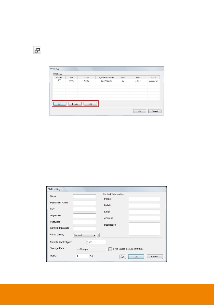
4.2 NVR Setting
Display the list of all NVR servers. User may add up to 16 NVR servers, delete and modify the NVR
setting.
1. Click Setup from SecureCenter main interface.
2. In the Authorization dialog box, enter the administrator User ID and Password.
3. Click (NVR Setting).
4. In the NVR Setup section, click Add to insert, Delete to remove and Edit to modify NVR server
setting.
5. To continue adding a NVR, in the text box, enter the name, IP/Domain, Login User, Password,
Confirm Password of the remote NVR server.
6. If necessary, fill up the contact information to let the personnel in the SecureCenter side know
whom to get in touch with when an event has occurred.
7. Select the Video Quality for video display on the SecureCenter system monitor screen. The
default value is Auto.
8. Enter the remote accessing port of NVR server in Remote Control port column. The default
value is 5555.
9. Set the Storage Path for saving the recorded video data of the selected cameras on the Monitor
screen.
10. Set the max video recorded storage capacity of this NVR server on the SecureCenter system
server. Enter the value in Quota.
11. In the NVR Settings dialog box, click OK to accept the new setting and Cancel to exit without
saving the new setting. The SecureCenter system will connect to NVR server. If the connecting
time takes too long, user can click Disconnect button to cancel the connect action.
34
Page 40
i
The maximum number of Monitor is 128.
i
SecureCenter only supports two monitor set for recording.
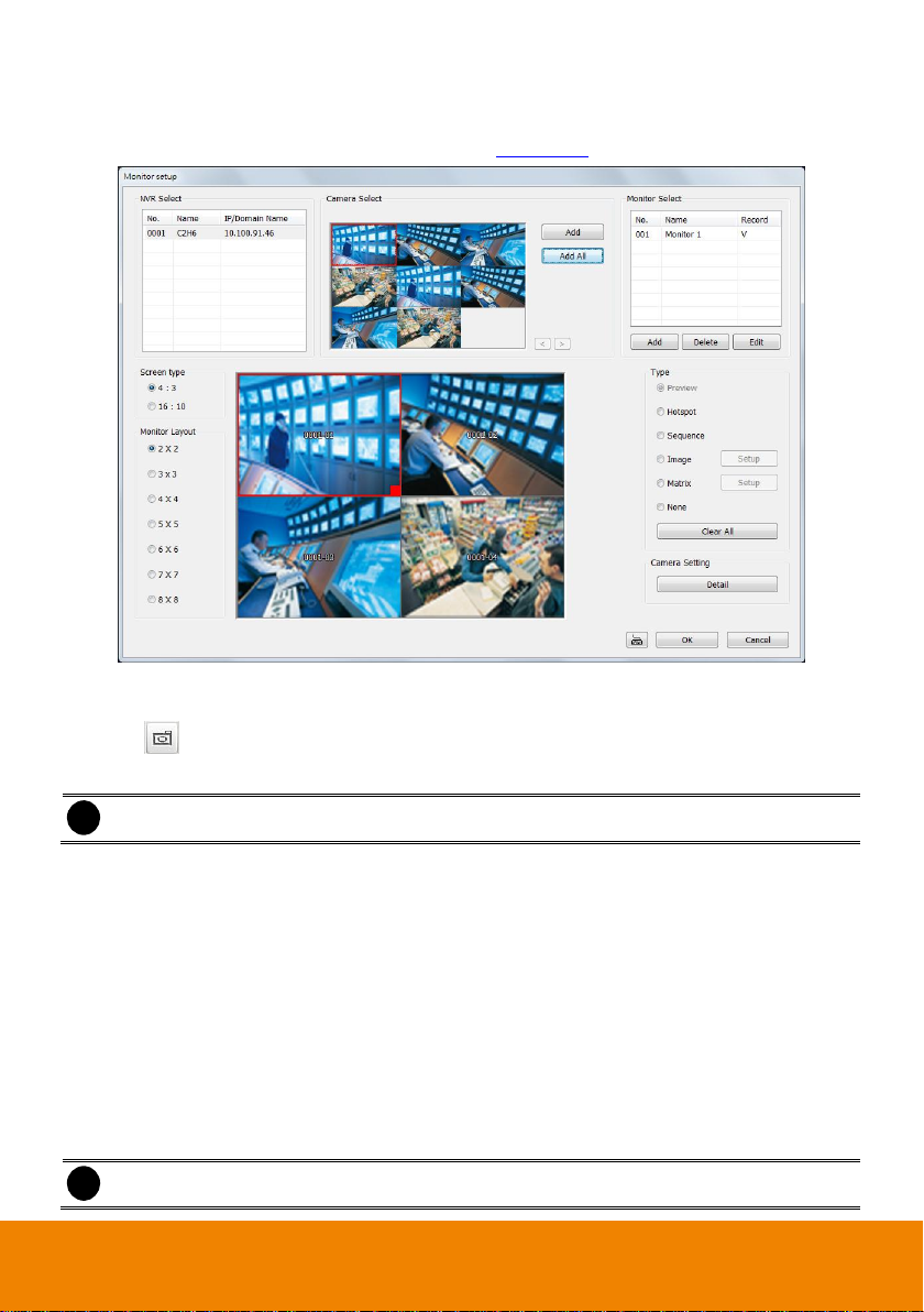
4.3 Channel Setting
Select the camera from different NVR servers in order to monitor on same screen. The selected
cameras will be displayed on Monitor screen (see also Chapter 3.3).
1. Click Setup from SecureCenter main interface.
2. In the Authorization dialog box, enter the administrator User ID and Password.
3. Click (Channel Setting).
4. Click Add to create a monitor set. Enter a name in Name column (12 characters only).
5. Mark Enable Autoscan and click Detail to select the monitor set for sequential display on the
Monitor. When monitor set is an auto scan monitor set, it is no need to select any cameras for
monitoring.
6. Enable Add into Autoscan list will make the monitor set became one of auto scan list.
7. To record the cameras video, mark the Record box. Otherwise, the cameras video will not be
saved on the SecureCenter system hard disk.
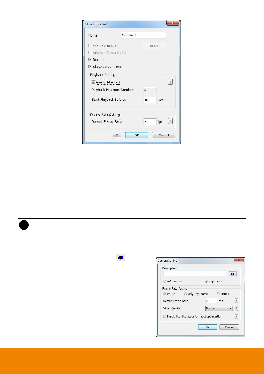
8. Mark Show Server Time to display the time on Monitor screen.
9. If user wants to playback the recorded video of monitor set, mark Enable Playback and enter
the time (sec.) in Start Playback Before that is when start playback will start from the present
time backward the time user has setup. User can set the camera transmitting Frame Rate, but
the real transmitting frame rate depends on camera setting.
10. Click OK to save the setting.
35
Page 41
i
User can drag the camera channel to Monitor Layout window directly.
11. After the Monitor set has created, select the NVR server. Then, the cameras of the NVR server
will display on the Camera Select window. User can combines different cameras from different
NVR servers as a monitor set. And all cameras can be selected by different Monitor set repeat.
12. User can depend on the LCD monitor size to select the screen type – 4:3 (regular screen monitor)
or 16:10 (wide screen monitor). Then, select the Monitor Layout of screen type.
13. Select the camera that user wants to add, and then click Add button. The selected camera will
be added to Monitor Layout window. User can add up to 64 cameras in 4:3 screen type and 80
cameras in 16:10 screen type. To remove the camera from the Monitor Layout window, select
the camera and click Delete button. To delete all cameras, click Clear All button. User can enter
a description for a channel.
14. In monitor set, each camera can be configured the name, transmitting type, and frame rate.
Select the camera in monitor layout window and click Detail button of Camera Setting. And then,
enter the name for the camera and select display position (Left-bottom or Right-bottom) of the
camera name on monitor screen; click to change
the font.
15. Select the transmitting type by click the radio button –
By Fps, Only Key Frame, or Motion. And then, set
the frame rate of the camera in Default Frame Rate
column. The value of frame rate will both apply to live
video and recording.
16. Also, user can select the Video Quality – High,
Medium, Low, or Auto. Mark the Enable live
displayer for most optimization can improve the live
video frame rate of the IP camera (jpeg megapixel)
when viewing the multiple channels.
36
Page 42

The camera description will be
displayed as user has set.
17. In Monitor Layout window, user also can set the channel for specific type functions. In Monitor
Layout window, select one of blank channel and click the radio button of type (Hotspot,
Sequence, Matrix, Image, or None).
Hotspot: To set the channel for displaying selected camera channel video in enlarge view.
After adding the cameras to monitor layout, select the camera that wants to be the hotspot
channel and click Hotspot in Type to set the hotspot channel.
37
Page 43
i
On the NVR site, user need to enable and configure the matrix to send to
SecureCenter (please refer to Alarm Setting of NVR user’s manual).
Sequence: Set the selected channel to automatically switch to display all camera channels
in cycle.
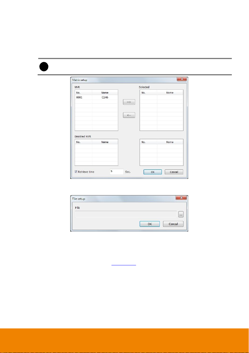
Matrix: set the selected channel to receive and display the alarm event from selected NVR
servers. Click Setup to select the NVR servers. Enable the Retrieve time to set a period
time (0 ~ 255 sec) for alarm event to display. If the retrieve time doesn’t enable, the alarm
event will display on screen until next alarm event come in.
Image: To insert an image on selected channel. The image supports *.bmp and *.jpg format.
Click Setup and browse where the image located is.
18. Click OK to save the setup. To exit without saving, click Cancel.
19. To delete the monitor set, select the monitor set in Monitor Select window and click Delete
button.
20. To modify the monitor set, select the monitor set in Monitor Select window and click Edit button.
21. To use the Monitor function, please see Chapter 3.3.
38
Page 44

i
The Monitor set can be scheduled only when the recoding is enabled.
i
Make sure the backup folder and storage folder are not on the same drive.
4.4 Schedule Setting
Schedule to record or backup of all the cameras either weekly or one time.
1. Select the Monitor set for scheduling.
2. Select the date in the calendar. Use and buttons to shift the calendar to the left or right.
3. Select the condition you want to schedule in the drop down list.
- Record
Activate all the cameras to start video recording at the set time based on the Recording setting
- Backup
Save another copy of all the data at the set time and specified backup path. NVR
automatically updates and only backup the data that are not yet included in the archive. To
assign backup path, click .
4. Specify to either schedule it weekly or one time. Click to make a selection.
5. Click on the blocks to set the schedule (see also Chapter 4.4.1). Or click All to select all. To store
the setting, click Save. To remove the settings, click Clear.
6. To end Schedule Setting, click OK to exit and accept the setting and Cancel to exit without
saving the setting.
39
Page 45

4.4.1 To set schedule at a specific portion of time in that hour:
1. Right click the colored blocks.
2. In the Select time dialog box, click to enable or disable the portion you want to set.
3. Click OK to accept the setting and Cancel to exit without saving the setting.
40
Page 46

Selected Files
: Show the number of files selected.
Require Space
: Show the total size of the selected file.
4.5 Backup Setting
Backup the recorded files from NVR server.
1. Select the NVR that wants to backup.
2. Select the date of the recorded file in the calendar you want to backup. Use and buttons to
shift the calendar to the left or right.
3. In the table below, click on the blue block to select the recorded file or click camera (01~16) or
time (00~23) to select the whole row or column. The blue block turns red when it is selected. The
block that appears in white doesn’t have data. If you want to set the specific time, right-click on the
selected block. Then, set the time to start and end.
4. Check the information beside the calendar.
5. Enable Auto partition and select to divide the file size into DVD-R or CD-R. NVR automatically
backup and divide the file sizes to facilitate burning into DVD or CD disc.
41
Page 47

6. Enable Include player when backup that will included a player program for playback backup file
in backup folder when backup. Only administrator user has the authority to enable or disable this
function.
7. If you do NOT want to keep the recorded file in the storage folder, enable Delete files after
Backup check box.
8. Click to set the path on where to store the backup file.
9. Click to start archiving the selected file.
10. In the Processing… dialog box, to stop archiving press Abort. When done, in the Backup Path list,
shows the archived item. To burn the file in CD, you need to have NERO 6 or above installed in
your PC then select the item in the list and click Burn. Click Exit to end this procedure and burn it
later.
11. In CD/DVD Backup, enable/disable Delete file after burning check box to remove the archived file
after burning. Click Burn to start and Exit to cancel this process.
42
Page 48

4.6 E-MAP Setup
Holds up to 64 maps in *.bmp/*.jpg format. The map is hierarchy in structure and users can add a map
on another map. User also may add the NVR icons on the map.
4.6.1 To Set Up the E-Map
1. Click Setup.
2. In the Authorization dialog box, enter the administrator User ID and Password.
3. Click (E-Map).
4. The E-Map interface will show up in assigned monitor if user is using multiple monitors for the
SecureCenter system. If user is using single monitor for the SecureCenter application, the E-Map
interface will show up in front of the SecureCenter application interface. Press Esc or click
Center button to switch back to SecureCenter application interface or press F3 to switch to EMap interface again.
5. On the E-Map interface:
- (1) Map List: list all E-Map and all NVR servers that have been added on the E-Map.
-
(2) Group List: User can create the group to group NVR servers for easy management.
Click to add new group. Drag the NVR server from Map List window into the group. To
delete the group, click . Double-click on the NVR server will call out the NVR Watch
window(see also Chapter 4.6.4)
-
(3) : go back to previous layer of map
- (4) Show the current name and layer of map
-
(5) : Load a map to replace the current map
-
(6) : Add a new map. The new map is added on the current map as a next level. (see
also Chapter 4.6.2)
-
(7) & : Edit and delete map.
43
Page 49

i
Right-click on Emap could call out a short-cut menu.
-
(8) Show the name of selected map.
-
(9) : Add a NVR server icon on the map. (see also Chapter 4.6.3)
-
(10) : To save the setting and exit the E-Map interface.
-
(11) : Without saving the setting and exit the E-Map interface.
44
Page 50
i
- User can add up to a total of 64 maps
- User can right-click on the map to call out a short-cut menu.
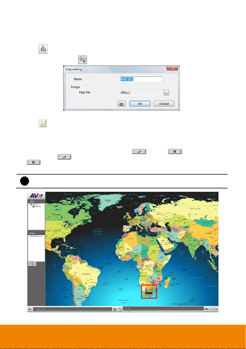
4.6.2 Add a New Map
1. Click Setup in SecureCenter main UI.
2. In the Authorization dialog box, enter the administrator User ID and Password
3. Click (E-Map Setting) button.
4. In E-Map interface, click button and the Map setting window will show up.
5. Give a name for the new map.
6. Click to locate the map file. In the open dialog box, locate and select the map and click
Open. Then, click OK button in Map setting dialog and a new map icon will display on the map.
7. User may now drag and move the new map icon to its place on the map.
8. User can double click the new map icon to view the map.
9. To edit and delete the map, click the map icon and (Edit) and (Delete) button will be
enabled. Click button to modify the map. To delete the map, click the map icon and click
button.
10. Click OK to accept the new setting and Cancel to exit without saving the new setting.
45
Page 51
Right-click on the NVR
server icon to call out
the short-curt menu.
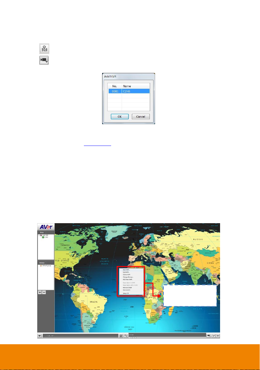
4.6.3 Add a NVR Server
1. Click Setup in SecureCenter main UI.
2. In the Authorization dialog box, enter the administrator User ID and Password
3. Click (E-Map Setting) button.
4. Click (Add NVR) button and the Add NVR window will show up.
5. Select the NVR server from the Add NVR window and click OK.
6. User may now drag and move the NVR icon to its place on the map.
7. Right-click the NVR server icon can call out a short-cut menu. User can click Edit NVR to modify
the NVR server (also see Chapter 4.2). To delete the NVR server from the map, click the Delete
NVR.
The functions of short-cut menu is listing below:
- Add NVR: To add a NVR server on the E-Map.
- Edit NVR: To modify the NVR server.
- Delete NVR: To delete the selected NVR server from the E-Map.
- Change Bitmap: Replace the E-Map with new map. The map file only support *.jpg and
*.bmp.
- Add New map: Add up a New map on current E-Map level.
- Remote EMAP: To view the selected remote NVR server’s E-map.
- Remote I/O: To view the selected remote NVR server’s I/O status.
- Setup OK: To save the changes of configuration.
46
Page 52

i
- If user uses dual monitor, the E-map setup window is displayed in the monitor that user
has set(also see Chapter 4.1).
- Click to exit the setup mode in E-Map interface.
The tab will falsh
when NVR server has
alarm triggered and
list which map and
NVR server has
alarms.
4.6.4 To Use the E-Map
When the alarm has been activated, the NVR icon blinks and turns red.
1. On the SecureCenter main UI, click E-map or press F3.
2. When the NVR server has an alarm occurred, use the mouse to point on the NVR server icon
and the alarm information will show up.
3. To stop the NVR server icon from blinking, right-click and select Reset Alarm in CMS or Reset
Alarm (all) in CMS. The NVR server icon will stop blinking.
4. In E-map UI, click button to back to the SecureCenter main UI.
5. To switch to E-Map setup mode, click button or right-click the NVR server and select E-Map
setup (see also Chapter 4.6.1).
6. User can click the Map icon on the map to view the map.
7. Click the NVR server icon and a NVR watch window will show up and connect the NVR server to
display the live video.
8. In NVR watch UI, click can call out PTZ control panel if the PTZ camera is available. Also,
click can enable/disable the audio, but only one channel at a time can play the audio. The
green audio icon indicates that the channel is playing audio now. To exit NVR watch, click
button to back to E-map UI.
47
Page 53

i
Right-click on channel screen can select Remote I/O selection to view the channel I/O
and edit relay status.
NVR Watch UI
48
Page 54
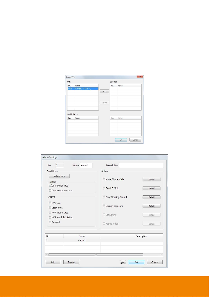
4.7 Alarm Setting
In the Alarm Setting dialog box, just select and enable the condition for the system to alarm and the
action for the system to perform when an alarm is activated. User can setup a total of 16 different
combinations of alarm settings. Each alarm setting can apply to several NVR servers. Click OK to
accept new setting and Cancel to exit without saving.
4.7.1 To setup an alarm condition
1. Click the Add button to add a new alarm condition.
2. Give the name of this alarm condition.
3. Fill the simply description of this alarm condition in Description column.
4. Apply to the NVR server, click Select NVR. In Select NVR window, select the NVR server and
click Add. To exit and save the setup, click OK.
5. Select the Conditions.
6. Select the Action(see 4.7.1.1 & 4.7.1.2 & 4.7.1.3 & 4.7.1.4 & 4.7.1.5 & 4.7.1.6).
7. Click OK to save the setting. To cancel click Cancel.
49
Page 55
i
To use make phone call function, please make sure you deselect the option "wait for dial
tone before dialing" in modem properties in control panel of your Windows OS.
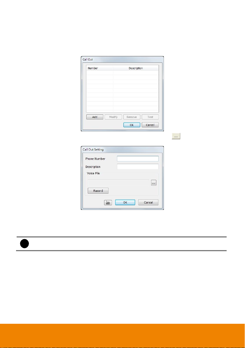
4.7.1.1 To Setup the Call Out List
To use this feature, the PC must have a voice modem connected to it. The supported audio system is
only 8KHz and 16Bit mono.
1. Next to the Make Phone Calls check box, click Detail.
2. In the Call Out List, click Add to insert a new contact number, Modify to edit the selected item,
Remove to delete the selected item, Test to check if it is working.
3. In the Call Out Setting, enter the phone number and description. Click to select existing
recorded sound and click Record to make a new voice message.
4. When the Sound Recorder appears, use the record control panel to record, stop, play, rewind
and forward. If you want to keep the existing file, click File > Save As…, enter filename and
click Save. Make sure you have microphone connected to your PC.
5. Click OK to exit and accept the setting and click Cancel to exit without saving the setting.
50
Page 56
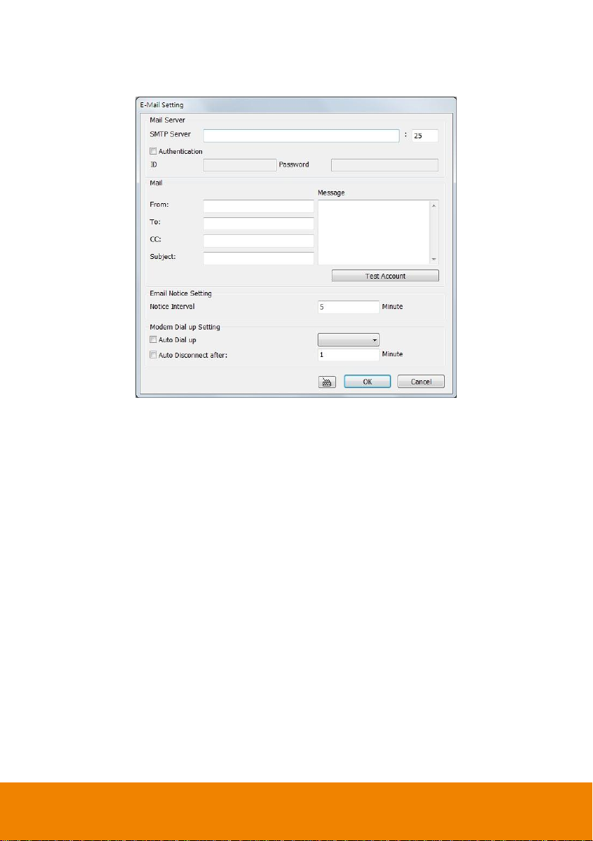
4.7.1.2 To Setup the Send E-Mail Setting
Next to the Send Email check box, click Detail. In the E-mail Setting dialog box, click OK to exit and
save the setting and Cancel to exit without saving the setting.
Mail Server
Enter the SMTP Server and port. If your e-mail system requires user identification, enable the
Authentication check box and enter User ID and Password.
Mail
To check if it is working, click the Test Account button.
From: Enter the sender e-mail address.
To and CC: Enter the recipient email address and separate it with comma or a semicolon (;).
Subject: Enter the message title.
Message: Type the message.
Email Notice Setting
In the Notice Interval text box, set the period of time before it sends another e-mail notice.
Modem Dial up Setting
If you are using dial up modem, enable Auto Dial up check box and select the modem name. You
may also set the time to disconnect automatically, just enable the Auto Disconnect after check box
and set the time.
51
Page 57

4.7.1.3 To Setup the Alarm Sound Setting
1. Next to the Play Warning Sound check box, click Detail.
2. In the Alarm Sound Setting dialog box, click to select other wav file from other source or folder,
Play to listen, Record to make a new copy of a sound.
3. Select the Play Mode.
Interrupt: when receive the new alarm warming, immediately play new warming sound.
Play by sequence: when receive the new alarm warming, play after the on playing alarm
warming.
4. If you click Record, you will be prompted if you want to replace the file. Click OK to continue and
Cancel to discontinue.
5. When the Sound Recorder appears, use the record control panel to record, stop, play, rewind and
forward. If you want to keep the existing file, click File > Save As…, enter filename and click Save.
Make sure you have microphone connected to your PC.
6. Click OK to exit and accept the setting and Cancel to exit without saving the setting.
4.7.1.4 Launch program
To call up the external program that is provided by a 3rd party. Click Detail and click to locate the
program path. Enable the Multiple instance check box if the external application has been
programmed to execute repeatedly.
52
Page 58

i
The incorrect pin code will lock your sim card.
4.7.1.5 To Set the MMS/SMS Setting
To use this feature, GSM/GPRS modem is required. Connect the GSM/GPRS modem to the serial
COMM port of PC. Next to the SMS/MMS check box, click Detail.
1. Select the port number in ComPort drop down list from where the GSM/GPRS modem is
connected.
2. Click Enter Pincode button to fill in pin code of your mobile phone if your mobile system require
verifying pin code for SMS/MMS sending.
3. In Phone Num text box, enter the contact number.
4. You may now set to send thru SMS or MMS. If you enable SMS setting, just enter the message
in the Message Text box. Click SMS Test to verify the SMS setup is available.
5. If you enable MMS, enter the Loing account, Password, APN name, WAP IP, MMS address,
subject of MMS message and the message. User can Import the previous MMS setting or
Export the current MMS setting. If you are not sure, please contact your mobile service provider.
To verify the setting, click MMS Test.
6. Click OK to accept the new settings and Cancel to exit without saving.
53
Page 59
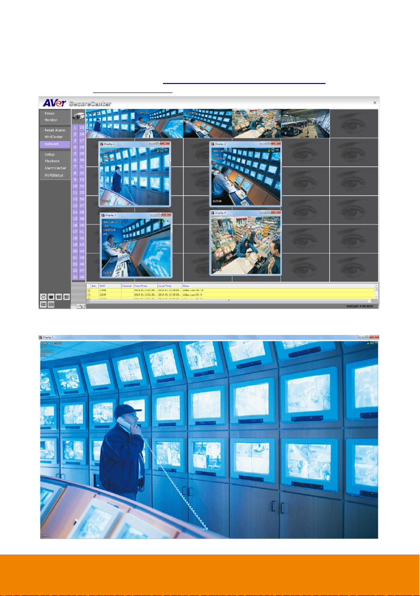
4.7.1.6 Popup Video
The Popup video will co-work with alarm condition of Receive Alarm. When user selects the alarm
condition of Receive Alarm, and then the action of Popup video will be un-gray and available for select.
The popup video has 2 way of displaying – 4-split alarm display and one full screen alarm display (To
select the alarm display mode, go to Chapter 4.1 System Setting (9)Alarm Display). To setup Popup
video, please see To Setup Popup Video.
4-split Alarm Display window mode
Single Screen Alarm Display mode
54
Page 60

On the upper right corner of popup video window, there two figures that are to represent nailed popup
video window and mini center function. To close popup video window, just click “X” of window.
(a) To call out NVR watch window.
(b) To nail popup video window for avoiding new coming alarm video to replace it.
(c) To call out MiniCenter(also see Chapter 3.4)
(d) Alarm number for static view alarm video. Alarm type and channel for live video alarm.
(e) NVR name.
(f) NVR’s IP address.
(g) Camera channel of NVR server.
(h) Time of alarm has received.
To Setup Popup Video
1. In Alarm setting window, Click Detail of popup video.
2. Select the type of popup video
- Static View: The NVR server only transmits one frame of video and popup on
SecureCenter site.
- Live View: The NVR server will continue to transmit video to SecureCenter site while
3. Click OK to save the setting.
popup video window is open.
55
Page 61

Click it to select the
NVR for user to view.
Click it to select the
Monitor for user to
view.
4.8 User Setting
SecureCenter supports 256 user account that includes operator and administrator account.
1. Select the Authorization Level – Operator or Administrator. User can define each
operator/administrator account’s authority of NVR server and Monitor set. Only the
administrator is authorized to close and customize the SecureCenter system.
2. Enter the Name, Description, Password, and Confirm password of the account.
3. Select the NVR servers that allow this account user to preview and playback. The NVR server
with check mark means is selected.
4. Select the Monitor set that allow this account user to view. The Monitor set with check mark
means is selected.
5. User can assign a valid date for Operator user. Select Begin Date and End Date to assign a
valid date for operator account. The account only will be available during the assigned date.
6. Click OK to accept the new settings and Cancel to exit without saving.
56
Page 62

Chapter 5 Using the Playback Function
User can choose to playback video stored on the local hard disk or download the video from the
remote side of the NVR server.
5.1 To Playback the video
1. Click Playback in SecureCenter main UI.
2. In the NVR Playback select window, select NVR server to play video from the remote NVR server.
3. You can select Local Playback, Download and playback or RealTime playback. Click OK to
proceed and Cancel to void this operation.
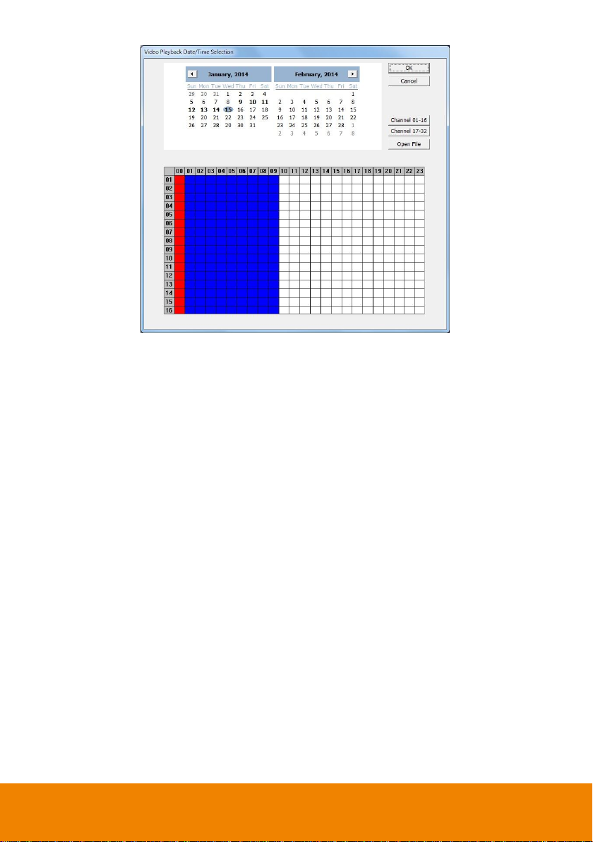
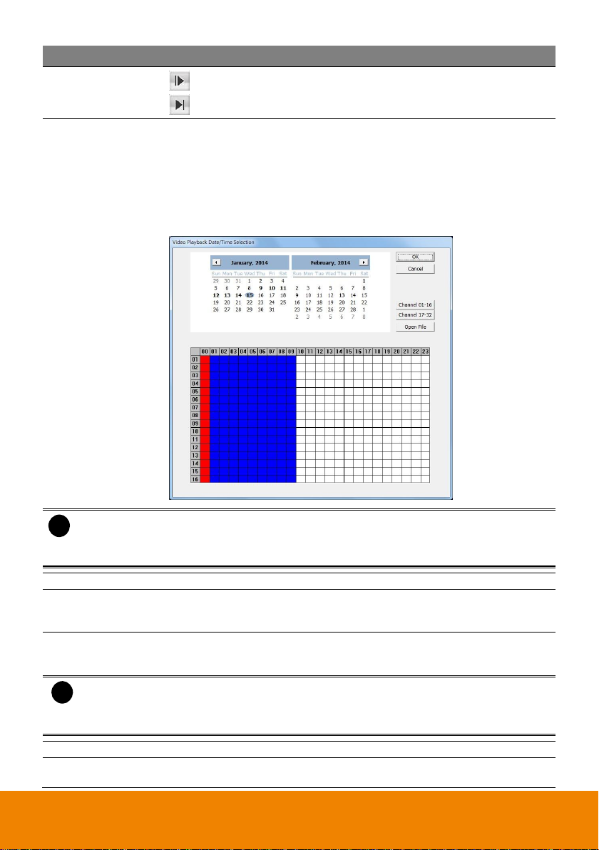
4. For Local Playback, user can select to preview 16 channels at a time. Only the cameras previously
selected in Monitor and with the Record enabled can be playback. In the Video Playback
Date/Time Selection, the numbers from 00 to 23 represent the time in 24-hour. The numbers from
01 to 16 represent the camera number. The blue block indicates that there is a recorded video file
in that period of time. While the red bar indicates the selected recorded video for viewing (see also
Chapter 5.2).
57
Page 63

5. For Download and Playback, the numbers from 00 to 23 represent the time in 24-hour in the
Remote Playback Date/Time Selection window. The numbers from 01 to 16 represent the camera
number. The blue block indicates that there is a recorded video file on that period of time. While
the red block indicates the selected recorded video for viewing.
6. In the Time Selection screen, click on the video thumbnail you want to download and open (see
also Chapter 5.3 ).
7. For RealTime Playback, the number from 00 to 23 represent the time in 24-hour clock in the Video
Playback Date/Time Selection window. The numbers from 01 to 16 represent the camera
number.(see also Chapter 5.4)
58
Page 64
59
Page 65

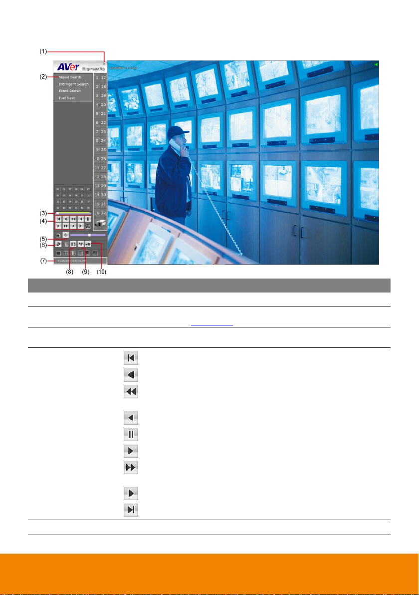
Name
Function
(1) Exit
Close the Player.
(2) Visual Search
Search from a specific camera by Date, Hour, Minute, 10 Seconds and
Second (See also Chapter 5.5).
(3) Intelligent Search
Search the changes in the motion detector frame (See also Chapter 5.6).
(4) Event Search
Search from the recorded activities that take place in the system (i.e.,
Sensor, Motion, Video Loss) (See also Chapter 5.7).
(5) Find Next
Search for the next event or changes in the motion detector frame. You
can use this when you are using Intelligent Search or Event Search only.
(6) Camera ID
Show the number of cameras that are being viewed. When you are in
single screen mode, click the camera ID number to switch and view other
camera.
(7) Hour Buttons
Select and click to playback the recorded video file on the specific time
frame.
i
The numbers from 00 to 23 represent the time in 24-hour clock. The blue colored
indicates that there is a recorded video file on that period of time. While the red colored
column indicates on where to start playing the recorded video file.
(8) Progress bar
Show the progress of the file being played. You may move the bar to seek
at any location of the track.
(9) Playback Control
Buttons
(Begin): Move to the beginning of the recorded video file.
(Previous): Go back to the previous frame.
(Slower): Play the recorded video file at the speed of 1/2x, 1/4x, or
1/8x, 1/16x, or 1/32x.
5.2 Using the Local Playback Application
60
Page 66
Name
Function
(9) Playback Control
Buttons
(Rewind): Wind back the recorded video file.
(Pause): Briefly stop playing the recorded video file.
(Play): Play the recorded video file.
(Faster): Play the recorded video file at the speed of 2x, 4x, 8x, 16x,
or 32x.
(Next): Go to the next frame.
(End): Go to the end of the recorded video file.
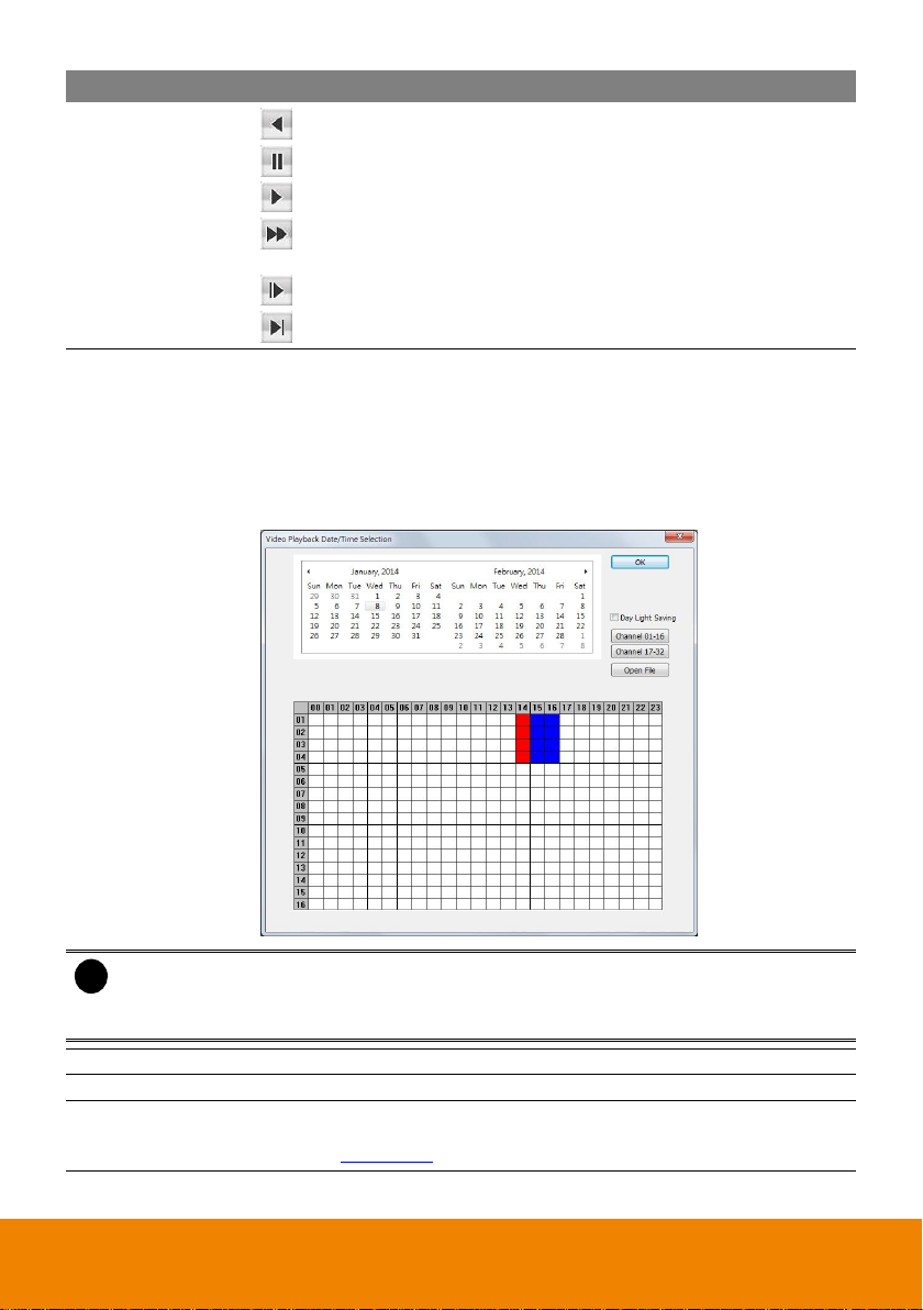
(10) Date Selection
Select the date on the calendar and the time from 00 to 23 to where to
start playing the recorded video file.
– Also, user can open the recorded file from certain location by click
OPEN FILE button
– Click Channel 01~ 16 and Channel 17 ~ 32 button to switch to
different channel group of playback calendar.
– Mark Day Light Saving, the playback calendar will show the available
playback records during day light saving period.
i
The numbers from 00 to 23 represent the time in 24-hour clock. The numbers from 01 to
16 represent the camera ID. The blue colored column indicates that there is a recorded
video file on that period of time. While the red colored column indicates on where to start
playing the recorded video file.
(11) Watermark
To verify the playback video has not been modified.
(12) Audio
Enable/disable audio and adjust volume
(13) Bookmark
Mark a reference point when previewing the recorded video file to which
you may return for later reference. You may also set it to protect the file.
(See also Chapter 5.8)
61
Page 67

Name
Function
(14) Event Log
Show the record of activities that take place in the system. To filter the
records, select and click the option button to only display Event, System,
Operation, or Network.
(15) Status bar
Display the recorded date, time and play speed.
(16) Full screen
View in full screen mode. To return, Right click the mouse or press ESC
on the keyboard.
(17) Split Screen
Mode
Select from six (6) different split screen types to playback the recorded
video file of all the cameras, or one camera over the other or alongside on
a single screen.
i
- To zoom into an area on the screen, Right click and Drag a square on the area you
want to enlarge.
- To view 32 channels, click 16 split screen mode button to view 16 channels each time.
Check the camera ID icon to know which channels are displaying now.
(18) Export
Export includes Snapshot, Print, and Output Video Clip function.
Snapshot: Capture and save the screen shot either in *.jpg or *.bmp
format.
Print: Print the screen shot.
Output Video Clip: Save the segmented file in *.mpg, *.avi, or *.dvr
format (see also Chapter 5.9).
(19) Segment
Keep a portion of the recorded video you want (see also Chapter 5.9).
62
Page 68
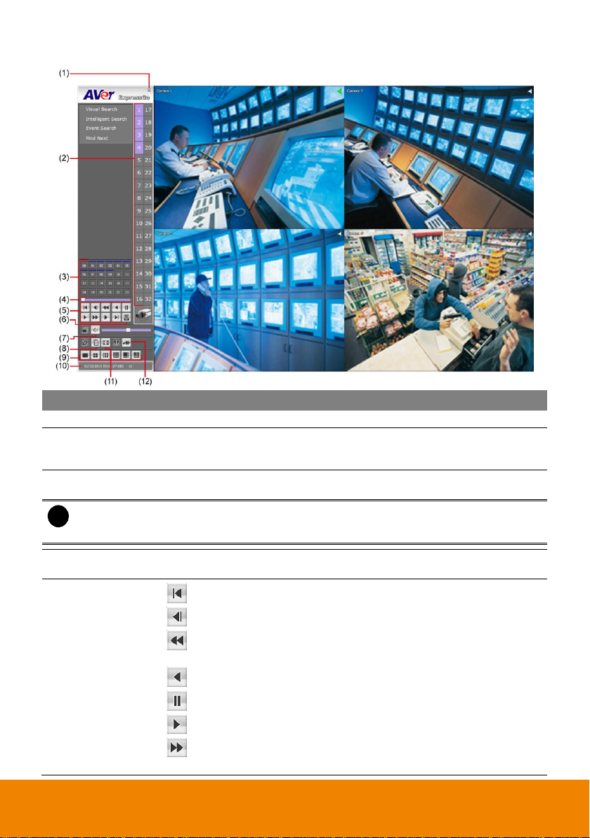
Name
Function
(1) Exit
Close the player
(2) Visual Search
Search from a specific camera by Date, Hour, Minute, 10 Seconds and
Second. (See also Chapter 5.5)
(3) Progress bar
Show the progress of the file being played. You may move the bar to seek
at any location of the track.
(4) Playback Control
Buttons
(Begin): Move to the beginning of the recorded video file.
(Previous): Go back to the previous frame.
(Slower): Play the recorded video file at the speed of 1/2x, 1/4x, or
1/8x, 1/16x, or 1/32x.
(Rewind): Wind back the recorded video file.
(Pause): Briefly stop playing the recorded video file.
(Play): Play the recorded video file.
(Faster): Play the recorded video file at the speed of 2x, 4x, 8x, 16x,
or 32x.
(Next): Go to the next frame.
(End): Go to the end of the recorded video file.
(5) Audio
Enable/disable audio and adjust volume
5.3 Using the Download and Playback Application
63
Page 69

Name
Function
(6) Bookmark
Mark a reference point when previewing the recorded video file to which
you may return for later reference. You may also set it to protect the file.
(See also Chapter 5.8)
(7) Status bar
Display the recorded date, time and play speed.
(8) Full screen
View in full screen mode. To return, press the right button of the mouse or
ESC on the keyboard.
(9) Segment
Keep a portion of the recorded video you want. You may follow the
instruction in Chapter 5.9.
(10) Export
Export includes Snapshot, Print, and Output Video Clip function.
Snapshot: Capture and save the screen shot either in *.jpg or *.bmp
format.
Print: Print the screen shot.
Output Video Clip: Save the segmented file in *.mpg, *.avi, or *.dvr
format (see also Chapter 5.9).
64
Page 70
Name
Function
(1) Exit
Close the Player.
(2) Camera ID
Show the number of cameras that are being viewed. When you are in
single screen mode, click the camera ID number to switch and view other
camera.
(3) Hour Buttons
Select and click to playback the recorded video file on the specific time
frame.
i
The numbers from 00 to 23 represent the time in 24-hour clock. The blue colored
indicates that there is a recorded video file on that period of time. While the red colored
column indicates on where to start playing the recorded video file.
(4) Progress bar
Show the progress of the file being played. You may move the bar to seek
at any location of the track.
(5) Playback Control
Buttons
(Begin): Move to the beginning of the recorded video file.
(Previous): Go back to the previous frame.
(Slower): Play the recorded video file at the speed of 1/2x, 1/4x, or
1/8x, 1/16x, or 1/32x.
(Rewind): Wind back the recorded video file.
(Pause): Briefly stop playing the recorded video file.
(Play): Play the recorded video file.
(Faster): Play the recorded video file at the speed of 2x, 4x, 8x, 16x,
or 32x.
5.4 Using the RealTime Playback Application
65
Page 71
Name
Function
(5) Playback Control
Buttons
(Next): Go to the next frame.
(End): Go to the end of the recorded video file.
(6) Date Selection
Select the date on the calendar and the time from 00 to 23 to where to
start playing the recorded video file.
– Also, user can open the recorded file from certain location by click
OPEN FILE button
– Click Channel 01~ 16 and Channel 17 ~ 32 button to switch to
different channel group of playback calendar.
– Mark Day Light Saving, the playback calendar will show the available
playback records during day light saving period.
i
The numbers from 00 to 23 represent the time in 24-hour clock. The numbers from 01 to
16 represent the camera ID. The blue colored column indicates that there is a recorded
video file on that period of time. While the red colored column indicates on where to start
playing the recorded video file.
(7) Audio
Enable/disable audio and adjust volume
(8) Event Log
Show the record of activities that take place in the system. To filter the
records, select and click the option button to only display Event, System,
Operation, or Network.
(9) Split Screen
Mode
Select from six (6) different split screen types to playback the recorded
video file of all the cameras, or one camera over the other or alongside on
a single screen.
i
- To zoom into an area on the screen, Right click and Drag a square on the area you
want to enlarge.
- To view 32 channels, click 16 split screen mode button to view 16 channels each time.
Check the camera ID icon to know which channels are displaying now.
(10) Status bar
Display the recorded date, time and play speed.
(11) Full screen
View in full screen mode. To return, Right click the mouse or press ESC
on the keyboard.
66
Page 72
Name
Function
(12) Export
Snapshot: Capture and save the screen shot either in *.jpg or *.bmp
format.
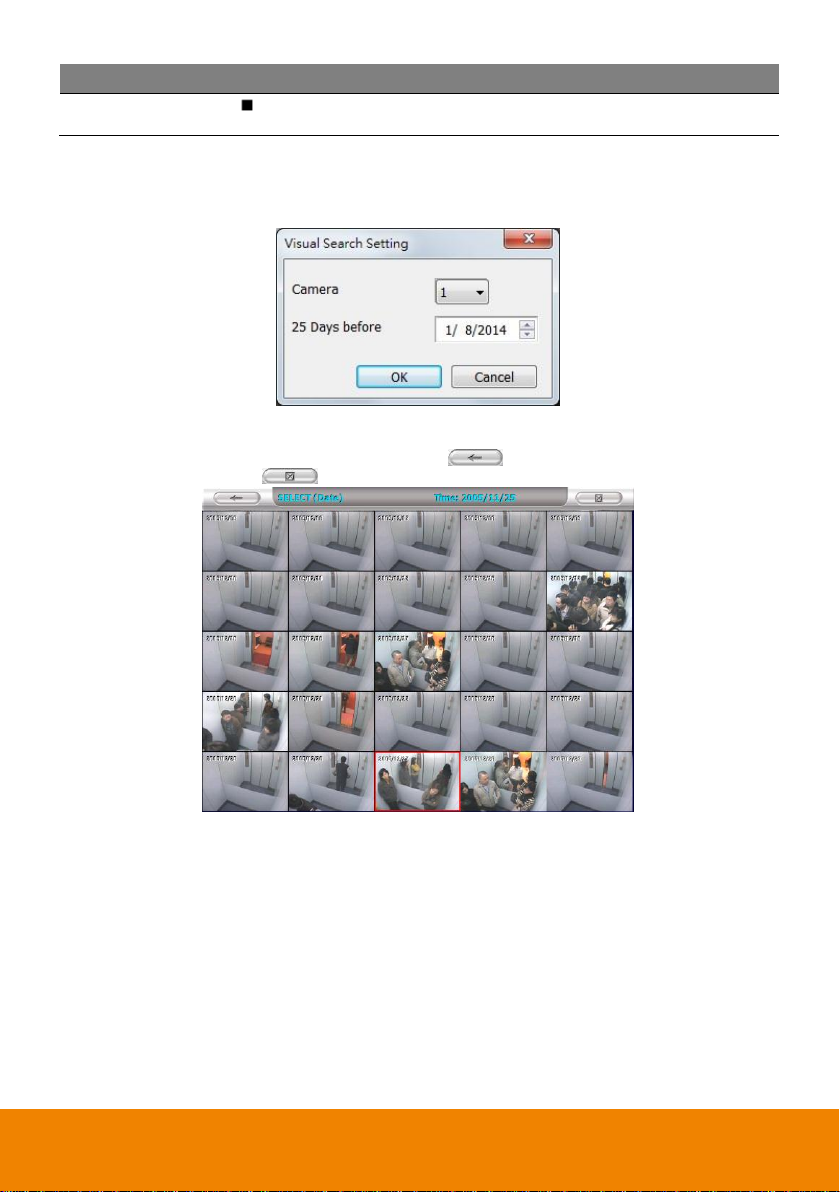
5.5 To Search Using the Visual Search
1. Click Visual Search.
2. In the Visual Search Setting dialog box, select the Camera number and the date. Then click OK.
3. When a series of frames appear by date, click on the frame to display another series of frames
and search by every Hour of that date, every Minute of that hour, every 10 Seconds of that minute,
every Second of that 10 seconds. To go back, click . To view from the selected frame and
close event search, click .
67
Page 73

5.6 To Search Using the Intelligent Search
1. Click on the video screen on where you want to search.
2. Click Intelligent Search. The Intelligent Search text (red) would appear at the lower left corner
of the screen.
3. When the Intelligent Search Setting dialog box and motion detector frame appear, you may adjust
the sensitivity bar and the motion detector frame size and location. To set motion detector frame
size and location, left click and drag on the screen. Then, click OK to start searching. The video
search would stop at the frame that matches the condition. To keep on searching, click Find Next.
4. You may also set to search and list all the result. Just check the List box. In the Search Duration
section, set the Begin Time, End Time and Searching Interval. Then, click OK to start searching.
68
Page 74

5.7 To Search Using the Event Search
1. Click on the video screen on where you want to search.
2. Click Event Search. The Event Search text (red) would appear at the lower left corner of the
screen.
3. In the Event Search Setting dialog box, check the type of condition you want to search. The
video search would stop at the frame that matches the condition. To keep on searching, click Find
Next.
4. You may also set to search and list all the result. Just check the Output Event List box. In the
Search Duration section, set the Begin Time, End Time and Searching Interval. Then, click OK
to start searching.
5. When the Event list appears, click and select the item you want to view.
69
Page 75
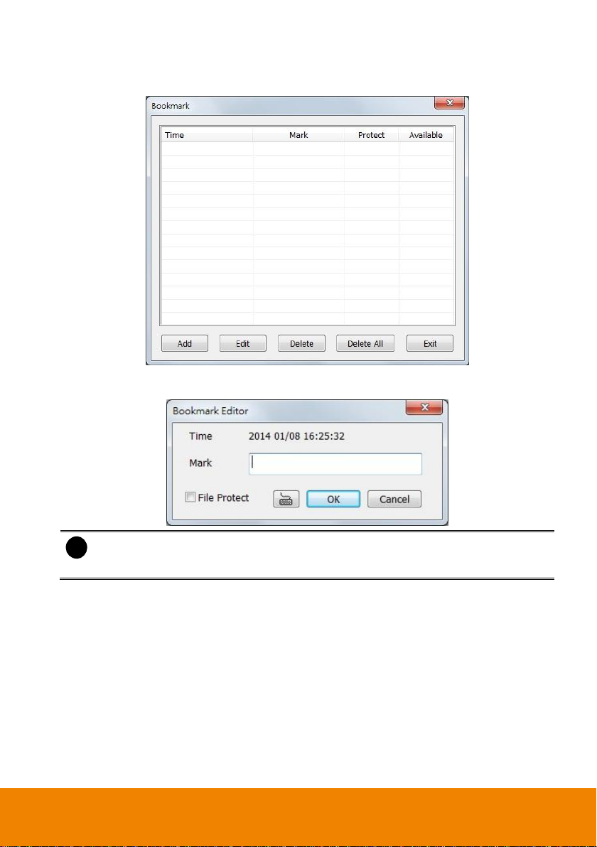
i
- When the bookmark is protected, the file won’t be overwritten.
- The protected bookmark file will be deleted when the Delete the recorded data is
enable in the Backup setting.
5.8 To Bookmark a Section of the Video
1. Click Bookmark. The video playback stops when the bookmark button is executed.
2. In the Bookmark dialog box, you may do the following:
- Add to include the new reference mark in the bookmark list. You may select to
enable/disable File Protect to protect the bookmark file for overwritten.
- Edit to change the mark description or enable/disable file protection.
- Delete to remove the selected reference mark in the list.
- Delete All to remove all the reference marks in the list.
- Exit to close Bookmark dialog box.
3. Select and click one in the bookmark list to preview the file.
70
Page 76

5.9 To Cut and Save the Wanted Portion of the Recorded Video
1. Use the Playback Control buttons or drag the bar on the playback progress bar and pause on
where you want to start the cut. Then, click button to set the begin mark.
2. Use the Playback Control buttons or drag the bar on the playback progress bar and pause on
where you want to end the cut. Then, click button to set the end mark. To cancel
segmentation or set the segment marks from the start, click button again.
3. Click Output button to save the wanted clip.
4. In the Save As dialog box, locate on where you want to save the file, type the filename, and select
the video format.
71
 Loading...