

Page 1

SD1306
Speed Dome IP Camera
Quick User Guide
Page 2

Table of Contents
I. Camera Introduction ........................................................................................ 1
1. Package Contents ................................................................................... 1
2. Hardware Installation ............................................................................... 2
2.1 Factory Default ................................................................................... 6
3. SD card Compatibility List ....................................................................... 7
II. Monitor Setting ................................................................................................ 8
III. IP Assignment ................................................................................................. 9
Finding IP Camera by using “NXU Lite recording software” .............................. 9
Finding IP Camera by using “AVer IPCam Utility”............................................ 12
Using NON-DHCP Server/Router Network...................................................... 14
IV. Connecting the IP Camera ............................................................................ 16
COPYRIGHT ......................................................................................................... 17
NOTICE ................................................................................................................. 17
WARNING ............................................................................................................. 17
Limited Warranty ................................................................................................. 18
Governing Law and Your Rights........................................................................ 19
Page 3
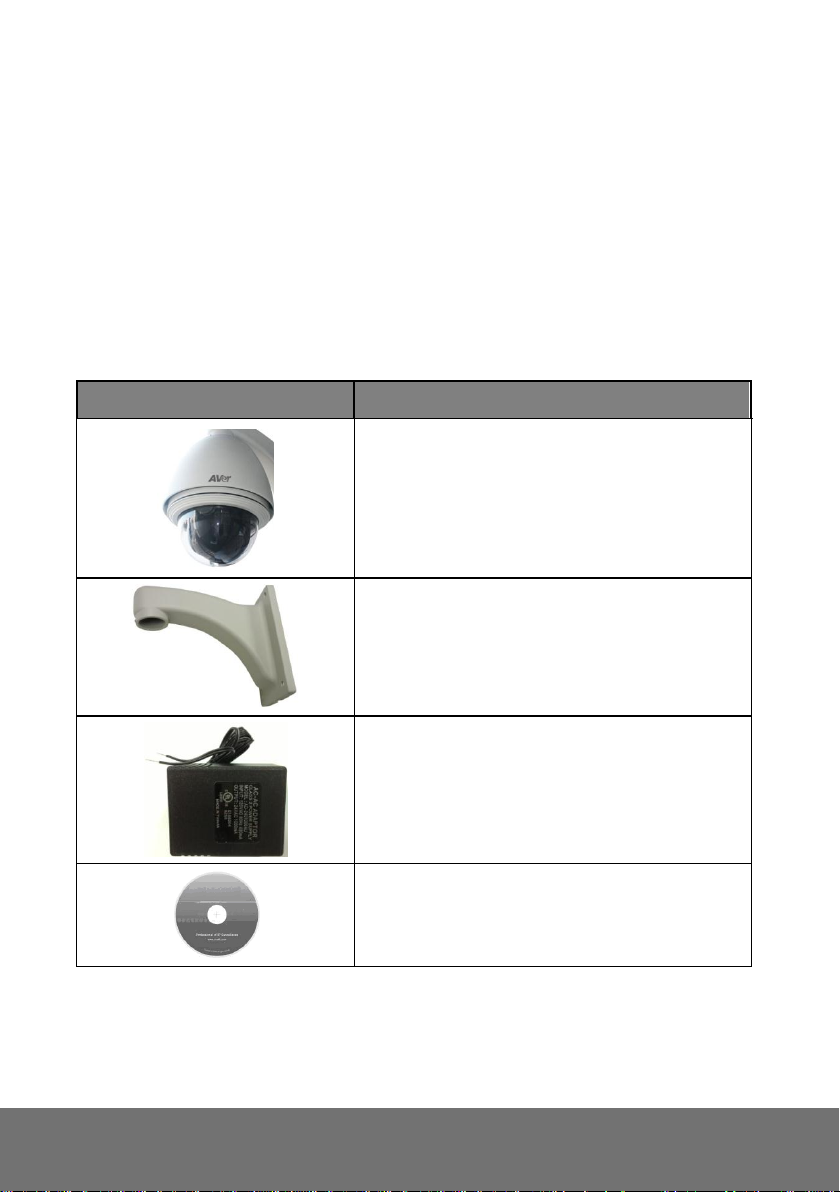
Item
Descriptions
1. SD1306
2. Wall mount
3. Power Adaptor (AC 24V/1A) (optional item.)
4. CD (User’s Manual and Quick Guide, NVR
software included)
Before Installation
Before installation, please be sure to read this quick installation guide and user’s manual carefully to
complete the installation.
I. Camera Introduction
The following section introduces package contents, hardware installation, factory default reset, and SD
card Compatibility List of each type camera.
1. Package Contents
**If any of the above items are missing, please contact your dealer immediately.
1
Page 4
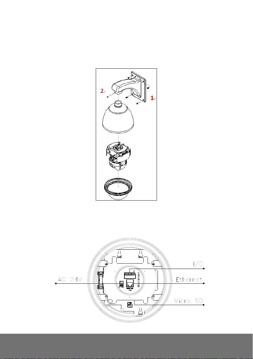
2. Hardware Installation
1. Install SD1306 with wall mount
Step 1: Install the base on the wall.
Step 2: Install the camera with wall mount pipe.
2. Connector Instruction
The camera connectors are as below. Connect the power and the Ethernet cable with the camera,
and set it according to your network environment.
2
Page 5
I/O port
Ethernet
Power adapter jack
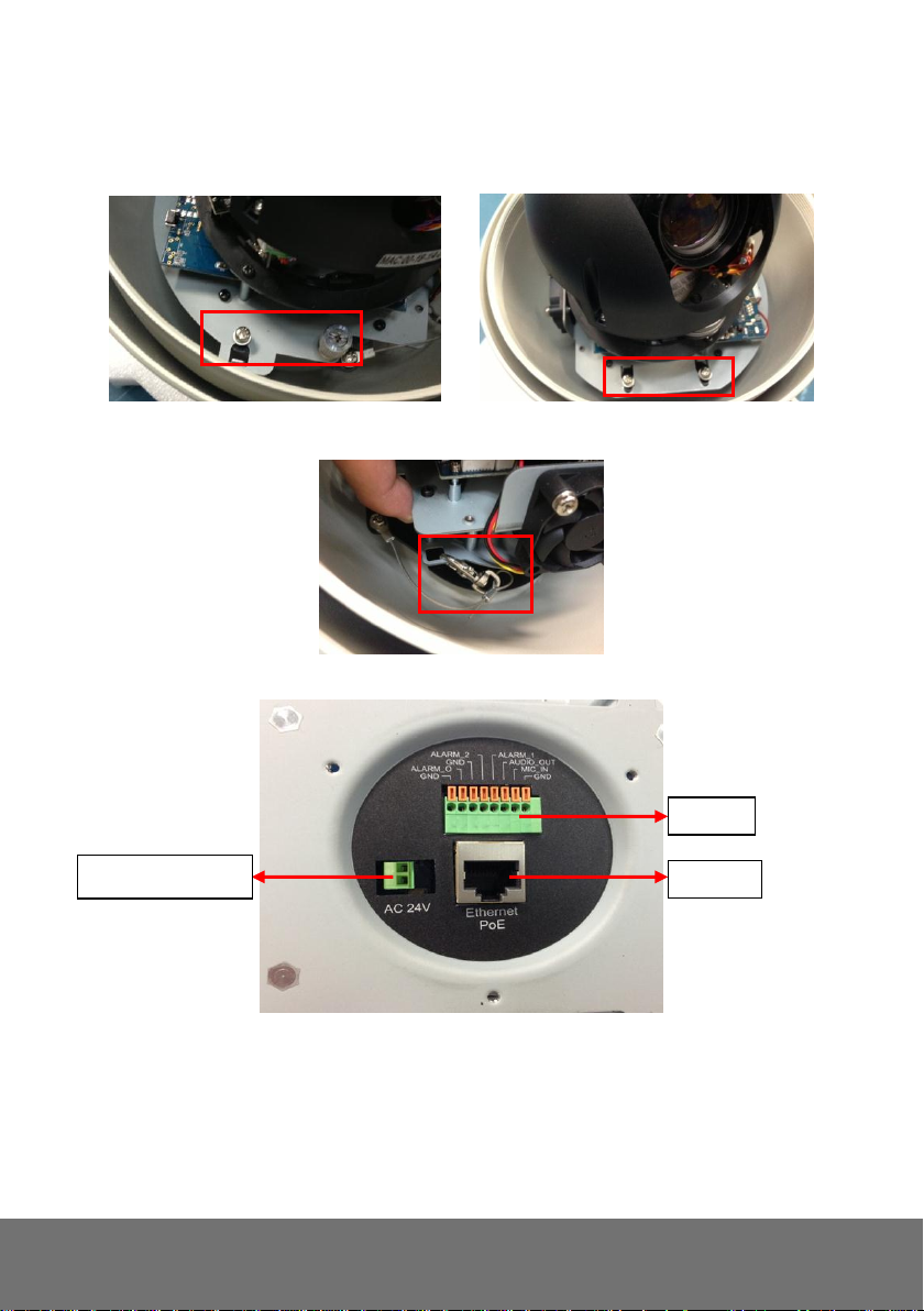
3. Instruction to remove cameral module from camera housing and install cables
i. Unscrew the screws on the four corners.
ii. Release the lock to move the whole camera module from the housing
iii. Finally, you can connect the Ethernet cable or DI.DO ports.
3
Page 6
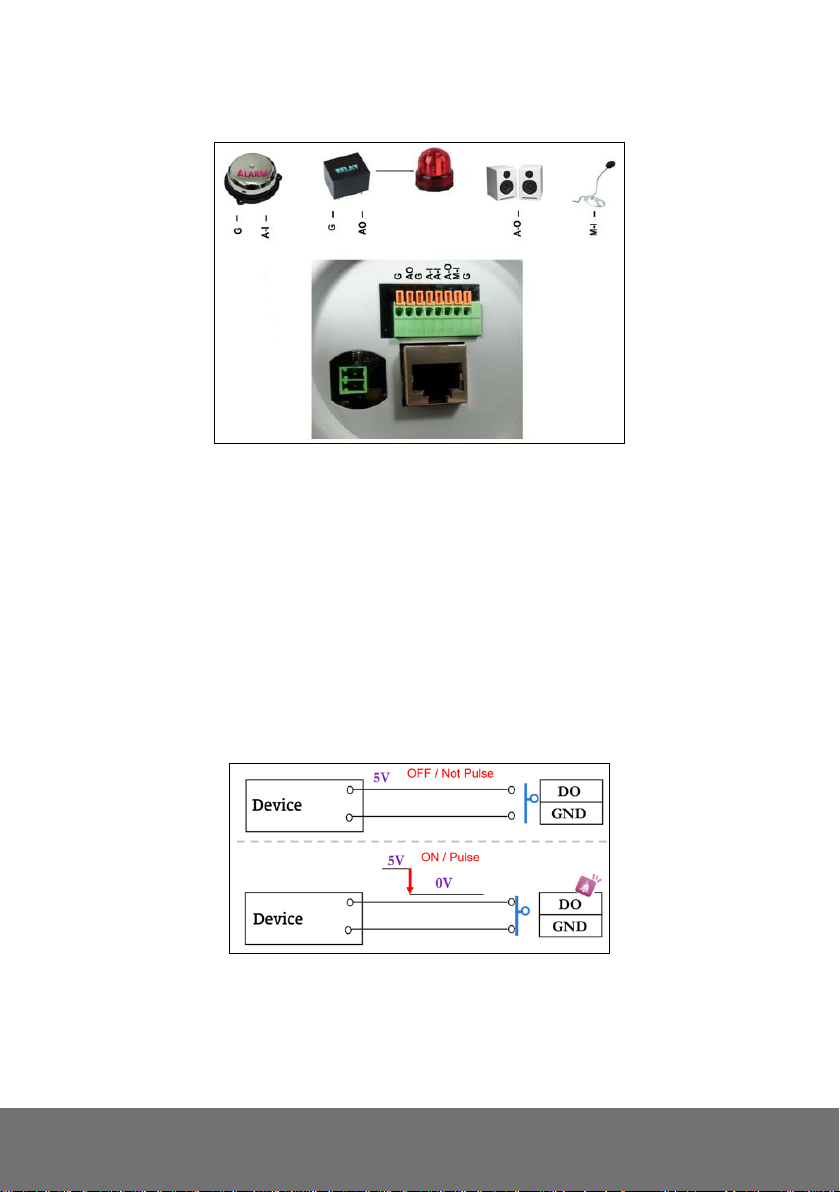
4. I/O Configuration
I/O Connection
a. Please connect the G & AO pin to the external relay (buzzer) device.
b. Please connect the G & A-I pin to the external trigger device.
c. I/O PIN definition.
G (Ground, GND)
AO (Digital Output, DO): DC 5V, initial state is High
A-I (Digital Input, DI): Max. 50mA, DC 5V, initial state is High
A-O Audio Output
M-I Microphone Input
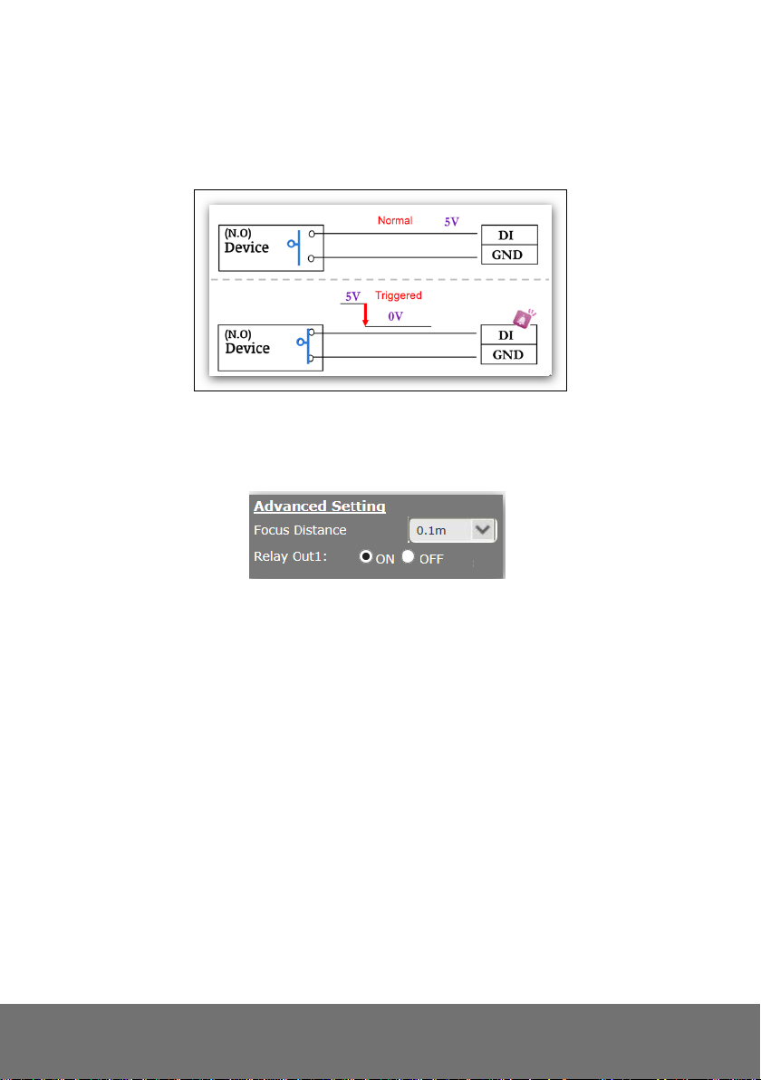
When no event happens, DO output is 5V (DO and GND are disconnected). When the camera
detects event happening and triggers external alarm, DO output is 0V (DO and GND are
connected).
If you select "N.O" in "Input sensor setting", when external device or circuit makes DI and GND
pin connected, the camera input alarm is triggered, and then camera will execute the action
user has set, for example, send snapshot to E-mail address.
4
Page 7
If you select "N.C" in "Input sensor setting", when external device or circuit makes DI and GND
pin disconnected, the camera input alarm is triggered, and then camera will execute the action
user has set, for example, send snapshot to E-mail address.
I/O Set up
Click I/O Setting from the system setup page via IE, and check “ON” on “Out1” to enable I/O
signal.
5
Page 8

2.1 Factory Default
1. To recover the default IP address and password, please follow the following steps.
2. Remove power and Ethernet cable.
3. Press and hold the button and connect power and Ethernet cable to the camera again and hold for
round 20 seconds for system booting.
4. Release the button when camera finishes proceed.
5. Re-login the camera using the default IP (http://192.168.1.168) or DHCP, and user name (admin),
password (admin).
6
Page 9

MicroSD/SDHC card
Transcend SDHC class4 16GB
Transcend SD class4 16GB
Transcend SDHC class4 32GB
Transcend SD class4 32GB
Transcend SD class6 4GB
Transcend SDHC class6 4GB
Transcend SD class6 8GB
Transcend SDHC class6 8GB
Transcend SD class6 16GB
Transcend SDHC class6 16GB
Transcend SDHC class10 4GB
Transcend SDHC class10 8GB
Transcend SDHC class10 16GB
SanDisk SDHC class4 4GB
SanDisk SDHC class4 8GB
SanDisk SDHC class4 16GB
SanDisk SDHC class4 32GB
3. SD card Compatibility List
SD1306 is compliant with microSD/SDHC card and to ensure recording quality, and please use
memory cards over 2G and Class 4 above (Max. 32G)
7
Page 10

II. Monitor Setting
1. Right-click on the desktop. Select “ Properties”
2. Change “Color quality” to “Highest (32-bit)”.
8
Page 11

Click it to call out virtual
keyboard.
III. IP Assignment
There are two ways to find IP Camera:
Finding IP Camera by using “NXU Lite recording software”
Finding IP Camera by using “AVer IPCam Utility”
Finding IP Camera by using “NXU Lite recording software”
1. The NXU Lite software is in the attached software CD. Before launching it, please install the
software first. During the installing process, users will be required to input a User name and
Password for login NXU Lite system. Users can define the User name and Password as wishes.
Please refer to NXU Lite user manual for detailed installation instruction.
2. To run the application, double-click on your PC desktop or click Start > Programs > DVR >
NXU Lite. For security purpose, some of the features would require you to enter User name and
Password before it can be accessed. When the Authorization dialog box appears, key in your User
ID and Password. (If this is the first time, enter the one you have registered when installing the
software.
9
Page 12

3. Click “Setup” button.
4. Click “Add IPCam” button.
5. Select “IP Camera” item.
10
Page 13

Double-click the IP camera model that
user has purchased (ex: SD1306).
Please ignore ONVIF
protocol selection; NXU Lite
doesn’t support ONVIF
connection.
6. Enter the IP Camera’s ID and Password (default is admin/admin) and click “Auto Search” to find
camera.
7. In Search Result window, click it the IP camera model that user has purchased (Please ignore
ONVIF connection item); the camera is in red text that is configurable. User can double-click on
the camera is in red text and configure the IP camera’s setting; even the IP camera is not in the
same IP segment. Press “OK” to back to previous screen and press ”Connect” to start live view.
11
Page 14

Finding IP Camera by using “AVer IPCam Utility”
1. Use the software, “AVer IPCam Utility” to assign the IP address of the IP camera. The software is
in the attached software CD.
2. Run the IPCam Utility
3. Select the proper network adapter and click [Search] to begin searching.
4. Select and double click the IP camera you want to access. If you want to change the setting of the
selected IP camera, enter the user ID, correct password, and change the settings and then click
Apply button. This will change the setting and rescan the network again.
12
Page 15

Default ID: admin
Default Password: admin
5. The IE browser will open and direct you to IP camera login page. This requires IPViewer.ocx to run.
If the IE ActiveX warning message appears, click to allow running the add-on.
[Note]
The default IP address is: 192.168.1.168
The default ID and Password are both ”admin”.
It is not allowed to enter device name in Chinese and any other special characters (' " \ & ^).
Gateway number can’t be “0”.
IP camera device name should be less than 30 digits
13
Page 16

Using NON-DHCP Server/Router Network
In Non-DHCP server/router network, the static IP address must be assigned to the device each time
when adding another IP camera to the network; the default IP address of the current one must be
changed to avoid conflict.
Please make sure the Subnet of the PC’s IP address and the IP camera’s IP address are the same.
[Example]
The same Subnet:
IP camera IP address: 192.168.1.168
PC IP address: 192.168.1.100
Different Subnets:
IP camera IP address: 192.168.1.168
PC IP address: 192.168.2.100
To Change PC IP Address:
Control PanelNetwork ConnectionsLocal Area Connection PropertiesInternet Protocol
(TCP/IP) Properties
Please make sure your IP camera and PC have the same Subnet. If not, please change IP
camera subnet or PC IP subnet accordingly.
PC’s IP address:
14
Page 17

IP camera IP addresses:
A quick way to access remote monitoring is to double-click on a selected IP camera in “Camera Name
list” in AVer IPCam Utility. Then, the IE browser will open and connect to IP camera.
Then, please key in the default “ID” and “Password”, both of which are “admin”.
15
Page 18

IV. Connecting the IP Camera
Launch the Internet Explorer browser, type the IP address of the IP camera in the address field. It will
show the following dialogue box. Key-in the ”ID” and “Password”. The default ”ID” and “Password”
are both “admin”.
Once connected to the IP camera, the following program interface will appear.
16
Page 19

THE MARK OF CROSSED-OUT WHEELED BIN INDICATES THAT THIS
PRODUCT MUST NOT BE DISPOSED OF WITH YOUR OTHER HOUSEHOLD
WASTE. INSTEAD, YOU NEED TO DISPOSE OF THE WASTE EQUIPMENT BY
HANDING IT OVER TO A DESIGNATED COLLECTION POINT FOR THE
RECYCLING OF WASTE ELECTRICAL AND ELECTRONIC EQUIPMENT. FOR
MORE INFORMATION ABOUT WHERE TO DROP OFF YOUR WASTE
EQUIPMENT FOR RECYCLING, PLEASE CONTACT YOUR HOUSEHOLD
WASTE DISPOSAL SERVICE OR THE SHOP WHERE YOU PURCHASED THE
PRODUCT.
COPYRIGHT
© 2015 AVer Information Inc. All rights reserved.
All rights of this object belong to AVer Information Inc. Reproduced or transmitted in any form
or by any means without the prior written permission of AVer Information Inc. is prohibited. All
information or specifications are subject to change without prior notice. “AVer” is a trademark
owned by AVer Information Inc. Other trademarks used herein for description purpose only
belong to each of their companies.
NOTICE
SPECIFICATIONS ARE SUBJECT TO CHANGE WITHOUT PRIOR NOTICE. THE
INFORMATION CONTAINED HEREIN IS TO BE CONSIDERED FOR REFERENCE ONLY.
WARNING
TO REDUCE RISK OF FIRE OR ELECTRIC SHOCK, DO NOT EXPOSE THIS APPLIANCE TO
RAIN OR MOISTURE. WARRANTY VOID FOR ANY UNAUTHORIZED PRODUCT
MODIFICATION.
17
Page 20

Limited Warranty
AVer Information, Inc. (“AVer”) warrants that the applicable product (“Product”) substantially conforms
to AVer’s documentation for the product and that its manufacture and components are free of defects
in material and workmanship under normal use. “You” as used in this agreement means you
individually or the business entity on whose behalf you use or install the product, as applicable. This
limited warranty extends only to You as the original purchaser. Except for the foregoing, the Product is
provided “AS IS.” In no event does AVer warrant that You will be able to operate the Product without
problems or interruptions, or that the Product is suitable for your purposes. Your exclusive remedy
and the entire liability of AVer under this paragraph shall be, at AVer’s option, the repair or replacement
of the Product with the same or a comparable product. This warranty does not apply to (a) any Product
on which the serial number has been defaced, modified, or removed, or (b) cartons, cases, batteries,
cabinets, tapes, or accessories used with this product. This warranty does not apply to any Product
that has suffered damage, deterioration or malfunction due to (a) accident, abuse, misuse, neglect, fire,
water, lightning, or other acts of nature, commercial or industrial use, unauthorized product
modification or failure to follow instructions included with the Product, (b) misapplication of service by
someone other than the manufacturer’s representative, (c) any shipment damages (such claims must
be made with the carrier), or (d) any other causes that do not relate to a Product defect. The Warranty
Period of any repaired or replaced Product shall be the longer of (a) the original Warranty Period or (b)
thirty (30) days from the date of delivery of the repaired or replaced product.
Limitations of Warranty
AVer makes no warranties to any third party. You are responsible for all claims, damages, settlements,
expenses, and attorneys’ fees with respect to claims made against You as a result of Your use or
misuse of the Product. This warranty applies only if the Product is installed, operated, maintained, and
used in accordance with AVer specifications. Specifically, the warranties do not extend to any failure
caused by (i) accident, unusual physical, electrical, or electromagnetic stress, neglect or misuse, (ii)
fluctuations in electrical power beyond AVer specifications, (iii) use of the Product with any accessories
or options not furnished by AVer or its authorized agents, or (iv) installation, alteration, or repair of the
Product by anyone other than AVer or its authorized agents.
Disclaimer of Warranty
EXCEPT AS EXPRESSLY PROVIDED OTHERWISE HEREIN AND TO THE MAXIMUM EXTENT
PERMITTED BY APPLICABLE LAW, AVER DISCLAIMS ALL OTHER WARRANTIES WITH
RESPECT TO THE PRODUCT, WHETHER EXPRESS, IMPLIED, STATUTORY OR OTHERWISE,
INCLUDING WITHOUT LIMITATION, SATISFACTORY QUALITY, COURSE OF DEALING, TRADE
USAGE OR PRACTICE OR THE IMPLIED WARRANTIES OF MERCHANTABILITY, FITNESS FOR A
PARTICULAR PURPOSE OR NONINFRINGEMENT OF THIRD PARTY RIGHTS.
Limitation of Liability
IN NO EVENT SHALL AVER BE LIABLE FOR INDIRECT, INCIDENTAL, SPECIAL, EXEMPLARY,
PUNITIVE, OR CONSEQUENTIAL DAMAGES OF ANY NATURE INCLUDING, BUT NOT LIMITED
TO, LOSS OF PROFITS, DATA, REVENUE, PRODUCTION, OR USE, BUSINESS INTERRUPTION,
OR PROCUREMENT OF SUBSTITUTE GOODS OR SERVICES ARISING OUT OF OR IN
CONNECTION WITH THIS LIMITED WARRANTY, OR THE USE OR PERFORMANCE OF ANY
PRODUCT, WHETHER BASED ON CONTRACT OR TORT, INCLUDING NEGLIGENCE, OR ANY
OTHER LEGAL THEORY, EVEN IF AVER HAS ADVISED OF THE POSSIBILITY OF SUCH
DAMAGES. AVER’S TOTAL, AGGREGATE LIABILITY FOR DAMAGES OF ANY NATURE,
REGARDLESS OF FORM OF ACTION, SHALL IN NO EVENT EXCEED THE AMOUNT PAID BY
YOU TO AVER FOR THE SPECIFIC PRODUCT UPON WHICH LIABILITY IS BASED.
18
Page 21

Governing Law and Your Rights
This warranty gives you specific legal rights; You may also have other rights granted under state law.
These rights vary from state to state.
19
 Loading...