

Page 1
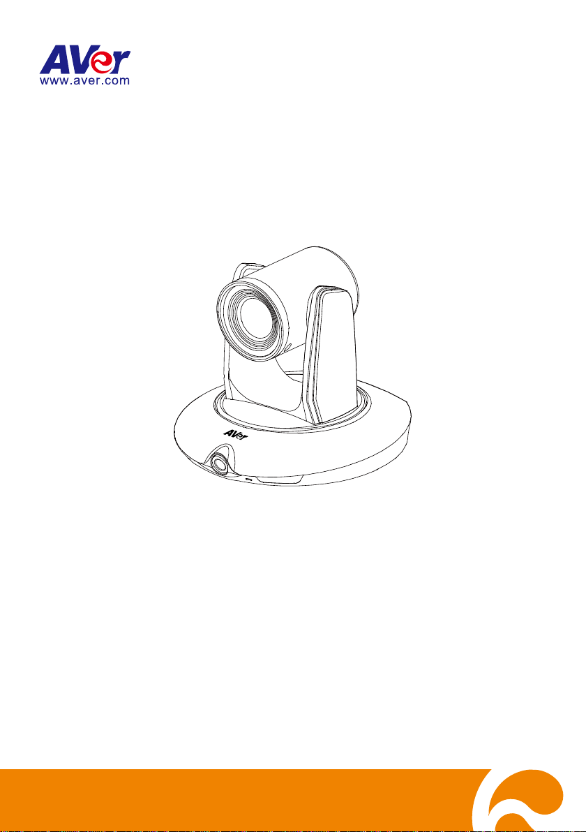
PTC500S
User Manual
V.1.0.1
Page 2
IMPORTANT NOTICE
PLEASE READ THE INSTRUCTIONS IN THIS MANUAL BEFORE INSTALLING THE PTC500S
TRACKING CAMERA.
DO NOT DISASSEMBLE OR MODIFY THE ITEMS BY YOURSELF. CONTACT THE DEALER
FOR HELP WHEN THE ITEMS IS FAILED TO WORK.
CONNECT THE DEVICES WITH PROPER CABLES.
TO REDUCE RISK OF ELECTRIC SHOCK ONLY USE INDOORS.
AVOID INSTALLING AT HUMID ENVIRONMENT.
Federal Communication Commission Interference Statement
NOTE: This equipment has been tested and found to comply with the limits for a Class A
digital device, pursuant to part 15 of the FCC Rules. These limits are designed to pro-vide
commercial environment. This equipment generates, uses, and can radiate radiofrequency energy and,
if not installed and used in accordance with the instruction manual, may cause harmful interference to
radio communications. Operation of this equipment in a residential area is likely to cause harmful
interference in which case the user will be required to correct the interference at his own expense.
FCC Caution: Any changes or modifications not expressly approved by the party responsible for
compliance could void the user's authority to operate this equipment.
This device complies with part 15 of the FCC Rules.
Operation is subject to the following two conditions:
(1) This device may not cause harmful interference, and
(2) this device must accept any interference received, including interference that may cause undesired
operation.
Warning: This is a class A product. In a domestic environment this product may cause radio
interference in which case the user may be required to take adequate measures
reasonable protection against harmful interference when the equipment is operate din a
European Community Compliance Statement (Class A)
This product is herewith confirmed to comply with the requirements set out in the Council
Directives on the Approximation of the laws of the Member States relating to
Electromagnetic Compatibility Directive 2014/30/EU.
Warning - This is a Class A product. In a domestic environment this product may cause radio
interference in which case the user may be required to take adequate measures to correct this
interference.
Page 3
The mark of Crossed-out wheeled bin indicates that this product must not be disposed
of with your other household waste. Instead, you need to dispose of the waste
equipment by handing it over to a designated collection point for the recycling of waste
electrical and electronic equipment. For more information about where to drop off your
waste equipment for recycling, please contact your household waste disposal service or
the shop where you purchased the product.
DISCLAIMER
No warranty or representation, either expressed or implied, is made with respect to the contents of this
documentation, its quality, performance, merchantability, or fitness for a particular purpose. Information
presented in this documentation has been carefully checked for reliability; however, no responsibility is
assumed for inaccuracies. The information contained in this documentation is subject to change without
notice.
In no event will AVer Information Inc. be liable for direct, indirect, special, incidental, or consequential
damages arising out of the use or inability to use this product or documentation, even if advised of the
possibility of such damages.
TRADEMARKS
“AVer” is a trademark owned by AVer Information Inc. Other trademarks used herein for description
purpose only belong to each of their companies.
COPYRIGHT
© 2018 AVer Information Inc. All rights reserved.
All rights of this object belong to AVer Information Inc. Reproduced or transmitted in any form or by any
means without the prior written permission of AVer Information Inc. is prohibited. All information or
specifications are subject to change without prior notice.
Page 4

CONTENTS
INTRODUCTION .................................................................................................................. 1
Package Contents .........................................................................................................1
Product Overview ..........................................................................................................2
Dimension......................................................................................................................2
Remote Controller .........................................................................................................3
CONNECTIONS ................................................................................................................... 4
Device Connections .......................................................................................................4
RS232 Pin Definition .....................................................................................................5
MODE INTRODUCTION ...................................................................................................... 6
Wide Area Mode ............................................................................................................6
Stage and Segment Mode ................................................................ .............................7
WEB SETUP ........................................................................................................................ 8
Make a Connection to PTC500S via Browser................................................................8
Make a Connection to PTC500S via AVer IPCam Utility .............................................. 10
Enable Tracking Function ............................................................................................ 11
Setup Object Viewing Dimension ................................................................................ 12
Tracking Mode Instruction ........................................................................................... 13
Wide Area Mode .......................................................................................................... 14
Setup Priority Zone ................................................................................................. 14
Setup Shielded Zone ............................................................................................... 15
Stage Mode ................................................................................................................. 16
Setup Effective Zone ............................................................................................... 16
Page 5

Setup Shielded Zone ............................................................................................... 17
Setup Target Tracking Body .................................................................................... 18
Segment Mode ................................ ................................ ............................................ 19
Setup Effective Zone ............................................................................................... 19
Setup Shielded Zone ............................................................................................... 22
Setup Target Tracking Body .................................................................................... 23
Preset Setup ................................................................................................................ 24
Firmware Update ......................................................................................................... 25
Using RTSP connect to Camera .................................................................................. 25
OSD SETUP ....................................................................................................................... 26
Before You Begin ......................................................................................................... 26
For the First Time Use ................................................................................................. 26
Trigger OSD Menu .................................................................................................. 26
Setup IP Address..................................................................................................... 27
OSD Tree Map ............................................................................................................. 29
Main ........................................................................................................................ 29
Tracking .................................................................................................................. 29
Camera ................................................................................................................... 30
Camera ID ..................................................................................................... 30
DHCP ............................................................................................................ 30
Static IP.......................................................................................................... 31
PTZ Camera .................................................................................................. 32
Page 6

Video Format ........................................................................................................... 35
Advanced Setting .................................................................................................... 37
Preset ...................................................................................................................... 37
Language ................................................................................................................ 38
Profile ...................................................................................................................... 38
Factory Default ........................................................................................................ 39
Information .............................................................................................................. 39
Hot Key ................................................................................................................... 40
FAQ .................................................................................................................................... 41
Page 7
INTRODUCTION
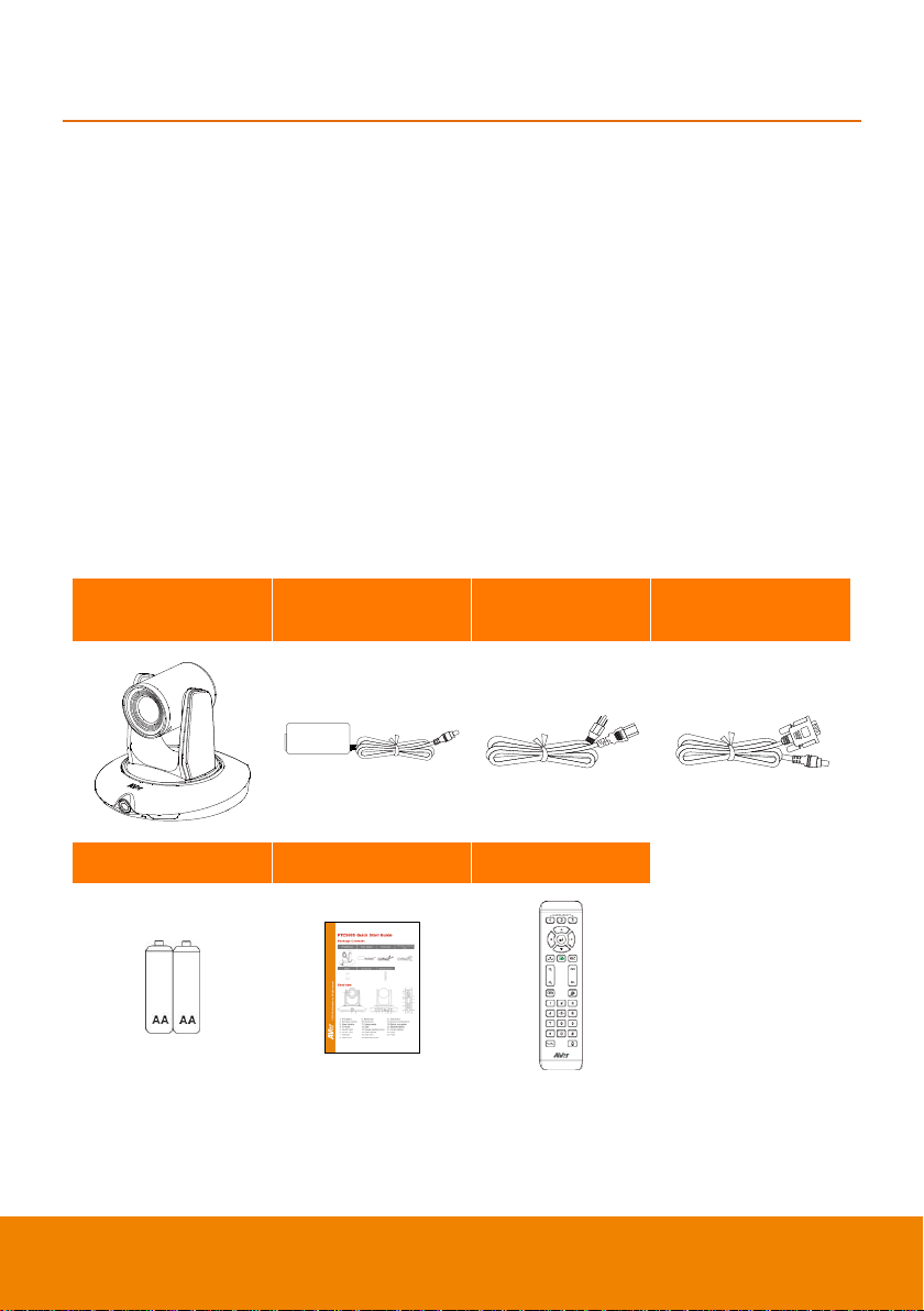
PTC500S unit
Power adapter
Power cord
RS-232 to D-Sub 9
cable
Battery
Quick Guide
Remote Control
AVer PTC500S is a professional tracking camera which can be wide area, stage or segment mode
depended on user’s subject target. The PTC500S use body motion and image analysis algorithm to
tracking target; the target subject no need to wear any signal transmit device. The PTC500S can
communicate with recording system through RS232, RS485 or network interface. The PTC500S has
stable system, easy to use, and suitable for classroom, meeting room, and any lecture or course
environment.
Package Contents
The following items are included in the package. Please check if each item is available and confirm if
there are damage before using.
[Note]
1. Do not disassemble or modify the items by yourself. Contact the dealer for help when the items is
failed to work.
2. Store the items in a dry place away from moisture.
[Note] The power cord will vary depending on the standard power outlet of the country where it is sold.
1
Page 8
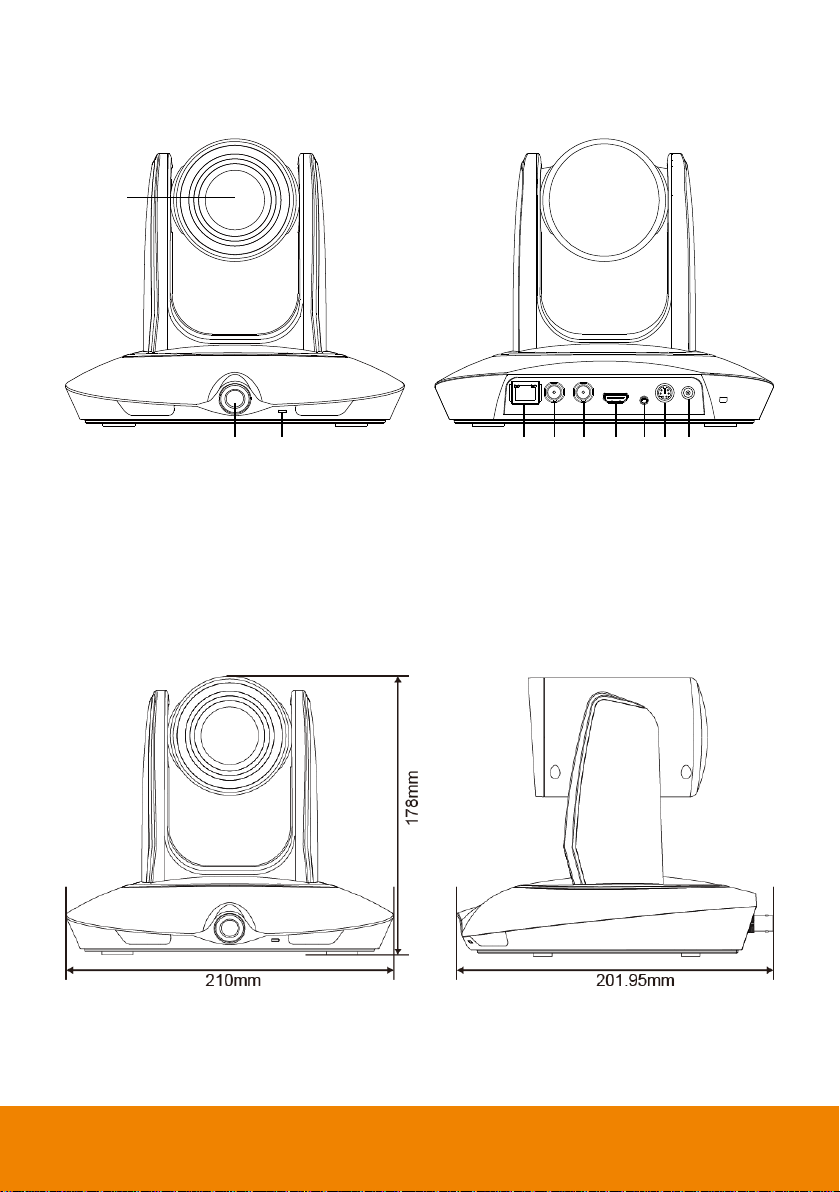
1
2 3 4 5 6 7 8 9 10
1. PTZ camera
6. 3G-SDI 1 port(PTZ view)
2. Panoramic camera
7. HDMI port(PTZ view)
3. Power indicator
8. Video in port
4. RJ-45 port
9. RS-232 port
5. 3G-SDI 2 port(Panoramic view)
10. Power jack
Product Overview
Dimension
2
Page 9
1
6
8
10
13
2
3
4
7
9
11
12
5
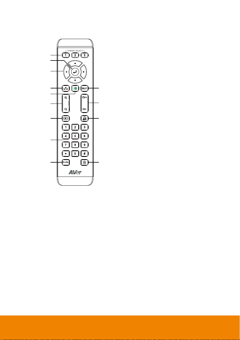
1. Camera select
[Note] Only channel No.1 is available.
Before you use remote, please press
channel 1 first.
2. Enter
3. Camera direction control
4. White balance
5. OSD menu
6. Back light control
7. Zoom in/out
8. Exposure compensation
9. Back to zero position((home preset)
[Note] Press and hold 3 seconds to turn
on or turn off the PTC500S unit.
Only support at PTC500S FW version
0.0.1000.08 and above.
10. Tracking on/off
11. Number buttons
12. Profile
13. Preset
Remote Controller
3
Page 10
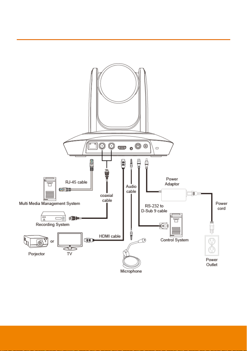
CONNECTIONS
Device Connections
4
Page 11
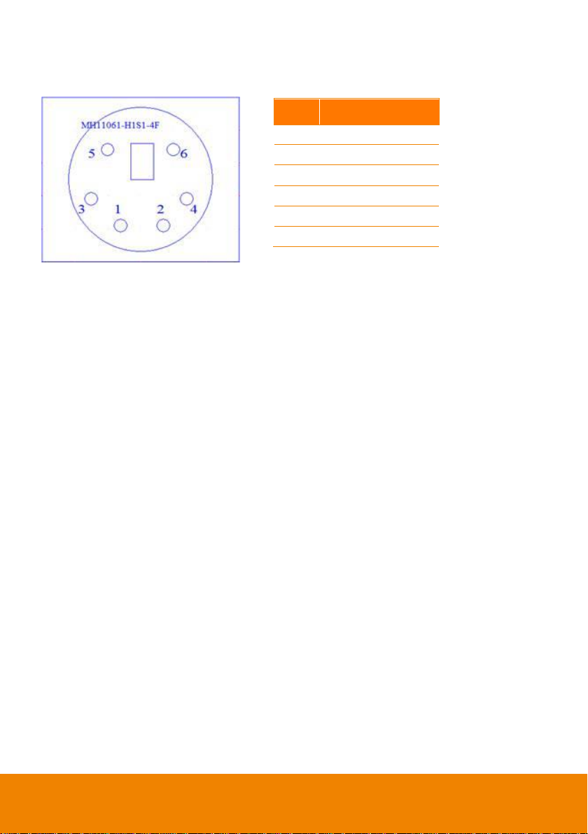
Pin
Definition
1
RS232_DTR
2
RS232_DSR
3
N.C. 4 RS232_TXD
5
GND
6
RS232_RXD
RS232 Pin Definition
5
Page 12
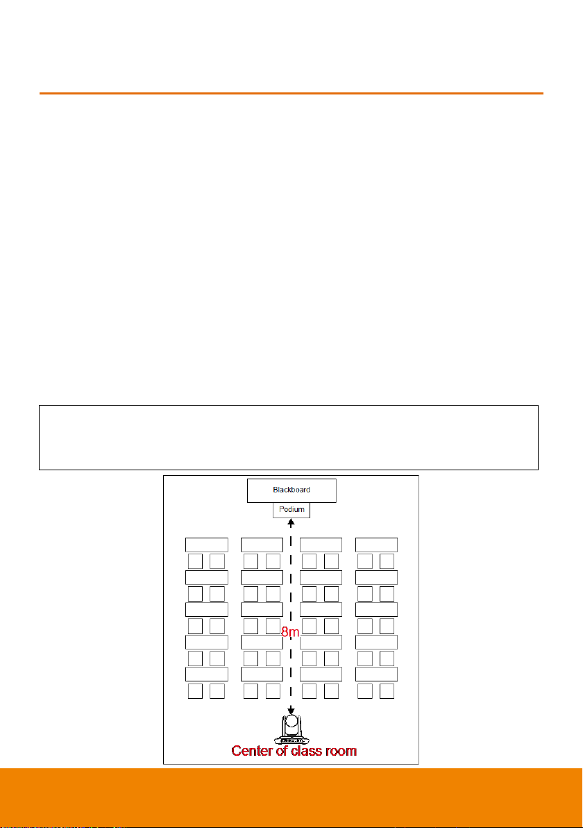
Install height range (from floor): 2 ~ 3m; 2.4m is suggested.
Distance range to podium: 4~15m; 8m is suggested.
Position: Center of class room.
MODE INTRODUCTION
Wide Area Mode
Application
This mode is suitable for teacher or lecturer tracking in normal classroom. The algorithm is
based on face detection.
Regardless of the target close to or away from PTC500S, the tracking camera will automatically
zoom in/out to maintain the appropriate size and proportion.
If the tracking target is locked, PTC500S will not be affected by the other moving objects.
Limitation
This mode is easily affected by the brown objects or the color similar to skin. Things like cartons
and wood furniture.
It should be used in bright environment. If the light is not enough, it will cause PTC500S unable
to distinguish the target face and lead to the tracking failure.
It could not be used on the environment with high bright contrast. For example, the
environment is with IFP or projectors. When the target enters or leaves the high bright contrast
zone, it is risky for PTC500S to lose the tracking target.
6
Page 13
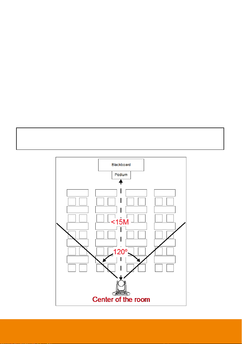
Install height range (from floor): 2 ~ 3m; 2.4m is suggested.
Position: Center of the room.
Stage and Segment Mode
Application
It’s suitable for complicate environment. It’s the remedy for teacher mode. Due to absolute
motion tracking, PTC500S will not be affected by the color of wood furniture or the high bright
contrast.
Suitable for only one person in the tracking zone.
Limitation
Tracking is only available for horizontal movement. It will not auto zoom in/out for target close to
or leaving away from PTC500S
Due to absolute motion checking, it is unable to check who the target is or who the interference
is. It doesn’t have anti-interference ability.
Due to the FOV limit, the tracking zone is only available within 120 degrees.
Distance limitation <15M
7
Page 14
WEB SETUP
Make a Connection to PTC500S via Browser
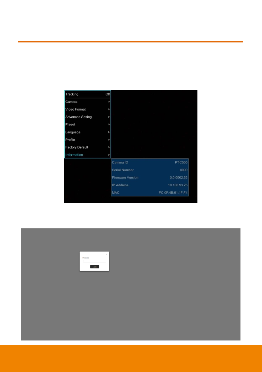
1. Find the IP address of PTC500S: call out OSD menu of PTC500S. Use ▲ and ▼ buttons on
remote controller to go to “Information” to find the IP address information.
2. Open the browser on your PC and enter the IP address of PTC500S.
3. Enter the password of PTC500S to login. The default password is “admin”.
8
Page 15
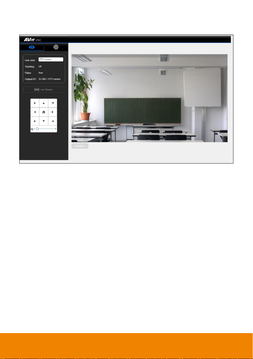
4. After login, User should see the main interface of PTC500S.
9
Page 16
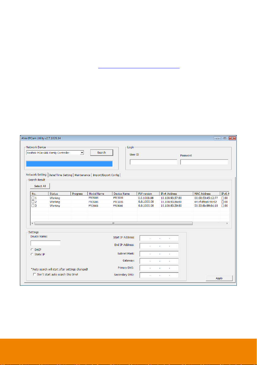
Make a Connection to PTC500S via AVer IPCam Utility
[Note] The PTC500S FW version 0.0.1000.08 and above supports IPCam Utiltiy application.
To find the IP address of your cameras, you can execute the IPCam Utility installer. Follow the below
steps to find the IP address of camera.
1. Download the IPCam Utility from http://www.aver.com/download-center .
2. Run the IPCam Utility.
3. Click Search, and all available devices will be listed on the screen.
4. Select a camera from the list.
5. The corresponding fields of IP address will display.
6. Double-click on the IP address of camera from the list can connect to camera through the browser.
[Note] If IPCam utility cannot find the camera, please check following:
1. Please make sure the Ethernet connection of camera is well connected.
2. The camera and PC (IPCam utility) are in the same LAN segment.
10
Page 17
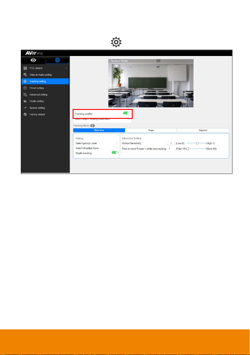
Enable Tracking Function
Turn on and off the tracking function. Select > Tracking setting > Tracking on.
11
Page 18
144
144
1080
1920
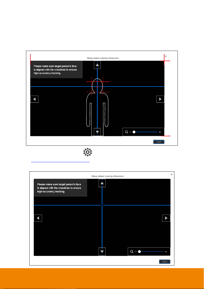
Setup Object Viewing Dimension
Set the size of tracking object on the screen. Aim the intersection of blue line can get best curacy of
tracking. The illustration shows the minimum request. Set the person proportion more than the
illustration. If target proportion is smaller than the photo, it may cause the tracking failure.
To set the object size for tracking select > Tracking setting > Setup object viewing dimension
(Also see Object Viewing Dimension Setting chapter).
Use ▲, ▼, , and zoom in/out to adjust object size. Then, click “Save” to save the setting.
12
Page 19
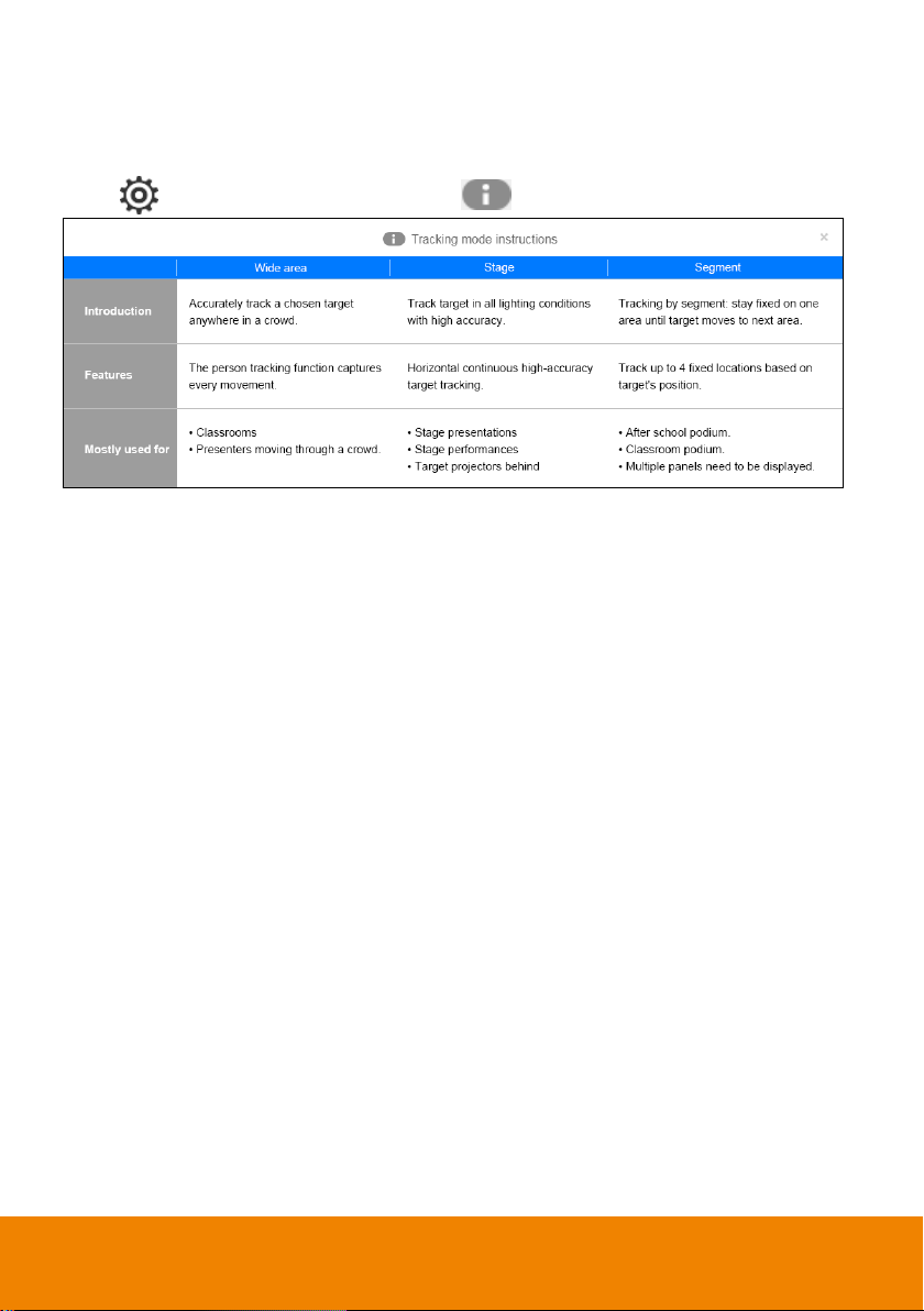
Tracking Mode Instruction
View the each tracking mode’s brief instruction, feature, and use environment.
Select > Tracking Setting > Tracking Mode
to view tracking mode instruction.
13
Page 20
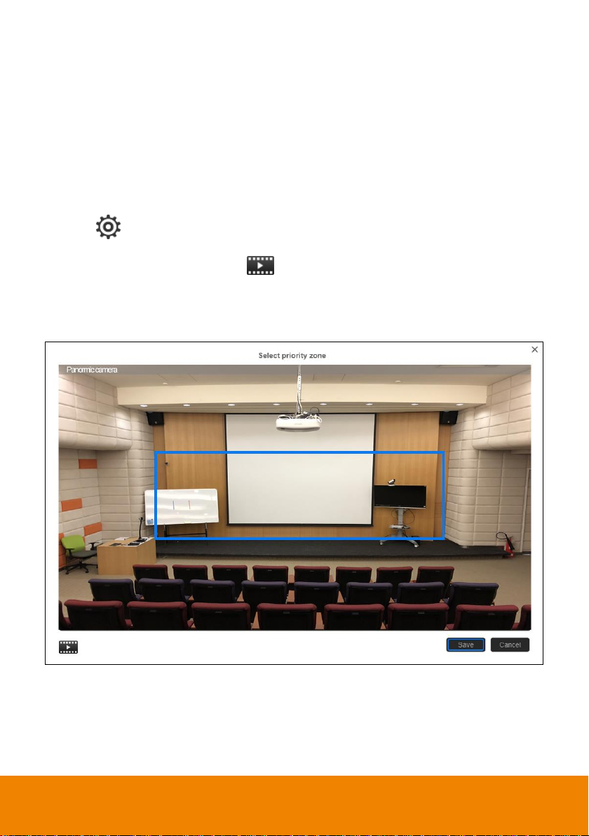
Wide Area Mode
The PTC500s will start tracking when object enter the priority zone and the face of object is
detected.
Setup Priority Zone
If PTC500S detects motions in the defined zone and PTC500S will be triggered to track. If priority zone
doesn’t setup, then, all the panoramic view will be the default active zone.
[Note] The screen of priority zone setting is based on panoramic camera view.
1. Select > Tracking setting > Wide Area > Select priority zone.
2. An online tutorial will display. User can watch to learn how to setup tracking zone. Click Skip to
stop tutorial. To watch again, select
3. In Select priority zone screen, drag and select the area that wants to be tracking (a blue frame will
show on screen). To re-select the area, just drag and select another wanted area.
4. Click “Save” to save the setting.
to play online tutorial.
14
Page 21
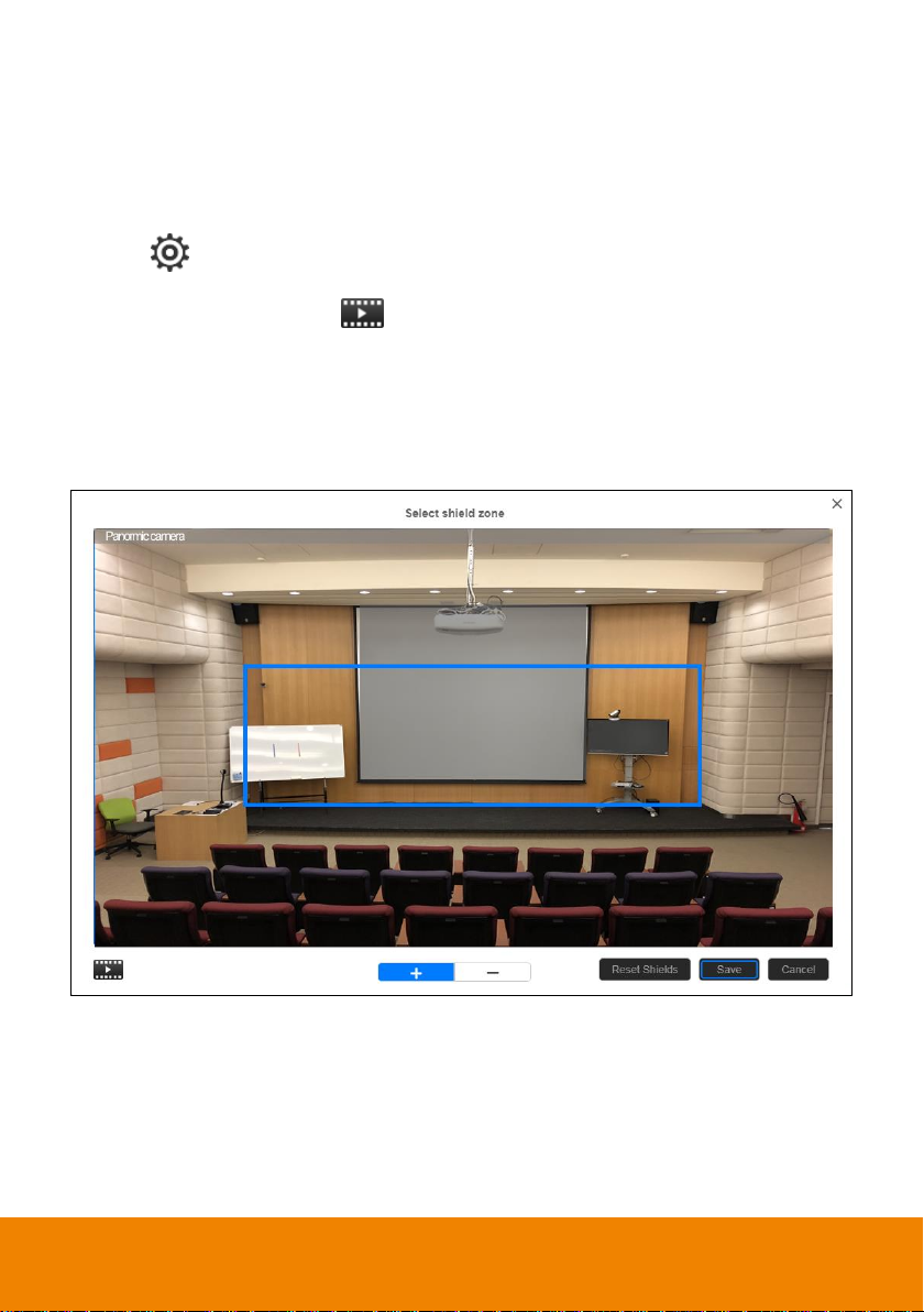
Setup Shielded Zone
Define the area that user doesn’t want camera to track. The shield zone should be within the active
zone. 8 shield zones can be set.
[Note] The screen of shielded zone setting is based on panoramic camera view.
1. Select > Tracking setting > Wide Area > Select shielded zone.
2. An online tutorial will display. User can watch to learn how to setup shield zone. Click Skip to stop
tutorial. To watch again, select
3. In Shielded tracking zone screen, click the “+” and select the area in tracking zone that don’t want
to be tracking (a gray block will show on screen). For example: Shielded the projector screen and
TV that may influence the tracking. To delete the shield zone area, click “-“and select the shield to
delete it. Or select “Reset Shields” to delete all shields.
4. Select “Save” to save the setting.
to play online tutorial.
15
Page 22
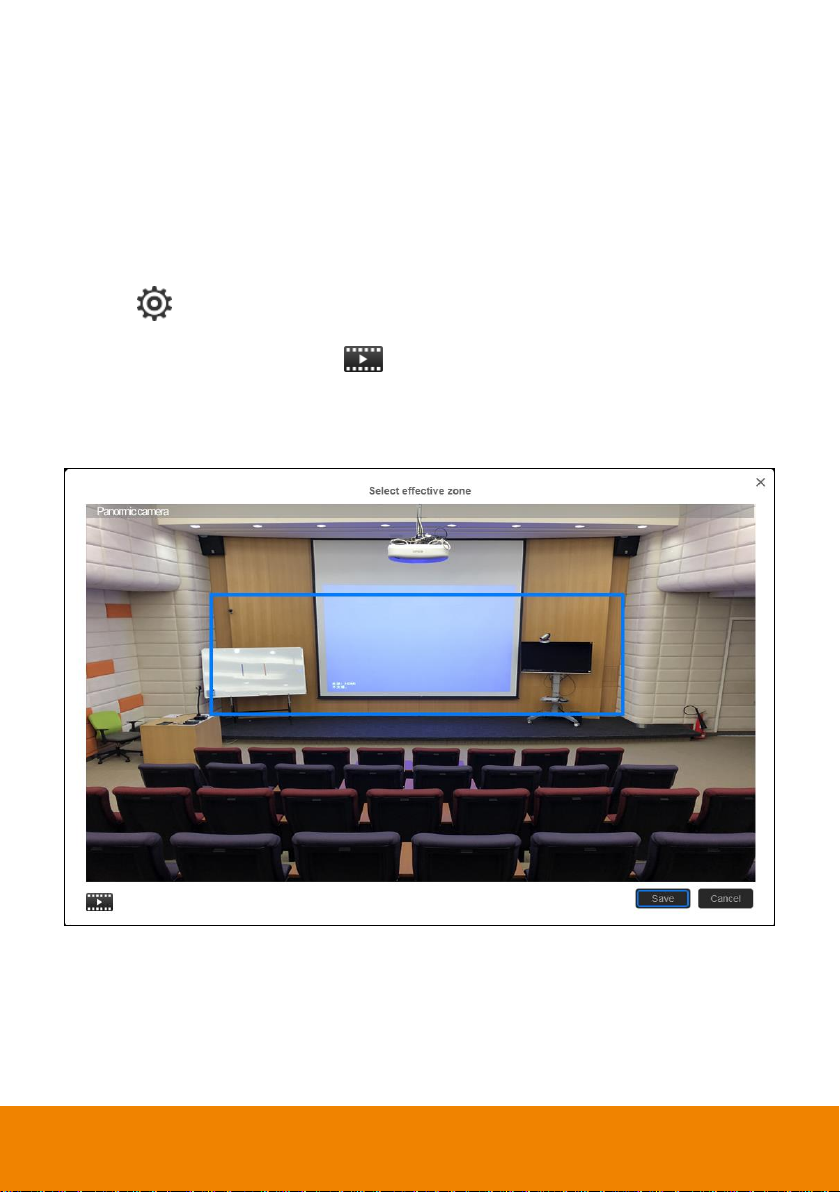
Stage Mode
The PTC500S will start tracking when there is an object moving in effective zone.
Setup Effective Zone
If PTC500S detects motions in the defined zone and PTC500S will be triggered to track. If tracking
zone doesn’t setup, then, all the panoramic view will be the default active zone.
[Note] The screen of effective zone setting is based on panoramic camera view.
1. Select > Tracking > Stage > Select effective zone.
2. An online tutorial will display. User can watch to learn how to setup tracking zone. Click Skip to
stop tutorial. To watch again, select
3. In Select effective zone screen, drag and select the area that wants to be tracking (a blue frame will
show on screen). To re-select the area, just drag and select another wanted area.
4. Click “Save” to save the setting.
to play online tutorial.
16
Page 23
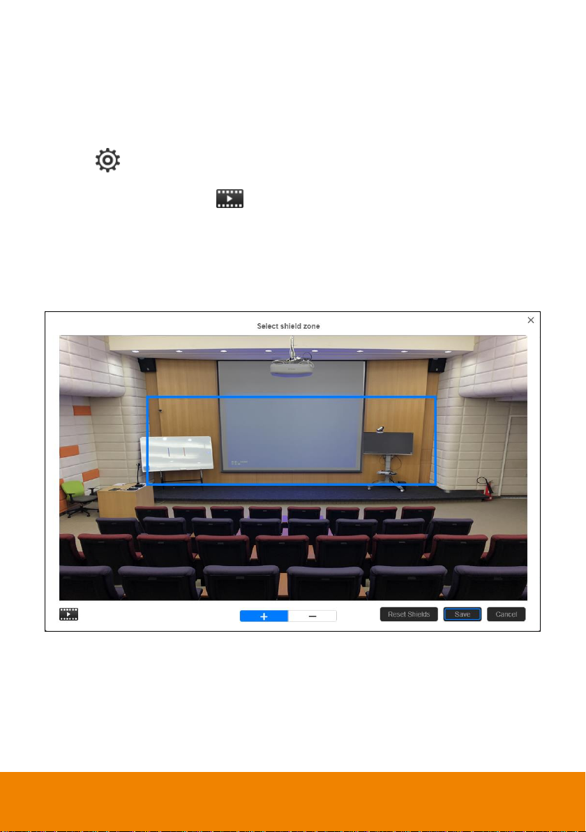
Setup Shielded Zone
Define the area that user doesn’t want camera to track. The shield zone should be within the active
zone. 8 shield zones can be set.
[Note] The screen of shield zone setting is based on panoramic camera view.
1. Select > Tracking setting > Stage > Select shielded zone.
2. An online tutorial will display. User can watch to learn how to setup shield zone. Click Skip to stop
tutorial. To watch again, select
3. In Shielded tracking zone screen, click the “+” and select the area in tracking zone that don’t want
to be tracking (a gray block will show on screen). For example: Shielded the projector screen and
TV that may influence the tracking. To delete the shield zone area, click “-“and select the shield to
delete it. Or select “Reset Shields” to delete all shields.
4. Select “Save” to save the setting.
to play online tutorial.
17
Page 24
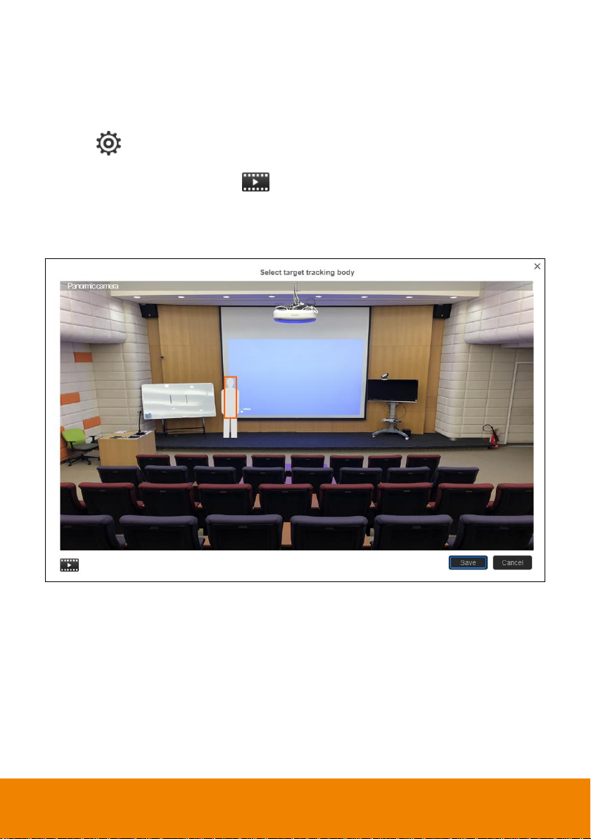
Setup Target Tracking Body
Define the width of tracking target. 1 target zone can be set.
[Note] The screen of target tracking body is based on panoramic camera view.
1. Select > Tracking setting > Stage > Select target tracking body.
2. An online tutorial will display. User can watch to learn how to setup tracking zone. Click Skip to
stop tutorial. To watch again, select
3. In select target tracking body screen, drag and set the width of object that wants to be tracked (an
orange frame will show on screen). To re-set the width of object, just drag again.
4. Click “Save” to save the setting.
to play online tutorial.
18
Page 25
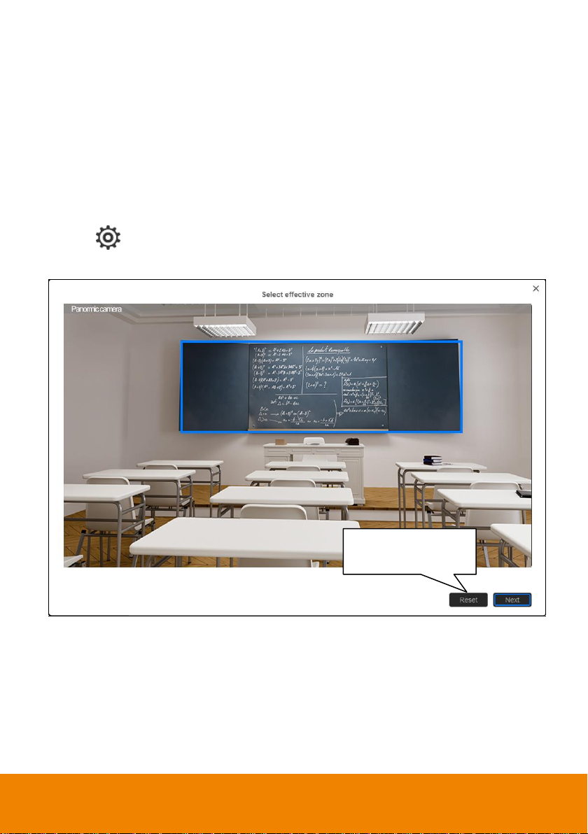
Click it to reset the
selected tracking area.
Segment Mode
The PTC500S will start tracking when object is moving between the blocks.
Setup Effective Zone
If PTC500S detects motions in the defined zone and PTC500S will be triggered to track. If effective
zone doesn’t setup, then, all the panoramic view will be the default active zone. The effective zone can
be defined from 2 to 4 blocks.
[Note] The screen of effective zone setting is based on panoramic camera view.
1. Select > Tracking setting > Segment > Select effective zone.
2. Drag a tracking area on screen (blue frame). Then, click “Next” button.
19
Page 26
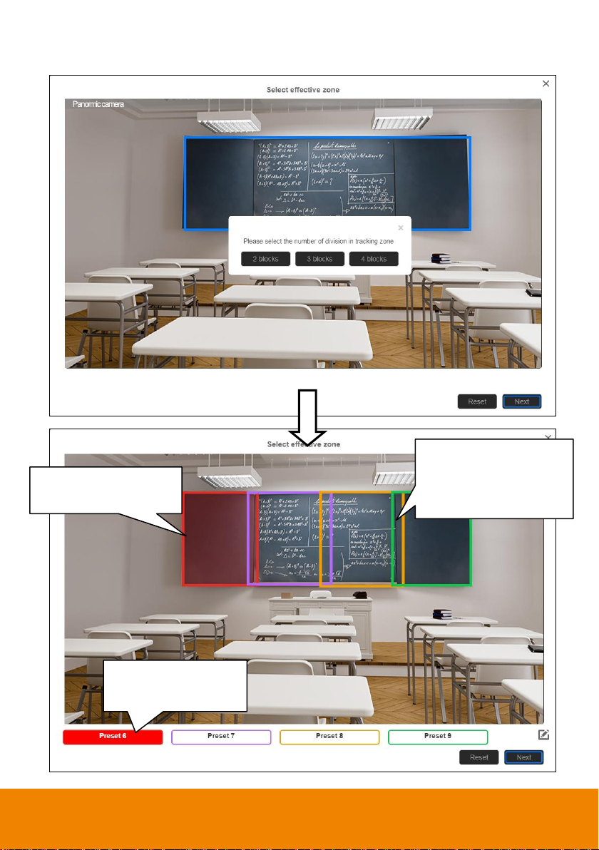
Click on the edge (left &
right) to adjust block size.
Click the preset button to
adjust block size.
Make an overlap area
between blocks to avoid the
camera move frequently at
junction point.
3. Select the tracking zone blocks – 2, 3, or 4 blocks. At least 2 blocks must be set.
20
Page 27
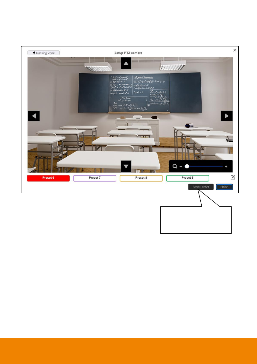
When each time preset
position is set, click “Save” to
save the settings.
4. Click “Next” to set the position of tracking zone. Click preset button and use
to adjust to the desire position. When each time preset position is set, click “Save” to save the
settings.
▲,▼,
,
, Zoom +/-
5. Click “Finish” to complete the settings.
21
Page 28
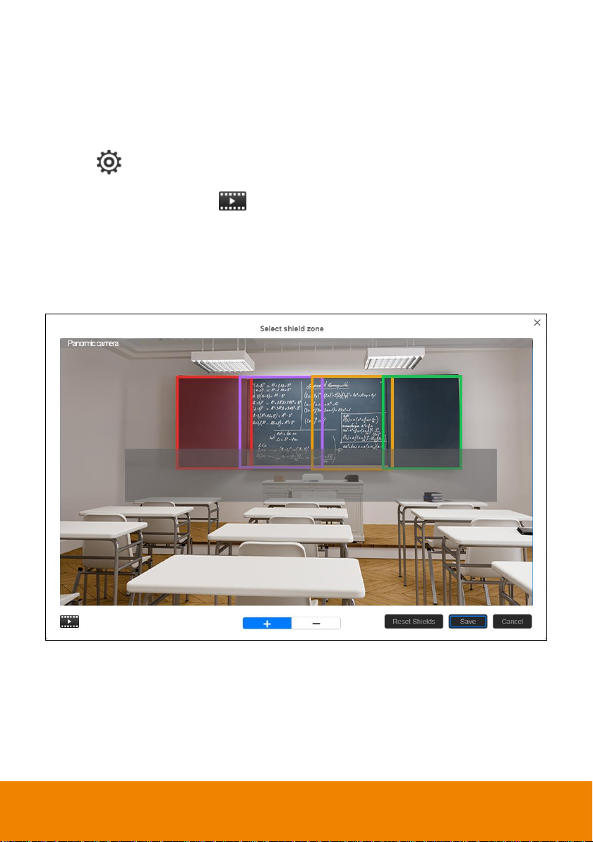
Setup Shielded Zone
Define the area that user doesn’t want camera to track. The shield zone should be within the active
zone. 8 shield zones can be set.
[Note] The screen of shield zone setting is based on panoramic camera view.
1. Select > Tracking setting > Segment > Select shielded zone.
2. An online tutorial will display. User can watch to learn how to setup shield zone. Click Skip to stop
tutorial. To watch again, select
3. In Shielded tracking zone screen, click the “+” and select the area in tracking zone that don’t want
to be tracking (a gray block will show on screen). For example: Shielded first row of student that
may influence the tracking. To delete the shield zone area, click “-“ and select the shield to delete it.
Or select “Reset Shields” to delete all shields.
4. Select “Save” to save the setting.
to play online tutorial.
22
Page 29
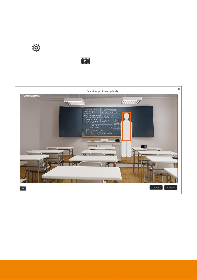
Setup Target Tracking Body
Define the width of tracking target. 1 target zone can be set.
[Note] The screen of target tracking body is based on panoramic camera view.
1. Select > Tracking setting > Segment > Select target tracking body.
2. An online tutorial will display. User can watch to learn how to setup tracking zone. Click Skip to
stop tutorial. To watch again, select
3. In select target tracking body screen, drag and set the width of object that wants to be tracked (an
orange frame will show on screen). To re-set the width of object, just drag again.
4. Click “Save” to save the setting.
to play online tutorial.
23
Page 30
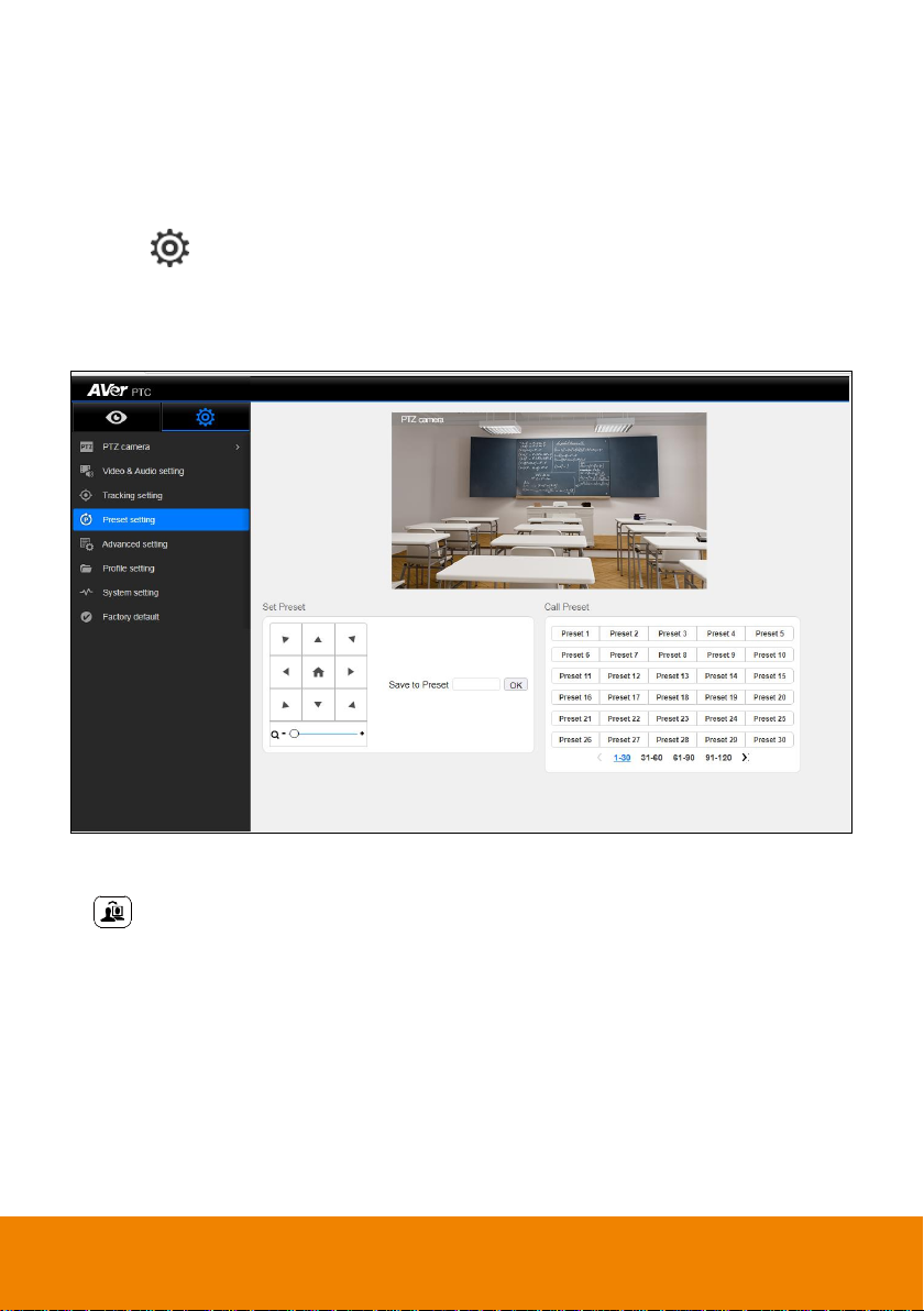
Preset Setup
Define the specific location to view when select preset number (1~255). When PTC500s lose tracking,
it will back to the preset 1 position.
1. Open the browser and enter the IP address of PTC500S to login to PTC500S.
2. Select > Preset Setting.
3. Use the direction control panel to adjust the PTC500S to desires position.
4. Next, select the preset number in “Save to Preset” column and click “Save” button to save the
preset.
5. Select preset number in Call Preset section can view preset position view.
6. After call preset, the tracking will be off. Remember to turn on the tracking manually. Or press
on remote controller.
24
Page 31
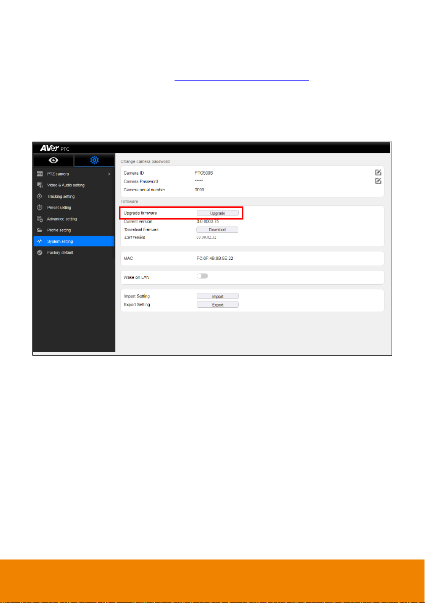
Firmware Update
1. Download the newest firmware from http://www.aver.com/download-center .
2. Connect to camera through browser.
3. Select System > Firmware > Upgrade firmware > Upgrade.
4. Select the firmware and select “Upload” button.
5. After updating, refresh the browser.
Using RTSP connect to Camera
Use RSTP player connecting to camera; please enter the following RTSP URL in your application such
as VLC, PotPlayer, or QuickTime.
PTZ camera: rstp:// IP address of PTC500S:554/live_st1
For example: rstp://192.168.1.1:554/live_st1
Panoramic camera: rstp://IP address of PTC500S:8554/live_st2
For example: rstp://192.168.1.1:8554/live_st2
25
Page 32
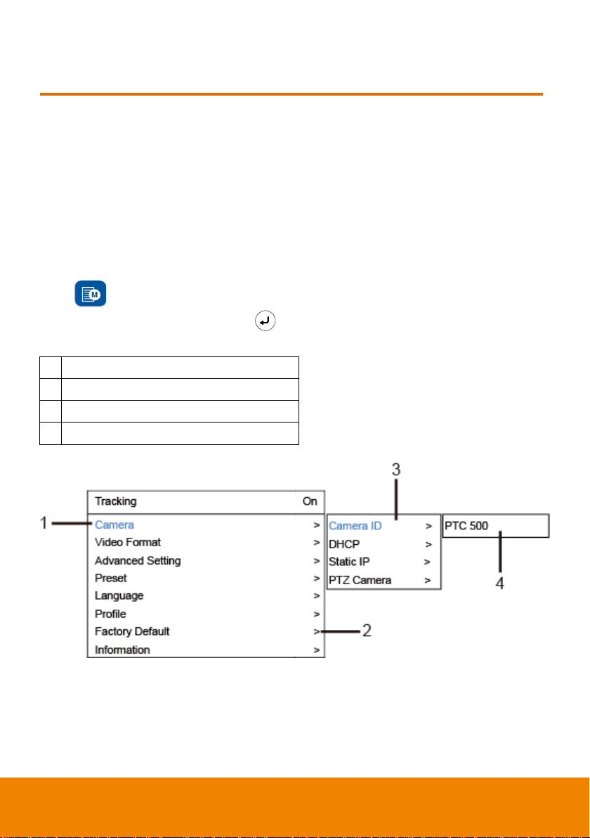
1
Blue text indicates the current selection.
2
“>” means has sub-menu or value selection.
3
Sub-menu
4
Column for enter value or value selections.
OSD SETUP
Before You Begin
Make sure all connections are connected successfully before using the PTC500S. Connections error
will cause no image showing or no reaction. (For more information, please refer to INSTALLATION
chapter.)
For the First Time Use
Trigger OSD Menu
Press button on remote controller to call out OSD menu. Use to enter sub-menu, use ▲
and ▼ to move to the selection and use to confirm the selection. Press button can back to
previous level of menu.
26
Page 33
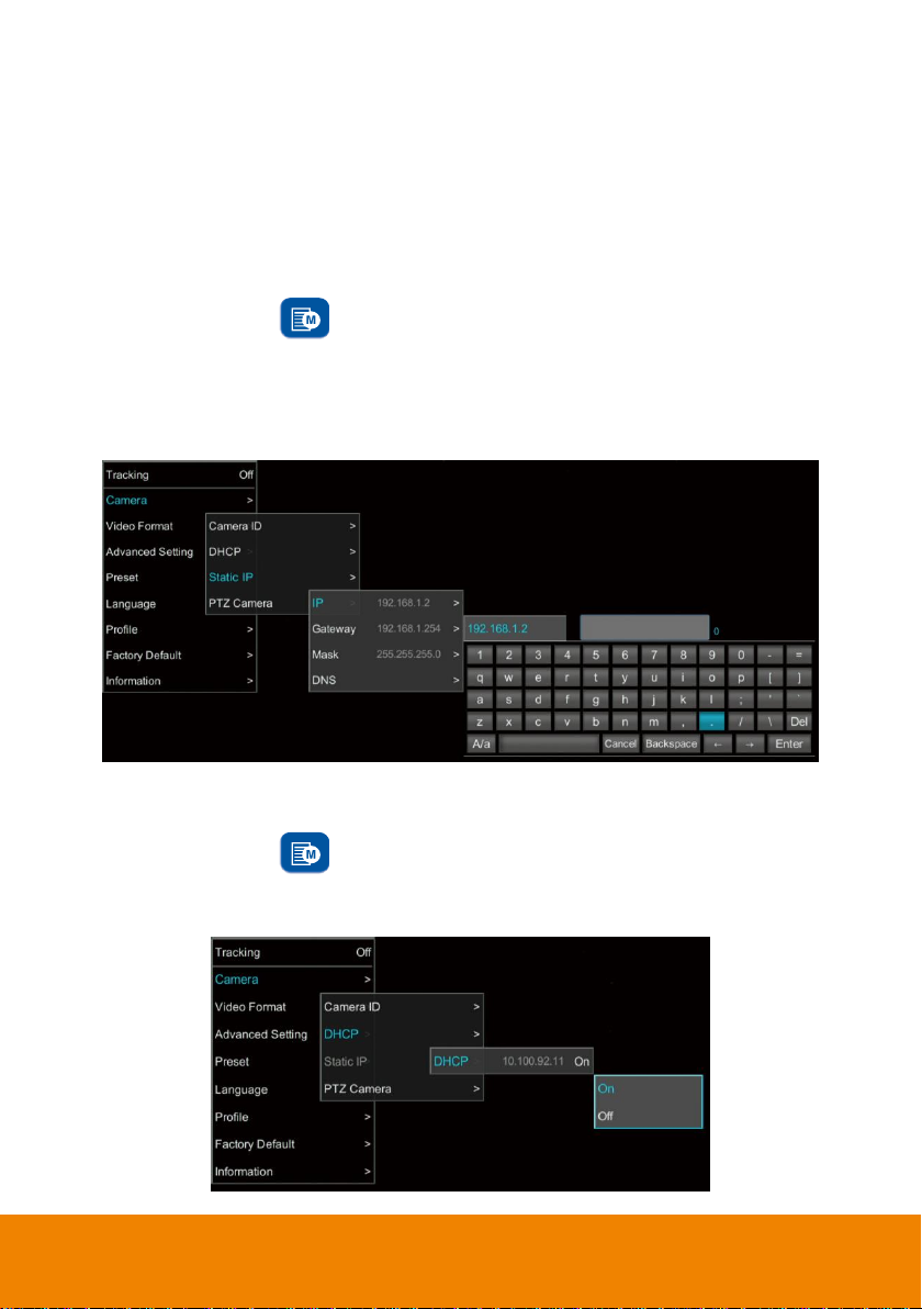
Setup IP Address
Setup IP address of PTC500S.
There are two ways to setup IP address of PTC500S. Please follow the steps below to setup the IP
address.
Static IP Address
Assign a fix IP address for PTC500S.
1. After starting-up, press button on remote control to call out OSD menu.
2. Turn the DHCP off first. Go to Camera > DHCP > DHCP > Off then press or enter button to
confirm the selection. The menu selection will switch to “Static IP” when DHCP off is applied.
3. Use ▲, ▼, Enter button, and on-screen keyboard to setup the “IP”, “ Gateway”, “Mask” and
“DNS”.
Dynamic IP Address(DHCP)
Get IP address from your local DHCP server.
1. After starting-up, press button on remote control to call out OSD menu.
2. Use ▲ and ▼ buttons to select the Camera > DHCP > DHCP > On, then press or enter button
to get IP address from local DHCP server.
27
Page 34
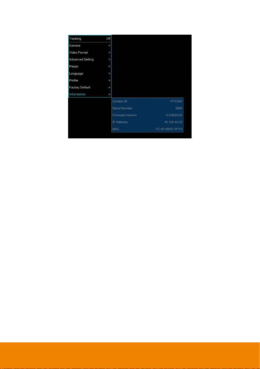
3. Use ▲ and ▼ buttons go to “Information” to check the IP address information.
28
Page 35

Tracking
On
Camera
Video Format
Preset
Advanced Setting
Language
Profile
Factory Default
Information
>
>
>
>
>
>
>
>
Tracking
On
Camera
Video Format
Advanced Setting
Preset
Language
Profile
Factory Default
Information
>
>
>
>
>
>
>
>
On
Off
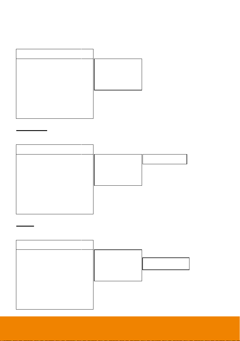
OSD Tree Map
Main
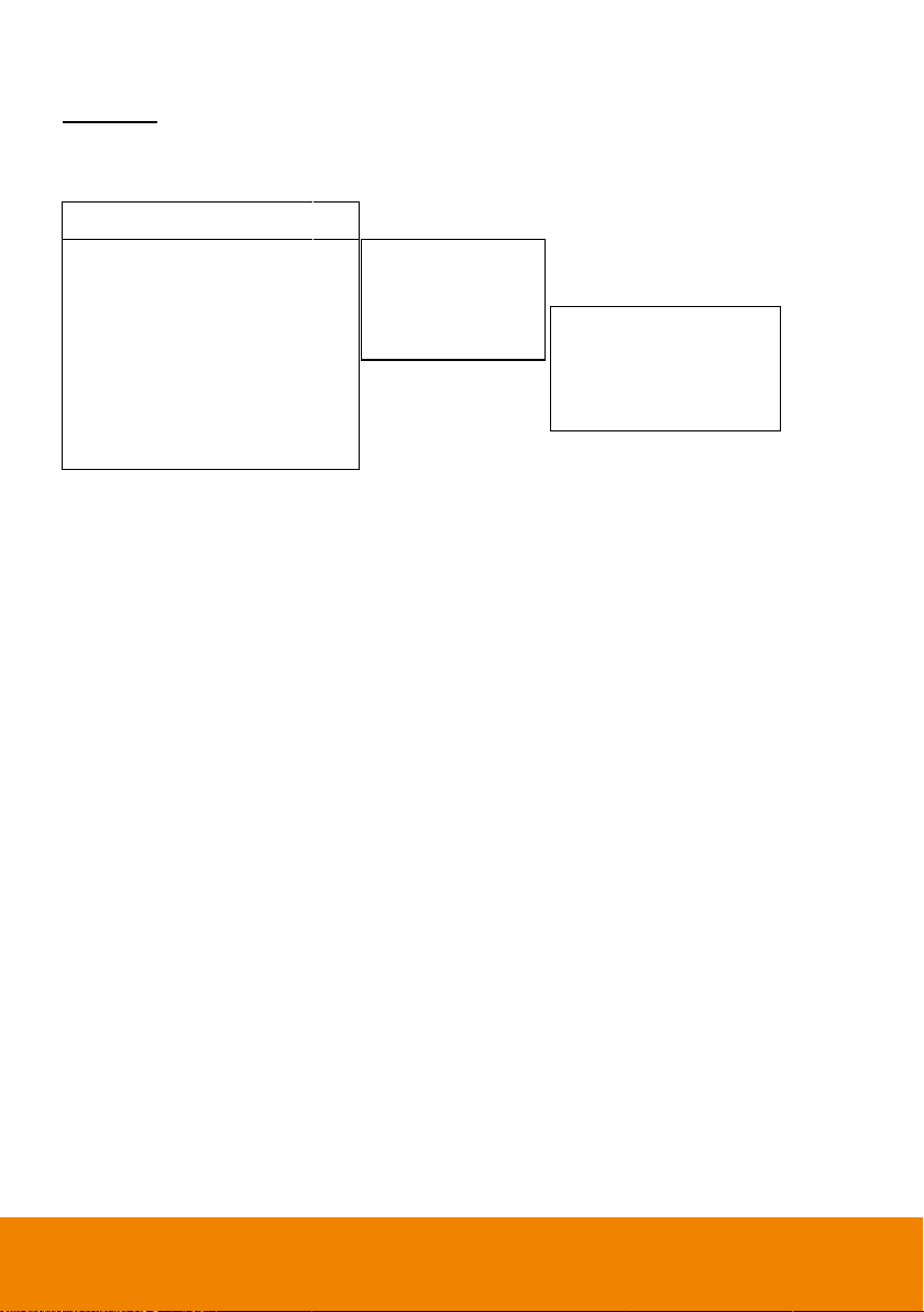
Tracking
User can enable or disable auto-tracking.
PTC500S will not track on object automatically when the feature is disabled.
To enable auto-tracking, please select “On”.
To disable auto-tracking, select “Off”.
29
Page 36
Tracking
On
Camera
Video Format
Advanced Setting
Preset
Language
Profile
Factory Default
Information
>
>
>
>
>
>
>
>
Tracking
On
Camera
Video Format
Advanced Setting
Preset
Language
Profile
Factory Default
Information
>
>
>
>
>
>
>
>
Tracking
On
Camera
Video Format
Advanced Setting
Preset
Language
Profile
Factory Default
Information
>
>
>
>
>
>
>
>
Camera ID >
DHCP >
Static IP >
PTZ Camera >
PTC500S
Camera ID >
DHCP >
Static IP >
PTZ Camera >
DHCP10.1.0.1 ON
Camera ID >
DHCP >
Static IP >
PTZ Camera >
Camera
In the section, users can change camera ID, network setting and adjust parameter of camera settings.
Camera ID
To change camera ID, please select Camera > Camera ID.
DHCP
To enable DHCP, select Camera > DHCP.
30
Page 37
Tracking
On
Camera
Video Format
Advanced Setting
Preset
Language
Profile
Factory Default
Information
>
>
>
>
>
>
>
>
Camera ID >
DHCP >
Static IP >
PTZ Camera >
IP 10.1.0.1
Mask 255.255.0.255
Gateway 10.1.0.1
DNS
>
>
>
>
Static IP
To setup network as a static IP, select Camera > Static IP (Please set DHCP off before the Static IP
setting)
31
Page 38

Tracking
On
Camera
Video Format
Advanced Setting
Preset
Language
Profile
Factory Default
Information
>
>
>
>
>
>
>
>
Camera Mode Full Auto
Full Auto
Shutter Priority
Iris Priority
Manual
White Balance
Shading Correction
>
>
>
>
>
>
>
Pan/Tile Speed
Zoom Speed
Digital Zoom Limit
PTZ Zoom Focus
Power Up
Frequency
Contrast
Saturation
Sharpness
NosieReduction
1
Low
12
Off
Home
Auto
2
5
Medium
Medium
Camera ID
DHCP
Static IP
PTZ Camera
>
>
>
>
PTZ Camera
To adjust the parameters of PTZ camera, select Camera >PTZ Camera.
32
Page 39

Camera Mode Full Auto
Full Auto
Shutter Priority
Iris Priority
Manual
White Balance
Shading Correction
>
>
>
>
>
>
>
Pan/Tile Speed
Zoom Speed
Digital Zoom Limit
PTZ Zoom Focus
Power Up
Frequency
Contrast
Saturation
Sharpness
NosieReduction
1
Low
12
Off
Home
Auto
2
5
Medium
Medium
Full Auto
Shutter Priority
Iris Priority
Manual
>
>
>
>
Slow Shutter
Maximum Gain
Back Light compens
Exposure
Off
24dB
Off
0
Speed
Maximum Gain
Exposure
1/30
24dB
0
Slow Shutter
Iris
Maximum Gain
Exposure
Off
F6.8
24dB
0
Maximum Gain
Speed
Iris
24dB
1/30
F6.8
Full Auto
Shutter Priority
Iris Priority
Manual
>
>
>
>
Full Auto
Shutter Priority
Iris Priority
Manual
>
>
>
>
Full Auto
Shutter Priority
Iris Priority
Manual
>
>
>
>
Camera Mode
There are 4 modes of camera mode, you can select one from Camera > PTZ Camera > Camera
Mode.
33
Page 40

White Balance
Camera Mode Full Auto
Full Auto
Shutter Priority
Iris Priority
Manual
White Balance
Shading Correction
>
>
>
>
>
>
>
Pan/Tile Speed
Zoom Speed
Digital Zoom Limit
PTZ Zoom Focus
Power Up
Frequency
Contrast
Saturation
Sharpness
NosieReduction
1
Low
12
Off
Home
Auto
2
5
Medium
Medium
Mode
Auto
Auto
One Push
Manual
6247
To adjust white balance value, select Camera > PTZ Camera > White Balance.
34
Page 41

Tracking
On
Camera
Video Format
Advanced Setting
Preset
Language
Profile
Factory Default
Information
>
>
>
>
>
>
>
>
Camera Mode Full Auto
Full Auto
Shutter Priority
Iris Priority
Manual
White Balance
Shading Correction
>
>
>
>
>
>
>
Pan/Tile Speed
Zoom Speed
Digital Zoom Limit
PTZ Zoom Focus
Power Up
Frequency
Contrast
Saturation
Sharpness
NosieReduction
1
Low
12
Off
Home
Auto
2
5
Medium
Medium
Upper Left
Upper Right
Bottom Left
Bottom Right
Off
Off
Off
Off
3G-SDI1/HDMI
3G-SDI2
PIP
Auto
Auto
0
Shading Correction
To adjust shading correction, select Camera > PTZ Camera > Shading Correction (The option is for
the screen corner shadow fixing.)
Video Format
To adjust Video Format, select Video Format from OSD menu.
35
Page 42
Tracking
On
Camera
Video Format
Advanced Setting
Preset
Language
Profile
Factory Default
Information
>
>
>
>
>
>
>
>
3G-SDI1/HDMI
3G-SDI2
PIP
Auto
Auto
0
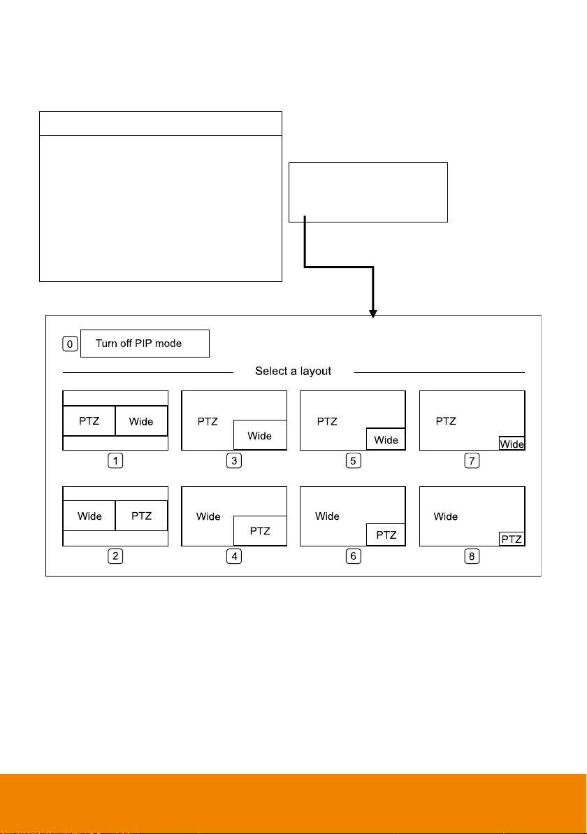
PIP Mode
Select picture-in-picture(PIP) mode. To turn off the PIP mode, select mode 0.
36
Page 43
Tracking
On
Camera
Video Format
Advanced Setting
Preset
Language
Profile
Factory Default
Information
>
>
>
>
>
>
>
>
Tracking
On
Camera
Video Format
Advanced Setting
Preset
Language
Profile
Factory Default
Information
>
>
>
>
>
>
>
>
RS232 Protocol
Address(ADDRD)
Baud Rate
VISCA-over-IP
VISCA
1
9600
off
Set
Call 1 1
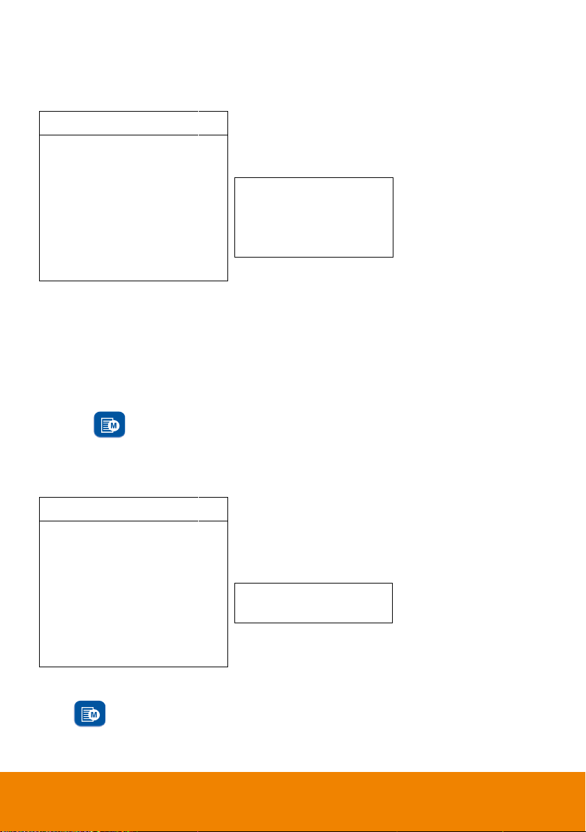
Advanced Setting
To adjust RS232 protocol, address and baud rate, select Advance Setting from OSD menu.
Preset
PTC500S allows you to set 10 preset locations via remote controller.
To set up preset point:
1. Enter OSD and turn off the tracking function.
2. Move camera to the prefer location and zoom distance.
3. Press bottom > Preset > Set and use arrow key to assign a preset number and press enter
button on remote controller.
[Tip] Shortcut of setting a preset location as following:
Press “P” button > press “↑” > press number you want to set, ex: 1 and press enter.
To call a preset location:
Press bottom > Preset > call and use arrow key to select which preset number you would like
to recall -> press enter button on remote controller.
[Tip] Shortcut of calling a preset location: press “P” > press number you want to recall, ex: 1.
37
Page 44

Tracking
On
Camera
Video Format
Advanced Setting
Preset
Language
Profile
Factory Default
Information
>
>
>
>
>
>
>
>
Tracking
On
Camera
Video Format
Advanced Setting
Preset
Language
Profile
Factory Default
Information
>
>
>
>
>
>
>
>
English
繁體中文
簡体中文
日本語
Deutsch
Francais
Espanol
한국어
Vietnamese
Set
Apply
default
default
Language
To change language, go to OSD menu > Language.
Profile
PTC500S allows you to save 5 profiles.
To set the profile, go to OSD menu > Set and use arrow key to assign a number and press enter button.
To call the profile, go to OSD menu > Apply and use arrow key to call an assigned number and press
enter button.
38
Page 45

Tracking
On
Camera
Video Format
Advanced Setting
Preset
Language
Profile
Factory Default
Information
>
>
>
>
>
>
>
>
Tracking
On
Camera
Video Format
Advanced Setting
Preset
Language
Profile
Factory Default
Information
>
>
>
>
>
>
>
>
Yes
No
Camera ID
Serial Number
Firmware Version
IP Address
MAC
PTC500
0000
0.0.0002.12
10.1.0.1
FB:5F:4B:61:1F:4F
Factory Default
To reset the PTC500S to default setting, go to OSD menu > Factory Default > Yes and press enter
button.
Information
To check out information on the PTC500S, ex: FW version. Go to OSD menu > Information.
39
Page 46

Button
Action
Function
Press and hold(3secs)
Power on/off camera.
[Note] Only support at PTC500S FW version
0.0.1000.08 and above.
3
Press three times(333)
Enable/Disable tracking function
When the hot key takes effect, you will see “tracking
on” or “tracking off” on the right bottom side.
6
Press six times(666666)
Enable/Disable AVer Logo
When the hot key takes effect, you will see “AVer”
logo on the right bottom side.
7
Press seven times(7777777)
Show the tracking indicator
When the hot key takes effect, you will see the
tracking indicator on the target face.
8
Press eight times(88888888)
Set PTC500S IP address as default
IP(192.168.1.168.)
9
Press nine times(999999999)
Password Reset mechanism:
When the hot key takes effect, the password of
entering Web UI will go back the default “admin”.
Hot Key
Press certain button on remote controller to perform hot key function.
40
Page 47

FAQ
1. How to define the zoom level of tracking target?
It’s determined by Setup Object Viewing Dimension. You should stand on the assigned location as a
proportional scale and zoom in/out to the proportion that you want. The following tracking will based on
this proportion.
2. How preset 1 has influence in the tracking settings?
When tracking cam loses the target, the position camera will go back to.
3. How does tracking work in Wide Area mode?
When object enter the priority zone, PTZ camera will move to the position of object and do the face
detection. After face is detected, PTZ camera will start tracking object in all area.
4. How does tracking work in Segment mode?
The tracking operation only works inside effective zone. When object is outside of effective zone, the
camera will stop tracking object.
5. How to avoid it start tracking other person in the same area?
It’s hard to do it. The algorithm is based on what the camera see. It is not intelligent enough to judge
who should track or not if 2 or more persons are in the active zone. It will randomly choose one to track.
6. Will tracking be lost when we use PTC500S in a situation which the projector is turned on?
Yes, it might happen in “Wide Area mode”. But we suggest to use “Stage mode” when the projector is
turned on. Stage mode can be used for any lighting conditions.
7. What is the definition of HOME position?
Home is the default position after camera booting. User can define position after camera booting in
below WebUI PTZPTZpower up ACT.
8. What about Preset 2 ~9 are used for anything related to tracking?
If you turn off tracking, PTC500S is a regular PTZ. User can manipulate it to assign position via center
control system command. The other presets are these usages.
9. This camera supports several profiles; does each profile have a different PRESET1?
Each profile has its own preset definition.
10. If we want to stop tracking and will to focus on specific location, how should I do?
Press "P" and the preset number. The camera will go to the assigned location.
11. In Wide area mode, I already masked the areas that might have something like president
photo or something similar to human, but why the camera is still attracted to these areas.
The shielding zone is only for motion shielding. In complicate environment, we suggest to use stage
mode to overcome it.
41
 Loading...