

Page 1

NXU Lite
User’s Manual
Ver.1.1.0.2
Page 2

OS
Function
Windows XP
Windows 7
Setup Wizard
N/A
Yes
Schedule by date
Yes
Yes
IPCam PnP
Yes
Yes
Manual Updates
Following are listed the new functions for the version 7.9.1.0033a and above of NXU surveillance
software.
[Note] User can press F1 to check NVR firmware version.
New Functions
Setup Wizard: A system setup wizard that will guide the user to setup the DVR system step
by step.
Schedule by date: Allows user to setup recording schedule by date.
IPCam PnP: Allows user to connect AVer IP camera series without any configuration; just plug
and play.
Active IP: Allows user to configure AVer IP camera series on DVR system; the IP camera
patch must be v. 7.0.0.118 or above.
ONVIF PTZ: NVR system supports IP PTZ function on the IP camera that is connected
through ONVIF protocol. The IP camera patch version must be v. 7.0.0.123 or above.
Function and OS supported table
i
Page 3

Important Notice
1. On Windows XP platform, the each partition capability limit is 2TB.
2. We do not recommend using KVM device with NXU system; KVM device may cause some
unexpected problem to effect NXU system operation.
ii
Page 4

Caution symbol is intended to alert the user of the important installation and operating
instructions. Fail to comply may damage the system.
i
Information symbol is intended to provide additional information for the purpose of
clarification.
- INFORMATION IN THIS DOCUMENT IS SUBJECT TO CHANGE WITHOUT
NOTIEC.
- THE INFORMATION CONTAINED HEREIN IS TO BE CONSIDERED FOR
REFERENCT ONLY.
Manual Conventions
The following conventions are used throughout this manual.
NOTICE
iii
Page 5

COPYRIGHT
© 2013 AVer Information Inc. All rights reserved.
All rights of this object belong to AVer Information Inc. Reproduced or transmitted in any form or by any
means without the prior written permission of AVer Information Inc. is prohibited. All information or
specifications are subject to change without prior notice.
DISCLAIMER
No warranty or representation, either expressed or implied, is made with respect to the
contents of this documentation, its quality, performance, merchantability, or fitness for a
particular purpose. Information presented in this documentation has been carefully
checked for reliability; however, no responsibility is assumed for inaccuracies. The
information contained in this documentation is subject to change without notice.
In no event will AVer Infomration Inc. be liable for direct, indirect, special, incidental, or
consequential damages arising out of the use or inability to use this product or
documentation, even if advised of the possibility of such damages.
TRADEMARKS
“AVer” is a trad em ark owned by AVer Info rmati on In c. Other tr ademark s used here in for
description purpose only belong to each of their companies.
iv
Page 6

TABLE OF CONTENTS
MANUAL UPDATES ................................................................................................... I
IMPORTANT NOTICE ................................................................................................ II
MANUAL CONVENTIONS ......................................................................................... III
CHAPTER 1 INTRODUCTION ............................................................................. 1
1.1 MINIMUM COMPUTER SYSTEM REQUIREMENTS .............................................. 1
1.2 DUAL MONITORS SETUP ............................................................................... 3
1.2.1 Graphic card with ATi chipset .......................................................................... 3
1.2.2 Graphic card with NVIDIA chipset ................................................................... 6
1.3 SOFTWARE INSTALLATION ............................................................................. 7
1.4 RUNNING THE NVR SOFTWARE ................................................................... 11
CHAPTER 2 USING THE NVR SOFTWARE ..................................................... 12
2.1 SYSTEM SETUP WIZARD ............................................................................. 12
2.1.1 System Setting Wizard ................................................................................. 13
2.1.2 Network Setting Wizard ................................................................................ 14
2.1.3 Display Setting Wizard.................................................................................. 17
2.1.4 Storage Setting Wizard ................................................................................. 18
2.2 PREVIEW THE LIVE VIDEO ........................................................................... 27
2.2.1 Setting Up and Using the Emap ................................................................... 34
2.2.2 To Use the Emap .......................................................................................... 35
2.2.3 Familiarizing the Buttons in PTZ Camera Controller ..................................... 36
2.2.4 Using Event Log Viewer ............................................................................... 37
2.3 USING THE NVR SYSTEM IN COMPACT MODE .............................................. 39
2.4 PLAYBACK THE RECORDED VIDEO ............................................................... 41
2.4.1 To Cut and Save the Wanted Portion of the Recorded Video ....................... 47
2.4.2 To Bookmark a Section of the Video ............................................................. 48
2.4.3 To Search Using the Visual Search .............................................................. 49
2.4.4 To Search Using the Event Search ............................................................... 50
2.4.5 To Search Using the Intelligent Search ......................................................... 51
2.4.6 Watermark Verification .................................................................................. 52
2.4.7 To Setup the IP PTZ Camera ........................................................................ 53
v
Page 7

CHAPTER 3 CUSTOMIZING THE NVR SYSTEM ............................................. 56
3.1 SYSTEM SETTING ....................................................................................... 56
3.2 CAMERA SETTING ....................................................................................... 84
3.2.1 Create a Camera Group ............................................................................... 92
3.2.2 IP camera PnP Setup ................................................................................... 95
3.3 RECORDING SETTING ................................................................................. 96
3.4 NETWORK SETTING .................................................................................. 100
3.5 SCHEDULE SETTING ................................................................................. 103
3.5.1 To set schedule at a specific portion of time in that hour ............................ 105
3.6 BACKUP SETTING ..................................................................................... 106
3.6.1 Setup Quick Backup ................................................................................... 108
3.7 SENSOR SETTING ..................................................................................... 109
3.8 RELAY SETTING ........................................................................................ 110
3.8.1 To Setup External I/O Box ........................................................................... 111
3.9 ALARM SETTING ....................................................................................... 114
3.9.1 To Setup the Alarm Sound Setting .............................................................. 120
3.9.2 To Setup Send E-mail Setting ..................................................................... 121
3.9.3 To Setup FTP Setting.................................................................................. 122
3.9.4 To Setup Alarm Recording Setting .............................................................. 123
3.9.5 To Setup SMS/MMS Setting ....................................................................... 124
3.9.6 To Setup PTZ Preset Point ......................................................................... 125
3.9.7 To Setup Alarm SOP ................................................................................... 125
3.9.8 To Setup CMS Setting ................................................................................ 126
3.10 USER SETTING ......................................................................................... 127
CHAPTER 4 PLAYBACK BACKUP VIDEO ON PC ........................................ 129
4.1 FAMILIARIZING QPLAYER BUTTONS ............................................................ 129
CHAPTER 5 USING THE REMOTE PROGRAMS........................................... 133
5.1 FAMILIARIZING THE PCVIEWER .................................................................. 134
5.1.1 PCViewer Screen ....................................................................................... 134
5.1.2 PCViewer Control Panel ............................................................................. 136
5.1.3 Playback Mode Control Panel .................................................................... 139
5.1.4 To Setup Remote System Setting ............................................................... 141
Basic Setting................................................................................................... 141
Advance Setting ............................................................................................. 143
vi
Page 8

System Setting ........................................................................................................ 143
Camera Setting ................................................................................................ ....... 147
Record Setting ........................................................................................................ 148
Network Setting ....................................................................................................... 150
Alarm Setting .......................................................................................................... 153
5.2 FAMILIARIZING THE REMOTE CONSOLE BUTTONS ....................................... 159
5.2.1 To Setup Remote Console Setting .............................................................. 161
5.3 FAMILIARIZING THE BUTTONS IN PTZ CAMERA CONTROLLER ...................... 163
5.4 USING THE REMOTE PLAYBACK ................................................................. 164
5.4.1 Familiarizing the Local Playback Buttons ................................................... 166
5.4.2 Familiarizing the RealTime Playback Buttons ............................................. 170
5.4.3 Familiarizing the Download and Playback Buttons ..................................... 173
CHAPTER 6 USING THE REMOTE CONTROL SERVER .............................. 175
APPENDIX A REGISTERING DOMAIN NAMES ............................................ 176
APPENDIX B NETWORK SERVICE PORT .................................................... 178
LIMITED WARRANTY ........................................................................................ 179
vii
Page 9
For Windows 7, do the following setting in order to operate DVR normally.
- To disable User Account Control (UAC) before enter DVR system. To disable UAC,
please go to User Account setting in Control Panel to turn User Account Control off. If
UAC doesn’t disable, the DVR program will not allow to be installed.
- Adjust the Display mode to Basic mode.
- When formatting HDD, please select 64K allocation unit size.
8CH NXU System
Item
Recommended
Motherboard
Intel G41/P43/X58/H55/P55/H61/H67/P67/Z68 chipset
CPU
1. Pentium® 4 3.2 GHz or higher
2. Dual core CPU is highly recommended
RAM
2G or higher
OS
Windows XP Professional(32bit/64bit)
HDD
80G or more
Ethernet
10/100/1000 Base-T Ethernet card
Others
Sound card and speakers
Chapter 1 Introduction
AVer NXU Lite is a NVR application that can connect up to 32 AVer IP cameras for monitoring,
recording, and playback.
1.1 Minimum Computer System Requirements
The NXU Lite can install on any computer but the computer system needs to meet the minimum
system requirements.
1
Page 10
16CH NXU System
Item
Recommended
Motherboard
Intel G41/P43/X58/H55/P55/H61/H67/P67/Z68 chipset
CPU
Dual core CPU is highly recommended
RAM
4G
OS
Windows 7 Professional(32bit)
HDD
160G or more
Ethernet
10/100/1000 Base-T Ethernet card
Others
Sound card and speakers
32CH NXU System
Item
Recommended
Motherboard
Intel G41/P43/X58/H55/P55/H61/H67/P67/Z68 chipset
CPU
Dual core CPU is highly recommended
RAM
4G
OS
Windows 7 Professional(64bit)
HDD
250G or more
Ethernet
10/100/1000 Base-T Ethernet card
Others
Sound card and speakers
2
Page 11
1.2 Dual Monitors Setup
The NVR system Supports Single and Dual monitor displays. When using dual monitors, the Emap
and Playback function will be display on the second monitor.
The Video configuration is different for each different VGA chipsets. Please follow the steps below to
setup the dual monitors display.
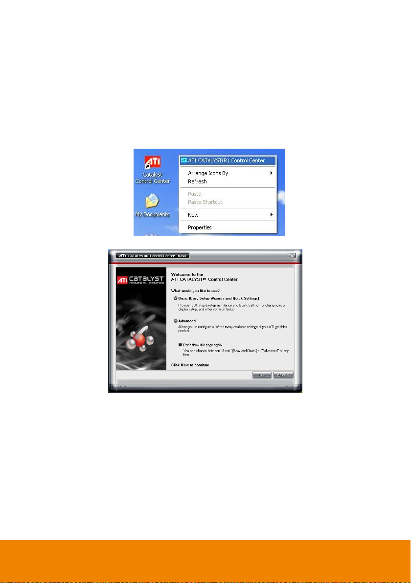
1.2.1 Graphic card with ATi chipset
1. Enter the ATI Catalyst Control Center, user can click the short-cut or right click on the screen.
2. There are two modes to select ─ Basic and Advanced.
3
Page 12
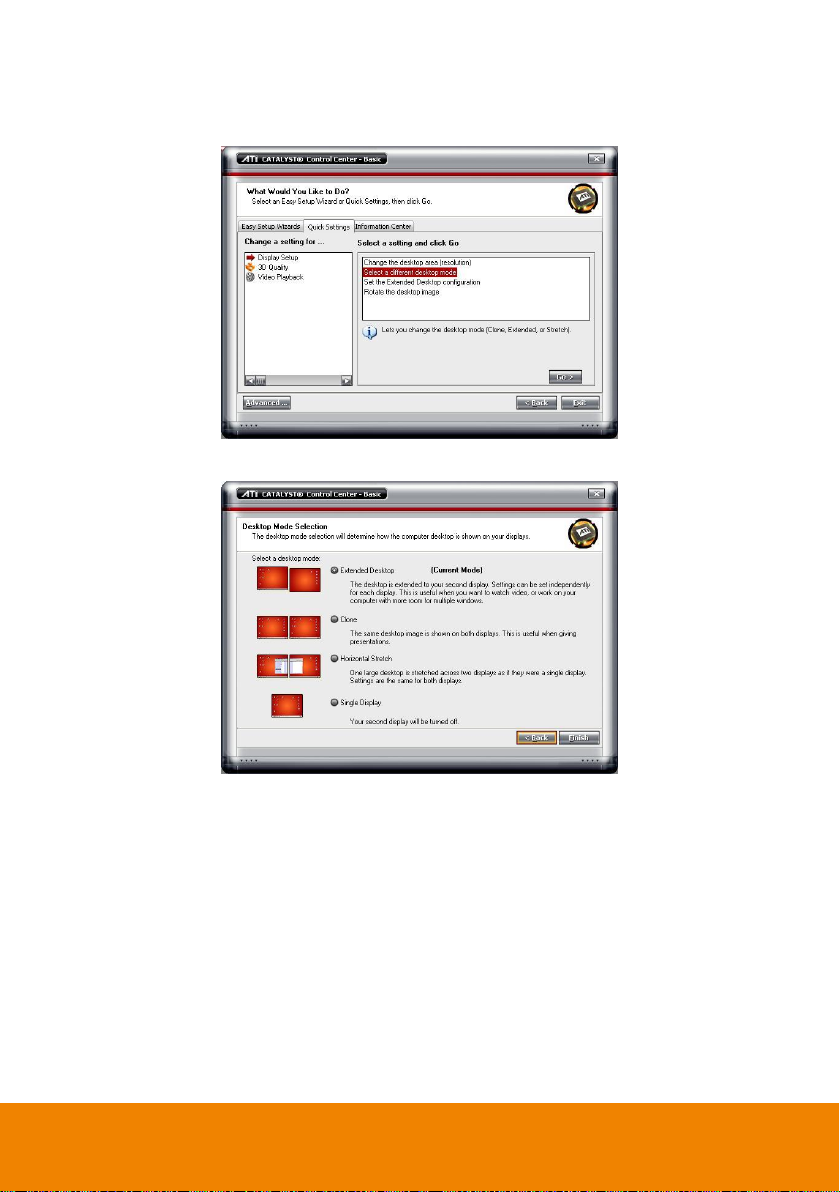
3. If user selected Basic mode, press the Quick Settings tab. Then select the Select a different
desktop mode and click Go.
4. Select the Extended Desktop and then click Finish.
5. If user selected the Advanced mode, click the View button.
4
Page 13
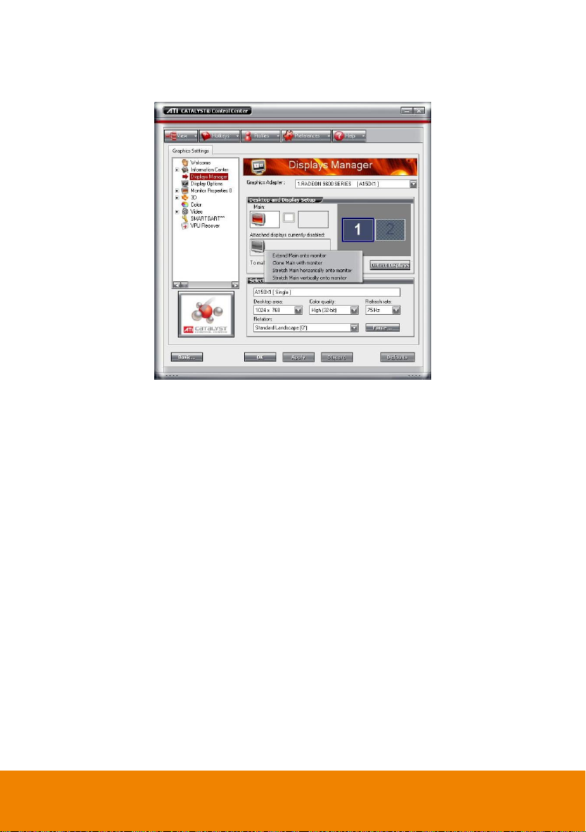
6. In Display Manager, right click on the second Display on the right side and select Extend Main
onto monitor.
7. Adjust each monitor resolution to 1024x768, 1440x900, 1680x1050, 1920x1200 or 1920x1080.
5
Page 14
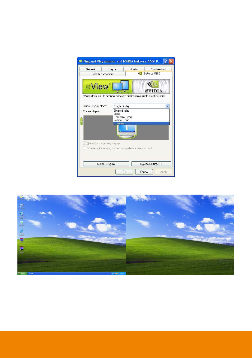
1.2.2 Graphic card with NVIDIA chipset
1. Click the NVIDIA nView, and select the Dualview mode.
2. Adjust each monitor resolution to 1024x768, 1440x900, 1680x1050, 1920x1200 or 1920x1080
3. To review if the display mode is correct, you can check the task bar. The task bar will show on the
first monitor only.
Monitor 1 Monitor 2
6
Page 15

If user has installed AVer NV DVR system already, user doesn’t need to install NXU Lite
again. Please uses NV DVR system to connect AVer IP camera that user has purchased.
Before installing the software, make sure that the Windows OS patches and the video
graphic card driver are UPDATED.
We HIGHLY RECOMMEND having three (3) separate drives for the main system (OS and
NVR software), storage and backup. The ideal hard disk size for the main drive is 20GB.
As for the storage and backup, at least 60GB each. The hard drives format must be in
NTFS. This way we can maintain an optimized system for your security.
i
To ensure getting the latest copy of NVR software, go and download the updated version
from the following site:
Worldwide :
http://surveillance.aver.com/download-center
US/CANADA:
http://www.averusa.com/surveillance/download.aspx
1.3 Software Installation
Please read the following information before install NXU Lite NVR application.
7
Page 16
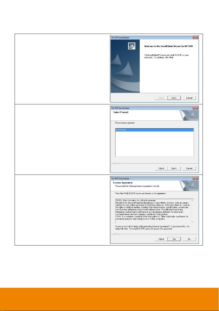
1. Place the Software CD into the CD-ROM
drive then click Install Surveillance
System. Then, click Next to continue.
2. Select the NXU Lite to install and click
Next to continue.
3. Read the License Agreement and click
Yes to accept the agreement. If you do not
agree the license agreement, the
installation will be cancel.
Follow the below steps to install the NVR application:
8
Page 17
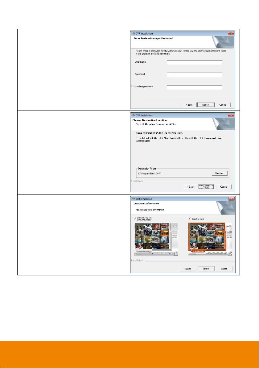
4. Setup the User name and Password for
login NXU Lite system. Re-enter the
password in Confirm password column
and click Next to go next step.
5. Set the install destination, click Browse to
change the default destination folder. If
user doesn’t want to change, then, click
Next to continue.
6. Select the skin color of NXU Lite
application – Titanium Sliver or Electric
Red, then, click Next to start installation.
9
Page 18
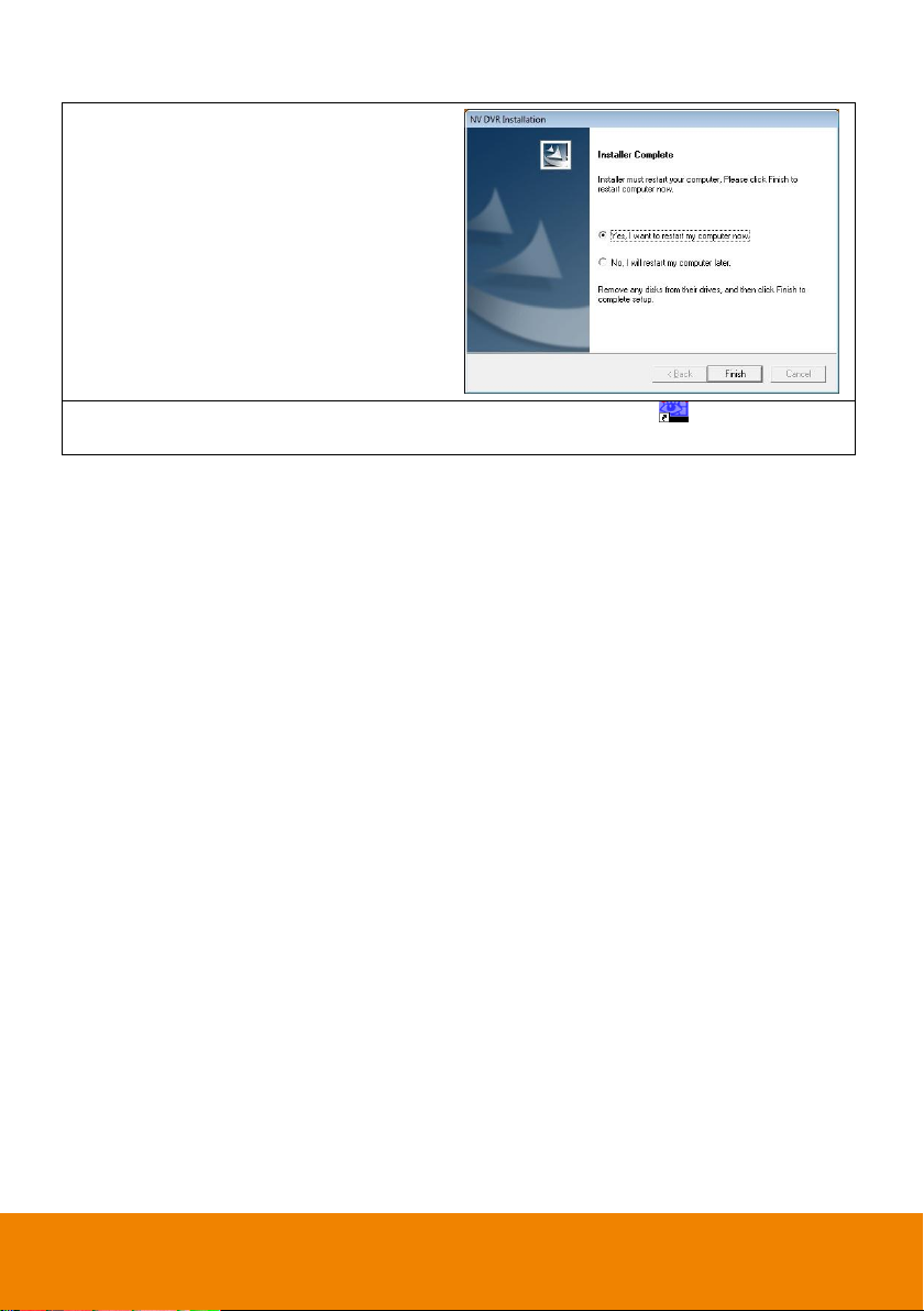
7. After installation completed, user need to
restart your computer. Select “Yes, I want
to restart my computer now” and click
Finish to reboot computer.
8. You may now run the application program. To run the application, click on your PC
desktop or click Start > Programs > DVR > NXU Lite.
10
Page 19
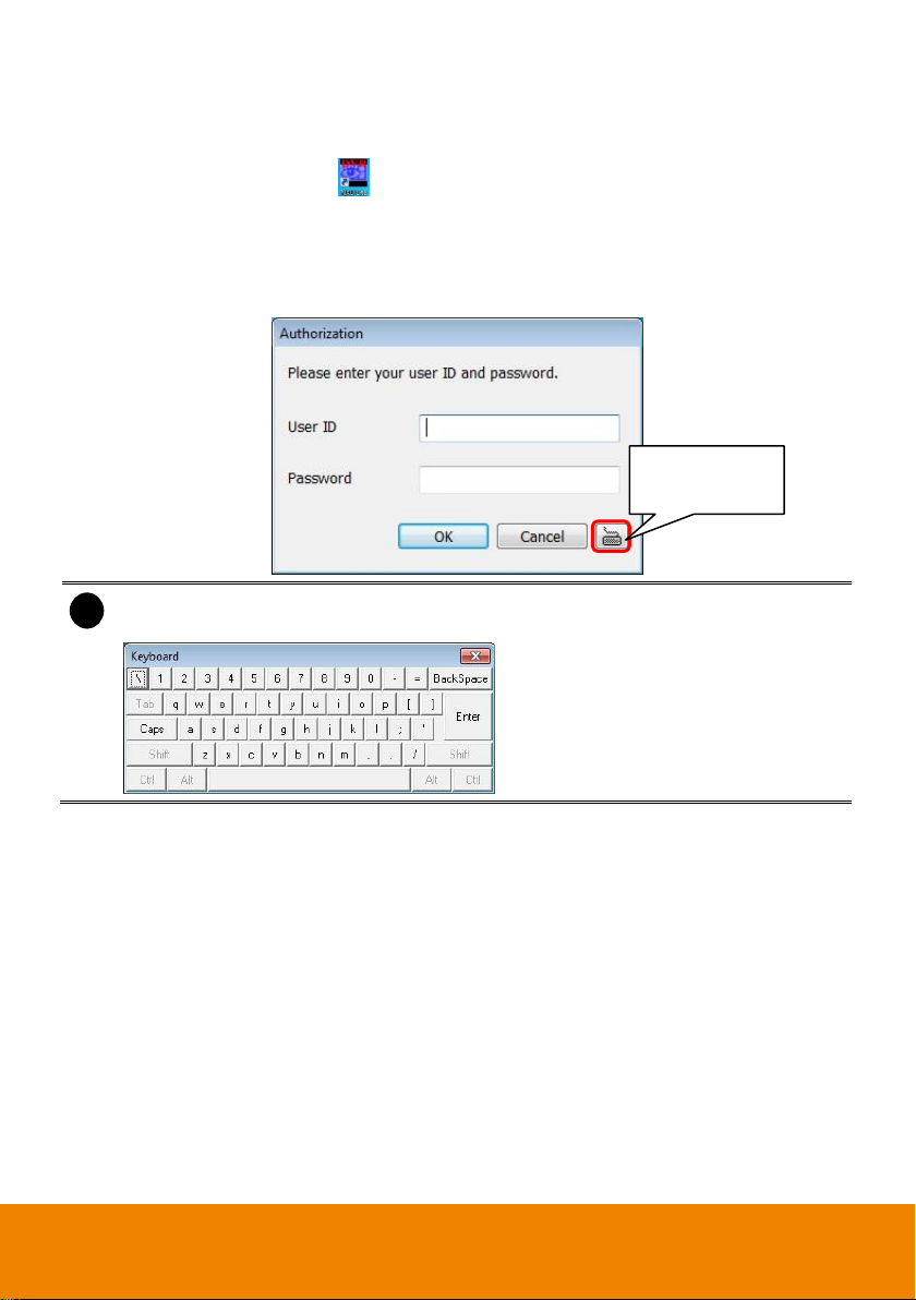
i
Please make sure the cursor is located on User ID or Password column if user has call out
virtual keyboard for entering ID and password.
Click it to call out
virtual keyboard.
1.4 Running the NVR Software
To run the application, double-click on your PC desktop or click Start > Programs > DVR > NXU
Lite.
For security purpose, some of the features would require you to enter User name and Password
before it can be accessed. When the Authorization dialog box appears, key in your User ID and
Password. (If this is the first time, enter the one you have registered when installing the software.)
11
Page 20
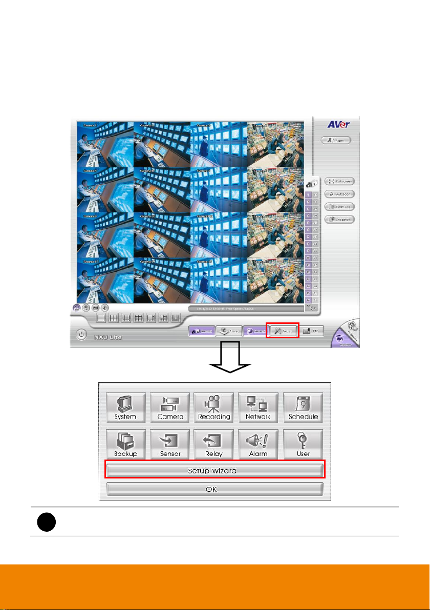
i
User can re-do the Setup Wizard anytime.
Chapter 2 Using the NVR Software
2.1 System Setup Wizard
The Setup Wizard can guide the user to complete the basic but important setting of DVR system.
After login the NVR system, click Setup > Setup Wizard to start wizard.
12
Page 21
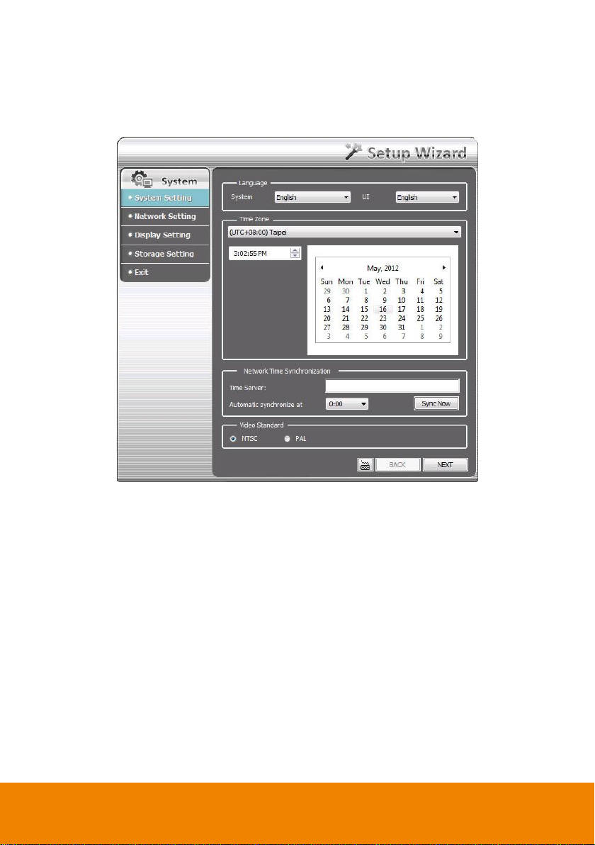
2.1.1 System Setting Wizard
In System Setting step, select the language of DVR system and interface, current time zone of DVR is
located, setup network time synchronization, and select video standard of DVR system.
1. Language: Customize the language for the DVR system, interface, and tool tips based on the
selected language. The default the language is in English.
2. Time Zone: Select the time zone, time, year, and date of DVR is located to setup correct DVR
time.
3. Network Time Synchronization: Adjust the DVR system time same as network time server.
Enter the Time Server IP address or domain name. Select Automatic Synchronize time to set
automatic synchronize time on a daily basis. To adjust time manually, click Sync Now button to
adjust time right away.
4. Video Standard: Change and select the proper video standard according to your camera video
system. If the video system setting is wrong, the video would appear abnormally.
5. Click Next to go to next wizard section.
13
Page 22
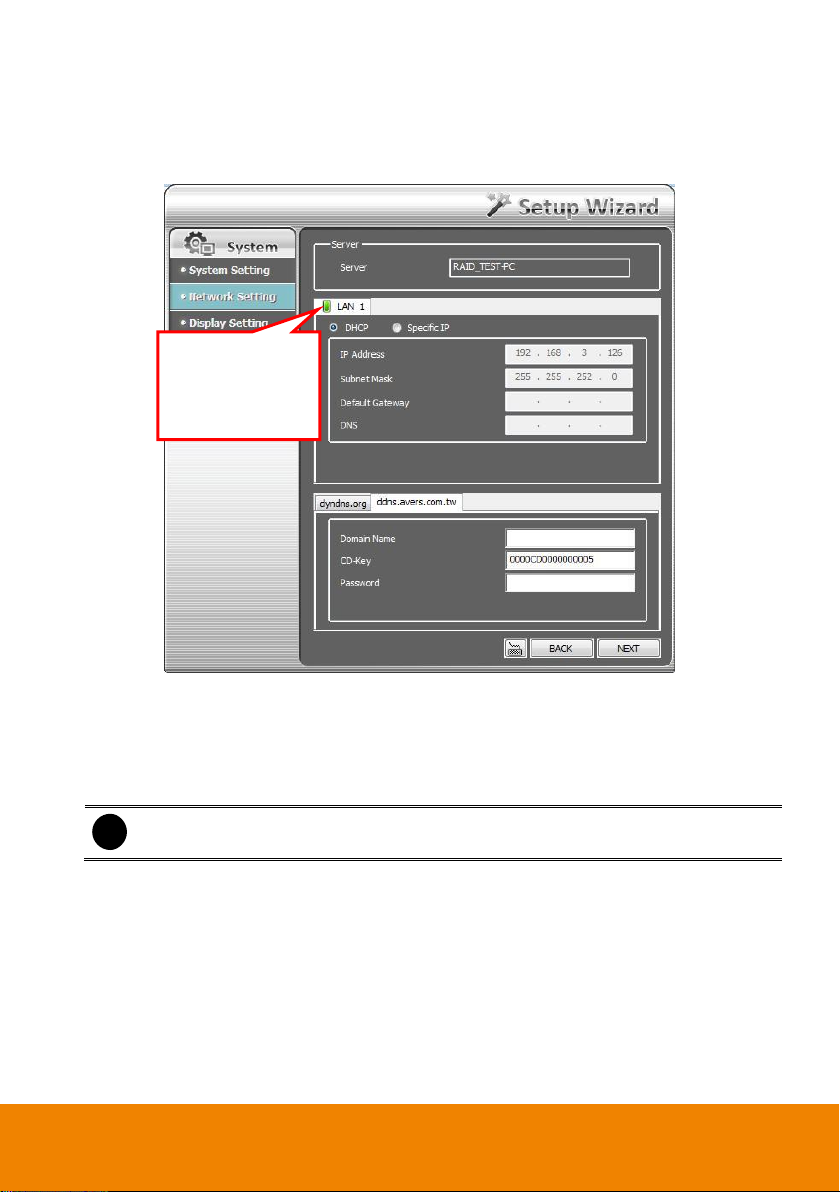
i
Do Not assign the DVR to 1.0.0.0 network segment. It will cause the DVR cannot
access to Internet due to the un-recognize to 1.0.0.0 IP segment.
The green light
indicates the LAN
port is connected
with Ethernet cable.
2.1.2 Network Setting Wizard
Setup the IP address of DVR and configure the DDNS. After completed all configuration, click Next to
save the setting and go to next wizard setting.
1. LAN: Select IP address mode -- DHCP or Static IP.
DHCP: To use DHCP server assigning DVR server an IP address.
Static IP: Assign a fixed IP address for DVR server
- IP ADDRESS: Assign a constant IP address which a real IP addresses give from ISP to
DVR system.
- Mask: It is a bitmask used to identify the sub network and how many bits provide room for
host addresses. Enter the subnet mask of the IP address which user has assigned to DVR
system.
- GATEWAY: A network device act as a passageway to internet. Enter the network gateway
IP address
- DNS: Domain Name Server translates domain names (such as www.abb.com.tw) to IP
addresses. Enter the IP address of DNS if it is available.
2. DDNS setting: To use this feature, go to http://ddns.avers.com.tw or http://dyndns.org and
register.
14
Page 23
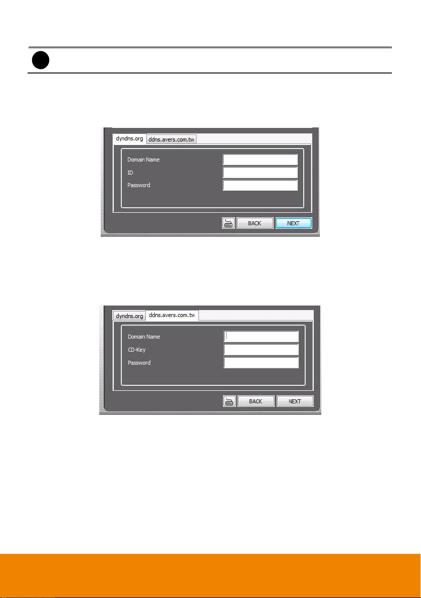
i
The DDNS setting is not required to setup if user hasn’t apply your domain name yet.
dyndns.org
- Domain Name: The user has applied on website www.dyndns.org.
- ID: The account ID that user has created on website www.dyndns.org.
- Password: The password that user has assigned on website dyndns.org.
dyndns.org
ddns.avers.com.tw
- Domain Name: The domain name that user has applied on website ddns.avers.com.tw.
- CD-Key: The CD-Key is located on back panel of DVR unit.
- Password: The password that user has assigned on website ddns.avers.com.tw.
ddns.avers.com.tw
15
Page 24
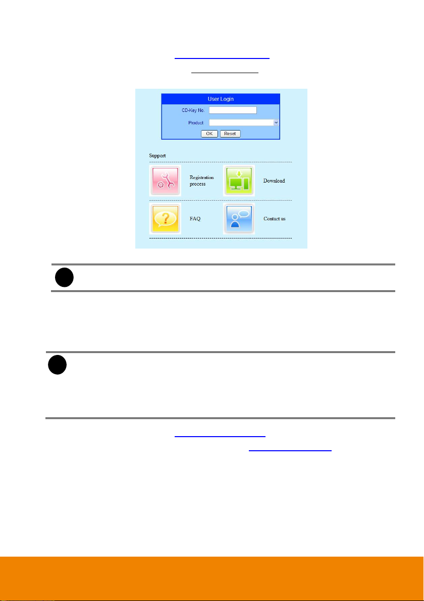
i
One of CD-Key allows user to register two domain names. One of domain name can be
used by Dispatch serve.
i
- Note that Host Name and Domain Name (avers.com) are the replacement for Internet
address while a remote client tends to search a dynamic server.
- Host Name column supports alphabet letters and number only. The maximum character
is 15.
- The password maximum character is 12.
Register the Domain Name on http://ddns.avers.com.tw
1. User Login: Browse the website ddns.avers.com.tw with Microsoft IE or Netscape
Navigator to access the following dialog.
- First input CD-Key number and select the product name.
- Then click OK to login or Reset to clear the previous input.
2. User Information: Please provide the following user information, Host Name (user can
choose any name he/she likes except the one in conflict with other users), Password, E-
mail, Company, and Country. And then, click OK to complete the domain name
registration.
Register the Domain Name on http://www.dyndns.com
1. Open the browser on your PC and enter the URL http://www.dyndns.com
2. Follow the DyDNS’s instruction on website to apply the free domain name.
16
Page 25
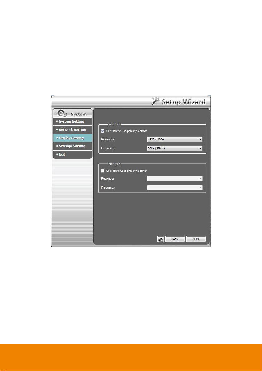
2.1.3 Display Setting Wizard
Set monitor resolution and frequency. The DVR system support dual monitor and user need to set a
primary monitor when using dual monitor mode. The preview UI is displayed on primary monitor
(Monitor 1) and the Monitor 1 sign is displayed at left-upper corner on preview UI screen. The
playback UI and Eamp UI are displayed on monitor 2 and Monitor 2 sign is displayed at left-upper
corner on screen.
Select the Resolution and Frequency from drop-down list and click Next to save the setting and go
to next wizard setting.
17
Page 26
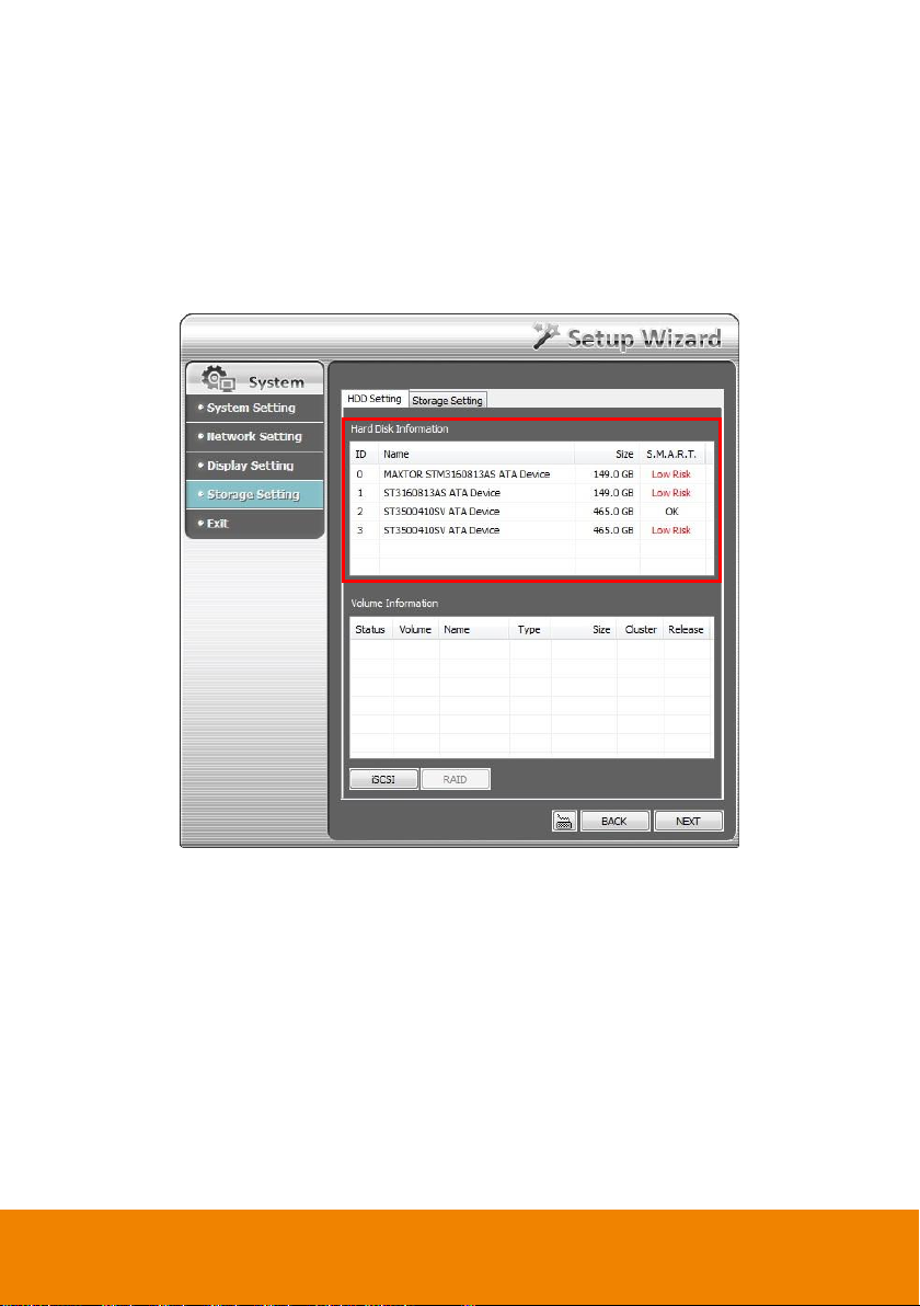
2.1.4 Storage Setting Wizard
To create partition, format the hard disk and select storage path for saving recording data. Also, user
can setup iSCSI for an extra storage capability if user has iSCSI server on your LAN network.
HDD Setting: To create and format hard disk partition, delete a partition, and formatting the hard
disk.
- Create a partition
1. Select the hard disk from Hard Disk Information table.
18
Page 27
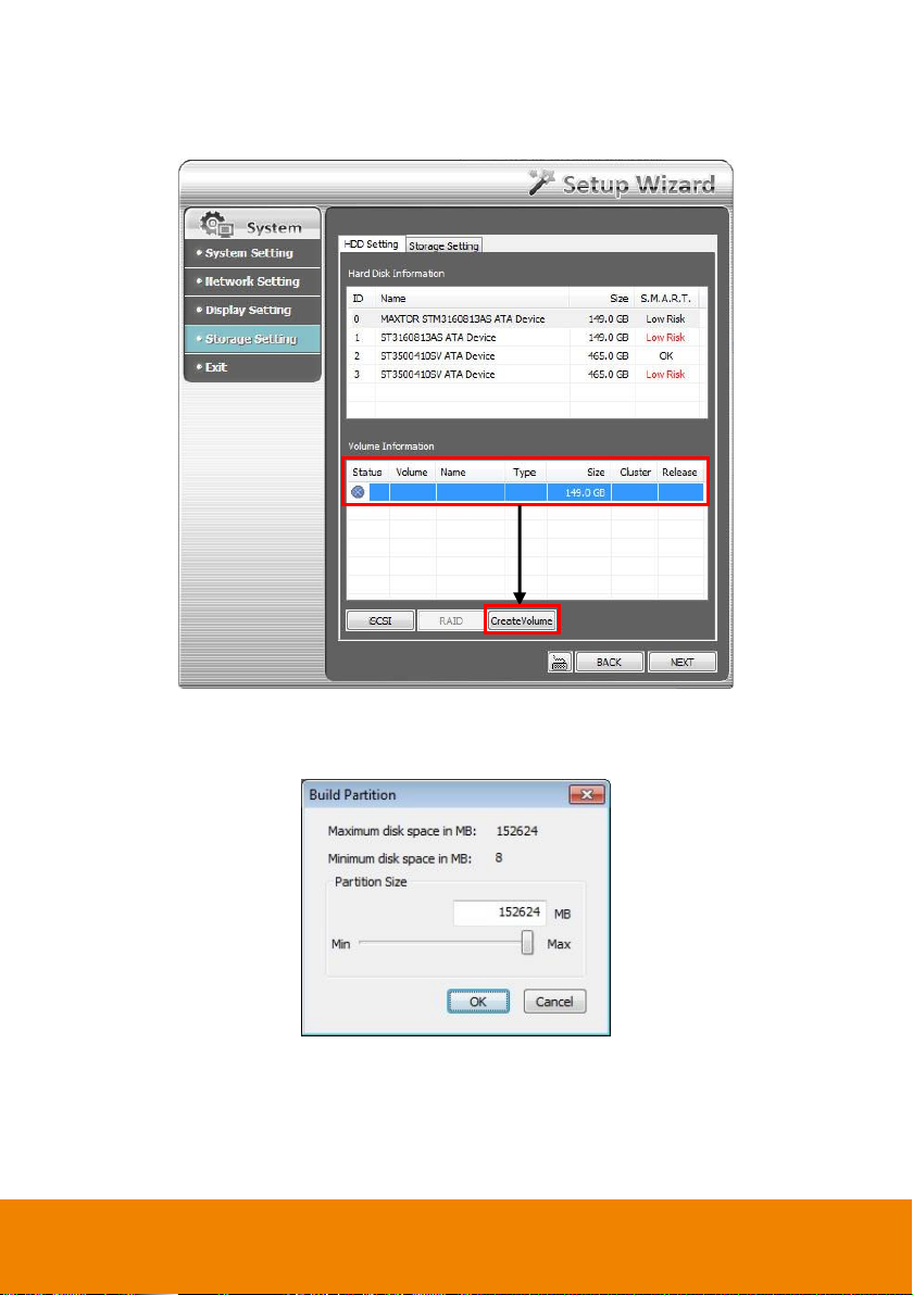
2. Click on the hard disk is in Volume Information table and click Create volume to set the
size of partition.
3. User can enter the partition size or scroll the bar to adjust the size. Then, click OK to create
and format the partition. The created and formatted partition will list in Volume Information
table.
19
Page 28
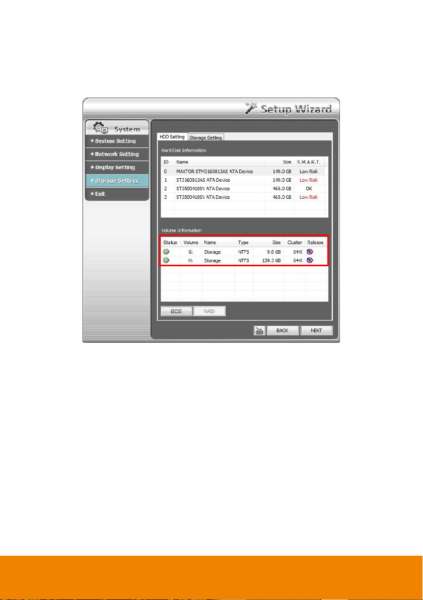
4. Each partition is assigned a letter as a volume ID. When user select a storage path, please
remember the volume ID match to which partition. To select storage path, click Next to go
to Storage Setting page.
5. To create another partition, repeat the above steps.
20
Page 29
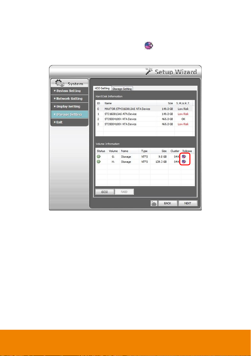
- Release the partition: User can delete the partition. When the partition has been deleted, all
data save in partition will be erased
1. In Volume Information table, click Release icon ( ) of the partition that user wants to
delete it.
2. The DVR system will delete the partition and all data will be erased.
21
Page 30
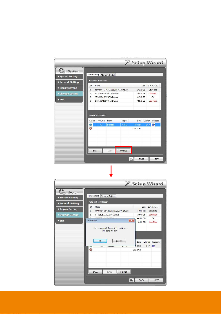
- Format the hard disk: To format a hard disk or a partition. All data on the hard disk or
partition will be erased.
1. Select the hard disk in Hard Disk Information table and select the partition or hard disk that
want to be format in Volume Information table.
2. Then, the Format button will show and click Format button to format it.
22
Page 31

iSCSI: To connect the iSCSI server that user has on LAN network.
1. Click iSCSI button.
2. Enter the IP address or DNS name of the iSCSI server and click Quick Connect to make a
connection to iSCSI server. After connected, user can set the iSCSI server as a storage path.
23
Page 32

Storage Path
Set the directory on where to save the data. When there is not enough free space to record one hour
data, the system automatically replaces the oldest data. In case you have more than one storage path,
the system automatically saves the data to the next storage path.
1. Click button to select a storage path.
24
Page 33

2. In File Browser window, select the hard disk drive from Current Drive drop-down list.
3. Then, click New Folder icon to create a new folder for saving recording data.
4. Click OK to complete it.
5. A storage path will display in Storage Path table. To add another storage path, repeat above steps.
To delete a storage path, select the path and click
button
25
Page 34

6. After completing Storage setting, click Exit button and select Yes to save and exit the Setup
Wizard. If user wants to modify some of setting, select No will back to Setup Wizard.
26
Page 35

2.2 Preview the Live Video
After the successful login, the preview screen will be shown. User can start to connect IP camera,
monitor live video, enable/disable record, change screen display mode…etc.
Regular screen display mode
The NXU List NVR system supports wide screen and regular screen displays and supports 1024x768,
1440x900, 1680x1050, 1920x1200 or 1920x1080 display resolution.
Wide screen display mode
27
Page 36

Name
Function
(1) Exit
Call up the Logout dialog box.
In the logout dialog box, you may do the following:
- Click Exit to close the NVR program.
- Click Reboot to restart NVR system.
- Click Login to sign-in in different account.
- Click About to find about the software info.
- Click Minimize to reduce the NVR to taskbar button.
- Click Compact to switch to compact mode (see Chapter 4.4).
- Click Guest to switch to the guest mode. In guest mode, the functions
are limited to preview function only. For complete functions of NVR,
please login as an administrator.
- Click Cancel to exit Logout dialog box.
28
Page 37

Name
Function
(2) Split Screen
Mode
Select from 7 different split screen types to view all the camera, or one
camera over the other or alongside on a single screen. It also allows you to
switch and view different camera number.
i
- If there are only 4 cameras, you won’t be able to switch to 9, 16, 13, and 32 split screen
mode.
- The NVR system will save the current operating mode (split screen mode, auto scan, full
screen, and compact mode status) when shutdown NVR application and apply the mode
status for next login.
- When you are in single screen mode, Right-click and Drag a square on the area you
want to enlarge. Using left button of mouse click on the enlarge screen area and user
can move the screen for viewing. Right-click on screen again will back to normal view.
- In multiple-screen mode, user can re-arrange the channels’ display order. Right click
the video screen of the channel and Drag on where you want to relocate it. However, the
changed display order of channel only applies in preview mode and wouldn’t apply in
playback.
(3) Record
Start/stop video recording. The authorize password is required for disabling
the record function. The authorization dialog will show the warning
message to inform the user for stop recording.
i
Please make sure the cursor is located on Password column if user
has call out virtual keyboard for entering ID and password.
(4) Emap
Display the map in each area, and the location of camera/ sensor/ relay and
the warning (see also Chapter 2.1.1).
29
Page 38

Name
Function
(5) Network
Enable/disable remote system access. This feature allows you to access
NVR server from a remote location via internet connection. The authorize
password is required for disabling the network function. The authorization
dialog will show the warning message to inform the user for disabling
network.
i
Please make sure the cursor is located on Password column if user
has call out virtual keyboard for entering ID and password.
(6) Setup
Configure the system settings (see also Chapter 3).
(7) PTZ
Access PTZ control panel. Beside PTZ camera, NVR system also support
mega pixel IP PTZ camera (see also Chapter 2.1.3).
(8) Preview
Switch to Preview/Advanced mode. This allows you to view live camera
display. Press ctrl + F can freeze the live preview video screen. And then,
click Snapshot can save the freeze video screen.
(9) Playback
Switch to Playback mode. This allows you to view the recorded video file
(see Chapter 2.3).
(10) Status Bar
Display the current date, time and hard disk free space.
30
Page 39

Name
Function
(11) Camera Group
Tree
To view the user defined channel group tree(see also Chapter 3.2.2). Click
+ of group to extend group and drag the camera to surveillance screen to
view. Click + of camera to view the camera information.
(12) Camera ID
Show the number of cameras that are being viewed. When you are in
single screen mode, click the camera ID number to switch and view other
camera.
(13) Snapshot
Capture and save the screen shot either in *.jpg or *.bmp format.
(14) Event log
Show the record of activities that take place in the system (also see
Chapter 2.1.4).
(15) AutoScan
Start/Stop video screen cycle switch (see also Chapter 3.1 #6).
31
Page 40

Name
Function
(16) Full screen
Use the entire area of the screen to only display the video. To return, press
the right button of the mouse or ESC on the keyboard or click the arrow
icon.
When NVR in full screen mode, each channel will display current date and
time.
When you switch to full screen in multiple-screen mode, Left click to toggle
to only display one of the video in the multiple-screen mode or all.
(17) Alarm
Alert and display warning info. Only Administrator-level can reset and turn
on, off and trigger the Sensor and Relay by right-clicking the item in the
Sensor and Relay list.
(18) Live Playback
button
When live playback function has enabled in Miscellaneous at System
Setting, the live playback icon is appeared on Preview UI while recording
status. Click to playback the recorded file instantly in preview mode.
When the channel is in live playback mode, the icon is . Move the
mouse to the bottom of the live playback channel, the playback tool bar
( ) will show up. Using the playback tool bar to
control the playback. Total 4 channels can be live playback at the same
time.
(19) Volume
Adjust the sound volume.
(20) On Screen
Keyboard
If the keyboard is not available, you may use the Virtual Keyboard.
i
IP camera doesn’t support de-interlace.
(21) De-interlace
To enhance the video quality. Set the de-interlace mode to #1, if you are
capturing motionless picture and #2, if it captures lots of movement.
Click to back to
normal display view.
32
Page 41

Name
Function
(22) Turbo mode
To improve the smoothness of live video. The default is enabled( ), but
in following situation:
- The channel is IPCam and is in 1-split screen.
- The channel is remote NVR and is in 1-split screen.
Turbo function setup is in depended for each channel. To turn off turbo
function ( ), click turbo button.
[Note] In multiple split screen mode, the turbo button is gray out.
33
Page 42

i
The NVR system cannot recognize the file format has been changed. Please do not
change the *.tif or other file format to *.bmp/*.jpg file format.
i
- The NVR only supports 24-bit and 32-bit bmp and jpeg file.
- The map file size is no more than 200K.
2.2.1 Setting Up and Using the Emap
Emap can hold up to 8 maps in *.bmp/*.jpg format. You may locate the camera, sensor and relay on
the map.
To Set Up the Emap
1. Click Emap.
2. When the Emap screen appears, click the area number (1 to 8 buttons) on where you want to
insert the map.
3. Click Load Map to insert the map. When the open dialog box appears, locate and select the map
and click Open.
4. When the inserted map appears on the Emap screen, click Edit. You may now drag the camera,
sensor, and relay icons to its place on the map. Icons on the map can be relocated anywhere.
5. To set the camera direction, right click camera icon can select the camera direction in 8 angles.
6. If you are going to locate the icon on the map to other area, you need to drag the icon to the
black pane at the bottom of the Emap screen and then switch to the area on where you want to
locate the icon. To bring all the icons back to the black pane at the bottom of the Emap screen,
click Reset Icon.
7. When you are done, click Save button to save the new setting. To close Emap screen, click X.
34
Page 43

2.2.2 To Use the Emap
1. Click Emap.
2. In the Emap screen, click the camera icon to switch on the area where the camera is located on
the map and to display the video at the upper right corner of the Emap screen. At the lower right
corner of the Emap screen, it lists all the warning message.
3. To control relay, right-click relay icon and select status (on, off, or trigger) of relay.
4. To view different Emap, click Emap number button (1 ~ 8).
5. Click X to close Emap screen.
35
Page 44

(9) (8) (7) (6) (5)
(2)
(1)
(3)
(4)
(10)
(11)
Name
Function
(1) Close
Exit PTZ camera controller.
(2) Camera preset
position number
Move the PTZ camera to the preset point.
(3) Group AutoPan
Select to automatically operate PTZ camera in group.
(4) Direction buttons’
moving speed
Adjust the moving speed of the PTZ camera lens. This speed will apply
to the (11) Direction buttons’ moving speed only.
(5) Save Camera
preset position
Save the PTZ camera preset position number. Select the camera and
click the preset position number and save it.
(6) Setup
Configure PTZ cameras (also see Chapter 2.3.7).
(7) AutoPan
Operate the PTZ cameras automatically based on the selected camera
group preset position number. User needs to select the (3) Group
AutoPan, then, click (7)Auto Pan button.
(8) Zoom +/-
Zoom in and out the image.
(9) Focus +/-
Adjust the focus manually to produce clear image.
(10) Camera ID
Display the PTZ camera number that is being operated.
(11) Direction buttons
Move and position the focal point of the PTZ camera. The support of
direction button depends on the PTZ camera.
2.2.3 Familiarizing the Buttons in PTZ Camera Controller
36
Page 45

i
- NVR system now supports HDD failure pre-detection mechanism called HDD S.M.A.R.T.
function. Once when NVR system has detected the HDD failure possibility, an event log
will be occurred and user can check it in Event Log Viewer window.
- The HDD S.M.A.R.T. function accurate is approximately about 60%.
- The HDD warming event log will issue once a day.
i
HDD S.M.A.R.T. warning messages’ description are as following:
- HDD warning (Low risk): abnormal situations are occurred frequently but hard disk can
recovery by itself.
- HDD warning(High risk): When HDD warring(Low risk) event has occurred too
frequently, even though hard disk can recovery by itself; however hard disk recovery too
frequently will effect performance of hard disk. Therefore, it is recommended to replace
the hard disk.
[Note] HDD S.M.A.R.T. is an accumulation mechanism, therefore the HDD warning
(High risk) event log will issue once every day until hard disk has been replaced.
2.2.4 Using Event Log Viewer
Show the record of activities that take place in the system.
1. Click the Event Log button on NVR application main interface. The Event log viewer window will
show up.
37
Page 46

2. Select the Date to view or search certain event log by key word. Enter the key word in Find Text
column and click Search button.
3. To filter the records, select and click the select button to display Event, System, Operation,
Network or All.
4. The events list which display on the screen can be saved as text file format. To save the events list,
click Save button.
38
Page 47

Name
Function
(1) Split Screen
Mode
Select from 7 different split screen type to view all the camera, or one camera
over the other or alongside on a single screen.
i
- If there are only 4 cameras, you won’t be able to switch to 9, 16, 13, and 32 split screen
mode.
- When you are in single screen mode, Right click and Drag a square on the area you
want to enlarge.
- When you are in multiple-screen mode, Right click the video screen of the camera and
Drag on where you want to locate it. To only display one of the video in the multiplescreen mode, Left click the video screen you want to display.
2.3 Using the NVR System in Compact Mode
Compact mode provides bigger monitor view and less function buttons. To view in Compact mode,
click Exit button. In the logout dialog box, click Compact.
39
Page 48

Name
Function
(2) AutoScan
Start/Stop video screen cycle switch
(3) Alarm
Alert and display warning information.
(4) Playback
Switch to Playback mode. This allows you to view the recorded video file. (see
Chapter 2.3)
(5) Advanced
Switch to Preview/Advanced mode.
40
Page 49

2.4 Playback the Recorded Video
To switch in Playback mode, click Playback button at the lower right corner of Advanced/Preview
mode user interface.
In wide screen mode, click button call out the progress bar. According color of progress bar, user
can know the recording file type. Blue means regular recording file. Green means motion recording file.
Yellow means video loss while recording. Red is alarm triggered while recording. Black is no record
data.
41
Page 50

Name
Function
(1) Split Screen Mode
Select from 6 different split screen type to playback the recorded video
file of all the camera, or one camera over the other or alongside on a
single screen.
i
- If there are only 4 cameras enabled, you won’t be able to switch to 9, 16, and 13 split
screen mode.
- To zoom in an area on the screen, Right-click and Drag a square on the area you want
to enlarge. Left-click on the enlarge screen area and user can move the screen for
viewing. Right-click on screen again will back to normal view.
(2) Exit
Close the Playback application.
42
Page 51

Name
Function
(3) Progress bar
Show the progress of the file being played. You may move the bar to
seek at any location of the track.
When in single screen playback mode, the colors in progress bar have
different means.
Green color: a motion was detected and recorded
Blue color: is a general (always) recording file and no any event or
motion happen during recording
Red color: the sensor was triggered while recording
Black color: no record file at the time period
Yellow color: the video loss happen while recording
i
The progress bar is designed and drawn based on key frame only.
(4) Hour Buttons
Select and click to playback the recorded video file on the specific time
frame.
i
The Hour buttons represent the time in 24-hour clock. The blue bar on top of the hour
button indicates that there is a recorded video file on that period of time. While the red bar
indicates that you are currently viewing the recorded video file.
(5) Playback Control
Buttons
Begin: Move at the beginning of the recorded video file.
Previous: Go back to the previous frame.
Slower: Play the recorded video file at the speed of 1/2X, 1/4X, 1/8X,
1/16X, or 1/32X.
Rewind: Wind back the recorded video file.
Pause: Briefly stop playing the recorded video file.
Play: Play the recorded video file.
Faster: Play the recorded video file at the speed of 2x, 4x, 8x, 16x or
32x.
Next: Go to the next frame.
End: Go to the end of the recorded video file.
i
While faster play status, press play button, then, the play speed will back to normal
playback speed (1x).
43
Page 52

Name
Function
(6) Archive
Select the date on the calendar and the time from 00 to 23 to where to
start playing the recorded video file.
– OPEN FILE: user can open the recorded file from HDD
– Channel 01~ 16&Channel 17 ~ 32: Switch to different channel group
of playback calendar.
– Day Light Saving: the playback calendar will show the available
video records during day light saving time period.
i
The numbers from 00 to 23 represent the time in 24-hour clock. The numbers from 01 to
16 represent the camera ID. The blue colored column indicates that there is a recorded
video file on that period of time. While the red colored column indicates on where to start
playing the recorded video file.
(7) Status bar
Display the recorded date, time and play speed.
(8) Camera ID
Show the number of cameras that are being viewed. When you are in
single screen mode, click the camera ID number to switch and view
other camera.
(9) Export
Export includes Snapshot, Print, Output Video Clip, and Backup function.
Snapshot: Capture and save the screen shot either in *.jpg or *.bmp
format.
Print: Print the screen shot.
Output Video Clip: Save the segmented file in *.mpg, *.avi, or *.dvr
format (see also Chapter 2.3.1).
Backup: Save the playback file to USB device or DVD-ROM disk(see
also Chapter 5.6 Backup Setting)
(10) Segment
Keep a portion of the recorded video (see also Chapter 2.3.1).
44
Page 53

Name
Function
(11) Full screen
View in Playback-compact mode. To return, press the right button of the
mouse or ESC on the keyboard or click the arrow icon.
When you switch to full screen in multiple-screen mode, Left click to
toggle to only display one of the video in the multiple-screen mode or all.
i
When there are dual monitors with 32 channels, the full screen mode will split into 16
channels on each monitor.
(12) Event log
Show the record of activities that take place in the system. To filter the
records, select and click the option button to only display Event, System,
Operation, or Network.
(13) Bookmark
Mark a reference point when previewing the recorded video file to which
you may return for later reference. You may also set it to protect the file.
(See also Chapter 2.3.2)
(14) Visual Search
Search from a specific camera by Date, Hour, Minute, 10 Seconds and
Second. (See also Chapter 2.3.3)
(15) Find Next
Search for the next event or changes in the motion detector frame. You
can use this when you are using Intelligent Search or Event Search
function.
(16) Event Search
Search from the recorded activities that take place in the system (i.e.,
Sensor, Motion, Video Loss). (See also Chapter 2.3.4)
(17) Intelligent Search
Search the changes in the motion detector frame (See also Chapter
2.3.5).
(18) Audio
Enable/disable volume. To adjust audio volume, drag and move the
audio volume bar beside the audio button.
45
Page 54

Name
Function
(19) De-interlace
To enhance the video quality. Set the de-interlace mode to #1, if you are
capturing motionless picture and #2, if it captures lots of movement.
i
IP camera doesn’t support de-interlace.
(20) Watermark
To verify the playback video has not been modified (also see Chapter
2.3.6).
(21) Turbo Mode
To improve the smoothness of live video. The default is enabled( ),
but in following situation:
- The channel is IP camera and is in 1 single screen.
- The channel is remote DVR and is in 1 single screen.
- The channel is analog camera, in 1 single screen, and decoding way
is software decode
Turbo function setup is in depended for each channel. To turn off turbo
function ( ), click turbo button.
[Note] In multiple split screen mode, the turbo button is not functional.
46
Page 55

i
- MPGE format doesn’t support audio output.
- Right-click function is disabling for security issue.
2.4.1 To Cut and Save the Wanted Portion of the Recorded Video
1. Use the Playback Control buttons or drag the bar on the playback progress bar and pause on
where you want to start the cut. Then, click Segment to set the begin mark.
2. Use the Playback Control buttons or drag the bar on the playback progress bar and pause on
where you want to end the cut. Then, click Segment to set the end mark. To cancel
segmentation or set the segment marks from the start, click Segment button again.
3. Click Export → Output Video Clip button to save the wanted clip.
4. In the Save As dialog box, locate on where you want to save the file or choose to Burn the video
segment to VCD/DVD ROM (only for .*mpeg file format).
5. Select the file type and mark “show camera information” to display the camera name,
recording date, and time on screen when playback. If user doesn’t mark this option, the camera
name, recording date, and time won’t be shown on screen when playback.
6. If the select the file type is *.avi, user can mark included audio to include audio in output video
segment.
7. To adjust Video Quality if needed.
8. Click Save to save the video segment.
47
Page 56

2.4.2 To Bookmark a Section of the Video
1. Click Bookmark. The video playback stops when the bookmark button is executed.
2. In the Bookmark dialog box, you may do the following:
3. Add to include the new reference mark in the bookmark list. You may select to enable/disable File
Protect to protect the bookmark file for overwritten.
If user has select to enable the file protect, a message dialog will show up to let user to choose to
delete protect file or not to delete file when the recycle function has setup (see also 3.1 System
setting). Click Yes to allow protect file to be deleted, click No the protect file will not be deleted
even the recycle function has enabled.
- Edit to change the mark description or enable/disable file protection.
- Delete to remove the selected reference mark in the list.
- Delete All to remove all the reference marks in the list.
- Exit to close Bookmark dialog box.
4. Select and click one in the bookmark list to preview the file.
48
Page 57

2.4.3 To Search Using the Visual Search
1. Click Visual Search.
2. In the Visual Search Setting dialog box, select the Camera number and the date. Then click OK.
3. When a series of frames appear by date, click on the frame to display another series of frames
and search by every Hour of that date, every 3Minutes of that hour, every 10 Seconds of that
minute, every Second of that 10 seconds. To go back, click . To view from the selected
frame and close event search, click .
49
Page 58

2.4.4 To Search Using the Event Search
1. Click on the video screen on where you want to search.
2. Click Event Search. The Event Search text (red) would appear at the lower left corner of the
screen.
3. In the Event Search Setting dialog box, check the type of condition you want to search. Then,
click OK to start searching. The video search would stop at the frame that matches the condition.
To keep on searching click .
4. You may also set to search and list all the result. Just check the Output Event List box. In the
Search Duration section, set the Begin Time and End Time. Set the Searching Interval time
that system won’t list out the same events in a period of time that user has setup. Then, click OK
to start searching.
5. When the Event list appear, click and select the item you want to view.
50
Page 59

2.4.5 To Search Using the Intelligent Search
1. Click on the video screen on where you want to search.
2. Click Intelligent Search. The Intelligent Search text (red) would appear at the lower left corner of
the screen.
3. When the Intelligent Search Setting dialog box and motion detector frame appear, you may adjust
the sensitivity bar and the motion detector frame size and location. To set motion detector frame
size and location, left click and drag on the screen. Then, click OK to start searching. The video
search would stop at the frame that matches the condition. To keep on searching click .
You may also set to search and list all the result. Just check the List box. In the Search Duration
section, set the Begin Time and End Time. Set the Searching Interval time for in a period of
time won’t list out the same events. Then, click OK to start searching. The search result will show
as below figure:
51
Page 60

i
Watermark verification doesn’t support the video that is recorded from MPEG IP camera.
2.4.6 Watermark Verification
Now, NVR supports watermark-checking to identify the authenticity of playback video. NVR program
can only verify one channel at a time in playback mode.
To verify the playback video doesn’t been modified. Click to check the video. Watermark
verification window will show up as following:
52
Page 61

i
The numbers of preset position are depended on the IP camera protocol has supported.
Use to adjust
the lens of PTZ
camera for
preset position
setting.
2.4.7 To Setup the IP PTZ Camera
1. In the PTZ control panel, click Setup.
2. When the PTZ Setup dialog box appears, click IP PTZ tab.
3. Select the camera number and mark the Use PTZ check box.
4. In the Connection Settings section, select the Protocol and Model that is brand of IP PTZ camera
and enter the IP or URL of IP camera in IP Camera Site column. Mark the Authentication box if
ID and Password is required when connecting to IP PTZ camera. And then, click Save to keep
the settings.
5. In the Preset Setting section, use the control panel and adjust the position of the PTZ camera
and select the preset number to assign a number for the PTZ camera current position.
6. Set the DwellTime (1-60 sec) for how long the IP PTZ camera stays in that position before it
moves to the next one. If you want to add description, check the Show Preset Name box and in
the Preset Name text box, type the word. After is done, click Save to keep the settings.
7. Repeat step 5 & 6, if you want to save another IP PTZ camera position.
8. Restore AutoPan Time: set a time period for restoring auto path function after the IP PTZ
camera has been moved. Mark the check box and set the time period in second. Set the AutoPan
Speed if the IP PTZ camera that user has used is supported.
9. Others: Enable/disable Using Joystick such as USB joystick device.
53
Page 62

i
User can move the on screen PTZ control panel to any position of screen
10. Show moving direction indicator line: enable/disable to show the direction line when uses
mouse drag on screen in PTZ mode.
11. Iris: To adjust the iris of IP PTZ camera. It may not support that depends on brand of the PTZ
camera.
12. OSD: To allow call out IP PTZ camera factory’s OSD setup menu. The OSD setup menu may vary
that depends on the brand of IP PTZ camera.
13. When is done, click OK to save the setting or Click Cancel, to leave without saving the new
setting.
14. When PTZ camera is enabling, user can control PTZ camera by using the mouse and on screen
PTZ control bar.
15. Click the channel that has supported and enabled the PTZ function. And then, click PTZ button on
preview UI. The PTZ control panel will show up on the screen.
54
Page 63

16. User also can click PTZ icon to call out on-screen PTZ control bar and use mouse to drag on
screen to move the PTZ camera lens direction.
17. In PTZ screen mode, right-click and drag can enlarge the selected area. After enlarged area, left-
click can move screen to left and right (User should see a hand icon on screen). To return to
normal view, right-click on screen again.
55
Page 64

Chapter 3 Customizing the NVR System
In the Preview/Advanced screen mode, click button to customize your NVR. When the NVR
configuration setup selection appears, select and click the buttons you want to change the setting.
3.1 System Setting
In the System Setting dialog box, click OK to accept the new settings, click Cancel to exit without
saving, and click Default to revert back to original factory setting.
(1) Storage Path
Set the directory on where to save the data. When there is not enough free space to record one hour
data, the system automatically replaces the oldest data. In case you have more than one storage path,
the system automatically saves the data to the next storage path. You may also add additional
network-attached storage (NAS) for extremely high storage capacity. Select the Enable network
storage check box to send the recorded video in network-attached storage. To add network storage,
the Internet storage drive/folder must be mapped as Network Driver in NVR server.
56
Page 65

i
When using the network storage path, the performance of NAS equipment and your actual
network bandwidth might impact the recording and playback performance of the NVR
server.
Enable network storage first, and then, click Add. In Browse For Folder window, select drive C and
right click mouse button, select Map Network Drive option.
In the Map Network Drive window, select the Drive and fill in the network drive direction in Folder
column if you know. Or click Browse to find the folder direction. Click Finish to complete the network
drive mapping. After the network drive has been added, user needs to create a folder for network
storage. In Browse For Folder window, select the network drive and right click mouse button to add a
new folder. And then, click OK. User should see a new storage folder display in Storage path list.
By default the data is stored in C:\Data, to insert another storage path, click Add. To remove the
selected path, click Delete. If you want the system to automatically erase the data after a certain days,
enable the Delete recorded data after check box and enter the numbers of days in Days text box. If
you want the system to automatically erase the event and alarm log after a certain days, enable the
Delete event and alarm log after check box and enter the numbers of days in Days text box. To
change logs save direction, enable Move to and select the new save path.
57
Page 66

(2) Hard Disk Calculator
Estimate the hard disk recording capacity. The result of calculation is a rough value which only for
reference. The hard disk record capacity will be varied by the real record quality and complexity of
video scene.
Click , the hard disk calculator window will show up. Total Recording time is the current hard disk
recording capacity. Enter the expect hard disk size or expect recording time in Expected HD Size or
Expected Record time, and then click Calculate button. Click OK to exit the hard disk calculator
window. The hard disk calculation is based on the recording setup and current hard disk setup.
(3)Language
Customize the system to display the tool tips and dialogs based on the selected language. By default
the language is in English.
(4) Configuration
Backup a copy of all the settings and allows you to regain the same settings back. To save the current
settings, click Export. To replace the settings with the one you have saved, click Import. The export
and import file will include Emap configuration.
(5) Help
Click to call out the user’s manual. The manual format is PDF format, please make sure your PC has
installed Adobe Acrobat reader and version is 7.0 above.
(6) Login
Enable the conditions in Login section you want the system to automatically carry out.
- Auto Login when OS start
Execute the NVR when the operating system is started.
- Ask for password when login
Request to enter User ID and Password each time the NVR is executed.
- Auto record when login
Automatically start video recording when the NVR is executed.
- Auto start Network when login
Automatically enable NVR network connection when login into NVR program.
- Login to compact mode
Switch to compact mode directly when the NVR is executed.
58
Page 67

- Silent Launch
Enable the NVR system minimizes on the system tray automatically right after start up.
- Guest Mode
Automatically log in Guest mode when the NVR is executed. In guest mode, the functions are
limited to preview and playback only.
- Default user
Automatically log in to the selected default user when the NVR is executed.
(7) Miscellaneous
Enable the conditions in Miscellaneous section you want the system to perform.
- Status Report
Send a daily system event and attention analysis report. To change the e-mail settings, click
Setup.
- Desktop Lock
Block window OS hotkey: Deactivate the [Ctrl-Alt-Del] and [Windows] keyboard key
functions.
Block windows OS pop-up window: To block any pop-up window from windows system.
59
Page 68

i
In 64bit Windows OS, Increase memory usage of process function is enabled in default.
In 32bit Windows OS, user need to enable the Increase memory usage of process function
manually.
- Beep if no signal
Make sound when the video signal is lost.
- Shutdown OS when exit
Turn off the PC when the NVR application is being closed.
- Mandatory Record
Always record video when software is running
- Enable Liveplayback
Mark to enable live playback function on Preview UI when start to record. User should see the live
playback icon( ) on Preview UI.
- Increase memory usage of process
The NVR system supports 42 MP resolution in total for all IP camera channels. When Increase
memory usage of process function is disabled, the NVR system only supports 24MP resolution in
total for all IP camera channels.
- Screen Saver
Set a period time to enter screen saver mode when system idle.
- Leave the system without asking user name and password
Don’t need to enter password when close/exit NVR program.
- Resequence channels when autoscan
The NVR system will re-arrange the channels order if some of channel is disable when auto scan
is enabled. For example, CH 1 and 3 is disable, the channel will display in order of
CH2,4,5,6,7~16. The CH1 and 3 won’t be shown on screen when auto scan is enabled.
- Remember playback display mode
To memorize the last playback status. The NVR system will memorize the playback status from
last time that user has selected or setup for next time playback.
- Auto Scan Period
Set the time gap of the Auto Scan function from 3 to 10 seconds. This automatically switches to
the next video in cycle depending on the set time gap.
- Playback Mode
Select the mode of playback the video.
Select date and time: Select the date and time which user wants to playback.
Play the last file: Automatically playback the video from the last hour
Instant Playback: Automatically playback the video which has just recorded. To set the instant
playback time period, fill in the time in second at Set Instant Playback’s Play Time column.
- Date Format
Select the date format which wants to display in Select date and time playback mode
60
Page 69

i
The UPS application must meet Windows XP and Windows 7 system requirements.
(8) Dual Monitor
Enable/disable dual monitor display. Click Setting to select display order of Preview (main system),
Playback, and EMap.
(9)UPS (Uninterruptible Power Supply)
Protect the system from damaging, such as power surges or brownouts. This automatically gives time
to close the NVR properly when the battery backup power has reached the Shutdown when capacity
below percentage level setting. The UPS device must be connected to your computer (refer to your
UPS user’s guide).
61
Page 70

(10) System Configuration
The System Configuration is in different display on Window XP and Windows 7. Following are
described System Configuration function on Windows XP and Windows 7.
Window XP
To configure the DVR system date, time and IP address.
Display Setting
To adjust resolution of display.
62
Page 71

i
- Please stop recoding before formatting HDD.
- The hard disk has been added into storage path that is not able to re-format and
partition.
HDD Management
To manage and format the hard disk is installed inside the DVR system. The DVR system can
format the HDD that is the first time install on DVR system. The DVR system supports iSCSI hard
disk.
To format and partition hard disk:
1. Click + button to add the selected hard disk into Partition Table section.
2. User can adjust the capacity of partition by clicking Capacity column and enter the capacity. If
user doesn’t want to divide hard disk into several partitions, and then, just leave the capacity
without change.
3. The partition can be named by clicking on Label column and enter the name.
4. To create more than one partition, do the steps 1 and 2 again.
5. When all the partition has been added, click Start to format all partitions.
6. When the formatting complete, the each partition status will change to OK.
7. Click OK to exit when formatting is completed.
8. Now, user can assign formatted hard disk or partition as a storage path( see also Chapter 5.1
System setting(1)Storage Path)
63
Page 72

i
Do Not assign the DVR to 1.0.0.0 network segment. It will cause the DVR cannot access to
Internet due to the un-recognize to 1.0.0.0 IP segment.
Network Setting
To configure the network setting (IP address, subnet, DNS, and son on…) of the system.
Obtain an IP automatically (DHCP): To use DHCP server assigning DVR server a IP address.
Using the following IP address: Assign a fixed IP address for DVR server
-
IP ADDRESS: Assign a constant IP address which a real IP addresses give from ISP to
DVR system.
-
Mask: It is a bitmask used to identify the sub network and how many bits provide room for
host addresses. Enter the subnet mask of the IP address which user has assigned to DVR
system.
-
GATEWAY: A network device act as a passageway to internet. Enter the network
gateway IP address
DNS: Enter the IP address of DNS
-
64
Page 73

Map Network Drive: To add network storage, the Internet storage drive/folder must be
mapped as Network Driver in DVR server. Follow the below steps to map the network drive.
1. Click Map Network Drive button. In the Map Network Drive window, select the Drive and
fill in the IP address and file folder of file server or NAS on your network in Folder.
2. And then, click Finish to make the connection.
3. After connection successful, user should see the network drive on the Storage Path.
4. To disconnect the mapping network drive, click Disconnect Network Drive.
Ping IP: Allow user to ping and trace the certain IP address of network/server device on the
network.
65
Page 74

Audio Setting
To adjust audio volume of system.
Others
66
Page 75

Printer Setting
Click Add Printer and following the wizard to install a printer.
Regional/Language Setting
When DVR application is using different language of UI besides English, user can select the
corresponding region and language in order to make UI display correctly.
67
Page 76

Power Management
To configure UPS. Click Select… to select the UPS that has connected with DVR system.
Device Management
To manage the DVR system devices.
68
Page 77

Network Connection
To manage the connection of the network.
Phone and Modem options
To setup the modem dial-up settings.
69
Page 78

Date/Time Setting
1. Select the Time Zone of DVR server located
2. Select the Month and Date. Click arrow button can switch to different month.
3. Adjust the Time by click spin box arrow button.
4. Click OK to save the configuration.
Usageinfo
To view usage of the system CPU, memory, and network.
70
Page 79

Windows 7
In System Configuration section, user can setup keyboard language, printer, PPPoE setting, Audio,
Phone and Modem, Map/Disconnect network drive, and view use information of CPU, Network,
Memory, Camera, and HDD S.M.A.R.T.
Usageinfo
To view usage of the system CPU, memory, and network.
CPU
Displays DVR system’s CPU usage.
71
Page 80

Memory
Click drop-down list to select
LAN2 and view LAN2 usage
information.
Displays DVR system’s memory usage.
Network
Displays DVR system’s network usage.
72
Page 81

CameraInfo
Displays DVR system’s cameras information – Camera name, ftp in Live and Recording, and
current status. In Status, a is analog camera channel, IPCam is IP camera channel, w is remote
DVR camera channel.
73
Page 82

Double-click on hard disk to
view detail information of
hard disk.
Description of Status – Good,
Low risk, High risk, Not support.
S.M.A.R.T
Displays DVR system’s hard disk information. User can view information of each hard disk or hard
disk portion on DVR system.
74
Page 83

Keyboards/Input methods
Select the keyboard or input language.
75
Page 84

PPPoE Setting
To configure the LAN setting of DVR system.
1. Click PPPoE Setting.
2. Then, the DVR system will require rebooting the DVR system for PPPoE setup. Click OK to
reboot the DVR system.
76
Page 85

3. After DVR system reboot, Click Setup >> System >> System Configuration >> PPPoE >> Add
button >> Broadband(PPPoE)
77
Page 86

4. Enter the PPPoE’s User name and Password. Mark Remember this password and keep
Connection name as default -- Broadband Connection. Then, Click Connect to make a
connection
5. After PPPoE connect successful, click Close button.
78
Page 87

6. User will see the name of PPPoE connection that user has setup list in Dial-up and Virtual Private
Network settings.
7. Then, click OK and reboot the DVR system.
8. If have any configuration problem, please advised the network administrator for suggestion.
79
Page 88

Sounds Setting
Adjust audio volume of system.
Printer
Click Add Printer and following the wizard to install a printer.
80
Page 89

Device Management
To manage the DVR system devices.
Phone and Modem options
To setup the modem dial-up settings.
81
Page 90

Map Network Drive
To add network storage, the Internet storage drive/folder must be mapped as Network Driver in DVR
server. Follow the below steps to map the network drive.
1. Click Map Network Drive button. In the Map Network Drive windows, select the Drive and fill in
the IP address and file folder of file server or NAS on your network in Folder.
2. And then, click Finish to make the connection.
3. After connection successful, user should see the network drive on the Storage Path.
Disconnect Network Drive
To disconnect the mapping network drive, click Disconnect Network Drive.
82
Page 91

i
Only when System Controller is using RS485 port connect to NVR server, the port needs to
be selected.
(11) System Controller Setup
To configure the parameters that is for communicating with the System Controller (an optional
accessory). For operating of the System Controller, please refer to user manual of System
Controller or download the manual from web site http://surveillance.aver.com/ .
Enable – Mark the check box to enable the System Controller function.
Upgrade – To update the firmware of the System Controller (see also Upgrading the Firmware of
the System Controller).
Model – Select model of the System Controller. If System Controller is connecting to NVR
through the USB port, please select the System Controller Pro mode. If System Controller is
connecting to NVR through the RS485 port, please select the System Controller Pro 485 model.
Port – Select the com port that is connected with the System Controller Pro.
ID – Set an ID for NVR server (0~99). This ID is a key for the System Controller to control the
NVR server when there are more than one NVR servers are connecting with the System
Controller through the RS485 port(see also Switch Control on Multiple DVR Servers).
83
Page 92

i
Only support for AVer IP camera series.
3.2 Camera Setting
In the Camera Setting dialog box, click OK to accept the new settings, click Cancel to exit without
saving, and click Default1/ Default2 to revert back to original factory setting.
(1) Camera Icons
Select the camera number you want to adjust the video setting. To select all the cameras, enable the
ALL check box. To select more than one camera, Right click on the camera icon. To select one
camera only, Left click on the camera icon. The camera icon turns red when it is selected. The
camera icon will be different that depends on the camera type user selected.
(2) Enable
Set to enable/disable the selected camera. When there is no video source on the camera, we suggest
disabling it so that the system won’t detect it as video loss error.
(3) Camera
- Display
Enable/disable to show the video. Even if the video of the selected camera is hidden you can
still record the video and preview it in playback mode.
- Name
Change the camera name
- Description
Add a short comment
(4) IP Camera Information
Display the camera channel information – Protocol, Model, IP/Port, Video Format, and Channel.
84
Page 93

(5) Use IPCAM motion detection
Enable to use the motion detection function of IP camera if the IP camera has support motion
detection and the motion recording will based on IP camera’s motion detection setting.
(6) Input
Add IPCam: To connect an IP camera or Remote DVR. Click Add IPCam button and select the
type of camera and click OK to continue.
- Add IP Camera: In the Add IPCam window, select to connect using Protocol or URL and
then enter the required info. If the IP camera IP address is available, enter the IP address at IP
Camera Site column. If IP camera requires user identification, enable Authentication check
box and enter ID and Password. To enable audio, click Enable Audio check box. If you are
not sure of the Protocol or URL info, please refer to the IP camera manual or contact your IP
camera local distributor. Click Save & Exit to save the setting and leave the setup window, but
no connection with IP camera. To connect IP camera, click Connect button.
85
Page 94

i
Auto Search function will find all IP camera that can be detected by NVR system on you
LAN network, but only AVer IP camera series allow to be connected to NVR system.
Double-click to configure IP
camera’s detail setting.
Auto Search: User can click Auto Search to find the IP camera that can be detected by
NVR system on the LAN network. IP Camera Information section displays the selected
camera’s firmware version.
In Search Result window, the camera is in red text that is configurable. User can
double-click on the camera is in red text and configure the IP camera’s setting; even the
IP camera is not in the same IP segment.
86
Page 95

After clicking the camera, user can configure IP camera’s IP, Mask, Gateway, and Web
port. Also, user can change camera’s IP mode – DHCP or Static IP.
In Host Setting section, it displays current DVR system’s IP, Mask, and Gateway.
After configuring, click OK and the new setting will write into the IP camera.
87
Page 96

i
Detail setting only available for IP camera.
- Add Remote DVR: After select camera type as Remote DVR, click Add IPCam button to
make a connection to remote DVR/NVR server. In Remote DVR window, enter the IP, Port,
User ID, Password and select the Channel of remote DVR, then, click OK to make a
connection.
Detail Setting: In Camera Setting interface, click Detail to configure more parameters of the IP
camera. Click OK to save the configuration and exit the setup window. To reset the
configuration back to factory value, click Default.
88
Page 97

User can select Video size, Frame rate, Video Quality Mode and Quality of camera. And
scroll the bar to adjust the Brightness, Contrast, and Sharpness of the camera.
Recording Setting
- Save Original Format: Save the video that is compressed by IP camera’s compress
mode.
- Transcode by MPEG4 Encoder: NVR system is decoding the video and compress
video again by using MPEG4 encoder.
Preview Setting: preview setting will relate to the Save Original Format.
- Decode key frame for Preview: When previewing video, NVR system only shows key
frame and one frame per second.
- Enable live display performance optimization: The live video performance will be
optimized while display.
- Enable update when motion: The video will update only when compare the key frame
has motion found, and then, the video will be displayed.
Schedule Connect
User can select a certain date and time to connect with IP camera. The blue block means
connect with IP camera and the white block means disconnect with IP camera. Select the
connection status (blue or white) and click the date and time block to set the connection
schedule.
I/O Control: To setup the sensor and relay devices that is installed on IP camera.
Sensor Setting: To setup sensor that is embedded on the camera.
1. Click the drop-down list and select the sensor ID number.
2. Enter sensor name in Name column
3. The system automatically detects the camera and input relates information. In the
Content section, enter sensor description.
4. In the test section, click Test to check the sensor status. Red is high and Green is low.
5. Click OK to exit and accept the setting and Cancel to exit without saving the setting.
89
Page 98

90
Page 99

Relay Setting: To setup relay device that is embedded on the camera.
1. Click the drop-down list and select the relay ID number.
2. Enter relay name in Name column
3. The NVR system automatically detects the camera and input relates information. In
the Content section, enter relay description.
4. In the test section, click Test to trigger relay. Red is high and Green is low.
5. Click OK to exit and accept the setting and Cancel to exit without saving the setting.
Direct Link by IE: Using IE browser to connect to camera and view the real time video.
Click Direct Link by IE,the IE browser will pop up and connect to camera. The video
viewing interface will be varied by different brand of camera.
(7) Video Screen
Display the video of the selected camera.
(8) IP Cam PnP Setup
Connects AVer IP camera series only. Please see Chapter 3.2.2 for detail.
(9) Camera list
List all available cameras for grouping. User can drag the camera to (7) Video screen to view camera
live video.
(10) Group
User can create several camera groups for managing purpose. All cameras can be group into several
different groups (see also Chapter 3.2.1).
91
Page 100

3.2.1 Create a Camera Group
Follow the below steps to create a camera group. The maximum of group number is 64. The default
group can be deleted and modified.
1. Click to add a new group.
2. Right-click on group to rename the group name.
92
 Loading...