

Page 1

Hybrid Capture Card
NV6120T/NV6240T/NV6480T/NV8416T
NXU8000 series
User’s Manual
Nov. 2012
Page 2

Manual Updates
OS
Function
Windows XP
Windows 7
NV3000/NV5000
NV7000
NV9000E/9000H
NV6000E
NV8000E4
NV3000/NV5000
NV7000
NV9000E/9000H
NV6000E
NV8000E4
Setup Wizard
N/A
N/A
N/A
Yes
Software
License
N/A
Yes
N/A
Yes
Schedule by
date
N/A
Yes
N/A
Yes
IPCam PnP
N/A
Yes
N/A
Yes
OS
Function
Windows XP
Windows 7
NXU8000 series
NXU8000 series
Setup Wizard
N/A
Yes
Software
License
Yes
Yes
Schedule by
date
Yes
Yes
IPCam PnP
Yes
Yes
Following are listed the new functions for the version 7.9.0.0033 and above of NV/NXU surveillance
software.
[Note] User can press F1 to check DVR/NVR firmware version.
New Functions
Setup Wizard: A system setup wizard that will guide the user to setup the DVR system step by
step.
Software License: Allows user to upgrade the IP camera channel of DVR system through the
software license that user has purchased.
Schedule by date: Allows user to setup recording schedule by date.
IPCam PnP: Allows user to connect AVer IP camera series without any configuration; just plug and
play.
Active IP: Allows user to configure AVer IP camera series on DVR system; the IP camera patch
must be v. 7.0.0.118 or above.
ONVIF PTZ: DVR/NVR system supports IP PTZ function on the IP camera that is connected
through ONVIF protocol. The IP camera patch version must be v. 7.0.0.123 or above.
NV /NXU and OS supported table
i
Page 3

Important Notice
NV6480T Recording Specification
When NV6480T card is connecting with 8 anlaog cameras on CH1~8 and 8 IP cameras on rest of
channels; the CH1~CH8 will have 30FPS in D1 while recording.
DVR/NVR system specification
1. On Windows XP platform, the each partition capability limit is 2TB.
2. The DVR/NVR system doesn’t support KVM.
3. The minimal HDD free space for recording is “number of channel x 5G”.
ii
Page 4

FCC NOTICE
This device complies with Part 15 of the FCC Rules. Operation is subject to the following
two conditions: (1) this device may not cause harmful interference, and (2) this device
must accept any interference received, including interference that may cause undesired
operation.
Federal Communications Commission Statement
NOTE- This equipment has been tested and found to comply with the limits for a Class A
digital device, pursuant to Part 15 of the FCC Rules. These limits are designed to provide
reasonable protection against harmful interference in a residential installation. This
equipment generates uses and can radiate radio frequency energy and, if not installed
and used in accordance with the instructions, may cause harmful interferen ce to radio
communications. However, there is no guarantee that interference will not occur in a
particular installation. If this equipment does cause harmful interference to radio or
television reception, which can be determined by tuning the equipment off and on, the
user is encouraged to try to correct the interference by one or more of the following
measures:
Reorient or relocate the receiving antenna.
Increase the separation between the equipment and receiver.
Connect the equipment into an outlet on a circuit different from that to which the receiver
is connected.
Consult the dealer or an experienced radio/television technician for help.
CE NOTICE
This product is herewith confirmed to comply with the requirements set out in the Council
Directives on the Approximation of the laws of the Member States relating to
Electromagnetic Compatibility Directive 2004/108/EC.
Warning - This is a Class A product. In a domestic environment this product may cause
radio interference in which case the user may be required to take adequate measures to
correct this interference.
DISCLAIMER
No warranty or representation, either expressed or implied, is made with respect to the
contents of this documentation, its quality, performance, merchantability, or fitness for a
particular purpose. Information presented in this documentation has been carefully
checked for reliability; however, no responsibility is assumed for inaccuracies. The
information contained in this documentation is subject to change without notice.
In no event will AVer Infomration Inc. be liable for direct, indirect, special, incidental, or
consequential damages arising out of the use or inability to use this product or
documentation, even if advised of the possibility of such damages.
TRADEMARKS
“AVe r” is a t rademark owned by AVer Information Inc. Other trademarks used herein for
description purpose only belong to each of their companies.
COPYRIGHT
© 2012 AVer Information Inc. All rights reserved.
No part of this document may be reproduced or transmitted in any form, or by any means
without the prior written permission of AVer Information Inc. AVer Information Inc.
reserves the rights to modify its models, including their characteristics, specifications,
accessories and any other information stated herein without notice. The official printout of
any information shall prevail should there be any discrepancy between the information
contained herein and the information contained in that printout.
iii
Page 5

Following information is only for EU-member states:
The use of the symbol indicates that this product may not be treated as
household waste. By ensuring this product is disposed of correctly, you
will help prevent potential negative consequences for the environment and
human health, which could otherwise be caused by inappropriate waste
handling of this product. For more detailed information about recycling of
this product, please contact your local city office, your household waste
disposal service or the shop where you purchased the product.
iv
Page 6

TABLE OF CONTENTS
MANUAL UPDATES ................................................................................................................ I
IMPORTANT NOTICE .............................................................................................................. II
MANUAL CONVENTIONS ....................................................................................................... XI
CHAPTER 1 INTRODUCTION......................................................................................... 1
1.1 NV SERIES ............................................................................................................... 1
NV6120T PACKAGE ............................................................................................................ 1
NV6240T PACKAGE ............................................................................................................ 1
NV6480T PACKAGE ............................................................................................................ 2
NV8416T PACKAGE ............................................................................................................ 2
1.2 NXU8000 SERIES ..................................................................................................... 3
PACKAGE CONTENTS ........................................................................................................... 3
1.3 CARD PARTS ............................................................................................................. 4
NV6120T CARD PARTS ....................................................................................................... 4
NV6000T SERIES CARD PARTS (6420T/6480T) ................................................................... 4
NV8416T CARD PARTS ....................................................................................................... 4
CHAPTER 2 HARDWARE INSTALLATION .................................................................... 5
2.1 MINIMUM SYSTEM REQUIREMENTS .............................................................................. 5
2.2 NV6120T/NV6240T/NV6480T/NV8416T HARDWARE COMBINATIONS ........................ 9
2.3 NV6120T HARDWARE INSTALLATION .........................................................................11
2.3.1 Installing NV6120T and I/O card ....................................................................11
2.3.2 Installing (2) NV6120T and (2) I/O card ........................................................ 12
2.4 NV6000T(6240T/6480T)HARDWARE INSTALLATION .................................................. 13
2.4.1 Installing (2) NV6000T card .......................................................................... 13
2.4.2 Installing NV6000T and I/O card ................................................................... 13
2.4.3 Installing (2) NV6000T and (2) I/O card (Optional) ....................................... 14
2.5 NV8416T HARDWARE INSTALLATION ........................................................................ 14
2.5.1 Install NV8416T card .................................................................................... 14
2.5.2 Install (2) NV8416T cards ............................................................................. 15
2.5.3 Install NV8416T card and I/O card (optional) ................................................ 15
2.5.4 Install (2) NV8416T card and (2) I/O card (optional) ..................................... 16
2.5.5 Connecting the Watchdog line ...................................................................... 17
v
Page 7

2.5.6 Connecting the Watchdog line to NV6120T .................................................. 17
2.5.7 Connecting the Watchdog line to NV6000T .................................................. 17
2.5.8 Connecting the Watchdog line to NV8416T .................................................. 18
2.6 CONNECTING THE CAMERAS, A TV AND AUDIO DEVICE ................................................. 19
2.6.1 Connecting the Cameras, a TV and Audio devices to NV6120T .................. 19
2.6.2 Connecting the Cameras, a TV and Audio devices to NV6000T .................. 20
2.6.3 Connecting the Cameras, a LCD Monitor, and Audio devices to NV8416T .. 21
2.7 DUAL MONITORS SETUP........................................................................................... 22
2.7.1 Graphic card with ATi chipset ........................................................................ 22
2.7.2 Graphic card with NVIDIA chipset ................................................................. 24
2.8 SENSOR AND RELAY PINHOLE ALLOCATION ON I/O CARD .............................................. 25
2.8.1 NV6120T/NV6240T/NV6480T/NV8416T ...................................................... 25
2.9 THE SENSOR INPUT AND RELAY OUTPUT SPECIFICATIONS ............................................ 26
2.10 CONNECTING POS (POINT OF SALES) ....................................................................... 27
CHAPTER 3 SOFTWARE INSTALLATION ................................................................... 28
3.1 INSTALLING NV DVR SOFTWARE AND DRIVERS IN WINDOWS XP/7 .............................. 29
3.2 INSTALLING NV SOFTWARE LICENSE(NXU8000 SERIES)............................................. 30
CHAPTER 4 USING THE DVR SOFTWARE ................................................................. 36
4.1 RUNNING THE DVR SOFTWARE ................................................................................ 36
4.2 USING THE VIRTUAL KEYBOARD ................................................................................ 36
4.3 SYSTEM SETUP WIZARD .......................................................................................... 37
4.3.1 System Setting Wizard ................................................................................. 38
4.3.2 Network Setting Wizard ................................................................................ 39
4.3.3 Display Setting Wizard.................................................................................. 42
4.3.4 Storage Setting Wizard ................................................................................. 43
4.4 FAMILIARIZING THE BUTTONS IN PREVIEW/ADVANCED MODE ........................................ 52
4.4.1 Using Event Log Viewer ............................................................................... 59
Using POS Viewer ............................................................................................ 60
Using Counting Log Viewer .............................................................................. 61
Using the Object Log Viewer ............................................................................ 62
4.5 FAMILIARIZING THE BUTTONS IN COMPACT MODE ........................................................ 63
4.6 FAMILIARIZING THE BUTTONS IN PLAYBACK MODE ....................................................... 64
4.6.1 Watermark Verification .................................................................................. 70
vi
Page 8

4.7 FAMILIARIZING THE BUTTONS IN PTZ CAMERA CONTROLLER ........................................ 71
4.8 SETTING UP AND USING THE EMAP............................................................................ 72
4.8.1 To Use the Emap .......................................................................................... 73
4.9 TO CUT AND SAVE THE WANTED PORTION OF THE RECORDED VIDEO ........................... 74
4.10 TO BOOKMARK A SECTION OF THE VIDEO ................................................................... 75
4.11 TO SEARCH USING THE VISUAL SEARCH .................................................................... 76
4.12 TO SEARCH USING THE EVENT SEARCH .................................................................... 77
4.13 TO SEARCH USING THE INTELLIGENT SEARCH ............................................................ 78
4.14 TO SETUP THE PTZ/IP PTZ CAMERA ........................................................................ 79
CHAPTER 5 CUSTOMIZING THE DVR SYSTEM ......................................................... 82
5.1 SYSTEM SETTING .................................................................................................... 82
5.1.1 To Set the POS Setting ............................................................................... 108
General Setting ............................................................................................... 108
Setup POS Device ...........................................................................................110
Advanced Setting ............................................................................................115
POS Database Setting ....................................................................................115
5.2 CAMERA SETTING ...................................................................................................116
5.2.1 NV series .....................................................................................................116
5.2.2 NXU8000 series ......................................................................................... 125
5.2.3 Setup the Object Counting.......................................................................... 131
5.2.4 To Setup the FaceFinder ............................................................................ 133
5.2.5 Setup PTZ Tracking .................................................................................... 135
5.2.6 Create a Camera Group ............................................................................. 137
5.2.7 IP camera PnP Setup ................................................................................. 140
5.3 RECORDING SETTING ............................................................................................ 141
5.3.1 To Mask/Shield an area on the screen ....................................................... 148
5.3.2 To show and change the color of the Mask................................................. 148
5.3.3 To Playback Encrypted Video ..................................................................... 148
5.4 NETWORK SETTING ............................................................................................... 149
5.5 SCHEDULE SETTING .............................................................................................. 152
5.5.1 To set schedule at a specific portion of time in that hour ............................ 153
5.6 BACKUP SETTING .................................................................................................. 154
5.6.1 Setup Quick Backup ................................................................................... 155
vii
Page 9

5.7 SENSOR SETTING ................................ ................................ .................................. 156
5.8 RELAY SETTING ..................................................................................................... 157
5.8.1 To Setup External I/O Box .......................................................................... 158
5.9 ALARM SETTING .................................................................................................... 161
5.9.1 To Setup Alarm Relay ................................................................................. 168
5.9.2 To Setup the Alarm Sound Setting .............................................................. 168
5.9.3 To Setup Call Out List ................................................................................. 169
5.9.4 To Setup Send E-mail Setting ..................................................................... 170
5.9.5 To Setup FTP Setting.................................................................................. 171
5.9.6 To Setup Alarm Recording Setting .............................................................. 172
5.9.7 To Setup SMS/MMS Setting ....................................................................... 173
5.9.8 To Setup PTZ Preset Point ......................................................................... 174
5.9.9 To Setup Alarm SOP ................................................................................... 174
5.9.10 To Setup CMS Setting ................................................................................ 175
5.9.11 To Setup POS Keyword Setting .................................................................. 176
5.9.12 Missing, Suspicious Object, and Scene Change Detected ......................... 177
5.10 USER SETTING ...................................................................................................... 179
CHAPTER 6 PLAYBACK BACKUP VIDEO ................................................................ 181
6.1 FAMILIARIZING QPLAYER BUTTONS ......................................................................... 181
CHAPTER 7 FUNCTIONAL KEYS AND DEBUG TOOL ................................ ............. 184
7.1 USING FUNCTIONAL KEYS ...................................................................................... 184
7.2 USING DEBUG TOOL .............................................................................................. 185
CHAPTER 8 USING THE REMOTE PROGRAMS ...................................................... 186
8.1 FAMILIARIZING THE PCVIEWER ............................................................................... 187
8.1.1 PCViewer Screen ....................................................................................... 187
8.1.2 PCViewer Control Panel ............................................................................. 189
8.1.3 Playback Mode Control Panel .................................................................... 191
8.1.4 To Setup Remote System Setting ............................................................... 193
Basic Setting................................................................................................... 193
Advance Setting ............................................................................................. 195
System Setting ........................................................................................................ 195
Camera Setting ....................................................................................................... 200
Record Setting ........................................................................................................ 202
viii
Page 10

Network Setting ....................................................................................................... 206
Schedule Setting ..................................................................................................... 210
Alarm Setting .......................................................................................................... 212
8.2 FAMILIARIZING THE REMOTE CONSOLE BUTTONS ...................................................... 217
8.2.1 To Setup Remote Console Setting .............................................................. 219
8.3 FAMILIARIZING THE BUTTONS IN PTZ CAMERA CONTROLLER ...................................... 221
8.4 USING THE REMOTE PLAYBACK ............................................................................... 222
8.4.1 Familiarizing the Local Playback Buttons ................................................... 224
8.4.2 Familiarizing the RealTime Playback Buttons ............................................. 228
8.4.3 Familiarizing the Download and Playback Buttons ..................................... 231
CHAPTER 9 WEB TOOLS .......................................................................................... 233
9.1 REMOTE SETUP .................................................................................................... 233
9.1.1 To Add DVR server ..................................................................................... 234
9.1.2 To Setup Remote DVR Server .................................................................... 235
9.2 REMOTE BACKUP .................................................................................................. 236
9.3 IMATRIX APPLICATION ............................................................................................ 240
9.3.1 Software Installation ................................................................................... 241
Minimum System Requirements ..................................................................... 241
Installing the iMatrix Software in Windows XP/7 ............................................. 242
9.3.2 Using the iMatrix ......................................................................................... 244
Running the iMatrix Software .......................................................................... 244
Using the iMatrix Application........................................................................... 244
Using Monitor Controller ................................................................................. 246
Familiarizing the Buttons in PTZ Camera Controller ....................................... 248
9.3.3 Customizing the iMatrix System ................................................................. 249
System Setting ............................................................................................... 249
DVR Setup...................................................................................................... 251
Camera Setup ................................................................................................ 252
User Setting .................................................................................................... 255
9.3.4 Using the Playback Function ...................................................................... 256
CHAPTER 10 USING THE REMOTE CONTROL SERVER .......................................... 258
APPENDIX A REGISTERING DOMAIN NAMES .......................................................... 259
ix
Page 11

APPENDIX B CONFIGURE UPNP ................................ ................................................ 261
APPENDIX C NETWORK SERVICE PORT .................................................................. 263
APPENDIX D MOBILE VIEWER COMPARISON .......................................................... 264
LIMITED WARRANTY .................................................................................................. 265
x
Page 12

Caution symbol is intended to alert the user of the important installation and operating
instructions. Fail to comply may damage the system.
i
Information symbol is intended to provide additional information for the purpose of
clarification.
- INFORMATION IN THIS DOCUMENT IS SUBJECT TO CHANGE WITHOUT
NOTIEC.
- THE INFORMATION CONTAINED HEREIN IS TO BE CONSIDERED FOR
REFERENCT ONLY.
Manual Conventions
The following conventions are used throughout this manual.
NOTICE
xi
Page 13
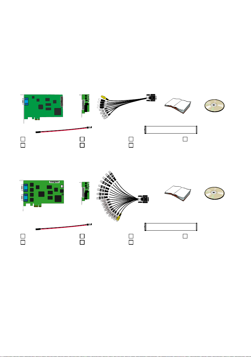
(1)
(2)
(3)
(4)
(5)
(6)
8
FC - 26P
(7)
(1) NV6120T
(3) 1 x AV cable
(5) Installation CD
(7) I/O cable
(2) I/O card
(4) Quick Guide
(6) 30cm Watchdog line
(1)
(2)
(3)
(4)
(5)
(6)
8
FC - 26P
(7)
(1) NV6240T
(3) AV cable
(5) Installation CD
(7) I/O cable
(2) I/O card
(4) Quick Guide
(6) 30cm Watchdog line
Chapter 1 Introduction
1.1 NV series
AVer DVR is a 32-bit PCI video capture card that works as a digital video surveillance system. It
enables you to capture true color images and real-time videos from 4 up to 16 camera inputs
simultaneously.
With the latest Motion Detection technology, you no longer need to monitor every single moment of the
day; the system automatically records and triggers an alarm when any movement is detected.
NV6120T Package
NV6120T package includes the following:
NV6240T Package
NV6240T package includes the following:
1
Page 14
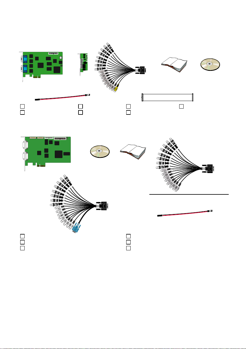
NV6480T Package
(1)
(2)
(3)
(4)
(5)
(6)
8
FC - 26P
(7)
(1) NV6480T
(3) 2 x AV cable
(5) Installation CD
(7) I/O cable
(2) I/O card
(4) Quick Guide
(6) 30cm Watchdog line
(1)
(2)
(3)
(4)
(5)
(6)
(1) NV8416T
(2) Installation CD
(3) Quick Installation Guide
(4) AV cable
(5) AV cable
(6) Watchdog line
NV6480T package includes the following:
NV8416T Package
NV8416T package includes the following:
2
Page 15

Software license CD
(4~32CH)
i
NXU8000 series provides 4~32 IP cameras connection that depends on the software
license user has purchased.
1.2 NXU8000 series
AVerTM NXU 8000 series is a software license that offers a way to install NVR surveillance application
in your computer or upgrading NV DVR server for extra IP camera connection that is authorized by the
license.
Package Contents
3
Page 16
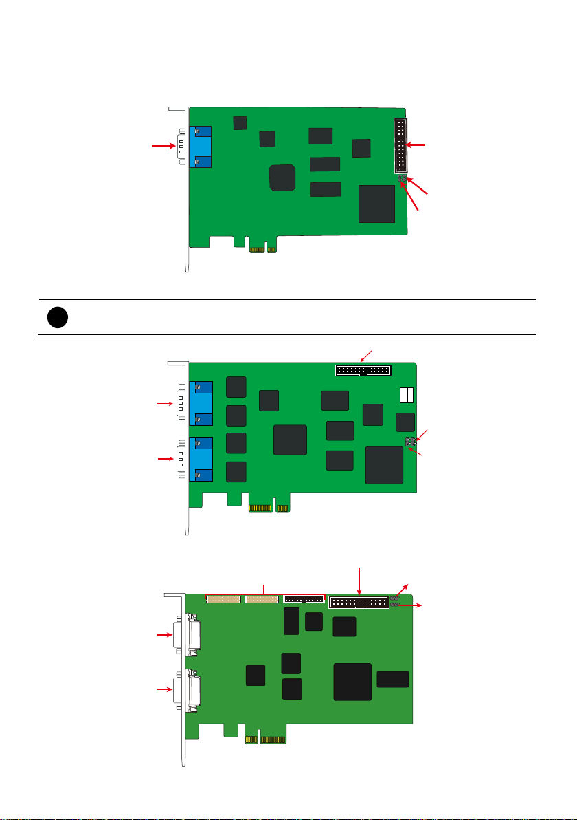
1.3 Card Parts
DVI AV In port
I/O connector
Reset pin
Watchdog pin
i
NV6240T card only has one DVI AV in port.
DVI AV In port
I/O connector
Reset pin
Watchdog pin
DVI AV In port
I/O connector
Reset pin
Watchdog pin
DVI AV In Port
DVI AV In Port
Connector for Display 21 card
NV6120T Card Parts
NV6000T series Card Parts (6420T/6480T)
NV8416T Card Parts
4
Page 17
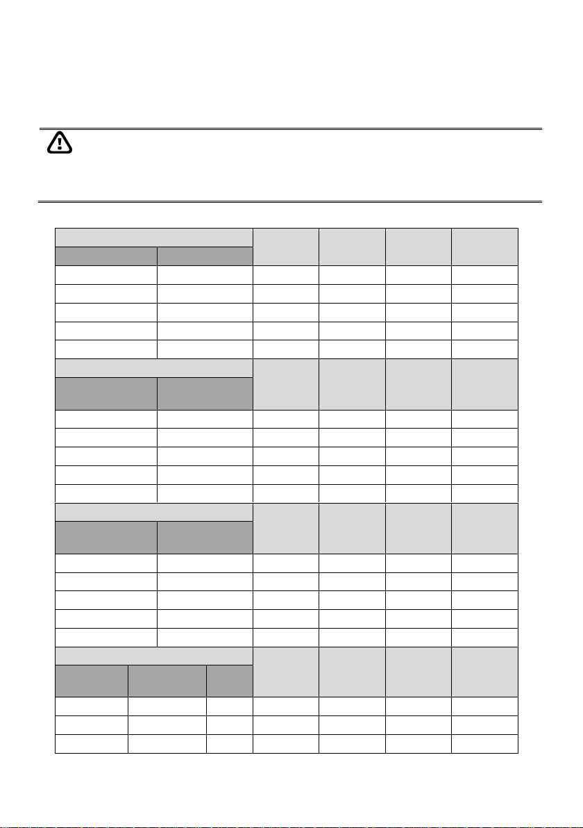
Product
Item
Recommended
NV6120T
CPU
1. Pentium® 4 3.2 GHz or higher
2. Dual core CPU is highly recommended
Mother Board
Intel G41/P43/X58/H55/P55/H61/H67/P67/Z68 chipset
RAM
1GB or higher
i
At least 3G RAM is required if you want to install up to 42 mega-pixel
IP cameras on your DVR system.
Graphic Card
32-bit high color SVGA graphics card with 128MB video
memory and DirectDraw® / YUV Rendering Capability
HDD
120GB or more
Ethernet
10/100/1000 Base-T Ethernet card
OS
Windows XP Professional(32bit) / 7 Professional (32bit)/ 7
Professional (64bit)
Others
PCI-Express x1, Sound card and speakers
For Windows 7, do the following setting in order to operate DVR normally.
- To disable User Account Control (UAC) before enter DVR system. To disable UAC,
please go to User Account setting in Control Panel to turn User Account Control off. If
UAC doesn’t disable, the DVR program will not allow to be installed.
- Adjust the Display mode to Basic mode.
- When formatting HDD, please select 64K allocation unit size.
Chapter 2 Hardware Installation
2.1 Minimum System Requirements
Verify if the computer meets the minimum system requirements.
5
Page 18

Product
Item
Recommended
NV6000T
(6240T/6480T)
CPU
3. Pentium® 4 3.2 GHz or higher
4. Dual core CPU is highly recommended
Mother Board
Intel G41/P43/X58/H55/P55/H61/H67/P67/Z68 chipset
RAM
1GB or higher
i
At least 3G RAM is required if you want to install up to 42 mega-pixel
IP cameras on your DVR system.
Graphic Card
32-bit high color SVGA graphics card with 128MB video
memory and DirectDraw® / YUV Rendering Capability
HDD
120GB or more
Ethernet
10/100/1000 Base-T Ethernet card
OS
Windows XP Professional(32bit) / 7 Professional (32bit)/ 7
Professional (64bit)
Others
PCI-Express x1, Sound card and speakers
For Windows 7, do the following setting in order to operate DVR normally.
- To disable User Account Control (UAC) before enter DVR system. To disable UAC,
please go to User Account setting in Control Panel to turn User Account Control off. If
UAC doesn’t disable, the DVR program will not allow to be installed.
- Adjust the Display mode to Basic mode.
- When formatting HDD, please select 64K allocation unit size.
6
Page 19

Product
Item
Recommended
NV6000T x 2
(32 Channel)
CPU
Intel Core 2 Duo E6600 2.4 GHz
Mother Board
Intel G41/P43/X58/H55/P55/H61/H67/P67/Z68 chipset
*Two PCI-E x 1 slots are required to install 32 channels
system
RAM
1GB or more
i
At least 3G RAM is required if you want to install up to 42 mega-pixel
IP cameras on your DVR system.
HDD
120GB or more
Ethernet
10/100/1000 Base-T Ethernet card
OS
Windows XP Professional(32bit) / 7 Professional (32bit)/ 7
Professional (64bit)
Others
Two PCI-Express x1, Sound card and speakers
For Windows 7, do the following setting in order to operate DVR normally.
- To disable User Account Control (UAC) before enter DVR system. To disable UAC,
please go to User Account setting in Control Panel to turn User Account Control off. If
UAC doesn’t disable, the DVR program will not allow to be installed.
- Adjust the Display mode to Basic mode.
- When formatting HDD, please select 64K allocation unit size.
7
Page 20
Product
Item
Recommended
NV8416T
CPU
1. Pentium® 4 3.2 GHz or higher
2. Dual core CPU is highly recommended
Mother Board
Intel G41/P43/X58/H55/P55/H61/H67/P67/Z68 chipset
RAM
1GB or more
i
At least 3G RAM is required if you want to install up to 42 mega-pixel
IP cameras on your DVR system.
HDD
120GB or more
Ethernet
10/100/1000 Base-T Ethernet card
OS
Windows XP Professional(32bit) / 7 Professional (32bit)/ 7
Professional (64bit)
Others
PCI-E x4 interface, Sound card and speakers
- CPU i7 and above 2G RAM is required for 32 channels real time recording.
- To disable User Account Control (UAC) before enter DVR system. To disable UAC,
please go to User Account setting in Control Panel to turn User Account Control off. If
UAC doesn’t disable, the DVR program will not allow to be installed.
- When formatting HDD, please select 64K allocation unit size.
Product
Item
Recommended
NXU8000 series
CPU
1. Pentium® 4 3.2 GHz or higher
2. Dual core CPU is highly recommended
Mother
Board
Intel G41/P43/X58/H55/P55/H61/H67/P67/Z68 chipset
RAM
1GB or higher
i
At least 3G RAM is required if you want to install up to 42
mega-pixel IP cameras on your DVR system.
HDD
120GB or more
Ethernet
10/100/1000 Base-T Ethernet card
OS
Windows XP Professional(32bit) / 7 Professional (32bit)/ 7
Professional (64bit)
Others
Sound card and speakers
- The NVR system can install NV software license is limited to 32 channels.
- NXU8000 series can be combined with NV DVR system and total channels are limited to
32 channels.
- When formatting HDD, please select 64K allocation unit size.
8
Page 21
Before installing the cards, the computer must be turned OFF, the power cable must be
UNPLUGGED and all other cables that are attached at the back of the computer must be
DISCONNECTED.
When installing multiple cards, it is important to arrange the cards in sequence so that the
cables would not tangle up.
Hardware Combinations
Camera
Input
Audio
Input
Sensor Input
Relay
Output
NV6480T Card
IO Card
1
0
16
16 0 0
1
1
16
16 4 4 2 0
32
32 0 0
2
1
32
32 4 4
2
2
32
32 8 8
Hardware Combinations
Camera
Input
Audio
Input
Sensor Input
Relay
Output
NV6240T Card
(8Channels)
IO Card
1 0 8 8 0 0 1 1 8 8 4
4
2
0
16
16 0 0
2
1
16
16 4 4 2 2
16
16 8 8
Hardware Combinations
Camera
Input
Audio
Input
Sensor Input
Relay
Output
NV6120T Card
(4Cannels)
IO Card
1 0 4 4 0
0
1 1 4 4 4
4
2 0 8 8 0 0 2 1 8 8 4
4
2 2 8 8 8
8
Hardware Combinations
Camera
Input
Audio
Input
Sensor Input
Relay
Output
NV6120T Card
(4Channels)
NV6240T card
(8Channels)
I/O
Card
1 1 0
12
12 0 0
1 1 1
12
12 4 4
1 1 2
12
12 8 8
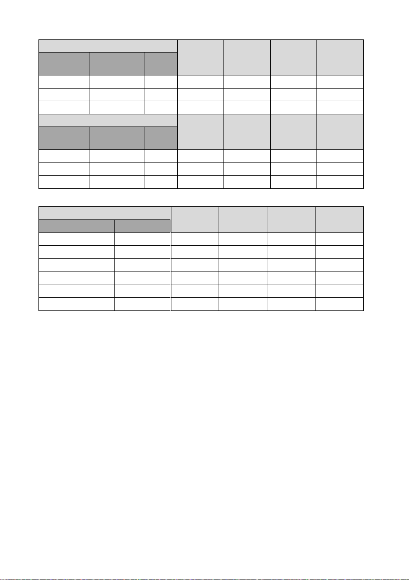
2.2 NV6120T/NV6240T/NV6480T/NV8416T Hardware Combinations
AVer NV DVR provides powerful surveillance functions and flexible hardware combinations. The table
shows the numbers of camera inputs, audio inputs, sensor inputs and relay outputs on different
hardware combinations.
NV6000T hardware combinations:
9
Page 22
Hardware Combinations
Camera
Input
Audio
Input
Sensor Input
Relay
Output
NV6120T Card
(4Channels)
NV6480T card
(8Channels)
I/O
Card
1 1 0
20
20 0 0
1 1 1
20
20 4 4
1 1 2
20
20 8 8
Hardware Combinations
Camera
Input
Audio
Input
Sensor Input
Relay
Output
NV6240T Card
(4Channels)
NV6480T card
(8Channels)
I/O
Card
1 1 0
24
24 0 0
1 1 1
24
24 4 4
1 1 2
24
24 8 8
NV8416T hardware combinations:
Hardware Combinations
Camera Input
Audio
Input
Sensor Input
Relay Output
NV8416T Card
IO Card 1 0
16
16 0 0
2
0
32
32 0 0 1 1
16
16 4 4
2
0
32
32 0 0
2
1
32
32 4 4
2
2
32
32 8 8
10
Page 23
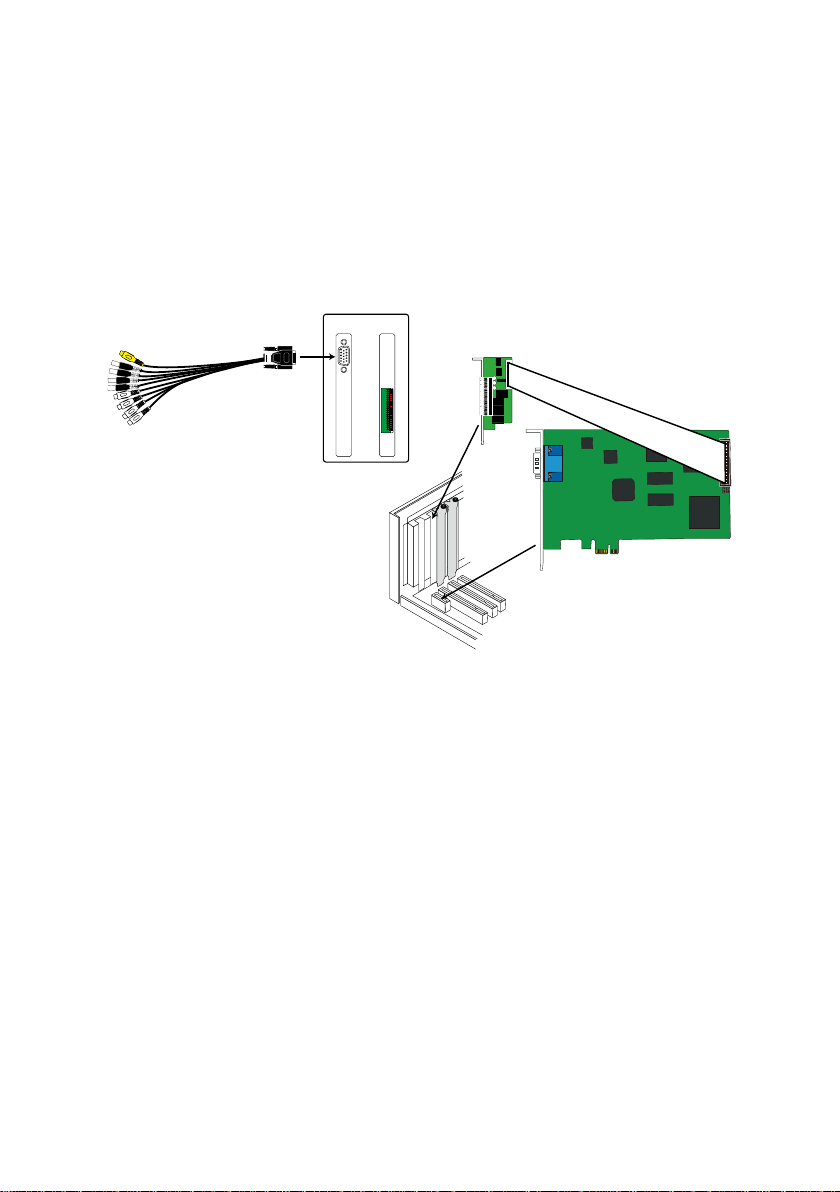
NV6120T Card
I/O card
AV connection cable
NV6120T
Card I/O card
2.3 NV6120T Hardware Installation
The NV6120T can support up to 8 cameras and 8 audio inputs.
2.3.1 Installing NV6120T and I/O card
1. Remove the PC case cover.
2. Remove 1 bracket that cover the PCI slot and 1 bracket that cover the PCI-Ex1 slot. Save the
screws.
3. Connect the NV6120T card and I/O card with the connection cable.
4. Press the cards into the PCI-Ex1 slots firmly.
5. Secure the card with the screws.
6. Connect the supplied AV connection cable to the DVI AV IN port.
11
Page 24
i
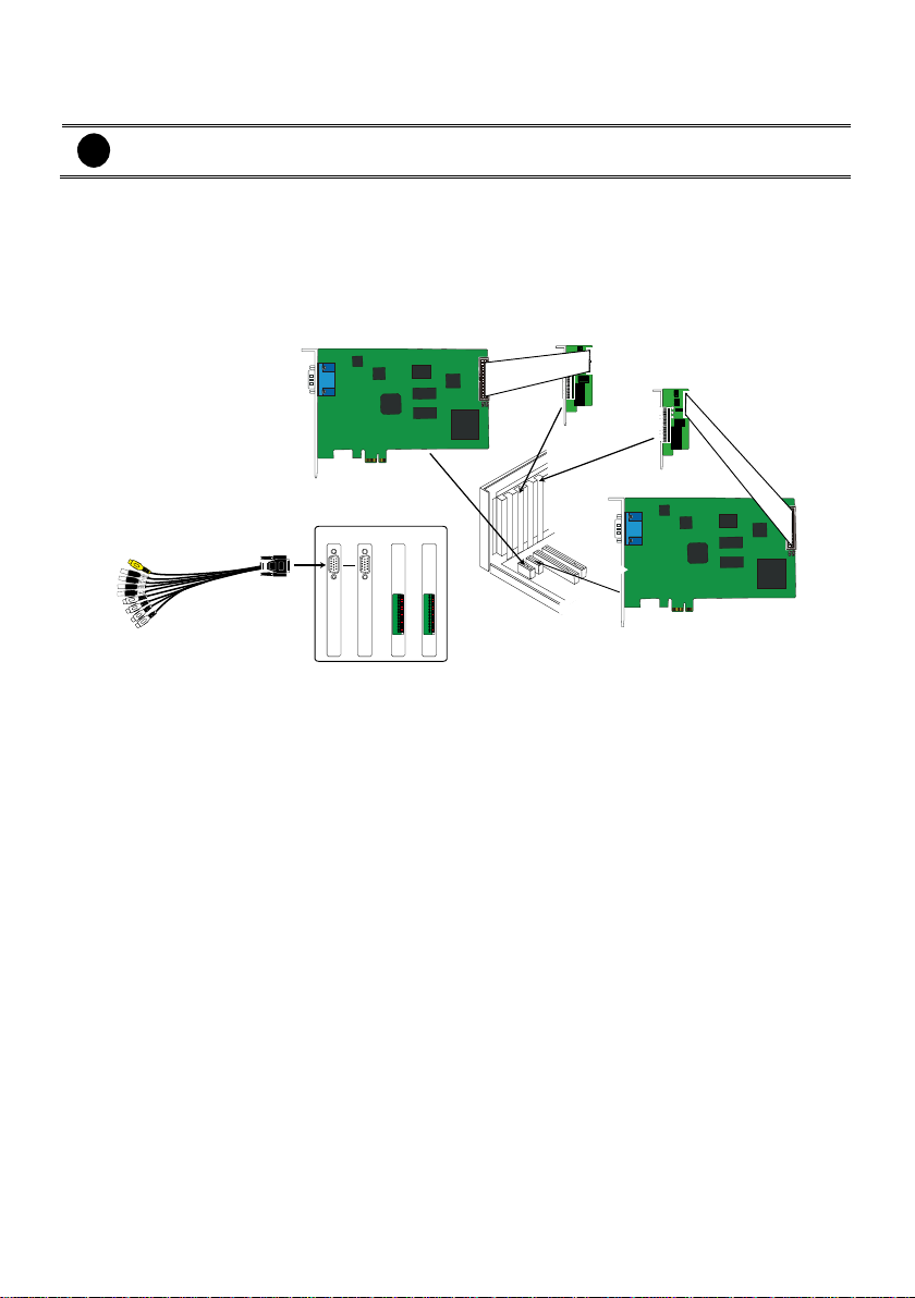
The PC motherboard needs to have 2 PCI-Ex1 slots for installing 2 NV6120T cards.
AV connection cable
NV6120T
Card
NV6120T
Card I/O cardI/O card
NV6120T Card
I/O card
I/O card
NV6120T Card
2.3.2 Installing (2) NV6120T and (2) I/O card
1. Remove the PC case cover.
2. Remove 2 brackets that cover the PCI slot and 2 brackets that cover the PCI-Ex1 slot. Save the
screws.
3. Connect the NV6120T cards and I/O cards with the connection cable.
4. Press the NV6120T cards into the PCI-Ex1 slots firmly and I/O card into the PCI slots firmly
5. Secure the card with the screws.
6. Connect the supplied AV connection cable to the DVI AV IN port.
12
Page 25
i
The PC motherboard needs to have 2 PCI-Ex1 slots for installing 2 NV6000T card.
NV6000T card
NV6000T card
NV 6000T NV 6000T
AV connection cable
AV connection cable
NV6000T card
I/O card
NV 6000T I/O card
AV connection cable
AV connection cable
2.4 NV6000T(6240T/6480T)Hardware Installation
The NV6000T can support up to 16 cameras and 8 audio inputs
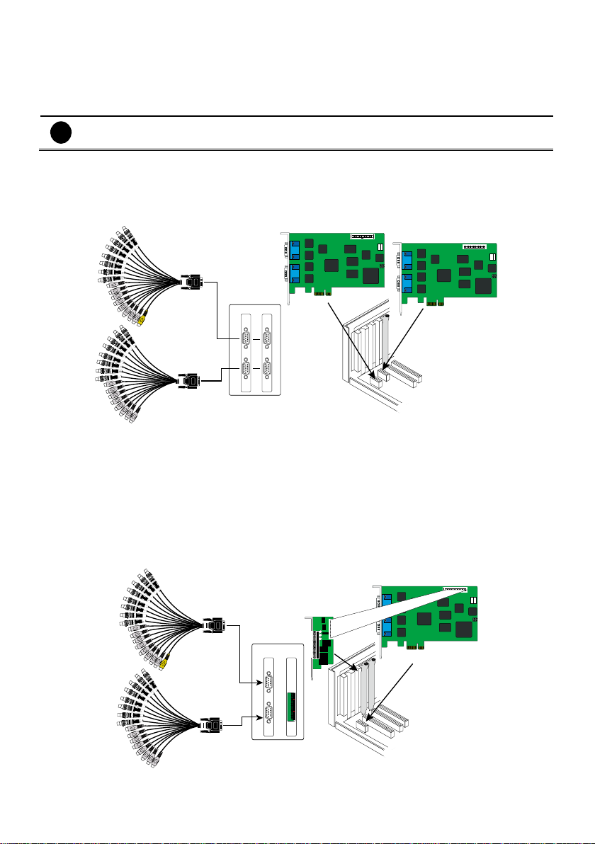
2.4.1 Installing (2) NV6000T card
1. Remove the PC case cover.
2. Remove 2 brackets that cover the PCI slots. Save the screws.
3. Press the cards into the PCI-Ex1 slot firmly.
4. Secure the card with the screws.
5. Connect the supplied AV connection cable to the DVI AV IN port.
2.4.2 Installing NV6000T and I/O card
1. Remove the PC case cover.
2. Remove 1 bracket that cover the PCI slot and 1 bracket that cover the PCI-Ex slot. Save the
screws.
3. Connect the NV6000T card and I/O card with the connection cable.
4. Press the cards into the PCI-Ex1 slots firmly.
5. Secure the card with the screws.
6. Connect the supplied AV connection cable to the DVI AV IN port.
13
Page 26
NV6000T card
NV6000T card
NV6000T NV6000T
AV connection cable
AV connection cable
I/O card
I/O card
I/O card I/O card
NV8416T card
NV 8416T
AV connection cable
AV connection cable
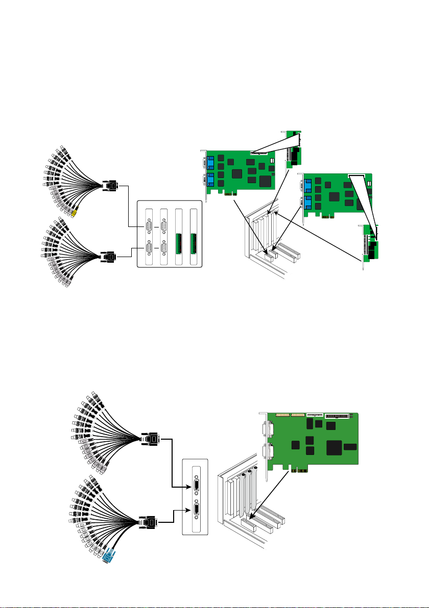
2.4.3 Installing (2) NV6000T and (2) I/O card (Optional)
1. Remove the PC case cover.
2. Remove 2 brackets that cover the PCI slot and 2 brackets that cover the PCI-Ex slot. Save the
screws.
3. Connect the NV6000T cards and I/O cards with the connection cable.
4. Press the NV6000T cards into the PCI-Ex1 slots firmly and I/O card into the PCI slots firmly
5. Secure the card with the screws.
6. Connect the supplied AV connection cable to the DVI AV IN port.
2.5 NV8416T Hardware Installation
2.5.1 Install NV8416T card
1. Remove the PC case cover.
2. Remove 1 bracket that covers the PC-Ex4I slot. Save the screws
3. Press the NV8416T card into the PCI-Ex4slot firmly.
4. Secure all the cards with the screws.
5. Connect the supplied AV connection cables to the AV IN ports.
14
Page 27
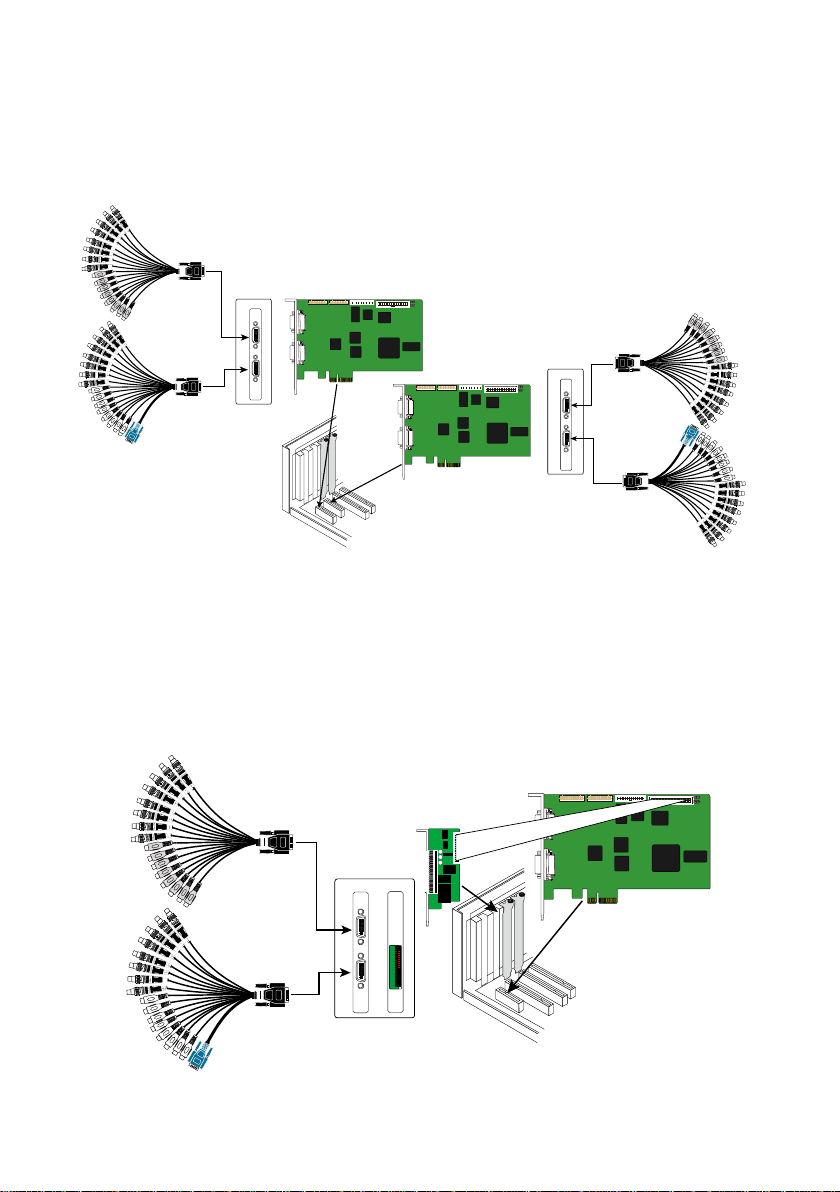
2.5.2 Install (2) NV8416T cards
NV8416T card
NV8416T card
NV8416T
AV connection cable
AV connection cable
NV8416T
AV connection cable
AV connection cable
NV8416T card
I/O card
NV 8416T I/O card
AV connection cable
AV connection cable
1. Remove the PC case cover.
2. Remove 2 brackets that cover the PCI-Ex4 slot. Save the screws
3. Press the NV8416T cards into the PCI-Ex4 slot firmly.
4. Secure all the cards with the screws.
5. Connect the supplied AV connection cables to the AV IN ports.
2.5.3 Install NV8416T card and I/O card (optional)
1. Remove the PC case cover.
2. Remove 1 bracket that cover the PC-Ex4I slot and 1 bracket that cover the PCI slot. Save the
screws
3. Connect the NV8416T card and I/O card with the connection cable.
4. Press the NV8416T card into the PCI-Ex4 slot and I/O card into the PCI slot firmly.
5. Secure all the cards with the screws.
6. Connect the supplied AV connection cables to the AV IN ports.
15
Page 28
NV8416T card
NV8416T card
NV8416T
AV connection cable
AV connection cable
NV8416T
AV connection cable
AV connection cable
I/O card
I/O card
I/O card
I/O card
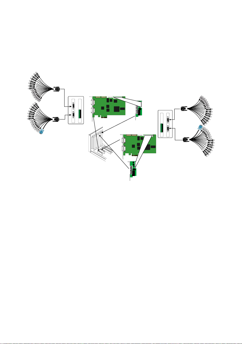
2.5.4 Install (2) NV8416T card and (2) I/O card (optional)
1. Remove the PC case cover.
2. Remove 2 brackets that cover the PC-Ex4I slot and 2 brackets that cover the PCI slot. Save the
screws
3. Connect the NV8416T cards and I/O cards with the connection cable.
4. Press the NV8416T cards into the PCI-Ex4 slot and I/O cards into the PCI slot firmly.
5. Secure all the cards with the screws.
6. Connect the supplied AV connection cables to the AV IN ports.
16
Page 29
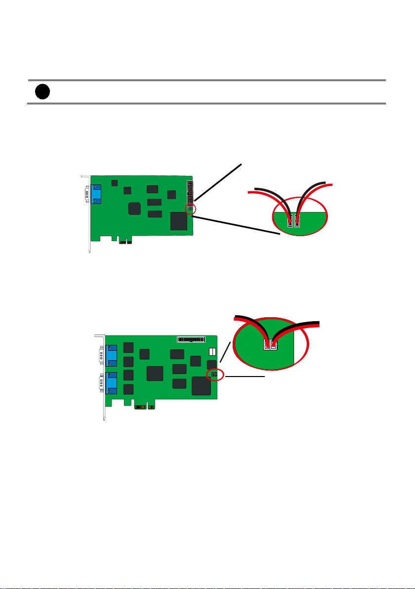
i
If more than one NV6120T/NV6000T (6240T/6480T)/NV8416T card is installed, connect
the watchdog line at last card.
NV6120T
Reset SW lead
Watchdog line
NV6000T
Reset SW lead
Watchdog line
2.5.5 Connecting the Watchdog line
The DVR program constantly monitors its operation. Connecting the NV6120T/NV6000T
(6240T/6480T) /NV8416T to the motherboard reset switch panel, enables the unit to restart
automatically and reset the system when an error has been detected.
2.5.6 Connecting the Watchdog line to NV6120T
1. Look for the labeled RESET SW switch lead and connect it to the NV6120T card reset pin.
2. Connect the supplied Watchdog line to the NV6120T card watchdog pin and the other end to the
motherboard RESET SW panel. If you are not sure, please refer to the motherboard user manual.
3. You may now replace back the PC cover and connect all the cables.
2.5.7 Connecting the Watchdog line to NV6000T
4. Look for the labeled RESET SW switch lead and connect it to the NV6000T card reset pin.
5. Connect the supplied Watchdog line to the NV6000T card watchdog pin and the other end to the
motherboard RESET SW panel. If you are not sure, please refer to the motherboard user manual.
6. You may now replace back the PC cover and connect all the cables.
17
Page 30

NV8416T
Reset SW lead
Watchdog line
2.5.8 Connecting the Watchdog line to NV8416T
1. Look for the labeled RESET SW switch lead and connect it to the NV8416T card reset pin.
2. Connect the supplied Watchdog line to the NV8416T card watchdog pin and the other end to the
motherboard RESET SW panel. If you are not sure, please refer to the motherboard user manual.
3. You may now replace back the PC cover and connect all the cables.
18
Page 31

i
The DVR system supports both analog and IP camera channel for TV output.
2.6 Connecting the Cameras, a TV and Audio device
2.6.1 Connecting the Cameras, a TV and Audio devices to NV6120T
1. Use the supplied AV connection cable and connect it to the D-type AV IN port of NV6120T card
(see NV6120T card parts).
2. Connect the cameras to the BNC video connectors and audio devices to the RCA audio
connectors. Just follow the order basing on the marked sequence.
3. Connect one end of the RCA video cable (not supplied) to the TV OUT port of NV6000T card and
the other end to the TV video input port. If you are not sure, please refer to the TV user manual.
19
Page 32

NV6000T
MIC 3
MIC 2
MIC 4
MIC 5
MIC 6
MIC 7
MIC 8
MIC 1
RCA cable
Television
AV connection cable
MIC 3
MIC 2
MIC 4
MIC 5
MIC 6
MIC 7
MIC 8
MIC 1
i
The DVR system supports both analog and IP camera channel for TV output.
2.6.2 Connecting the Cameras, a TV and Audio devices to NV6000T
4. Use the supplied AV connection cable and connect it to the D-type AV IN port of NV6000T card
(see NV6000T card parts).
5. Connect the cameras to the BNC video connectors and audio devices to the RCA audio
connectors. Just follow the order basing on the marked sequence.
6. Connect one end of the RCA video cable (not supplied) to the TV OUT port of NV6000T card and
the other end to the TV video input port. If you are not sure, please refer to the TV user manual.
20
Page 33

NV8416T
Camera 5 Camera 6 Camera 7 Camera 8Camera 2 Camera 3Camera 1 Camera 4
MIC 3
MIC 2
MIC 4
MIC 5
MIC 6
MIC 7
MIC 8
MIC 1
AV connection cable
Camera 5 Camera 6 Camera 7 Camera 8Camera 2 Camera 3Camera 1 Camera 4
MIC 3
MIC 2
MIC 4
MIC 5
MIC 6
MIC 7
MIC 8
MIC 1
AV connection cable
LCD Monitor
2.6.3 Connecting the Cameras, a LCD Monitor, and Audio devices to NV8416T
1. Use the supplied AV connection cable and connect it to the DVI AV IN port of NV8416T daughter
card (see NV8416T card parts).
2. Connect the cameras to the BNC video connectors and audio devices to the RCA audio
connectors. Just follow the order basing on the marked sequence.
3. Connect the LCD Monitor to VGA cable.
21
Page 34

2.7 Dual Monitors Setup
The NV DVR system Supports Single and Dual monitor displays. When using dual monitors, the Emap
and Playback function will be display on the second monitor.
The Video configuration is different for each different VGA chipsets. Please follow the steps below to
setup the dual monitors display.
2.7.1 Graphic card with ATi chipset
1. Enter the ATI Catalyst Control Center, user can click the short-cut or right click on the screen.
2. There are two modes to select ─ Basic and Advanced.
3. If user selected Basic mode, press the Quick Settings tab. Then select the Select a different
desktop mode and click Go.
22
Page 35

4. Select the Extended Desktop and then click Finish.
5. If user selected the Advanced mode, click the View button.
6. In Display Manager, right click on the second Display on the right side and select Extend Main
onto monitor.
7. Adjust each monitor resolution to 1024x768, 1440x900, 1680x1050, 1920x1200 or 1920x1080.
23
Page 36

2.7.2 Graphic card with NVIDIA chipset
1. Click the NVIDIA nView, and select the Dualview mode.
2. Adjust each monitor resolution to 1024x768, 1440x900, 1680x1050, 1920x1200 or 1920x1080
3. To review if the display mode is correct, you can check the task bar. The task bar will show on the
first monitor only.
Monitor 1 Monitor 2
24
Page 37

2019181716151413121110987654321
Pin #
Definition
Pin #
Definition
1
Sensor input signal 1+
11
Relay Normal Close 1
2
Sensor output signal 1(GND)
12
Relay Common 2
3
Sensor input signal 2+
13
Relay Normal Open 2
4
Sensor output signal 2(GND)
14
Relay Normal Close 2
5
Sensor input signal 3+
15
Relay Common 3
6
Sensor output signal 3(GND)
16
Relay Normal Open 3
7
Sensor input signal 4+
17
Relay Normal Close 3
8
Sensor output signal 4(GND)
18
Relay Common 4
9
Relay Common 1
19
Relay Normal Open 4
10
Relay Normal Open 1
20
Relay Normal Close 4
2.8 Sensor and Relay pinhole allocation on I/O Card
2.8.1 NV6120T/NV6240T/NV6480T/NV8416T
The I/O Audio card enables you to connect (4) sensor inputs and (4) relay outputs. Just connect the
external sensor and relay pin directly to the NV6120T/NV6240T/NV6480T//NV8416T I/O card pinhole.
Check the table below and locate which pinhole is assigned to sensor input and relay output.
The signal from the sensor (i.e., infrared sensors, smoke detectors, proximity sensors, door sensors,
etc.) is being transmitted to the I/O card and this triggers the system to respond and send signal to
relay device (i.e., alarm, telephone etc).
25
Page 38

Absolute Maximum Ratings
(Ta=25°C)
Parameter
Symbol
Rating
Unit
Input
Forward Current
IF
50
mA
Reverse Voltage
VR 6 V
Power Dissipation
P
70
mW
Electrical/Optical Characteristics
(Ta=25°C)
Parameter
Symbol
Min
Typ.
Max.
Unit
Conditions
Input
Forward Current
VF - 1.2
1.4 V IF=20mA
Reverse Voltage
IR - -
10 A VR=4V
Terminal Capacitance
Ct - 30
250
pF
V=o, f=1KHz
Parameter
Symbol
Min
Typ.
Max.
Unit
Conditions
Output
Collector Dark Current
I
CEO
- -
100
nA
VCE=20V
Collector-Emitter
Breakdown Voltage
BV
CEO
35 - - V IC=0.1mA
Emitter-Collector
Breakdown Voltage
BV
ECO
6 - - V
IE=10 A
Transfer Characteristics
*Current Transfer
Ratio
CTR
50 - 600
%
IF=5mA, VCE=5V RBE=
Collector Current
IC
2.5 - 30
mA
Collector-Emitter
Breakdown Voltage
V
CE(sat)
- 0.1
0.2 V IF=20mA, IC=1mA
Isolation Resistance
R
ISO
5 x 10¹⁰
1011 -
DC500V, 40-60% R.H.
Floating Capacitance
Cf - 0.6
1.0
pF
V=0, f=1MHz
Cut-off Frequency
fc - 80 KHz
VCE=5V, IC=2mA
RL=100, -3dB
Response Time (Rise)
tr - 4
18
s
VCE=2V, IC=2mA
RL=100
Response Time (Fall)
tf - 3
18
s
*CTR=
IC
100%
IF
Surge strength
:1500 VAC
Nominal power
: 200mw ~ 360mw
Operating power
: 110mw ~ 200mw
Coil Nominal Voltage
(VDC)
Coil Resistance
10%
Pick-up Voltage
(VDC)
Drop-Out Voltage
(VDC)
Nominal Current
(mA)
5
125
3.75
0.5
40
Contact Arrangement
1 Form C (SPDT)
max. Switch Power
max. Switch voltage
max. Switch current
125VA 60W
125VAC 30VDC
1A
Contact Resistance
≤ 100mΩ
Resistive Load
1A/125VAC
1A/30VDC
2.9 The Sensor input and Relay output Specifications
You may use the sensor input and relay output specifications table below for your reference.
A. Sensor Input Specification
B. Relay Output Specification
C. COIL RATINGS (at 20 oC )
* Max Continuous Voltage at 20oC : 110% of Coil Nominal Voltage
D. CONTACT RATINGS
26
Page 39

RS232 cable
i
For detail of POS installation, please refer to POS Quick Guide.
2.10 Connecting POS (Point of Sales)
AVer DVR can be integrated with POS system equipment. Connecting the POS equipment to AVer
DVR system thru RS232 connection, enables you to view, record and keep track of the items that were
sold. You may also select the camera on where to display all the data.
To connect, locate the RS232 port of the POS equipment and PC. Use an RS232 cable (not supplied)
to make the connection.
27
Page 40

The CD-Key is permitted for use on a single computer. It is prohibited to use the CD-key
on more than one computer. Once detected, this would cause a system conflict and some
of the features might fail to work on both PC.
Before installing the software, make sure that the Windows OS patches and the video
graphic card driver are UPDATED.
If you have an old version of the DVR software installed in your PC, the old copy must be
removed. To remove, click Start >Settings > Control Panel and then double click
Add/Remove Programs. In Add/Remove Programs list, select NV DVR and then click
Remove.
We HIGHLY RECOMMEND having three (3) separate drives for the main system (OS and
DVR software), storage and backup. The ideal hard disk size for the main drive is 20GB.
As for the storage and backup, at least 60GB each. The hard drives format must be in
NTFS. This way we can maintain an optimized system for your security.
i
To ensure getting the latest copy of DVR software, go and download the updated version
from the following site:
Worldwide :
H http://surveillance.aver.com/download-center
US/CANADA:
H http://www.averusa.com/surveillance/download.aspx
Chapter 3 Software Installation
This chapter describes how to install the DVR software, drivers, install NV software license (NXU8000
series), and upgrade the DVR/NVR by software license.
28
Page 41

Upon turning the computer on, the system automatically detects the newly installed
hardware. When the Found New Hardware dialog box appears, IGNORE it.
Remember :
It is important to install the NV DVR software first, before installing the
drivers.
3.1 Installing NV DVR Software and Drivers in Windows XP/7
Please follow the below steps to install NV application:
1. Place the installation CD into the CD-ROM drive then click Install Surveillance System. Then,
follow the on-screen instructions.
2. When product select dialog appears, mark the NV card that you have purchased.
3. Accept the license agreement to continue the installation. If you do not agree the license
agreement, the installation will be canceled.
4. Enter your company name and the CD-Key that is located on the back of installation CD sleeve.
5. Then, click OK to complete the installation.
6. You may now run the NV DVR program. To run the application, click on your PC desktop or
click Start > Programs > DVR > NV6000 or NV8000 (it displays the NV capture card that user has
installed).
29
Page 42

DO NOT install Software License to multiple PCs, it won’t work if the license key has been
found on multiple PCs.
3.2 Installing NV Software License(NXU8000 series)
3.2.1 For New Installation
If the system hasn’t installed any DVR software and NV card, please follow the below steps to install:
1. Place the Software License CD into CD-ROM drive on your PC.
2. Then, click Install Surveillance System and follow the on-screen instructions.
3. When product select dialog appears, mark the NXU selection to install.
4. Accept the agreement license to continue the installation. If you do not agree the license
agreement, the installation will be cancel.
5. Enter your company name and the CD-Key that is located on the back of installation CD sleeve.
6. Then, click OK to complete the installation.
7. After completing the installation, you may now run the application program. To run the application,
click on your PC desktop or click Start > Programs > DVR > NXU8000 series.
8. Before starting to connect IP camera, user needs to enter the activation key to active the IP
camera channels. To enter activation key, user needs to do the License Upgrade procedure. There
are 2 ways to enter the license upgrade process:
a. Press F1 to call out the System Information dialog, then, click the License Upgrade button.
30
Page 43

Click Yes to
continue it.
1
2 3 4
Click OK to save the
DVR information file to
selected location.
Enter the CD-Key and
click Export button.
b. Click power button ( ) and click About button. The Product Information dialog is shown up
and click License Upgrade button.
9. Next, DVR System would ask user to enter the activation key (License.bin). If user didn’t get the
activation key (License.bin),then, click “ No” and input CD-Key of NV DVR/NVR that user has
purchased. And, click Export button to export a DVR information file (computerinfo.bin) and give
to your distributor. Your distributor will generate an activation key based on the file
(computerinfo.bin) that user has provided.
31
Page 44

After upgrading, the IPCam license
is appeared and display how many
channel license that user has
purchased.
10. After getting the activation key (License.bin), click “Yes” and import your activation key
(License.bin).
11. Then, DVR/NVR system will need to restart to take effect.
12. After DVR/NVR system restarting, user can press F1 to check IP camera license information to
make sure the upgrading is successful.
32
Page 45

3.2.2 For Upgrading Installation
To upgrade the extra IP camera channels for existing NVR/DVR system, please follow the below steps
to upgrade:
1. Run the NVR/DVR application.
2. There are 2 ways to enter the license upgrade process:
a. Press F1 to call out the System Information dialog, then, click the License Upgrade button.
b. Click power button ( ) and click About button. The Product Information dialog is shown up
and click License Upgrade button.
33
Page 46

Click Yes to
continue it.
1 2 3
4
Click OK to save the
DVR information file to
selected location.
Enter the CD-Key and
click Export button.
3. Next, DVR System would ask user to enter the activation key (License.bin). If user didn’t get the
activation key (License.bin),then, click “ No” and input CD-Key of NV DVR/NVR that user has
purchased. And, click Export button to export a DVR information file (computerinfo.bin) and give
to your distributor. Your distributor will generate an activation key based on the file
(computerinfo.bin) that user has provided.
34
Page 47

After upgrading, the IPCam license
is appeared and display how many
channel license that user has
purchased.
4. After getting the activation key (License.bin), click “Yes” and import your activation key
(License.bin).
5. Then, DVR/NVR system will need to restart to take effect.
6. After DVR/NVR system restarting, user can press F1 to check IP camera license information to
make sure the upgrading is successful.
35
Page 48

i
Please make sure the cursor is located on User ID or Password column if user has call out
virtual keyboard for entering ID and password.
Chapter 4 Using the DVR Software
4.1 Running the DVR Software
To run the application, double-click on your PC desktop.
For security purpose, some of the features would require you to enter User ID and Password before it
can be accessed. When the Authorization dialog box appears, key in your User ID and Password. (If
this is the first time, enter the one you have registered when installing the software.)
4.2 Using the Virtual Keyboard
If the keyboard is not available, you may use the Virtual Keyboard. Just click to show the virtual
keyboard. For uppercase and lowercase, click shift button.
36
Page 49

i
User can re-do the Setup Wizard anytime.
4.3 System Setup Wizard
The Setup Wizard can guide the user to complete the basic but important setting of DVR system.
After login the DVR/NVR system, click Setup > Setup Wizard to start wizard.
37
Page 50

4.3.1 System Setting Wizard
In System Setting step, select the language of DVR system and interface, current time zone of DVR is
located, setup network time synchronization, and select video standard of DVR system.
1. Language: Customize the language for the DVR system, interface, and tool tips based on the
selected language. The default the language is in English.
2. Time Zone: Select the time zone, time, year, and date of DVR is located to setup correct DVR
time.
3. Network Time Synchronization: Adjust the DVR system time same as network time server.
Enter the Time Server IP address or domain name. Select Automatic Synchronize time to set
automatic synchronize time on a daily basis. To adjust time manually, click Sync Now button to
adjust time right away.
4. Video Standard: Change and select the proper video standard according to your camera video
system. If the video system setting is wrong, the video would appear abnormally.
5. Click Next to go to next wizard section.
38
Page 51

i
Do Not assign the DVR to 1.0.0.0 network segment. It will cause the DVR cannot
access to Internet due to the un-recognize to 1.0.0.0 IP segment.
i
The DDNS setting is not required to setup if user hasn’t apply your domain name yet.
The green light
indicates the LAN
port is connected
with Ethernet cable.
4.3.2 Network Setting Wizard
Setup the IP address of DVR and configure the DDNS. After completed all configuration, click Next to
save the setting and go to next wizard setting.
1. LAN: Select IP address mode -- DHCP or Static IP.
DHCP: To use DHCP server assigning DVR server an IP address.
Static IP: Assign a fixed IP address for DVR server
- IP ADDRESS: Assign a constant IP address which a real IP addresses give from ISP to
DVR system.
- Mask: It is a bitmask used to identify the sub network and how many bits provide room for
host addresses. Enter the subnet mask of the IP address which user has assigned to DVR
system.
- GATEWAY: A network device act as a passageway to internet. Enter the network gateway
IP address
- DNS: Domain Name Server translates domain names (such as www.abb.com.tw) to IP
addresses. Enter the IP address of DNS if it is available.
2. DDNS setting: To use this feature, go to http://ddns.avers.com.tw or http://dyndns.org and
register.
39
Page 52

dyndns.org
- Domain Name: The user has applied on website www.dyndns.org.
- ID: The account ID that user has created on website www.dyndns.org.
- Password: The password that user has assigned on website dyndns.org.
dyndns.org
ddns.avers.com.tw
- Domain Name: The domain name that user has applied on website ddns.avers.com.tw.
- CD-Key: The CD-Key is located on back panel of DVR unit.
- Password: The password that user has assigned on website ddns.avers.com.tw.
ddns.avers.com.tw
40
Page 53

i
One of CD-Key allows user to register two domain names. One of domain name can be
used by Dispatch serve.
i
- Note that Host Name and Domain Name (avers.com) are the replacement for Internet
address while a remote client tends to search a dynamic server.
- Host Name column supports alphabet letters and number only. The maximum character
is 15.
- The password maximum character is 12.
Register the Domain Name on http://ddns.avers.com.tw
1. User Login: Browse the website ddns.avers.com.tw with Microsoft IE or Netscape
Navigator to access the following dialog.
- First input CD-Key number and select the product name.
- Then click OK to login or Reset to clear the previous input.
2. User Information: Please provide the following user information, Host Name (user can
choose any name he/she likes except the one in conflict with other users), Password, E-
mail, Company, and Country. And then, click OK to complete the domain name
registration.
Register the Domain Name on http://www.dyndns.com
1. Open the browser on your PC and enter the URL http://www.dyndns.com
2. Follow the DyDNS’s instruction on website to apply the free domain name.
41
Page 54

4.3.3 Display Setting Wizard
Set monitor resolution and frequency. The DVR system support dual monitor and user need to set a
primary monitor when using dual monitor mode. The preview UI is displayed on primary monitor
(Monitor 1) and the Monitor 1 sign is displayed at left-upper corner on preview UI screen. The
playback UI and Eamp UI are displayed on monitor 2 and Monitor 2 sign is displayed at left-upper
corner on screen.
Select the Resolution and Frequency from drop-down list and click Next to save the setting and go
to next wizard setting.
42
Page 55

4.3.4 Storage Setting Wizard
To create partition, format the hard disk and select storage path for saving recording data. Also, user
can setup iSCSI for an extra storage capability if user has iSCSI server on your LAN network.
HDD Setting: To create and format hard disk partition, delete a partition, and formatting the hard
disk.
Create a partition
1. Select the hard disk from Hard Disk Information table.
43
Page 56

2. Click on the hard disk is in Volume Information table and click Create volume to set the
size of partition.
3. User can enter the partition size or scroll the bar to adjust the size. Then, click OK to create
and format the partition. The created and formatted partition will list in Volume Information
table.
44
Page 57

4. Each partition is assigned a letter as a volume ID. When user select a storage path, please
remember the volume ID match to which partition. To select storage path, click Next to go
to Storage Setting page.
5. To create another partition, repeat the above steps.
45
Page 58

Release the partition: User can delete the partition. When the partition has been deleted, all
data save in partition will be erased
1. In Volume Information table, click Release icon ( ) of the partition that user wants to
delete it.
2. The DVR system will delete the partition and all data will be erased.
46
Page 59

Format the hard disk: To format a hard disk or a partition. All data on the hard disk or
partition will be erased.
1. Select the hard disk in Hard Disk Information table and select the partition or hard disk that
want to be format in Volume Information table.
2. Then, the Format button will show and click Format button to format it.
47
Page 60

iSCSI: To connect the iSCSI server that user has on LAN network.
1. Click iSCSI button.
2. Enter the IP address or DNS name of the iSCSI server and click Quick Connect to make a
connection to iSCSI server. After connected, user can set the iSCSI server as a storage path.
48
Page 61

Storage Path
Set the directory on where to save the data. When there is not enough free space to record one hour
data, the system automatically replaces the oldest data. In case you have more than one storage path,
the system automatically saves the data to the next storage path.
1. Click button to select a storage path.
49
Page 62

2. In File Browser window, select the hard disk drive from Current Drive drop-down list.
3. Then, click New Folder icon to create a new folder for saving recording data.
4. Click OK to complete it.
5. A storage path will display in Storage Path table. To add another storage path, repeat above steps.
To delete a storage path, select the path and click
button
50
Page 63

6. After completing Storage setting, click Exit button and select Yes to save and exit the Setup
Wizard. If user wants to modify some of setting, select No will back to Setup Wizard.
51
Page 64

4.4 Familiarizing the Buttons in Preview/Advanced Mode
DVR system now supports 1024x768, 1440x900, 1680x1050, 1920x1200 or 1920x1080 display
resolution.
Preview mode in width screen display
Preview mode in regular screen display
52
Page 65

Name
Function
(1) Exit
Call up the Logout dialog box.
In the logout dialog box, you may do the following:
- Click Exit to close the DVR program.
- Click Reboot to restart DVR system.
- Click Login to sign-in in different account.
- Click About to update patch or find about the software info.
To update the patch file, Click Update and select the patch file
location – Local Machine or Server Download. And then, select
Update type – Main program or IP camera.
To upgrade software license, click License Upgrade. Detail refers to
Chapter 3.
- Click Minimize to reduce the DVR to taskbar button.
- Click Compact to switch to compact mode (see Chapter 4.4).
- Click Guest to switch to the guest mode. In guest mode, the functions
are limited to preview function only. For complete functions of DVR,
please login as an administrator.
- Click Cancel to exit Logout dialog box.
53
Page 66

Name
Function
(2) Split Screen
Mode
Select from 7 different split screen types to view all the camera, or one
camera over the other or alongside on a single screen. It also allows you to
switch and view different camera number.
i
- If there are only 4 cameras, you won’t be able to switch to 9, 16, 13, and 32 split screen
mode.
- The DVR system will save the current operating mode (split screen mode, auto scan, full
screen, and compact mode status) when shutdown DVR application and apply the mode
status for next login.
- When you are in single screen mode, Right-click and Drag a square on the area you
want to enlarge. Using left button of mouse click on the enlarge screen area and user
can move the screen for viewing. Right-click on screen again will back to normal view.
- In multiple-screen mode, user can re-arrange the channels’ display order. Right click
the video screen of the channel and Drag on where you want to relocate it. However, the
changed display order of channel only applies in preview mode and wouldn’t apply in
playback.
(3) Record
Start/stop video recording. The authorize password is required for disabling
the record function. The authorization dialog will show the warning message
to inform the user for stop recording.
i
Please make sure the cursor is located on Password column if user
has call out virtual keyboard for entering ID and password.
(4) Emap
Display the map in each area, and the location of camera/ sensor/ relay and
the warning (see also Chapter 4.7).
(5) Network
Enable/disable remote system access. This feature allows you to access
DVR server from a remote location via internet connection (see also Chapter
8). The authorize password is required for disabling the network function.
The authorization dialog will show the warning message to inform the user
for disabling network.
i
Please make sure the cursor is located on Password column if user
has call out virtual keyboard for entering ID and password.
54
Page 67

Name
Function
(6) Setup
Configure the system settings (see also Chapter 5).
(7) PTZ
Access PTZ control panel. Beside PTZ camera, DVR system also support
mega pixel IP PTZ camera (see also Chapter 4.6).
(8) Preview
Switch to Preview/Advanced mode. This allows you to view live camera
display. Press ctrl + F can freeze the live preview video screen. And then,
click Snapshot can save the freeze video screen.
(9) Playback
Switch to Playback mode. This allows you to view the recorded video file(see
Chapter 4.5).
(10) Status Bar
Display the current date, time and hard disk free space.
(11) Camera
Group Tree
To view the user defined channel group tree(see also Chapter 5.2.4). Click +
of group to extend group and drag the camera to surveillance screen to view.
Click + of camera to view the camera information.
(12) Camera ID
Show the number of cameras that are being viewed. When you are in single
screen mode, click the camera ID number to switch and view other camera.
55
Page 68

Name
Function
(13) iPOS Live
To view the real
time iPOS data
of channels.
Click the
iPOSLive to call
out the real time
iPOS data
window.
User can move
the channel of
iPOS window
apart to proper
position. If user
didn’t enable the
multi-channel of
iPOSLive( see
also POS
Adavanced
Setting in 5.1.1),
and then, user
only can view
one channel each time.
To switch to different channel, click Select Camera drop down list to select
the channel. To tempore stop iPOS data coming, click Freeze. To un-freeze,
click Transaction.
(14) Snapshot
Capture and save the screen shot either in *.jpg or *.bmp format.
(15) Event log
Show the record of activities that take place in the system (also see Chapter
4.3.1).
(16) AutoScan
Start/Stop video screen cycle switch (see also Chapter5.1 #6).
56
Page 69

Name
Function
(17) Full screen
Use the entire area of the screen to only display the video. To return, press
the right button of the mouse or ESC on the keyboard or click the arrow icon.
When DVR in full screen mode, each channel will display current date and
time.
When you switch to full screen in multiple-screen mode, Left click to toggle to
only display one of the video in the multiple-screen mode or all.
(18) Alarm
Alert and display warning info. Only Administrator-level can reset and turn
on, off and trigger the Sensor and Relay by right-clicking the item in the
Sensor and Relay list.
(19) Live Playback
button
When live playback function has enabled in Miscellaneous at System
Setting, the live playback icon is appeared on Preview UI while recording
status. Click to playback the recorded file instantly in preview mode.
When the channel is in live playback mode, the icon is . Move the
mouse to the bottom of the live playback channel, the playback tool bar
( ) will show up. Using the playback tool bar to
control the playback. Total 4 channels can be live playback at the same time.
Click to back to
normal display view.
57
Page 70

Name
Function
(20) Volume
Adjust the sound volume.
(21) On Screen
Keyboard
If the keyboard is not available, you may use the Virtual Keyboard.
(22) De-interlace
To enhance the video quality. Set the de-interlace mode to #1, if you are
capturing motionless picture and #2, if it captures lots of movement.
i
IP camera doesn’t support de-interlace.
(23) Turbo
To improve the smoothness of live video. Turbo button is disabled
( )
in
default. When turbo button is enabled or disabled that applies to whole DVR
system, not the specific channel. When restart or shutdown DVR/NVR
system, the current turbo status won’t be saved by DVR/NVR system.
58
Page 71

i
- DVR system now supports HDD failure pre-detection mechanism called HDD S.M.A.R.T.
function. Once when DVR system has detected the HDD failure possibility, an event log
will be occurred and user can check it in Event Log Viewer window.
- The HDD S.M.A.R.T. function accurate is approximately about 60%.
- The HDD warming event log will issue once a day.
i
HDD S.M.A.R.T. warning messages’ description are as following:
- HDD warning (Low risk): abnormal situations are occurred frequently but hard disk can
recovery by itself.
- HDD warning(High risk): When HDD warring(Low risk) event has occurred too
frequently, even though hard disk can recovery by itself; however hard disk recovery too
frequently will effect performance of hard disk. Therefore, it is recommended to replace
the hard disk.
- [Note] HDD S.M.A.R.T. is an accumulation mechanism, therefore the HDD warning
(High risk) event log will issue once every day until hard disk has been replaced.
4.4.1 Using Event Log Viewer
Show the record of activities that take place in the system.
1. Click the Event Log button on DVR application main interface. The Event log viewer window will
show up.
2. Select the Date to view or search certain event log by key word. Enter the key word in Find Text
column and click Search button.
3. To filter the records, select and click the select button to display Event, System, Operation,
Network or All.
59
Page 72

(1)
(2)
(4)
(3)
(5)
(6)
(7)
Name
Function
(1) POSDB Path
The storage path for POS event log. Click to change the storage path.
(2) Before/After
Set a time period before and after of POS event log.
(3) Channel
Select the POS event log of channel
(4) Search String
Enter specific key word or word string to search the POS event log. Mark the
Match whole word exactly box if wants to find exactly key word or word
string of POS event log.
(5)Export POSDB
It allows user to save the POS database to selected storage path in excel
format. Click to change the storage path. Click Export to save the
POSDB to selected storage path.
(6) Full Reception
Display the POS event log detail that user selected from Search Result
window. Click to save the POS event log. Click to print out the
POS event log.
(7) Search Result
Display the POS event log of search result. Click to save the search
result. Click to print out the search result.
4. The events list which display on the screen can be saved as text file format. To save the events list,
click Save button.
5. To view POS event log, click POSViewer bar to call out the POSViewer window (see also Using
POS Viewer).
6. Click Counting Log Viewer to view object counting information (see also Using Counting Log
Viewer).
7. To view FaceFinder log, click Object Log Viewer (see also Using Object Log Viewer).
Using POS Viewer
60
Page 73

Using Counting Log Viewer
1. Select the Date and set a time period between After and Before for object counts searching.
2. Select the search Event – In, Out or All.
3. Select the Camera or All cameras to search.
4. Click Search to start searching.
5. The result will be list out in Result tablet.
6. To save the search result, click .
7. Click to print out the object counts log.
8. To view the analysis of object counts, click Statistic Report tab.
9. User can select the Date, Camera, and Cycle to view the report of object counts (In/Out).
61
Page 74

Using the Object Log Viewer
(1)
(2)
(3)
(4)
(5)
(6)
Name
Function
(2) Search
Mode
Switch to face object log search mode.
In search mode UI, select the Time
and Camera to search the object.
Click Print button can print out the
search result.
(3) Select
Camera
Select the camera to view or select all
to view all cameras
(4) Clear
To clear all object log in Object Log list
(5) Close up
Click to close up the Object Log List
(6) Object
Log List
Display the face object logs. It can
display 32 object logs and when the
list is full, the first row of object log will
be replaced.
Click Object Viewer bar to view and search FaceFinder event log.
62
Page 75

Name
Function
(1) Split Screen
Mode
Select from 7 different split screen type to view all the camera, or one camera
over the other or alongside on a single screen.
i
- If there are only 4 cameras, you won’t be able to switch to 9, 16, 13, and 32 split screen
mode.
- When you are in single screen mode, Right click and Drag a square on the area you
want to enlarge.
- When you are in multiple-screen mode, Right click the video screen of the camera and
Drag on where you want to locate it. To only display one of the video in the multiplescreen mode, Left click the video screen you want to display.
(2) AutoScan
Start/Stop video screen cycle switch
(3) Alarm
Alert and display warning info.
(4) Playback
Switch to Playback mode. This allows you to view the recorded video file. (see
Chapter 4.5)
(5) Advanced
Switch to Preview/Advanced mode.
4.5 Familiarizing the Buttons in Compact Mode
To view in Compact mode, click Exit button. In the logout dialog box, click Compact.
63
Page 76

4.6 Familiarizing the Buttons in Playback Mode
To switch in Playback mode, click Playback button at the lower right corner of Advanced/Preview
mode user interface.
In wide screen mode, click button call out the playback progress bar. According color of progress
bar, user can know the recording file type. Blue means regular recording file. Green means motion
recording file. Yellow means video loss while recording. Red is alarm triggered while recording. Black
is no record data.
64
Page 77

Name
Function
(1) Split Screen
Mode
Select from 6 different split screen type to playback the recorded video file
of all the camera, or one camera over the other or alongside on a single
screen.
i
- If there are only 4 cameras enabled, you won’t be able to switch to 9, 16, and 13 split
screen mode.
- To zoom in an area on the screen, Right-click and Drag a square on the area you want
to enlarge. Left-click on the enlarge screen area and user can move the screen for
viewing. Right-click on screen again will back to normal view.
(2) Exit
Close the Playback application.
(3) Progress bar
Show the progress of the file being played. You may move the bar to seek
at any location of the track.
When in single screen playback mode, the colors in progress bar have
different means.
Green color: a motion was detected and recorded
Blue color: is a general (always) recording file and no any event or
motion happen during recording
Red color: the sensor was triggered while recording
Black color: no record file at the time period
Yellow color: the video loss happen while recording
i
The progress bar is designed and drawn based on key frame only.
65
Page 78

Name
Function
(4) Hour Buttons
Select and click to playback the recorded video file on the specific time
frame.
i
The Hour buttons represent the time in 24-hour clock. The blue bar on top of the hour
button indicates that there is a recorded video file on that period of time. While the red bar
indicates that you are currently viewing the recorded video file.
(5) Playback
Control Buttons
Begin: Move at the beginning of the recorded video file.
Previous: Go back to the previous frame.
Slower: Play the recorded video file at the speed of 1/2X, 1/4X, 1/8X,
1/16X, or 1/32X.
Rewind: Wind back the recorded video file.
Pause: Briefly stop playing the recorded video file.
Play: Play the recorded video file.
Faster: Play the recorded video file at the speed of 2x, 4x, 8x, 16x or 32x.
Next: Go to the next frame.
End: Go to the end of the recorded video file.
i
While faster play status, press play button, then, the play speed will back to normal
playback speed (1x).
(6) Archive
Select the date on the calendar and the time from 00 to 23 to where to start
playing the recorded video file.
– OPEN FILE: user can open the recorded file from HDD
– Channel 01~ 16&Channel 17 ~ 32: Switch to different channel group of
playback calendar.
– Day Light Saving: the playback calendar will show the available video
records during day light saving time period.
i
The numbers from 00 to 23 represent the time in 24-hour clock. The numbers from 01 to
16 represent the camera ID. The blue colored column indicates that there is a recorded
video file on that period of time. While the red colored column indicates on where to start
playing the recorded video file.
66
Page 79

Name
Function
(7) Status bar
Display the recorded date, time and play speed.
(8) Camera ID
Show the number of cameras that are being viewed. When you are in
single screen mode, click the camera ID number to switch and view other
camera.
(9) iPOS Search
To find iPOS event by keyword or period.
POSDB Path: where the iPOS data located.
Start Time: select the search start time and date
End Time: select the search end time and date
Select Camera: select the camera for iPOS events search
Keyword: enter a keyword to search iPOS event. The multiple keywords
are supported. User can use “&” symbol to enter multiple keywords to
search (ex: coke&cookie).
Match whole words exactly: the iPOS event must 100% match the
keyword that user has entered.
The search result will display in Search Result window. User can click
specific iPOS event to view and the iPOS detail will display in Search
Receipt.
To save the search result, click Save button. Click Print button to print the
search result.
To save the selected iPOS search receipt, click Save. Click Print to print
the selected iPOS event’s detail.
67
Page 80

Name
Function
(10) Export
Export includes Snapshot, Print, Output Video Clip, and Backup function.
Snapshot: Capture and save the screen shot either in *.jpg or *.bmp
format.
Print: Print the screen shot.
Output Video Clip: Save the segmented file in *.mpg, *.avi, or *.dvr
format (see also Chapter 4.8).
Backup: Save the playback file to USB device or DVD-ROM disk(see
also Chapter 5.6 Backup Setting)
(11) Segment
Keep a portion of the recorded video (see also Chapter 4.8).
(12) Full screen
View in Playback-compact mode. To return, press the right button of the
mouse or ESC on the keyboard or click the arrow icon.
When you switch to full screen in multiple-screen mode, Left click to toggle
to only display one of the video in the multiple-screen mode or all.
i
When there are dual monitors with 32 channels, the full screen mode will split into 16
channels on each monitor.
(13) Event log
Show the record of activities that take place in the system. To filter the
records, select and click the option button to only display Event, System,
Operation, Network or POS.
(14) Bookmark
Mark a reference point when previewing the recorded video file to which
you may return for later reference. You may also set it to protect the file.
(See also Chapter 4.9)
(15) Visual Search
Search from a specific camera by Date, Hour, Minute, 10 Seconds and
Second. (See also Chapter 4.10)
(16) Find Next
Search for the next event or changes in the motion detector frame. You can
use this when you are using Intelligent Search or Event Search function.
(17) Event Search
Search from the recorded activities that take place in the system (i.e.,
Sensor, Motion, Video Loss, POS). (See also Chapter 4.11)
(18) Intelligent
Search
Search the changes in the motion detector frame (See also Chapter 4.12).
(19) Audio
Enable/disable volume. To adjust audio volume, drag and move the audio
volume bar beside the audio button.
68
Page 81

Name
Function
(20) De-interlace
To enhance the video quality. Set the de-interlace mode to #1, if you are
capturing motionless picture and #2, if it captures lots of movement.
i
IP camera doesn’t support de-interlace.
(21) Watermark
To verify the playback video has not been modified (also see Chapter
4.5.1).
(22) Turbo
To improve the smoothness of live video. Turbo button is disabled
( )
in default. When turbo button is enabled or disabled that applies to whole
DVR system, not the specific channel. When restart or shutdown DVR/NVR
system, the current turbo status won’t be saved by DVR/NVR system.
69
Page 82

4.6.1 Watermark Verification
i
Watermark verification doesn’t support the video that is recorded from MPEG IP camera.
Now, DVR supports watermark-checking to identify the authenticity of playback video. DVR program
can only verify one channel at a time in playback mode.
To verify the playback video doesn’t been modified. Click to check the video. Watermark
verification window will show up as following:
70
Page 83

(9) (8) (7) (6) (5)
(2)
(1)
(3)
(4)
(10)
(11)
Name
Function
(1) Close
Exit PTZ camera controller.
(2) Camera preset
position number
Move the PTZ camera to the preset point.
When user select the preset point is 95, a OSD panel will show out and
user can operate PTZ camera through the OSD panel. But preset point
95 only support for Peloc-D, Peloc-C protocol.
(3) Group AutoPan
Select to automatically operate PTZ camera in group.
(4) Direction buttons’
moving speed
Adjust the moving speed of the PTZ camera lens. This speed will apply
to the (11) Direction buttons’ moving speed only.
(5) Save Camera
preset position
Save the PTZ camera preset position number. Select the camera and
click the preset position number and save it.
(6) Setup
Configure PTZ cameras (also see Chapter 4.13).
(7) AutoPan
Operate the PTZ cameras automatically based on the selected camera
group preset position number. User needs to select the (3) Group
AutoPan, then, click (7)Auto Pan button.
(8) Zoom +/-
Zoom in and out the image.
(9) Focus +/-
Adjust the focus manually to produce clear image.
(10) Camera ID
Display the PTZ camera number that is being operated.
(11) Direction buttons
Move and position the focal point of the PTZ camera. The support of
direction button depends on the PTZ camera.
4.7 Familiarizing the Buttons in PTZ Camera Controller
71
Page 84

i
The DVR only supports 24-bit and 32-bit bmp and jpeg file.
The map file size is no more than 200K.
4.8 Setting Up and Using the Emap
Emap can hold up to 8 maps in *.bmp/*.jpg format. You may locate the camera, sensor and relay on
the map.
To Set Up the Emap
1. Click Emap.
2. When the Emap screen appears, click the area number (1 to 8 buttons) on where you want to
insert the map.
3. Click Load Map to insert the map. When the open dialog box appears, locate and select the map
and click Open.
4. When the inserted map appears on the Emap screen, click Edit. You may now drag the camera,
sensor, and relay icons to its place on the map. Icons on the map can be relocated anywhere.
5. To set the camera direction, right click camera icon can select the camera direction in 8 angles.
6. If you are going to locate the icon on the map to other area, you need to drag the icon to the
black pane at the bottom of the Emap screen and then switch to the area on where you want to
locate the icon. To bring all the icons back to the black pane at the bottom of the Emap screen,
click Reset Icon.
7. When you are done, click Save button to save the new setting. To close Emap screen, click X.
72
Page 85

4.8.1 To Use the Emap
1. Click Emap.
2. In the Emap screen, click the camera icon to switch on the area where the camera is located on
the map and to display the video at the upper right corner of the Emap screen. At the lower right
corner of the Emap screen, it lists all the warning message.
3. To control relay, right-click relay icon and select status (on, off, or trigger) of relay.
4. To view different Emap, click Emap number button (1 ~ 8).
5. Click X to close Emap screen.
73
Page 86

i
- MPGE format doesn’t support audio output.
- Right-click function is disabling for security issue.
4.9 To Cut and Save the Wanted Portion of the Recorded Video
1. Use the Playback Control buttons or drag the bar on the playback progress bar and pause on
where you want to start the cut. Then, click Segment to set the begin mark.
2. Use the Playback Control buttons or drag the bar on the playback progress bar and pause on
where you want to end the cut. Then, click Segment to set the end mark. To cancel
segmentation or set the segment marks from the start, click Segment button again.
3. Click Export → Output Video Clip button to save the wanted clip.
4. In the Save As dialog box, locate on where you want to save the file or choose to Burn the video
segment to VCD/DVD ROM (only for .*mpeg file format).
5. Select the file type and mark “show camera information” to display the camera name,
recording date, and time on screen when playback. If user doesn’t mark this option, the camera
name, recording date, and time won’t be shown on screen when playback.
6. If the select the file type is *.avi, user can mark included audio to include audio in output video
segment.
7. To adjust Video Quality if needed.
8. Click Save to save the video segment.
74
Page 87

4.10 To Bookmark a Section of the Video
1. Click Bookmark. The video playback stops when the bookmark button is executed.
2. In the Bookmark dialog box, you may do the following:
3. Add to include the new reference mark in the bookmark list. You may select to enable/disable File
Protect to protect the bookmark file for overwritten.
If user has select to enable the file protect, a message dialog will show up to let user to choose to
delete protect file or not to delete file when the recycle function has setup (see also 5.1 System
setting). Click Yes to allow protect file to be deleted, click No the protect file will not be deleted
even the recycle function has enabled.
- Edit to change the mark description or enable/disable file protection.
- Delete to remove the selected reference mark in the list.
- Delete All to remove all the reference marks in the list.
- Exit to close Bookmark dialog box.
4. Select and click one in the bookmark list to preview the file.
75
Page 88

4.11 To Search Using the Visual Search
1. Click Visual Search.
2. In the Visual Search Setting dialog box, select the Camera number and the date. Then click OK.
3. When a series of frames appear by date, click on the frame to display another series of frames
and search by every Hour of that date, every 3Minutes of that hour, every 10 Seconds of that
minute, every Second of that 10 seconds. To go back, click . To view from the selected
frame and close event search, click .
76
Page 89

4.12 To Search Using the Event Search
1. Click on the video screen on where you want to search.
2. Click Event Search. The Event Search text (red) would appear at the lower left corner of the
screen.
3. In the Event Search Setting dialog box, check the type of condition you want to search. If you
select POS, in the Find Text box, type the word. Then, click OK to start searching. The video
search would stop at the frame that matches the condition. To keep on searching click .
4. You may also set to search and list all the result. Just check the Output Event List box. In the
Search Duration section, set the Begin Time and End Time. Set the Searching Interval time
that system won’t list out the same events in a period of time that user has setup. Then, click OK
to start searching.
5. When the Event list appear, click and select the item you want to view.
77
Page 90

4.13 To Search Using the Intelligent Search
1. Click on the video screen on where you want to search.
2. Click Intelligent Search. The Intelligent Search text (red) would appear at the lower left corner of
the screen.
3. When the Intelligent Search Setting dialog box and motion detector frame appear, you may adjust
the sensitivity bar and the motion detector frame size and location. To set motion detector frame
size and location, left click and drag on the screen. Then, click OK to start searching. The video
search would stop at the frame that matches the condition. To keep on searching click .
You may also set to search and list all the result. Just check the List box. In the Search Duration
section, set the Begin Time and End Time. Set the Searching Interval time for in a period of
time won’t list out the same events. Then, click OK to start searching. The search result will show
as below figure:
78
Page 91

i
- The numbers of preset position are depended on the IP camera protocol has supported.
- Only Pelco P and Pelco D protocol can support over 16 PTZ preset points.
- Only Canon has supported “Auto Pan Speed” function.
Use to adjust
the lens of PTZ
camera for
preset position
setting.
4.14 To Setup the PTZ/IP PTZ Camera
To enable the PTZ function of the camera and setup related setting of PTZ function.
1. In the PTZ control panel, click Setup.
2. When the PTZ Setup dialog box appears, select the camera number and the DVR system will
automatically detect the PTZ type – Analog(PTZ) or IP (IP PTZ) camera, then, display the PTZ
camera’s information in Connection Settings. If the selected camera doesn’t support PTZ
function, it cannot setup PTZ setting here.
3. Next, mark the Use PTZ box check box to enable PTZ function.
4. In Preset Setting section, use the control panel to adjust the position of the PTZ camera and
select the preset number to assign a number for the PTZ camera current position. Set the
DwellTime (1-60 sec) for how long the PTZ camera stays in that position before it moves to the
next one. If you want to add description, check the Show Preset Name box and in the Preset
Name text box, type the word. After is done, click Save to keep the settings. Set the AutoPan
Speed if the PTZ camera that user has used is supported.
5. Repeat step 4, if you want to save another PTZ camera position.
6. Restore AutoPan Time: set a time period for restoring auto path function after the PTZ camera
has been moved. Mark the check box and set the time period in second.
7. Others: Enable/disable Using Joystick such as USB joystick device.
8. Show moving direction indicator line: enable/disable to show the direction line when uses
mouse drag on screen in PTZ mode.
9. Iris: To adjust the iris of PTZ camera. It may not support that depends on brand of the PTZ
79
Page 92

i
- User can move the on screen PTZ controller to any position of screen
- The on screen PTZ controller only display on a channel screen at a time.
camera.
10. OSD: To allow call out PTZ camera factory’s OSD setup menu if the PTZ camera has supported.
The OSD setup menu may vary that depends on the brand of PTZ camera.
11. When is done, click OK to save the setting or Click Cancel, to leave without saving the new
setting.
12. When PTZ camera is enabling, user can control PTZ camera by using PTZ control panel.
13. Click the channel that has supported and enabled the PTZ function. And then, click PTZ button
on preview UI. The PTZ control panel will show up on the screen.
80
Page 93

14. User also can click PTZ icon to call out on-screen PTZ control bar and use mouse to drag on
screen to move the PTZ camera lens direction.
15. In PTZ screen mode, right-click and drag can enlarge the selected area. After enlarged the area,
left-click can move screen to left and right (User should see a hand icon on screen). To return to
normal view, right-click on screen again.
16. Please refer to Chapter 4.7 for function of PTZ control panel.
81
Page 94

Chapter 5 Customizing the DVR System
In the Preview/Advanced screen mode, click button to customize your DVR. When the DVR
configuration setup selection appears, select and click the buttons you want to change the setting.
5.1 System Setting
In the System Setting dialog box, click OK to accept the new settings, click Cancel to exit without
saving, and click Default to revert back to original factory setting.
(1) Storage Path
Set the directory on where to save the data. When there is not enough free space to record one hour
data, the system automatically replaces the oldest data. In case you have more than one storage path,
the system automatically saves the data to the next storage path. You may also add additional
network-attached storage (NAS) for extremely high storage capacity (see also Map Network Drive in
(14)System Configuration). By default the data is stored in C:\Data, to insert another storage path,
click Add. To remove the selected path, click Delete. If you want the system to automatically erase the
data after a certain days, enable the Delete recorded data after check box and enter the numbers of
days in Days text box. If you want the system to automatically erase the event and alarm log after a
82
Page 95

certain days, enable the Delete event and alarm log after check box and enter the numbers of days
in Days text box. To change logs save direction, enable Move to and select the new save path.
(2) Hard Disk Calculator
Estimate the hard disk recording capacity. The result of calculation is a rough value which only for
reference. The hard disk record capacity will be varied by the real record quality and complexity of
video scene.
Click , the hard disk calculator window will show up. Total Recording time is the current hard disk
recording capacity. Enter the expect hard disk size or expect recording time in Expected HD Size or
Expected Record time, and then click Calculate button. Click OK to exit the hard disk calculator
window. The hard disk calculation is based on the recording setup and current hard disk setup.
(3)Language
Customize the system to display the tool tips and dialogs based on the selected language. By default
the language is in English.
(4) Video Standard
Change and select the proper video system according to your camera video system. If the video
system setting is wrong, the video would appear abnormal.
(5) Attention Please
Check the attentiveness of the person who is monitoring the system. You may set the number of times
the Attention dialog box to appear in a day in Times per day text box. To check the graph on how fast
the person response, click Analysis.
When this feature is enabled, the Attention dialog box would appear. The person who is monitoring
the system must enter the same number that appears from the left box at the right text box and then
click OK.
83
Page 96

(6) TV Out
i
TV Out function doesn’t support on NVR server.
The DVR system supports both analog and IP camera channel on TV output.
i
The Advance tab will be available when the Display 21 card is installed.
Select the camera you want to appear on TV and set the time gap from 3 to 10 sec. before it switches
to the next camera.
- Advance button (The Advance functions only for NV6240T/6480T.)
Select the video card channel and camera that user wants to display on TV.
In Advance mode, user has two types of display selection – Autoscan and Fixed layout.
Autoscan
(1) Select the video source from drop down list. If user only installs one NV card on the
computer, then there is only one video card channel for selection.
(2) Select the display mode as Autoscan.
(3) Preview screen: Live camera video would be displayed here.
(4) View Mode: Select the video mode user wants to display on screen. The system will auto
cycle switch to display the next channels.
(5) Cameras: User can select the cameras that user wants to display on the screen. Only
those selected cameras would be displayed on the screen. Also, the camera will be displayed
by the selecting order.
84
Page 97

i
The Advance tab will be available when the Display 21 card is installed.
Fixed Layout
(1) Select the video source from drop down list. If user only installs one NV card on the
computer, then, there is only one video card channel for selection.
(2) Select the display mode as FixedLayout.
(3) Preview screen: the selected camera video will preview in here.
(4) View Mode: Select the split mode of TV out display.
(5) Cameras: User can select the cameras that user wants to display on the screen. Only
those selected channels would be displayed on the screen. Also, the camera will be displayed
by the selecting order.
(7) Configuration
Backup a copy of all the settings and allows you to regain the same settings back. To save the current
settings, click Export. To replace the settings with the one you have saved, click Import. The export
and import file will include Emap configuration.
(8) Help
Click to call out the user’s manual. The manual format is PDF format, please make sure your PC has
installed Adobe Acrobat reader and version is 7.0 above.
(9) Login
Enable the conditions in Login section you want the system to automatically carry out.
- Auto Login when OS start
Execute the DVR when the operating system is started.
- Ask for password when login
Request to enter User ID and Password each time the DVR is executed.
- Auto record when login
Automatically start video recording when the DVR is executed.
- Auto start Network when login
Automatically enable NV DVR network connection when login into DVR program.
- Login to compact mode
Switch to compact mode directly when the DVR is executed.
- Silent Launch
Enable the DVR system minimizes on the system tray automatically right after start up.
- Guest Mode
Automatically log in Guest mode when the DVR is executed. In guest mode, the functions are
limited to preview and playback only.
85
Page 98

- Default user
Automatically log in to the selected default user when the DVR is executed.
(10) Miscellaneous
Enable the conditions in Miscellaneous section you want the system to perform.
- Status Report
Send a daily system event and attention analysis report. To change the e-mail settings, click
Setup.
- Desktop Lock
Block window OS hotkey: Deactivate the [Ctrl-Alt-Del] and [Windows] keyboard key
functions.
Block windows OS pop-up window: To block any pop-up window from windows system.
- Beep if no signal
Make sound when the video signal is lost.
- Shutdown OS when exit
Turn off the PC when the DVR application is being closed.
- Mandatory Record
Always record video when software is running
86
Page 99

i
Enable Overlay doesn’t support on Windows 7.
i
In 64bit Windows OS, Increase memory usage of process function is enabled in default.
In 32bit Windows OS, user need to enable the Increase memory usage of process function
manually.
- Enable Overlay
To enhance video signal for better video quality.
- Enable Liveplayback
Mark to enable live playback function on Preview UI when start to record. User should see the live
playback icon( ) on Preview UI.
- Increase memory usage of process
The DVR system supports 42 MP resolution in total for all IP camera channels. When Increase
memory usage of process function is disabled, the DVR system only supports 24MP resolution in
total for all IP camera channels.
- Screen Saver
Set a period time to enter screen saver mode when system idle.
- Leave the system without asking user name and password
Don’t need to enter password when close/exit DVR program.
- Resequence channels when autoscan
The DVR system will re-arrange the channels order if some of channel is disable when auto scan
is enabled. For example, CH 1 and 3 is disable, the channel will display in order of
CH2,4,5,6,7~16. The CH1 and 3 won’t be shown on screen when auto scan is enabled.
- Remember playback display mode
To memorize the last playback status. The DVR system will memorize the playback status from
last time that user has selected or setup for next time playback.
- Enhance IP camera performance in TV out
Mark to improve the IP camera video preview smoother on TV output.
- Auto Scan Period
Set the time gap of the Auto Scan function from 3 to 10 seconds. This automatically switches to
the next video in cycle depending on the set time gap.
- Temperature Display
Select the format of temperature -- °C or °F
- Playback Mode
Select the mode of playback the video.
Select date and time: Select the date and time which user wants to playback.
Play the last file: Automatically playback the video from the last hour
Instant Playback: Automatically playback the video which has just recorded. To set the instant
playback time period, fill in the time in second at Set Instant Playback’s Play Time column.
- Date Format
Select the date format which wants to display in Select date and time playback mode
87
Page 100

i
The UPS application must meet Windows XP and Windows 7 system requirements.
(11) Dual Monitor
Enable/disable dual monitor display. Click Setting to select display order of Preview (main system),
Playback, and EMap.
(12) POS
Set from which camera screen to display the data from the POS equipment. Click Setting, to set the
POS Console Setting. (see also Chapter 5.1.1)
(13)UPS (Uninterruptible Power Supply)
Protect the system from damaging, such as power surges or brownouts. This automatically gives time
to close the DVR properly when the battery backup power has reached the Shutdown when capacity
below percentage level setting. The UPS device must be connected to your computer (refer to your
UPS user’s guide).
88
 Loading...