

Page 1
Oct.2010
Page 2
THE MARK OF CROSSED-OUT WHEELED BIN INDICATES THAT THIS PRODUCT MUST NOT BE DISPOSED
OF WITH YOUR OTHER HOUSEHOLD WASTE. INSTEAD, YOU NEED TO DISPOSE OF THE WASTE
EQUIPMENT BY HANDING IT OVER TO A DESIGNATED COLLECTION POINT FOR THE RECYCLING OF
WASTE ELECTRICAL AND ELECTRONIC EQUIPMENT. FOR MORE INFORMATION ABOUT WHERE TO DROP
OFF YOUR WASTE EQUIPMENT FOR RECYCLING, PLEASE CONTACT YOUR HOUSEHOLD WASTE
DISPOSAL SERVICE OR THE SHOP WHERE YOU PURCHASED THE PRODUCT.
TRADEMARKS
AVerMedia, being authorized AVerMedia Information, Inc. to use, is registered trademarks of AVerMedia
TECHNOLOGIES, Inc. “AVerDiGi” and “AVer” are trademarks (or registered trademarks) of AVerMedia Information,
Inc. Other trademarks used herein for description purposes only belong to each of their respective companies. All
other products or corporate names mentioned in this documentation are for identification and explanation purposes
only, and may be trademarks or registered trademarks of their respective owners.
COPYRIGHT
© 2010 by AVerMedia Information, Inc. All rights reserved. No part of this publication may be reproduced, transmitted, transcribed,
stored in a retrieval system, or translated into any language in any form by any means without the written permission of
AVerMedia Information, Inc.
Page 3
SAFTETY WARNING
WARNING
TO REDUCE RISK OF FIRE OR ELECTRIC SHOCK, DO NOT EXPOSE THIS
APPLIANCE TO RAIN OR MOISTURE.
CAUTION
IF THERE IS ANY DAMAGE, SHORTAGE OR INAPPROPRIATE ITEM IN THE
PACKAGE, PLEASE CONTACT WITH YOUR LOCAL DEALER. WARRANTY VOID
FOR ANY UNAUTHORIZED PRODUCT MODIFICATION.
CAUTION
DO NOT REMOVE COVER. NO USER SERVICEABLE PARTS INSIDE.
REFER SERVICING TO QUALIFIED SERVICE PERSONNEL.
NOTICE
- INFORMATION IN THIS DOCUMENT IS SUBJECT TO CHANGE WITHOUT
NOTICE.
- THE INFORMATION CONTAINED HEREIN IS TO BE CONSIDERED FOR
REFERENCT ONLY.
Page 4

SAFETY PRECAUTION
Refer all work related to the installation of this product to qualified service personnel or system
installers.
Do not block the ventilation opening or slots on the cover.
Do not drop metallic parts through slots. This could permanently damage the appliance. Turn the
power off immediately and contact qualified service personnel for service.
Do not attempt to disassemble the appliance. To prevent electric shock, do not remove screws or
covers. There are no user-serviceable parts inside. Contact qualified service personnel for
maintenance. Handle the appliance with care. Do not strike or shake, as this may damage the
appliance.
Do not expose the appliance to water or moisture, nor try to operate it in wet areas. Do take
immediate action if the appliance becomes wet. Turn the power off and refer servicing to qualified
service personnel. Moisture may damage the appliance and also cause electric shock.
Do not use strong or abrasive detergents when cleaning the appliance body. Use a dry cloth to clean
the appliance when it is dirty. When the dirt is hard to remove, use a mild detergent and wipe gently.
Do not overload outlets and extension cords as this may result in a risk of fire or electric shock.
Do not operate the appliance beyond its specified temperature, humidity or power source ratings. Do
not use the appliance in an extreme environment where high temperature or high humidity exists. Use
the appliance at temperature within indoor type DVR for 45°C and 5°C and humidity below 90%.
Read Instruction : All the safety and operating instructions should be read before the unit is
operated.
Retain Instructions : The safety and operating instructions should be retained for future reference.
Heed Warnings: All warnings on the unit and in the operating instructions should be adhered to.
Follow Instructions: All operating and use instructions should be followed.
Cleaning: Unplug the unit from the outlet before cleaning. Do not use liquid cleaners or aerosol
cleaners. Use a damp cloth for cleaning
Attachments:Do not use attachment not recommended by the product manufacturer as they may
cause hazards.
Water and Moisture:Do not use this unit near water-for example, near a bath tub, wash bowl, kitchen
sink, or laundry tub, in a wet basement, near a swimming pool, in an unprotected outdoor installation,
or any area which is classified as a wet location.
Servicing:Do not attempt to service this unit by yourself as opening or removing covers may expose
you to dangerous voltage or other hazards. Refer all servicing to qualified service personnel.
Page 5

Table of Contents
Chapter 1 Introduction ....................................................................................... 1
1.1 Package Content ............................................................................................................ 1
1.1.1 Optional Accessories .................................................................................................. 2
1.2 Front Panel ..................................................................................................................... 2
1.3 Back Panel ..................................................................................................................... 3
1.4 Setting Up the DVR Unit ................................................................................................. 4
1.4.1 Installing the Hard Disk .............................................................................................. 4
1.4.2 Mounting the DVR Unit .............................................................................................. 6
1.4.2.1 Installing the lower Z-brackets ................................................................................ 6
1.4.2.2 Installing the Upper Z-brackets ............................................................................... 6
1.4.3 Connecting Devices ................................................................................................... 7
1.4.3.1 Install on the Bus .................................................................................................... 8
1.4.3.2 Install on the Car .................................................................................................... 9
1.4.4 Connecting the Sensor/Relay/RS485 Device ........................................................... 10
1.4.4.1 Audio, Sensor, Relay and RS485 pinhole allocation ............................................. 10
1.5 Familiarizing the Remote Control Buttons .................................................................... 12
1.5.1 New Type Remote Control ....................................................................................... 12
1.5.2 Old Type Remote Control ......................................................................................... 14
1.5.3 Using AB Segment Function .................................................................................... 16
1.5.4 Using USB Backup Button ....................................................................................... 17
1.6 Controlling PTZ Camera ............................................................................................... 18
1.6.1 To Enter the PTZ Mode ............................................................................................ 18
1.6.2 To Set Preset Position .............................................................................................. 19
1.6.3 To Control PTZ Camera ........................................................................................... 19
Chapter 2 Operating the MOB1304 NET ......................................................... 20
2.1 Using the MOB1304 NET for the First Time ................................................................. 20
2.2 Surveillance Screen ...................................................................................................... 21
2.3 Playback the Video ................................................................ ................................ ....... 24
2.3.1 To Playback Video .................................................................................................... 24
2.4 Using the GPS Function ............................................................................................... 26
2.4.1 Installing the GPS Device......................................................................................... 26
2.4.2 Enabling the GPS Function ...................................................................................... 27
2.4.3 Viewing the GPS Information ................................................................................... 28
Chapter 3 OSD Navigation Tree ....................................................................... 36
3.1 Menu Function .............................................................................................................. 40
Chapter 4 Using the USB Playback Console .................................................. 59
4.1 Recommended system requirements ........................................................................... 59
4.2 Installing the USB Playback Console............................................................................ 59
4.3 Running the USB Playback Console ............................................................................ 60
4.3.1 To Cut and Save the Portion of the Recorded Video ................................................ 62
Page 6

4.3.2 Playback DVR Recorded File from Hard Disk .......................................................... 63
4.3.3 Playback Backup File(*.dvr) ..................................................................................... 64
4.3.4 View the KML File on Google Earth ......................................................................... 65
Chapter 5 Backup Recorded Video File .......................................................... 66
5.1 Familiarizing with HDD Backup Application .................................................................. 66
5.1.1 To Backup Recorded Video File ............................................................................... 67
Chapter 6 ImageVerification ............................................................................ 68
6.1 To Run the ImageVerification ........................................................................................ 68
Chapter 7 iEnhance .......................................................................................... 69
7.1 To Use iStable ............................................................................................................... 70
Chapter 8 Using the Remote Programs .......................................................... 71
8.1 Familiarizing the WebViewer Buttons ........................................................................... 73
8.1.1 To Setup Remote System Setting ............................................................................ 75
8.1.1.1 System Setup ....................................................................................................... 75
8.1.1.2 Camera Setup ...................................................................................................... 77
8.1.1.3 Record Setup ........................................................................................................ 78
8.1.1.4 Alarm Setup .......................................................................................................... 80
8.1.1.5 Network Setup ...................................................................................................... 82
8.1.1.6 User Setup ............................................................................................................ 84
8.2 Familiarizing the WebViewer PTZ Buttons ................................................................... 85
8.3 Familiarizing the Remote Console Buttons ................................................................... 86
8.3.1 To Setup Remote Console Setting ................................ ........................................... 87
8.4 Using the Remote Playback ......................................................................................... 89
8.4.1 Familiarizing the Local Playback Buttons ................................................................. 91
8.4.1.1 To Cut and Save the Wanted Portion of the Recorded Video ............................... 93
8.4.1.2 To Search Using the Visual Search ...................................................................... 94
8.4.1.3 To Search Using the Intelligent Search ................................................................. 95
8.4.2 Familiarizing the Download and Playback Buttons ................................................... 96
Page 7
Chapter 1 Introduction
(1)
(2)
(3)
(4)
(5)
(6)
(7)
(8)
(9)
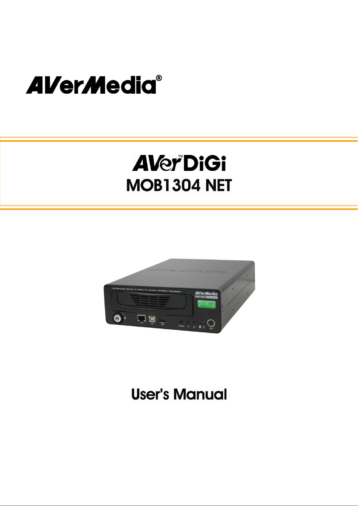
(1) AVerDiGi MOB1304 NET unit
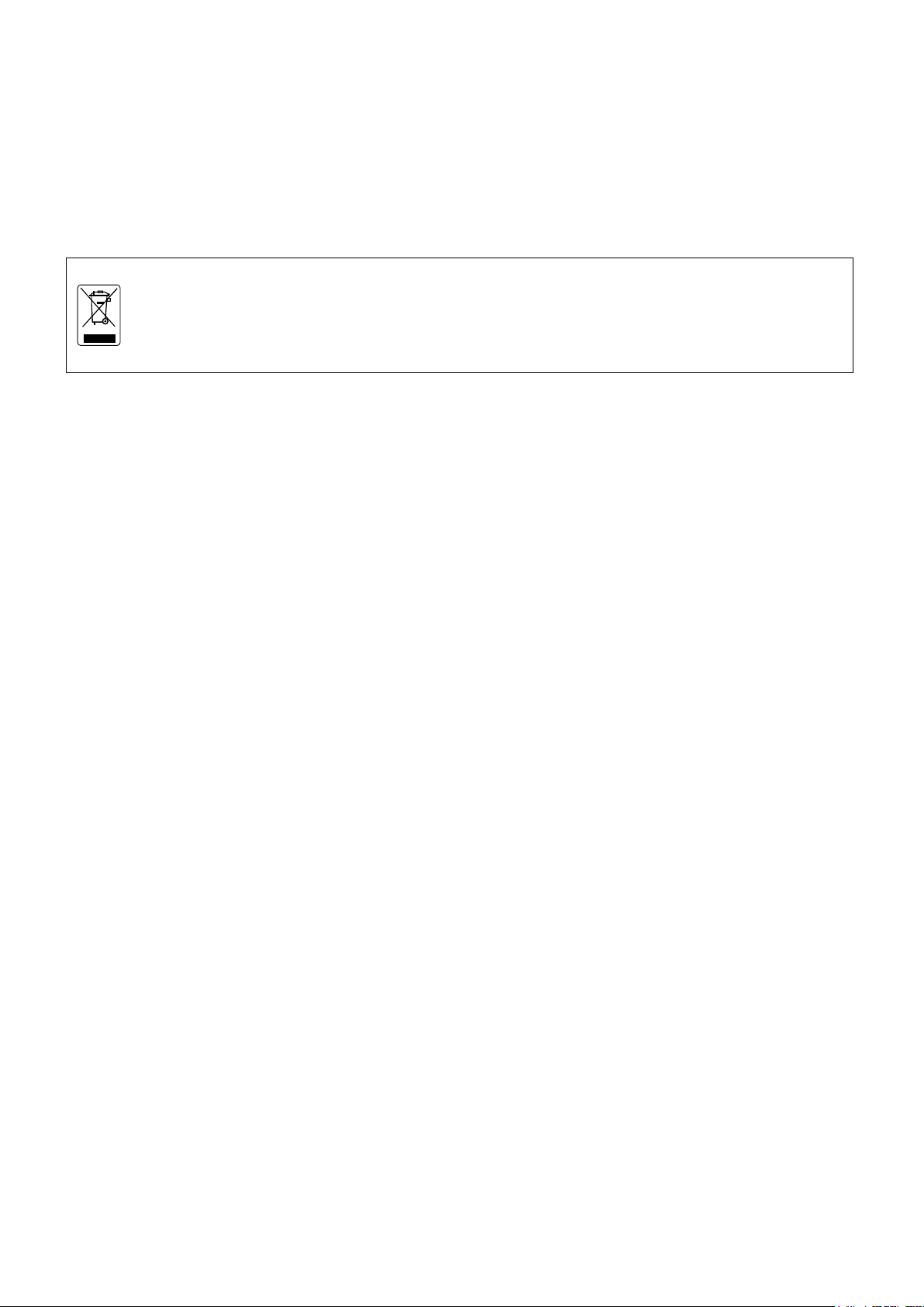
(2) Remote control (batteries are included)
** image of remote control just for reference only
(3) USB cable
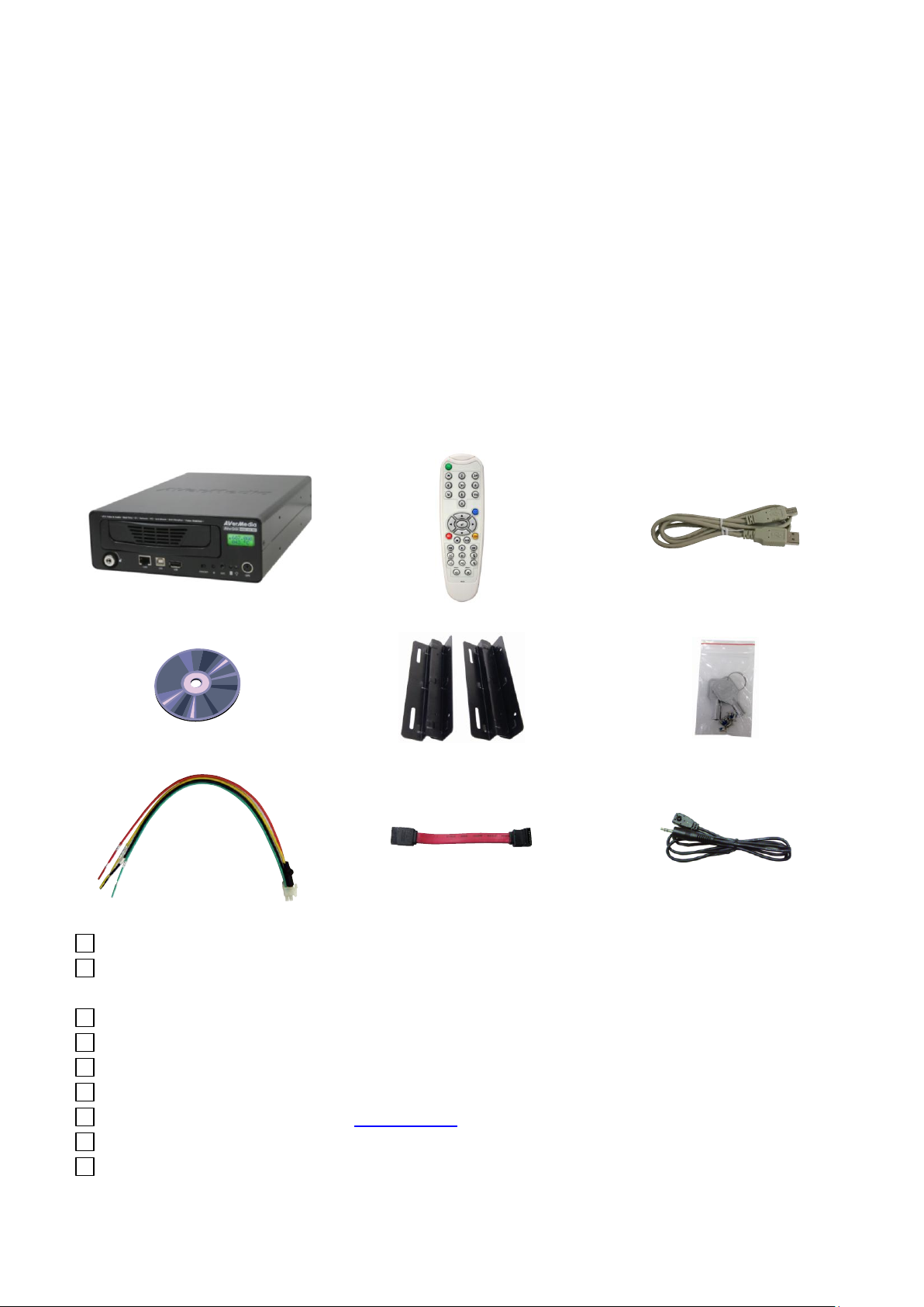
(4) Software CD (User Manual and Quick Guide are included)
(5) Z-brackets (Screws are included)
(6) Removable hard disk drawer accessories (with spare screws)
(7) Power cable (Please refer Chapter 1.4.3 for more detail)
(8) SATA cable
(9) An extended IR sensor cable
AVerDiGi MOB1304 NET is a 4-channel stand-alone DVR unit for mobile solution that can be
installed on the vehicle for security monitoring. It provides real-time monitoring and digital
recording of surveillance video. Up to 4 video cameras and 4 sensor devices can be hooked up
to this DVR unit. It also provides one audio input and output channel.
DVR unit can be controlled through LCM with remote control. Also, With the On-Screen-Display
(OSD) menu, user can customize video recording setting, sensor and alarm settings, password
protection, hard drive recycling, and more.
Surveillance video is recorded in high-quality MPEG4 format. Three recording modes are
supported; D1 Enhance mode can record video from each video camera in higher resolution at
30/25 fps and D1 mode can record video from each video camera in higher resolution at 60/50
fps and CIF Mode can record video in lower resolution and up to 120/100 fps (NTSC/PAL).
1.1 Package Content
1
Page 8
3G USB Dongle
(for 3G function)
GPS receiver
(for GPS function)
Name
Function
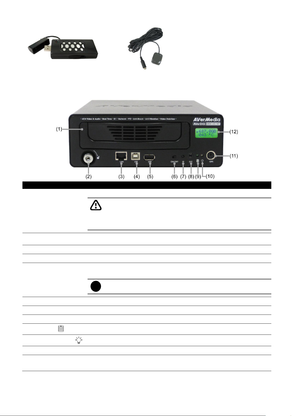
(1) SATA removable HDD
Drawer
For installing 2.5” or 3.5” SATA hard disk
The DVR unit supports hot swap of hard disk. User can unlock the hard
disk key lock and swap the hard disk while the DVR unit is running. The
DVR system will stop recording and shutdown hard disk when the hard
disk key lock is unlocked. Remove the hard disk when the hard disk stops
message display on the monitor/LCM panel.
(2) Key lock of hard disk
drawer
Lock/unlock the hard disk drawer
(3) Ethernet port
For Internet connection
(4) USB port
Connect to PC/NB for video backup or playback
(5) USB 2.0 Port
- To connect pen drive / external hard disk for backup
- To connect mouse for OSD menu controlling
i
The pen drive/ external hard disk must be in FAT32 format.
(6) Power switch
Power on / off the DVR unit
(7) IR sensor
Receive signal from the remote control to operate the unit
(8) IR sensor port
To connect an extended IR sensor cable
(9) HDD LED
Indicate running state of the hard disk. Lights when the HDD is running
(10) DVR power LED
Lights when the unit is on
(11) GPS connector
To connect the GPS device
(12) LCM display panel
- To configure DVR unit without connecting to monitor
- To display system status and setup message
1.1.1 Optional Accessories
1.2 Front Panel
2
Page 9
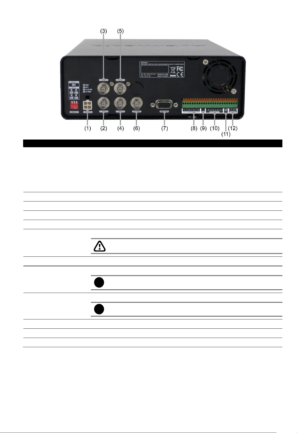
1.3 Back Panel
Name
Function
(1) Power cable
Connecting the power cord. The power cord divide into 4 lines and each line has
sticker on it for function description.
GND (Black): Power connecting negative(-)and camera negative(-)
12V~24V(Red): Power connecting positive(+)
ACC(Green): Connect with the ACC line of vehicle
12V Out(Yellow): Camera connecting positive(+)
(2) CH1
Input the video camera signal and display it on channel 1
(3) CH2
Input the video camera signal and display it on channel 2
(4) CH3
Input the video camera signal and display it on channel 3
(5) CH4
Input the video camera signal and display it on channel 4
(6) Video Out (BNC)
Output the video signal to a TV(Call Monitor)
The DVR unit supports dual video output – Video Out and VGA Out.
(7) VGA Out
Output the video signal to a LCD monitor
(8) Audio In
Input the audio signal from a microphone or audio input device.
i
Microphone with its own power supply is necessary and the internal
amplification must be used.
(9) Audio Out
Output the audio signal to a speaker
i
The audio out device with its own power supply is necessary.
(10) Sensor In
Support 4 sensor device
(11) Alarm Out
Support 1 relay device (Relay: 1A @ 125V AC/30V DC)
(12) RS485
For PTZ camera connection
3
Page 10
i
- For hard disk spec, please referring to http://www.avermedia.com/AVerDiGi/ → Products
→ Mobile DVR → AVerDiGi MOB1304 NET → Hardware Recommendations
- The DVR unit support hot swapping. Therefore, user can swap the hard disk without
shutdown the DVR unit.
The “compatible hard disks” indicated in the above recommendation list only means that these
commercially available hard disks were tested with AVerMedia products and functioned well
under normal operation conditions. AVerMedia does not guarantee or provide warranties,
explicitly, implied or statutory with respect to the reliability of the hard disk function or its
compatibility. In no event AVerMedia shall be liable for damages, with respect to any business
interruption of clients, lost profits, loss of programs or other data on your information handling
system or otherwise. This includes direct, indirect, incidental, special, or consequential
damages, resulting from the incompatibility caused by the usage of these hard disks, even if
AVerMedia has expressly advised about the risk of such damages. The entire risk arising out of
the use of any information attached here with is borne by the recipient.
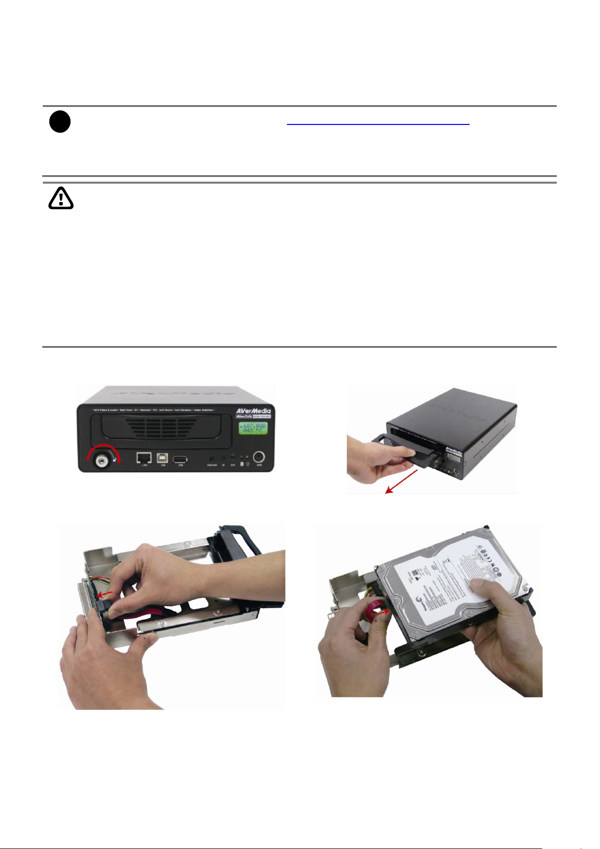
1. Using key to unlock the hard disk key lock
2. Pull removable hard disk drawer out
3. Connect the SATA cable to the connector that inside
of hard disk drawer.
4. Connect another side of SATA cable to the hard
disk.
1.4 Setting Up the DVR Unit
1.4.1 Installing the Hard Disk
The DVR unit allows you to install one SATA hard disk.
Follow the illustrated instructions below to install the hard disk:
4
Page 11
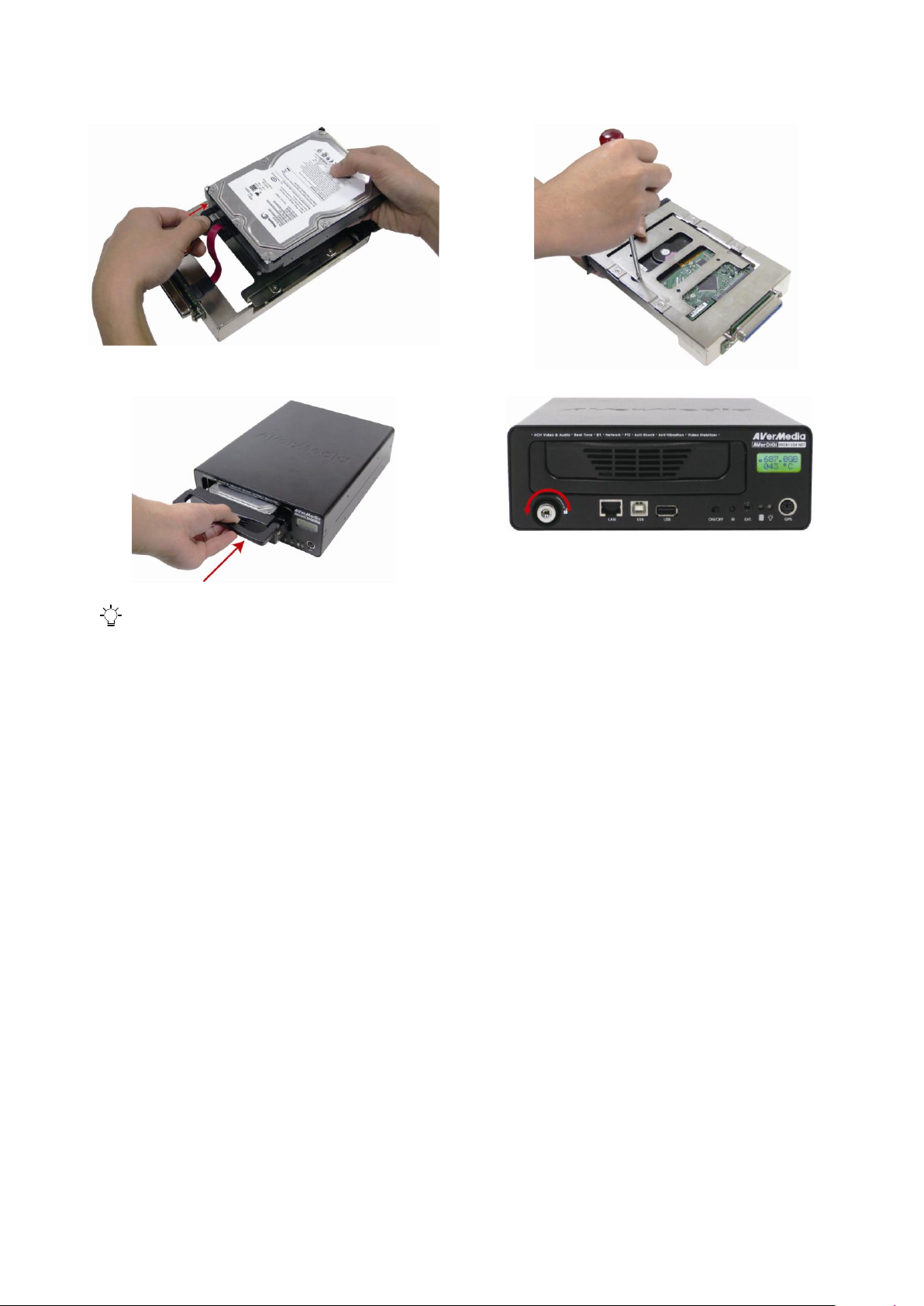
5. Connect the power connector to the hard disk. And
then, put the hard disk inside the hard disk drawer
carefully. Please watch out the SATA cable when
put the hard disk into the hard disk drawer.
6. Using the both hand to hold and turn the hard disk
drawer over carefully. And then, adjust the hard disk
to appropriate position and secure the hard disk with
4 screws on the hard disk drawer.
7. Slide the hard disk drawer back into DVR unit.
8. Using key to lock the hard disk key lock
9. You may now connect all the devices, cables, and power. When the power is connected, the Power LED light
turns on
5
Page 12
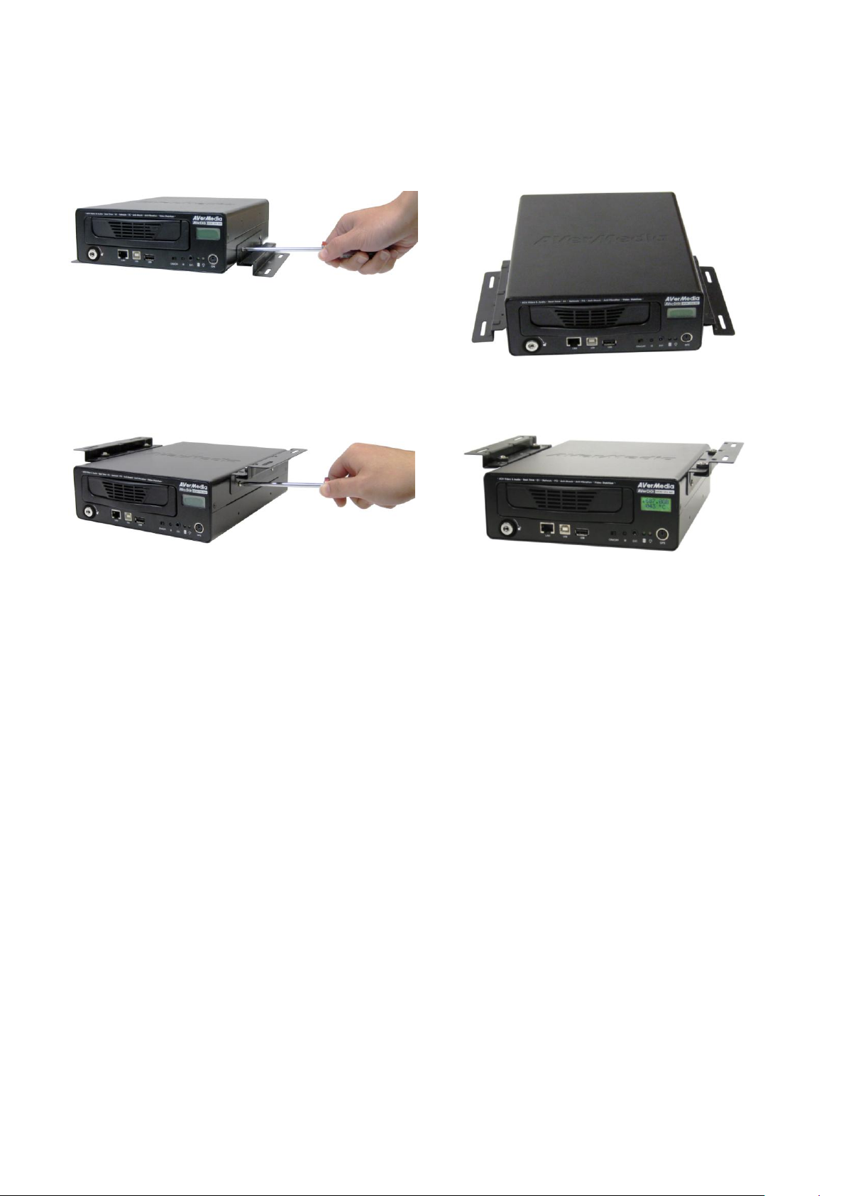
1. Screwed the Z-bracket for both side.
2. Finished look
1. Screwed the Z-bracket for both side.
2. Finished look
1.4.2 Mounting the DVR Unit
The DVR unit can be mounted in two ways. User can uses the Z-brackets (4 screws included) to
mount the DVR unit as the figure below shown.
1.4.2.1 Installing the lower Z-brackets
1.4.2.2 Installing the Upper Z-brackets
6
Page 13
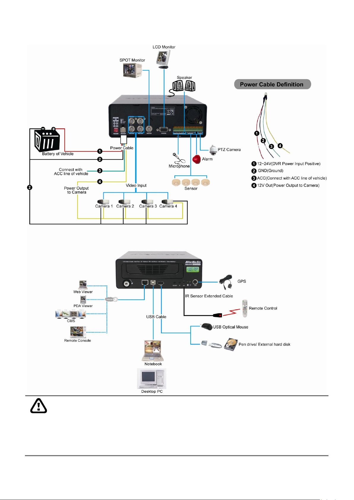
1.4.3 Connecting Devices
- To avoid installing the MOB DVR unit in moisture location.
- To make sure the install location provides sufficient ventilation to keep proper operating
temperature between 45°C and 5°C.
- Leave a front space that is enough for sliding removable hard disk drawer in and out.
- Secure the MOB DVR unit to avoid unauthorized person to damage or tamper the unit,
wires, cameras, and any accessories.
The following figure is a sample of DVR unit with all devices‟ connection:
7
Page 14
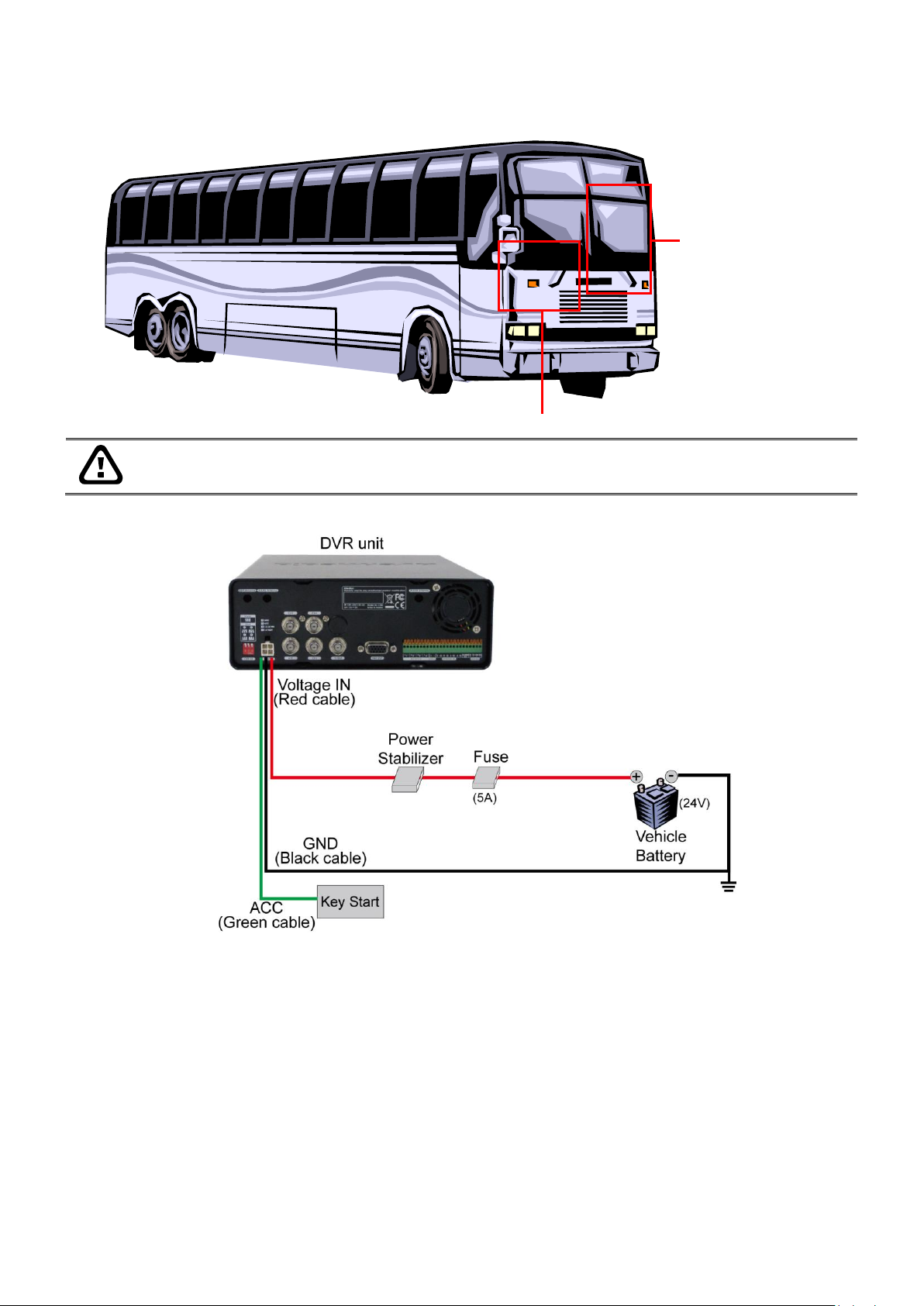
Under driver seat
top or under storage box
Do not install DVR unit near the door side and on the floor, those locations are high quake
spot and are easily to damage the DVR unit.
1.4.3.1 Install on the Bus
DVR Install Location:
Circuit diagram:
8
Page 15
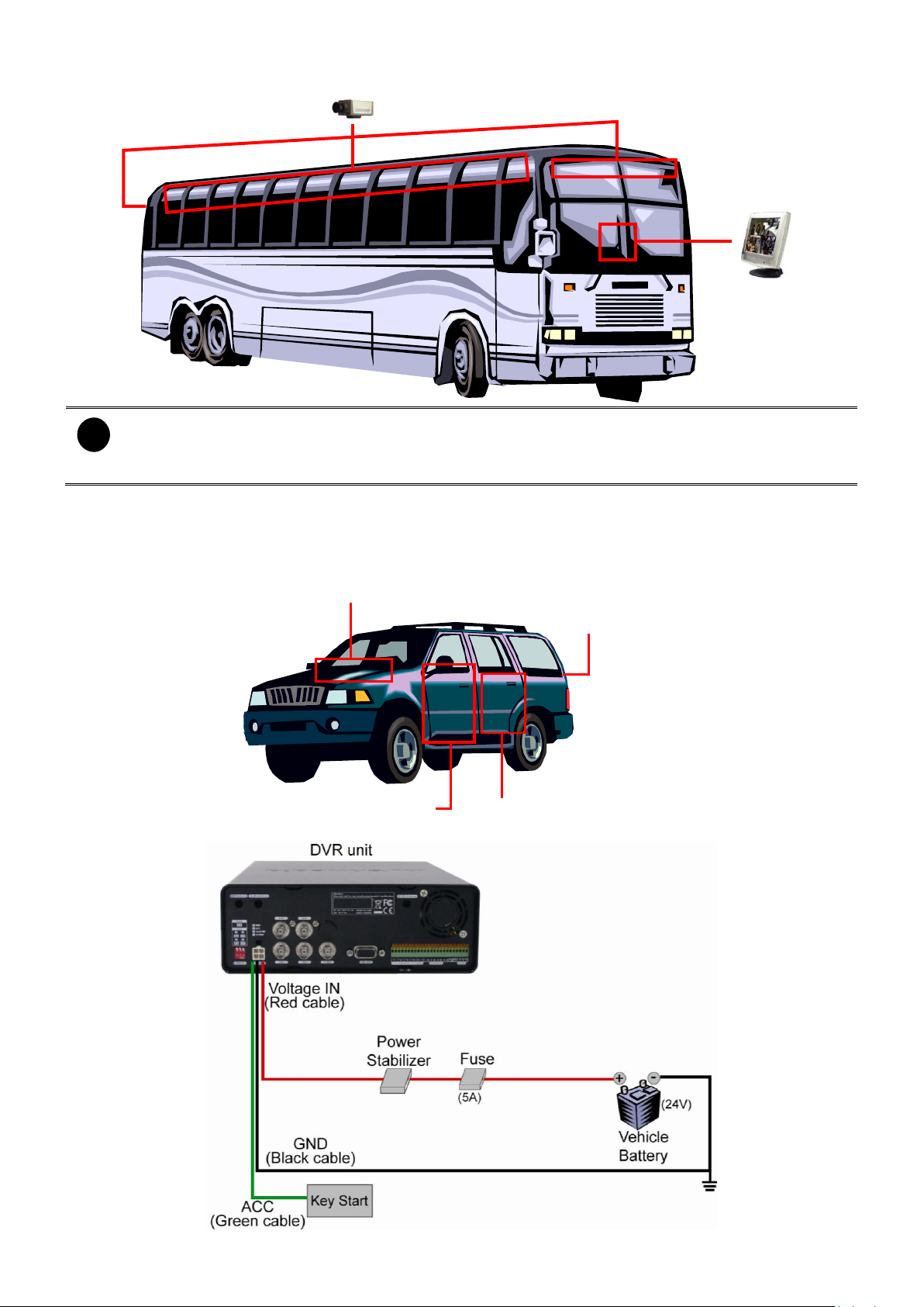
Camera/LCD Monitor Install Location:
LCD Monitor
Camera
i
- The LCD monitor power can connect to the ignition of bus.
- The camera power is connected to the DVR camera power cable and plugs the video cable
into DVR video input.
Under driver seat
top or under storage box
Hang inside the truck
Under passenger seat
1.4.3.2 Install on the Car
DVR Install Location:
Circuit diagram:
9
Page 16
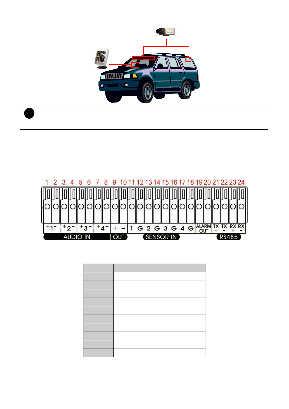
LCD Monitor
Camera
i
- The LCD monitor power can connect to the ignition of bus.
- The camera power is connected to the DVR camera power cable and plugs the video cable
into DVR video input.
Pin #
Definition
1
Audio 1 input signal +
2
Audio 1 input signal -
3
Audio 2 input signal +
4
Audio 2 input signal -
5
Audio 3 input signal +
6
Audio 3 input signal -
7
Audio 4 input signal +
8
Audio 4 input signal -
9
Audio output signal +
10
Audio output signal -
Camera/LCD Monitor Install Location:
1.4.4 Connecting the Sensor/Relay/RS485 Device
The Sensor and Alarm ports enable you to connect (4) sensor inputs and (1) relay outputs. Just
connect the external sensor and relay pin directly to the pinhole. The RS485 ports allows user to
connect the PTZ camera to the DVR unit. Check the table below and locate which pinhole is
assigned to sensor input, relay output, or RS485.
1.4.4.1 Audio, Sensor, Relay and RS485 pinhole allocation
Audio in and out pinhole:
10
Page 17
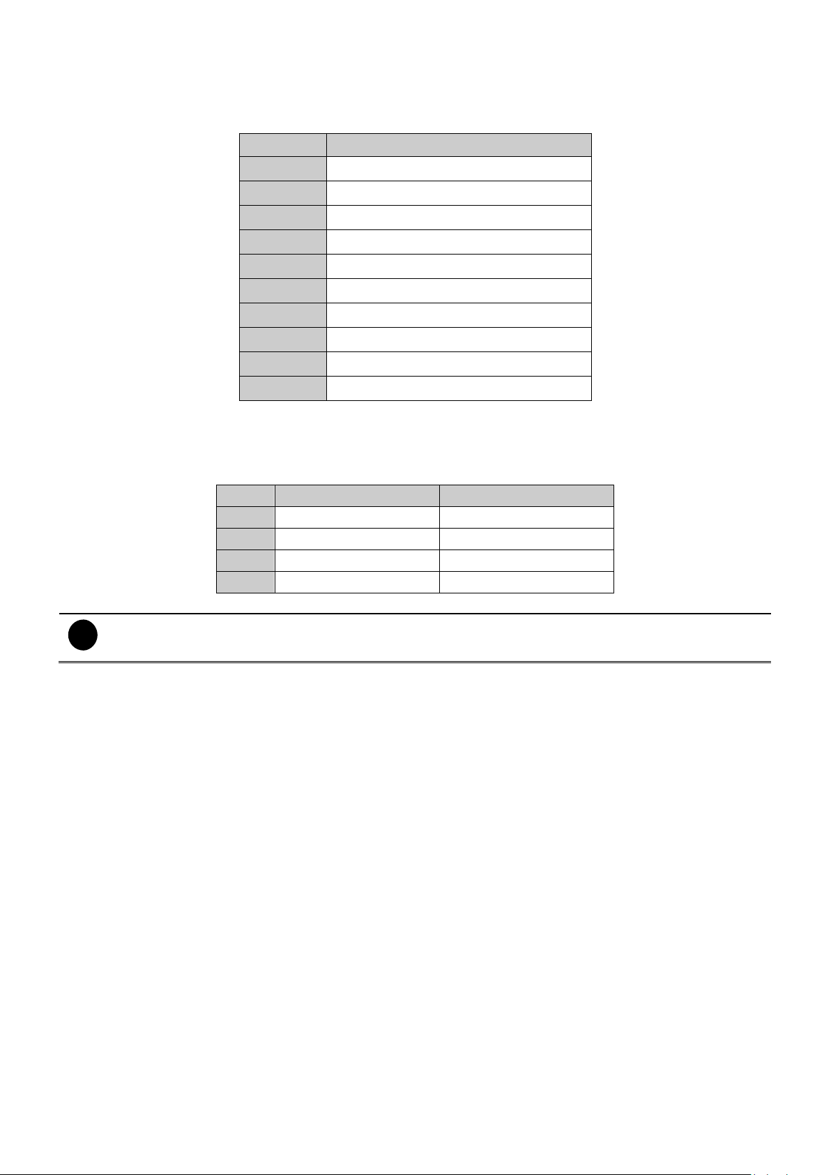
Sensor in and Alarm pinhole:
Pin #
Definition
11
Sensor 1 signal
12
Sensor 1 Ground signal
13
Sensor 2 signal
14
Sensor 2 Ground signal
15
Sensor 3 signal
16
Sensor 3 Ground signal
17
Sensor 4 signal
18
Sensor 4 Ground signal
19
Relay signal
20
Relay signal
DVR site
PTZ site
TX+
RS485 TX+ signal
RS485 RX+ signal
TX-
RS485 TX- signal
RS485 RX- signal
RX+
RS485 RX+ signal
RS485 TX+ signal
RX-
RS485 RX- signal
RS485 TX- signal
i
If user uses the 2 wires for the PTZ camera connection, please connect to the RS-485 TX+ and TX- of the
DVR site.
The signal from the sensor (i.e., infrared sensors, smoke detectors, proximity sensors, door
sensors, etc.) is being transmitted to the unit and this triggers the system to respond and send
signal to relay device (i.e., alarm, telephone etc).
RS-485 pinhole:
When connect PTZ camera through RS485 interface, please refer to the following pin definition to
connect the DVR and PTZ.
11
Page 18
Button
Function
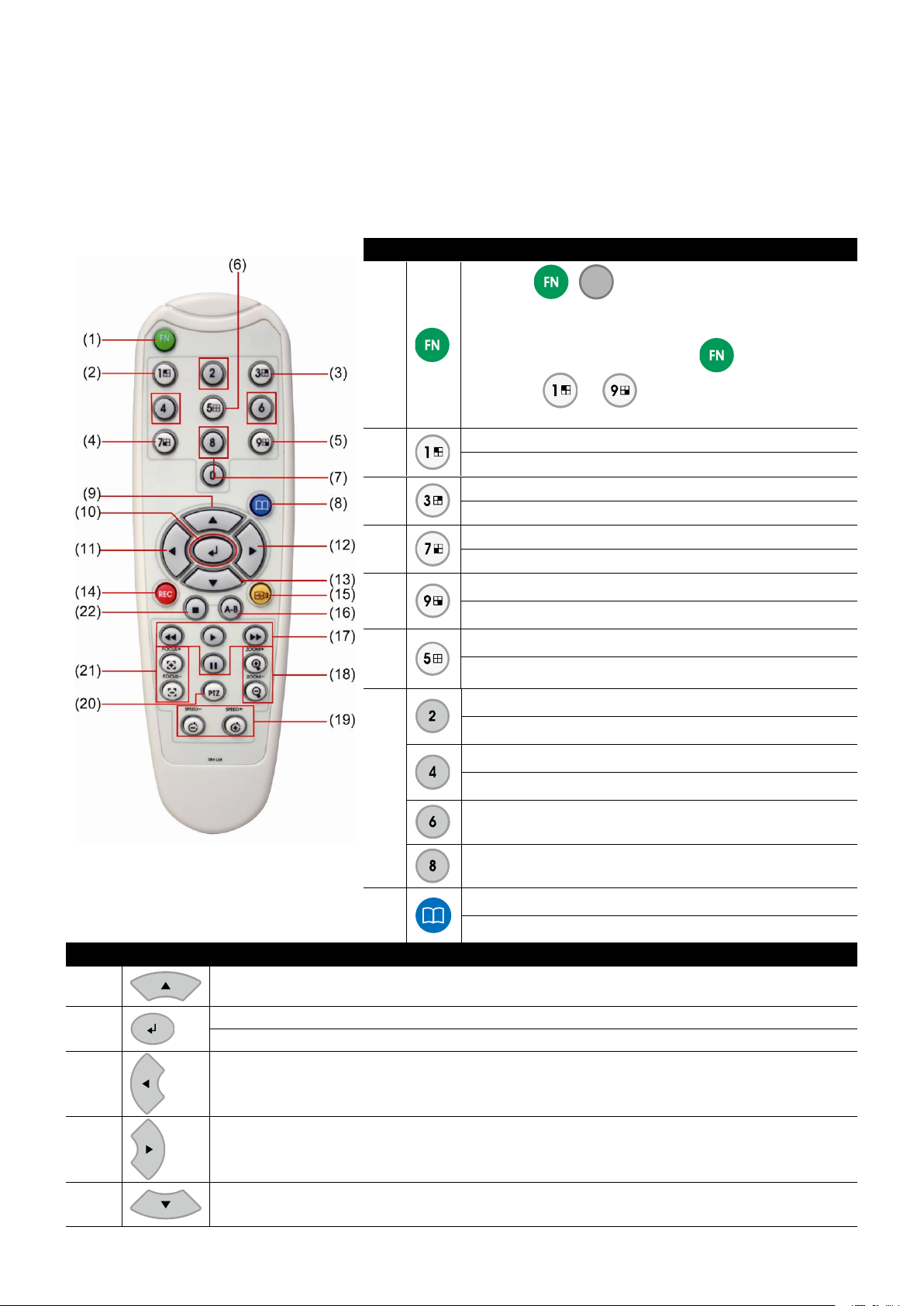
(1)
-
Press +
0
, the DVR system will instantly
playback the recorded file that is recorded 60
seconds before.
-
In multiple DVR mode, press + number
button( ~ ) can switch to the selected
DVR.
(2)
As a Channel 1 in preview and playback mode
As a channel 1 and preset position in PTZ mode
(3)
As a Channel 2 in preview and playback mode
As a channel 3 and preset position in PTZ mode
(4)
As a Channel 3 in preview and playback mode
As a preset position in PTZ mode
(5)
As a Channel 4 in preview and playback mode
As a preset position in PTZ mode
(6)
Switch to QUAD mode in preview and playback mode
As a preset position in PTZ mode
(7)
As a channel 2 in PTZ mode
As a preset position in PTZ mode
A s a channel 4 in PTZ mode
As a preset position in PTZ mode
As a preset position in PTZ mode
As a preset position in PTZ mode
(8)
To enter the OSD Main menu
Exit from the main menu or sub-menu display
Button
Function
(9) To move up the selection and select the items in the menu list or change the settings.
(10)
Make a selection To play the video
Enter sub-menu
(11)
To move the selection to the left
(12)
To move the selection to the right
(13)
To move down the selection and select the items in the menu list or change the settings.
1.5 Familiarizing the Remote Control Buttons
Use the Remote control to operate the OSD menu on surveillance screen.
Please refer to the remote control that user has got for following description of remote control
functions.
1.5.1 New Type Remote Control
12
Page 19

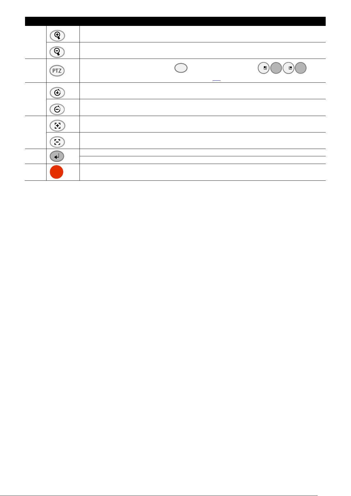
Button
Function
(14)
Start video recording
(15)
To backup the video segment to external flash memory ( See also 1.5.4).
(16)
Set a playing recorded video from A point to B point segment and repeat playing on
surveillance screen(See also 1.5.3)
(17)
Fast play the video playback at the speed of 2x, 4x, 8x ,16x, 32x, or 64x
When
button has pressed, and press can go to next frame
To start play recorded file / To enter playback menu
Rewide the video playback at the speed of 2x, 4x, 8x ,16x, 32x, or 64x
When
button has pressed, and press can go back to last frame
Pause the playing
(18)
To zoom in view of PTZ camera
To zoom out view of PTZ camera
(19)
PTZ camera control button. Press + camera channel button( )can
enter PTZ mode to control PTZ camera.(see also 1.6)
(20)
To speed up movement of PTZ camera lens
To speed down movement of PTZ camera lens
(21)
To focus in PTZ camera lens
To focus out PTZ camera lens
(22)
Stop playing / Stop recording
13
Page 20
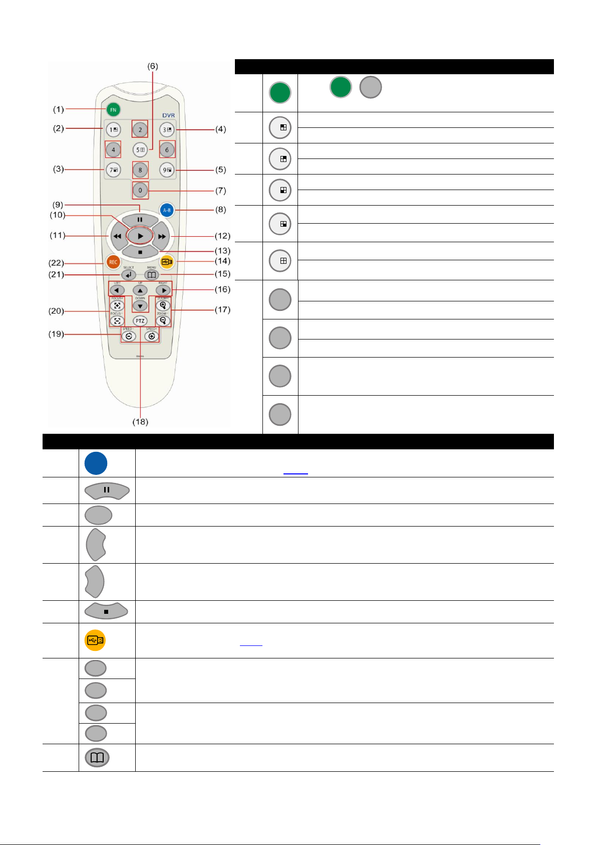
Button
Function
(1)
FN
Press
FN
+
0
, the DVR system will instantly
playback backward the 60 seconds of the recorded file.
(2)
1
As a Channel 1 in preview and playback mode
As a channel 1 and preset position in PTZ mode
(3)
3
As a channel 2 in preview and playback mode
As a channel 3 and preset position in PTZ mode
(4)
7
As a channel 3 in preview and playback mode
As a preset position in PTZ mode
(5)
9
As a channel 4 in preview and playback mode
As a preset position in PTZ mode
(6)
5
Switch to QUAD mode in preview and playback mode
As a preset position in PTZ mode
(7)
2
As a channel 2 in PTZ mode
As a preset position in PTZ mode
4
A s a channel 4 in PTZ mode
As a preset position in PTZ mode
6
As a preset position in PTZ mode
8
As a preset position in PTZ mode
Button
Function
(8)
A-B
Set a playing recorded video from A point to B point segment and repeat playing on
surveillance screen(See also 1.5.3)
(9) Pause the playing
(10)
¡¡
To play the video
(11)
¡¡
¡¡
Decrease the video playback at the speed of 2x, 4x, 8x, 16x, 32x, or 64x
(12)
¡¡
¡¡
Fast play the video playback at the speed of 2x, 4x, 8x , 16x, 32x, or 64x
(13)
Stop playing / Stop recording
(14)
USB backup(see also 1.5.4)
(15)
¡¡
To move the selection to the left and right
¡¡
¡¡
To go up and down and select the items in the menu list or change the settings
¡¡
(16)
To enter the OSD Main menu / Exit from the main menu or sub-menu display
1.5.2 Old Type Remote Control
14
Page 21
Button
Function
(17)
ZOOM+
To zoom in view of PTZ camera
ZOOM-
To zoom out view of PTZ camera
(18)
PTZ camera control button. Press
PTZ
+ camera channel button(
1
2
3
4
)can
enter PTZ mode to control PTZ camera.(see also 1.6)
(19)
SPEED+
To speed up movement of PTZ camera lens
SPEED-
To speed down movement of PTZ camera lens
(20)
FOCUS +
To focus in PTZ camera lens
FOCUS -
To focus out PTZ camera lens
(21)
Make a selection
Enter to configure mode of selection
(22)
REC
Start video recording
15
Page 22

¡¡
A-B
A-B
A-B
1.5.3 Using AB Segment Function
AB segment function allow user to set a video segment from A to B point and play on the
surveillance screen until user stop. User also can backup AB segment video file to pen drive or
external hard disk (see also 1.5.4).
1. Press
(play) to call out the
SEARCH MODE
menu to find the recorded video that user
wants to playback.(see also 2.3)
2. Select
-
-
-
TIME SEARCH, FILE LIST
TIME SEARCH
EVENT LIST
SMART MOTION SEARCH
: search by date and time
: search by condition
3. During the playback, press
again to set the B point of video segment. On the surveillance screen will display “
, or
SMART MOTION SEARCH
.
: search by motion event
to set the A point of video segment. And then, press
A-B
repeat playing the AB point video segment which user has set. To cancel AB segement, press
again.
” and
16
Page 23
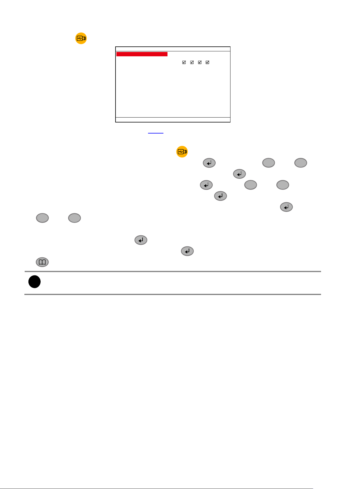
1.5.4 Using USB Backup Button
VIDEO BACKUP SETUP
START 2009 / 01 / 09 11:36:21
END 2009 / 01 / 09 11:36:21
BACKUP CH
BACKUP SIZE ~0MB
BACKUP
1 2 3 4
¡¡
¡¡
¡¡
¡¡
¡¡
¡¡
i
-
If the external hard disk is first time using, please format to FAT32 format.
-
The external hard disk needs to be powered by external power.
User can press button to backup the AB segment video file.
1. Set the AB segment video (see also 1.5.3).
2. Plug in pen drive or external hard disk to DVR system.
3. During the AB segment video playback, press button.
4. Select the
START
time of backup time by pressing the
button, using
and
setup the date and time. To confirm the value or selection, press .
5. Select the
to set the end of backup time. Press
END
and use
and
to setup
the date and time. To confirm the value or selection, press .
6. Select the
and
7. Select the
8. Select the
BACKUP CH
to select the channel.
BACKUP SIZE
BACKUP
to setup the channel that user wants to backup. Press and use
to calculate the total size of backup file.
and press to start backup.
9. When backup confirm message appear, press (YES) to start backup file or press
(NO) to exit backup mode.
to
17
Page 24
PTZ
1
2
3
4
PTZ
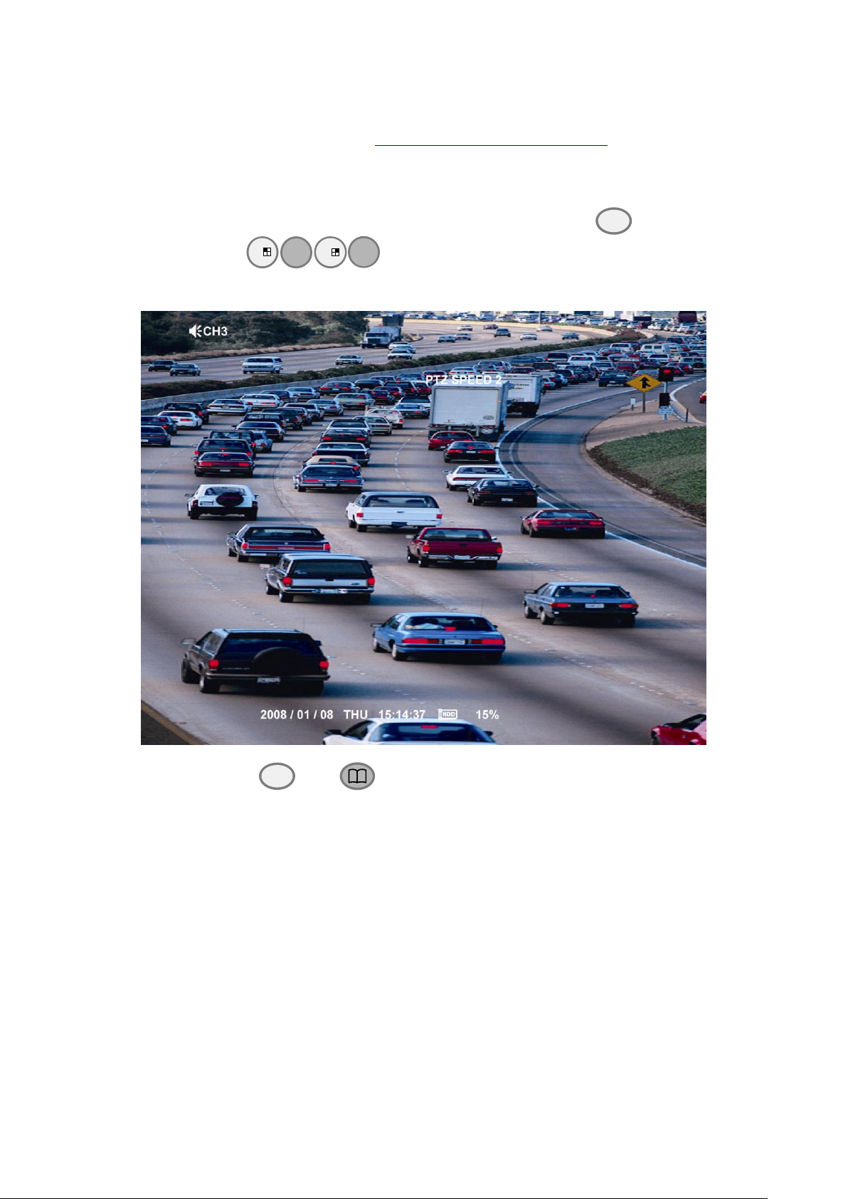
1.6 Controlling PTZ Camera
Using remote control, user can easily control PTZ camera at local site. Before starting, please go
to OSD menu to enable PTZ control (see 3.1 Menu Function: PTZ Setup).
1.6.1 To Enter the PTZ Mode
To control PTZ camera, user need to enter the PTZ mode first. Press
channel number button (
and display “
PTZ mode
” on the screen.
)
. The surveillance monitor will switch to single screen
button, and camera
To exit PTZ mode, press
and
button. Also, when user doesn‟t have any action over
1 minute, the system will automatically exit PTZ mode.
18
Page 25
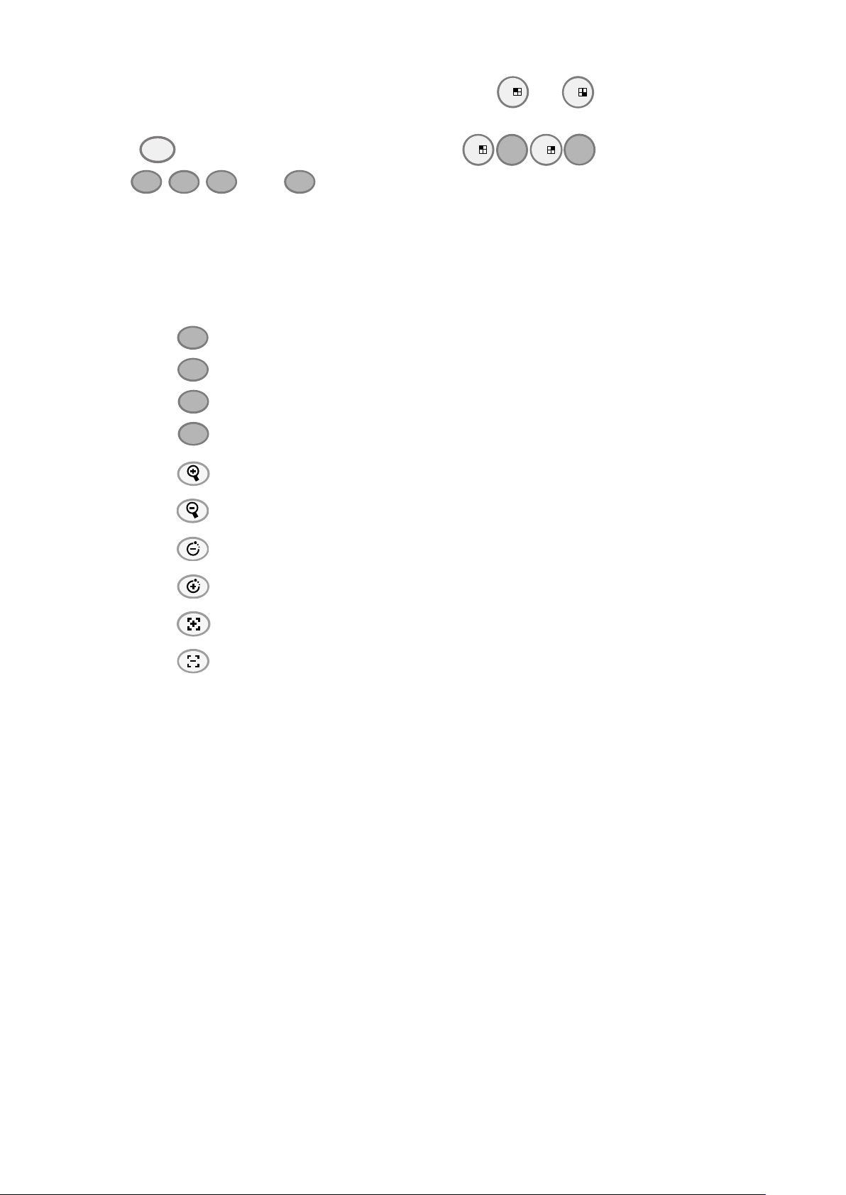
1.6.2 To Set Preset Position
1
9
PTZ
1
2
3
4
¡¡
¡¡
¡¡
¡¡
¡¡
To move the PTZ camera lens to the right
¡¡
To move the PTZ camera lens to the left
¡¡
To move the PTZ camera lens to go up
¡¡
To move the PTZ camera lens to go down
ZOOM+
To zoom in PTZ camera
ZOOM-
To zoom out PTZ camera
SPEED-
To speed down movement of PTZ camera lens
SPEED+
To speed up movement of PTZ camera lens
FOCUS +
To focus in PTZ camera lens
FOCUS -
To focus out PTZ camera lens
User can set 9 preset positions for PTZ camera. Using
to
button to set the preset
position.
1. Press
2. Using
and camera channel number button (
,
,
and
to adjust the PTZ camera to the position that user wants.
)
to enter PTZ mode.
3. Press any number button over 3 seconds and the position will be saved.
4. To move the PTZ camera to preset position, just press the number button.
1.6.3 To Control PTZ Camera
To move, adjust focus, and zoom in/out camera lens can be done by using some function
buttons on the remote control.
19
Page 26
The hard disk drawer must be locked in order for DVR system to detect the hard disk when
DVR system starts up.
The default login ID is ADMIN(case sensitive) and default password is 111111.
SYSTEM INITIALIZE
FW VERSION B6. 01. 01. 00. 03
SELF CHECK SUCCESS
HDD STATUS WAIT . . . .
STORAGE SETUP
HDD OVERWRITE
HDD SIZE 953, 849MB
HDD USED 0MB 0%
HDD FORMAT
VIDEO BACKUP
¡¡
¡¡
¡¡
¡¡
Chapter 2 Operating the MOB1304 NET
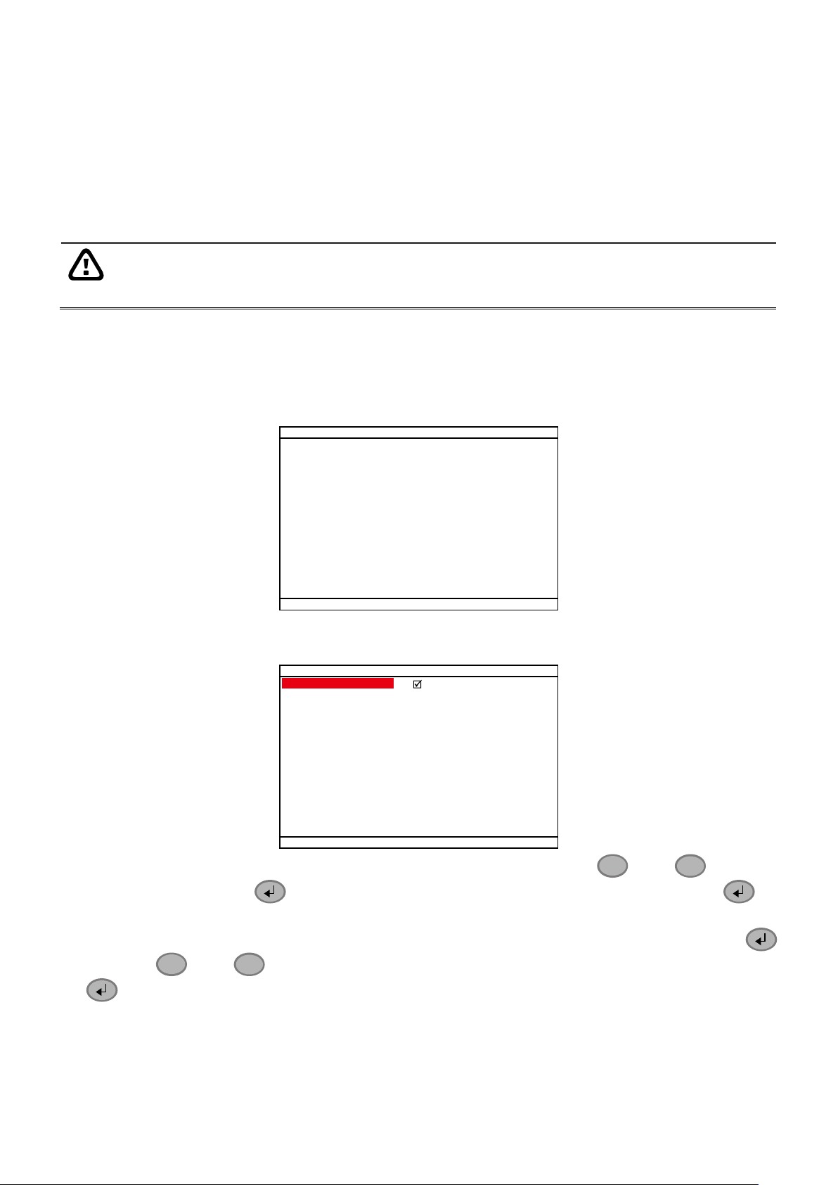
2.1 Using the MOB1304 NET for the First Time
For the first time using the DVR unit, suggest user connect with the LCD monitor and setup DVR
unit by using remote control. Once the DVR unit has been set up, user can operate the DVR unit
through the remote control and LED panel that is located front panel of DVR unit.
Following the below steps for first time setup.
1. Make sure all devices and power cables are well connected.
2. Turn on the DVR unit by switching the On/Off switch to ON.
3. User should see the
SYSTEM INITIALIZE
can see the current firmware version of the DVR system. The system will do the self checking
and hard disk detection.
window appear on the surveillance screen. User
4. When the hard disk has been detected, the
STORAGE SETUP
windows will appear on the
surveillance screen.
5. For the first time use hard disk, please format the hard disk. Using
and down and press to make a selection. Select
HDD FORMAT
enter HDD format screen.
6. To format the hard disk, the password (default password is
111111
and
to go up
and press to
) is required. Press
and use
and
to enter the password. When is done, select
EXECUTE
to start formatting.
20
and press
Page 27
CHECK PASSWORD
ENTER PASSWORD
EXECUTE
******
¡¡
¡¡
¡¡
¡¡
¡¡
¡¡
7. When hard disk format is done, please adjust the system date and time in order to have the
correct recording date and time.
8. Press to call up the OSD menu, and then, use
and
to select
SYSTEM
→
DATE/TIME
9. Press and use
10. And then, adjust the
and press to make a selection.
DATE
and
and
to select the
by using to make a selection and using
TIME
DATE FORMAT
.
and
to adjust the date and time.
11. When is done, the DVR system is ready to record.
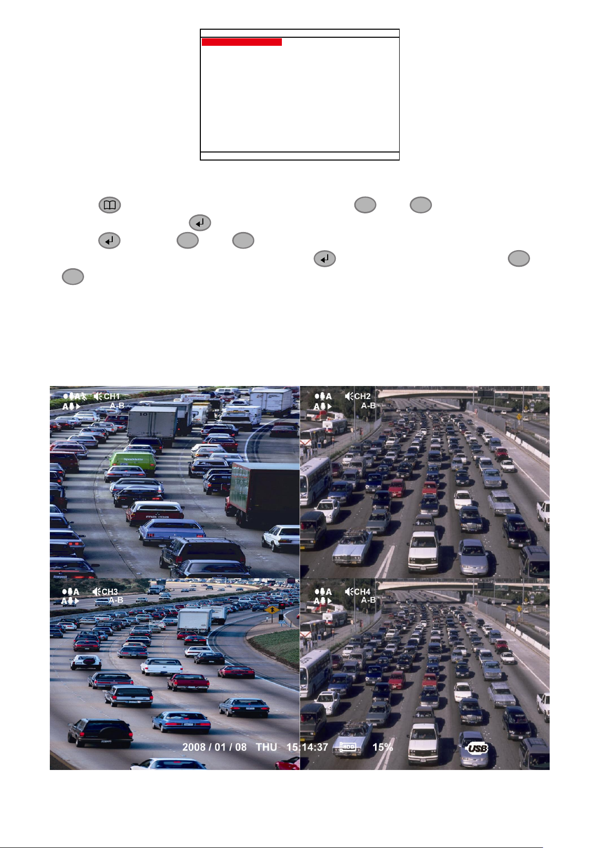
2.2 Surveillance Screen
This chapter will describe the symbols on the surveillance screen and screen display mode.
While DVR is playback, the record action will still working and the surveillance screen will display
the playback video.
Surveillance Screen
21
Page 28
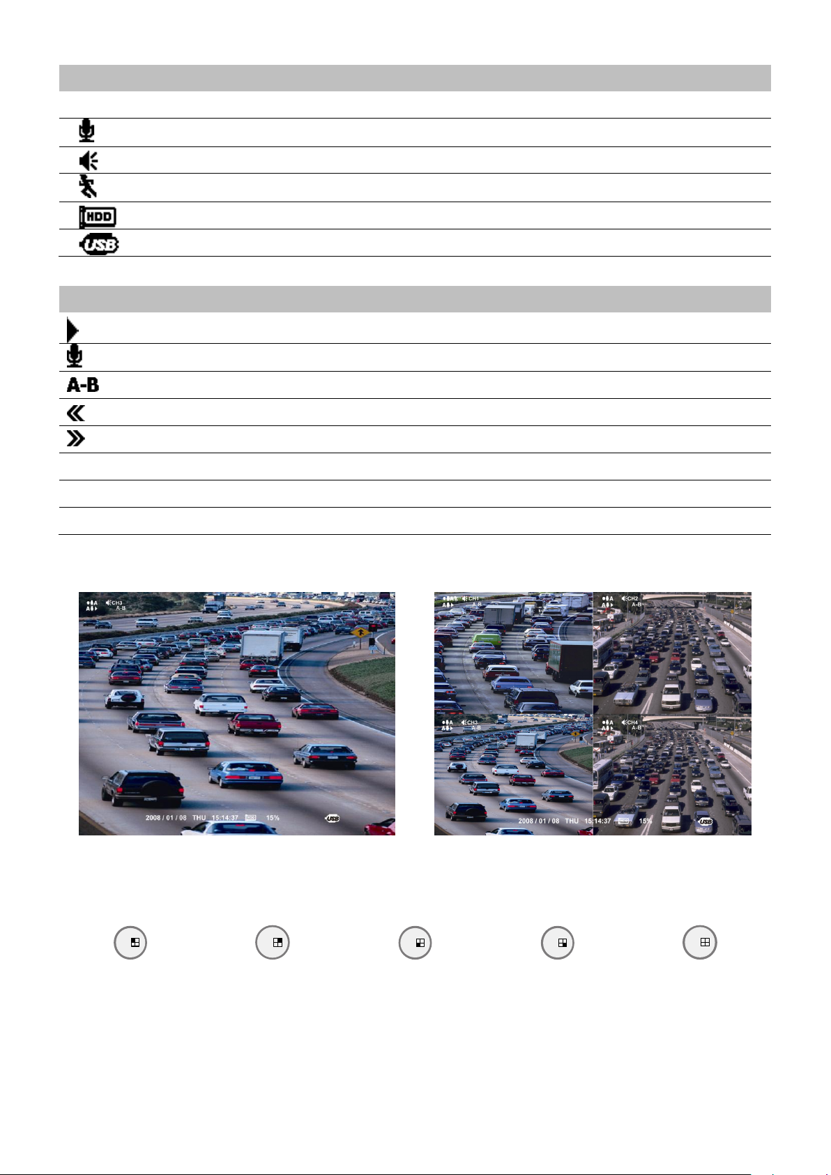
Symbol
Description
DVR is recording
Audio is enabled
Speaker is available
Motion recording
5%
Hard disk capacity
USB device is plugged
Symbol
Description
Playback the recorded video
Audio is enabled
AB segment is set and playing
Recorded video is playback at backward speed(2x, 4x, 8x, 16x, 32x, or 64x)
Recorded video is playback at faster forward speed(2x, 4x, 8x, 16x, 32x, or 64x)
A
Always Recording
B
Button Recording
L
Alarm Recording
Full Screen Mode
QUAD Screen Mode
1
CH1: Camera 1
3
CH2: Camera 2
7
CH3: Camera 3
9
CH4: Camera 4
5
QUAD:4-Channel
Preview Mode
Playback Mode
User can switch to display each channel in full screen or 4 channels in D1, D1 Enhanced, or CIF
record mode.
When you are in full screen preview, press the following buttons on the remote control and
control panel to switch to different channel, or preview all 4 channels:
22
Page 29
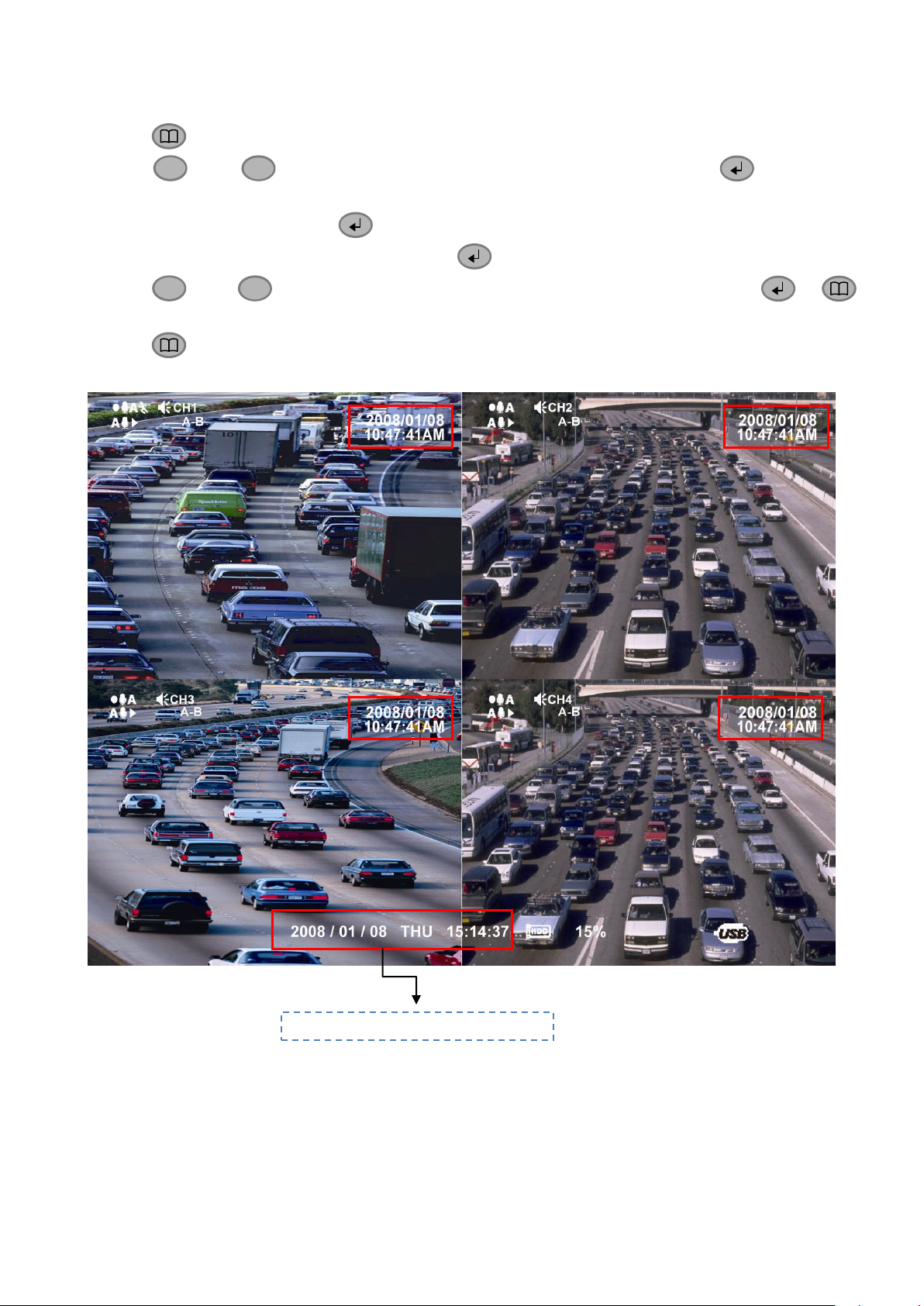
By enabling
¡¡
¡¡
¡¡
¡¡
DVR System current date and time
TIME STAMP
function, current date and time could be displayed on each channel
screen to verify the recording date and time. Please follow the below steps to enable
STAMP
.
1. Press to call out OSD menu.
TIME
2. Using
and
move the highlight to
CAMERA/REC
and press to make a
selection.
3. Select
GENERAL
4. And then, select
5. Using
and
and press to make a selection.
TIME STAMP
by pressing button.
to select the disable/enable of TIME STAMP and press or
to confirm.
6. Press to exit from OSD menu.
7. The current date and time will display on upper right corner of each channel screen.
23
Page 30
1. Press
¡¡
(play).
2. Use the
¡¡
and
¡¡
buttons to go up and down and select
TIME SEARCH, FILE LIST
, or
SMART MOTION SEARCH
. And
then, press to make a selection.
SEARCH METHOD
TIME SEARCH
FILE LIST
SMART MOTION SEARCH
TIME SEARCH (search by date and time):
1. In TIME SEARCH window, the
START TIME
and
END TIME
show the date and time from when the recording begins and
ends.
2. Press and use the
¡¡
and
¡¡
buttons to set the
SEARCH TIME
.
3. After SEARCH TIME has set, select
SEARCH EXECUTIION
and press to start searching.
TIME SEARCH
START TIME: 2009 / 01 / 09 11:36:21
END TIME: 2009 / 01 / 09 11:36:21
SEARCH TIME : 2009 / 01 / 09 11:36:21
SEARCH EXECUTION
4. When the playback file is found, the DVR system will start playback automatically.
FILE LIST (search by condition):
1. In FILE LIST window, press and use the
¡¡
and
¡¡
buttons to set the date and time for searching. And then,
select the
EXECUTION
to start searching.
2. The searching result will be list out. Using the
¡¡
and
¡¡
buttons to go up and down and press to make a
selection.
FILE LIST
MULTITIME SEARCH : 2009/01/09 11:36:21 EXECUTION
3. After make a selection, the
EVENT LIST
of each channel will
list out. Use the
¡¡
and
¡¡
buttons to the selection and
press to make a selection.
4. The selected event will start to playback.
EVENT LIST
CH1 NORMAL 14:23:25 - 14:23:33
CH2 NORMAL 14:23:25 - 14:23:33
CH3 NORMAL 14:23:25 - 14:23:33
CH4 NORMAL 14:23:25 - 14:23:33
1/1
2009/01/07
SMART MOTION SEARCH (search by motion event):
1. In SMART MOTION SEARCH window, the
START TIME
and
END TIME
show the date and time from when the recording
begins and ends.
2. Use the
¡¡
and
¡¡
press to set
SEARCH START
TIME
and
SEARCH END TIME
for searching period.
3. Then, Select the
CHANNEL
that wants to set search area.
SMART MOTION SEARCH
START TIME: 2009 / 01 / 09 11:36:21
END TIME: 2009 / 01 / 09 11:36:21
SEARCH START TIME : 2009 / 01 / 09 11:36:21
SEARCH END TIME : 2009 / 01 / 09 11:36:21
CHANNEL : 01
SEARCH AREA
SEARCH EXECUTION
2.3 Playback the Video
To playback recorded video, user doesn‟t need to stop recording. DVR system supports
recording and playback simultaneously.
2.3.1 To Playback Video
24
Page 31

4. And then, select
SEARCH AREA
to mark an area to search.
Use the
¡¡
,
¡¡
,
¡¡
, and
¡¡
to move the block and
press to confirm. To exit, press .
5. To start searching, select the
SEARCH EXECUTION
.
6. When the playback file is found, the DVR system will start
playback automatically.
SEARCH AREA SETUP SCREEN
Listed below are the symbols of recording condition that will display on surveillance screen while playback mode
and record mode:
A – Always Recording
It records non-stop and automatically continue recording when interrupted.
L – Alarm Recording
It records when the alarm has activated.
B – Button Recording
It records when the
REC
record button is pressed.
N
– NO Recording
It doesn‟t record at all
The “
” play symbol would appear beside the channel number when you are in playback mode.
25
Page 32

2.4 Using the GPS Function
MOB DVR supports GPS that GPS data can be recorded and views the actual location by using
Google Earth.
2.4.1 Installing the GPS Device
User needs to install the GPS device on MOB DVR in order to receive the GPS data. GPS device
is an optional accessory, please contact with your local dealer for purchasing.
Following the below steps to install the GPS device on MOB DVR.
1. Plug the GPS connect cable into the GPS connector that is located on front panel of the MOB
DVR.
2. Placing the GPS device on the MOB DVR or on the place that user wants. The bottom of
GPS device has magnetism can stable attach on MOB DVR.
26
Page 33

2.4.2 Enabling the GPS Function
MAIN MENU
CAMERA/REC
SCHEDULE
EVENT SETUP
DISPLAY
STORAGE
NETWORK
SYSTEM
MISCELLANEOUS
MISCELLANEOUS SETUP
MUTLIPLE DVR
GPS
GSM
3G
ENTERTAINMENT
¡¡
¡¡
LATITUDE
LONGITUDE
DISPLAY MESSAGE
HEADING
SPEED OVER GROUND
KM / MILE KM
GPS SETUP
LATITUDE
LONGITUDE
DISPLAY MESSAGE
HEADING
SPEED OVER GROUND
KM / MILE KM
GPS SETUP
GPS must be enabled in order to receive the GPS data. Following the below steps to enable the
GPS function on the MOB DVR.
1. Press or use mouse right-click on the screen to call out the OSD menu.
2. Select the
Miscellaneous
3. Select GPS from Miscellaneous menu.
from Main menu.
4. Enable the data that user wants to receive and select unit of the distance (KM or Mile). To
enable the selection, press and use
To confirm the selection, press . User also can use mouse click the selection and use the
roller button to make a selection.
5. Press or use mouse left-click on the screen to exit from OSD menu. The GPS
configuration is completed.
and
to mark and un-mark the selection.
27
Page 34

2.4.3 Viewing the GPS Information
There are several ways to view the GPS data – in preview mode, WebViewer, UPC, Google
Earth, Remote Console, and CMS.
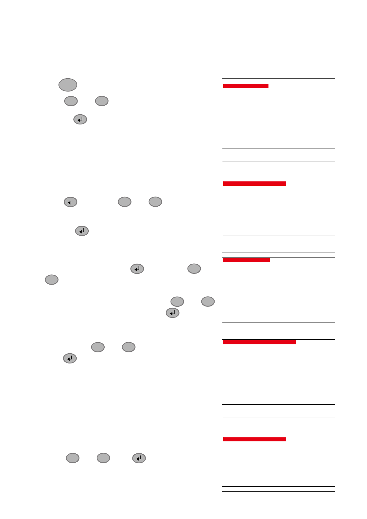
Preview Mode
After GPS has enabled, user should see the GPS data display on the preview screen. GPS data
will change when receive the new data.
WebViewer
User also can view the GPS information on the WebViewer through the internet. Open the
browser on your PC and enter the IP address of the MOB DVR. The detail of WebViewer, please
refer to Chapter 8. The coming GPS information will keep scrolling on the WebViewer UI.
28
Page 35

USB Playback Console
The recorded file that contains GPS data can be view when playback on USB Playback Console
(UPC).
1. Connect the HDD that contains recorded file from MOB DVR to your PC
2. Install the
3.
Run the UPC and select
4. Select the hard disk drive from
application from the Software CD on your PC.
UPC
DVR Recorded File(HD)
Select Disk
window and click OK.
from Disk Select and click OK.
5. The Event List windows will appear and list all recorded file. Select the file and preview the
selected file video. And then, click
recorded file list, click
. To go back to previous page, click
Next
to start playback on UPC. To go to next page of
OK
. To go to the specific
Pre
page, enter the page number and click GO.
6. The selected file will playback on the UPC and GPS will be seen while playback.
29
Page 36

i
The recorder file must contain GPS data in order to save in *.KML format and view on Google Earth.
Google Earth
1. By using Google Earth, user can view the video segment that has contains GPS data save
in *.KML format from UPC.
2. Install the Google Earth at http://earth.google.com.
3. Playback the recorded file from hard disk that is containing of recorded video data of MOB
DVR(see also Chapter 4.3.2)
4. During the playback, select a video segment that user wants to save in *.KML file format
(see also Chapter 4.3.1)
5. Click Export and select Export KML to save the video segment in *.KML format.
6. After installed Google Earth, double click the KML file that user has saved before.
7. The Google Earth will automatically activate and load the KML file.
8. User can view the actual location of recorded file according to the GPS data that MOB DVR
has recorded.
30
Page 37
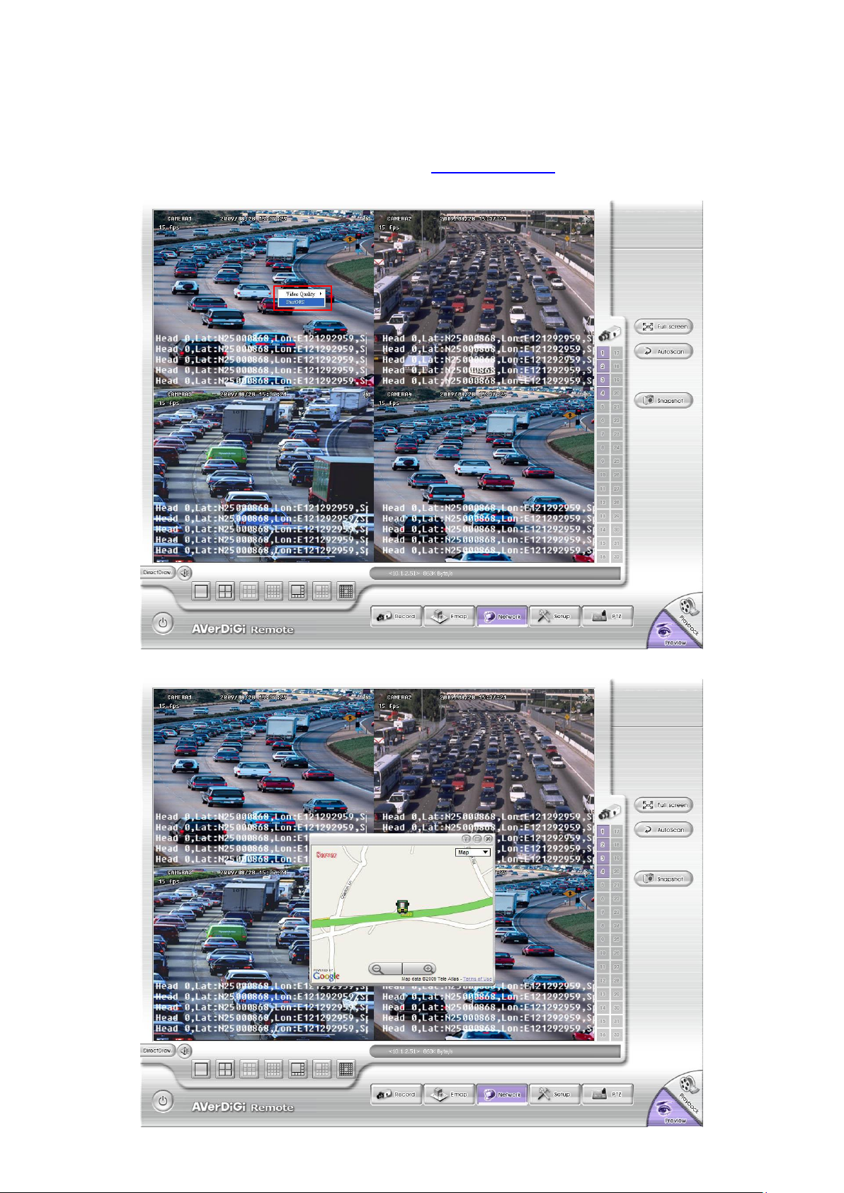
Remote Console
In Remote Console UI, user can enable GPS function to view the MOB DVR server location on
the Google map according to the GPS data that is received from GPS device has installed on the
MOB DVR system.
Follow the below steps to view the GPS data from the remote site.
1. Starting the Remote Console application (see Chapter 8.1 #(8)).
2. After connect to the MOB DVR server, right-click on the screen and select StartGPS.
3. The Google map window will show up on the Remote Console UI.
31
Page 38

Click to select different
display mode – Map,
Hybrid, Satellite, or
terrain.
Zoom in/out the Map
Exit the
Google Map
window
4. User can change display mode of the Google map and zoom in /out of the map.
CMS(Center Management System)
If user has monitored the MOB DVR server, user can view the GPS data on Monitor. Also, user
can view the location of MOB DVR server according the GPS data on the Google map.
Display the GPS Data on the Monitor:
Follow the below steps to display the GPS data on the Monitor center.
1. Run the CMS application on your PC. For more detail of CMS application, please refer to
CMS user‟s manual.
2. Click Setup in CMS Center interface.
3. Enter the password for authentication. When CMS configuration selection appears, click
DVR.
4. In DVR Setup window, select the MOB DVR server or add the MOB DVR server (please refer
to the CMS user‟s manual).
5. After selected the MOB DVR server, click Edit. The DVR Setting window will appear.
32
Page 39

i
Position of the GPS data display relate to the setting of
Monitor Text Setting
in the System setting of the
CMS.
6. Select the Video Quality to High, and then, mark the Show POS message to display the GPS data
on the Monitor.
7. Click OK to save and complete the change.
8. If the MOB DVR server hasn‟t been added any channels for monitoring, please refer to Chapter 4.3 of
the CMS user‟s manual to add the channels for monitoring.
9. Click Monitor to switch to the Monitor mode. User should see the GPS data display on Monitor UI as
following shown:
33
Page 40

Viewing the GPS Data on the Google Map:
Following the below steps to view the GPS data on the Google Map.
1. In the Monitor mode, right-click on the channel that is monitored from MOB DVR server.
2. The shortcut menu will appear. And then, select the Start GPS.
3. The Google Map window will show up.
4. Click on Maximum button to enlarge the Google Map window.
34
Page 41

5. Click Setup to setup the setting of the Google Map window.
Click to select the
display mode – Map,
Hybrid, Satellite, or
terrain.
Click to view different
split screen mode when
there is more than one
channel on the Google
map.
Listing all channels
that have been
enabled the GPS
function.
Zoom in/out the
Google Map.
To setup the setting
of the Google Map
View Windows.
Click it to switch to
full screen view.
Monitored DVR
server and channel
- Dialog mode: the way of the display of the Google Map
windows. User can select the server from Select Server list
in Simple mode.
- Map Mode: Mark All DVR in one map will enable all
channels display on one Google Map window.
6. To exit the Google Map, click X.
Simple Mode Full Mode
35
Page 42

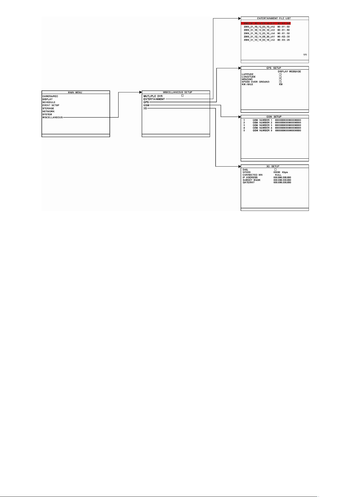
Chapter 3 OSD Navigation Tree
The follow figure is an OSD menu tree map. To call out the OSD menu, press button on
the remote control.
36
Page 43

37
Page 44

38 39
Page 45
Page 46

¡¡
¡¡
¡¡
¡¡
If the unit is currently recording the video, user may have to stop video recording to change the
settings.
OSD MENU
Description
MAIN MENU
CAMERA/REC
SCHEDULE
EVENT SETUP
DISPLAY
STORAGE
NETWORK
SYSTEM
MISCELLANEOUS
CAMERA/REC
Configure camera parameters, name and PTZ camera.
CAMERA / REC SETUP
GENERAL
CHANNEL SETTING
PTZ
CHANNEL NAME
GENERAL SETUP
GENERAL SETUP
RECORD MODE
TIME STAMP
DVR NAME
WATERMARK
PRE RECORD
AUTO RECORD
CIF
COMPANY
00 SEC
RECORD MODE
Select D1/CIF/D1 Enhance recording mode.
Under D1 mode, the video recording is in full screen resolution and
takes turns from one channel to the next one when Auto Scan
enables. Each channel is recorded only at a maximum frame rate of
15fps. User can switch to view the video in single full screen or QUAD
screen. Whereas in CIF mode, video recording is at a lower
resolution, but each video is recorded in 30fps/25fps (NTSC/PAL).
User can switch to view the video in single full screen or QUAD
screen
DVR NAME
Assign a name for the DVR unit. Maximum is 10 characters may
contain A~Z, 0~9, !, “, #, $, %, &, „, (, ), *, +, -, /, :, ;, <. >, ?, @, and
space.
TIME STAMP
Enable/disable the time and date display on the each channel.
AUTO RECORD
Enable/disable auto continue recording when interrupted (i.e., power
breakdown, video playback or configuration setup). It starts to record
after 5 second of idleness. This is applicable in Always Record mode.
3.1 Menu Function
To navigate in the OSD menu, press to call up and exit from the main menu or sub-menu
display. Then use
and
buttons to go up and down and select the items in the menu
list or change the settings. Use button to enter sub-menu or make a selection. User also
can use
and
buttons to move the selection to the left and right.
40
Page 47

OSD MENU
Description
GENERAL SETUP
RECORD MODE
TIME STAMP
DVR NAME
WATERMARK
PRE RECORD
AUTO RECORD
CIF
COMPANY
00 SEC
PRE RECORD
Set the pre-recording time in seconds when alarm has occurred.
CHANNEL SETTING SETUP
120 / 120 FPS
RECORD
ENABLE
AUDIO RECORD
PREVIEW
CH1 CH2 CH3 CH4
MAX. FPS 30 30 30 30
FPS 30 30 30 30
QUALITY BEST BEST BEST BEST
FPS(ALARM) 30 30 30 30
QUALITY(ALARM) BEST BEST BEST BEST
ENCRYPTION
CHANNEL SETTING
Configure the parameters of each channel.
ENABLE
Enable/disable the channel to display the video on the surveillance
screen. If the channel is disabling, there won‟t be any video display
and recording.
RECORD
Enable/disable the channel number to record video.
i
The channels that are enabled in the INSTALLATION can
be set for video recording.
AUDIO RECORD
Enable/disable audio recording. To record sound, make sure the
audio input device (ex: microphone) is connected to the DVR unit.
PREVIEW
Enable/disable the video preview on the surveillance screen.
MAX. FPS
Display the maximum frame rate of recording that user can configure.
Maximum fps total value depends on the RESOLUTION that user has
chosen.
FPS
Set the number of frames per second to be recorded. The higher the
frame rate, it uses more hard disk space.
QUALITY
Select the video quality setting from BEST, HIGH, GOOD, MEDIUM,
NORMAL or LOW. Choosing higher quality allows user to record less
hours but the quality of the recorded video is better.
FPS(ALARM)
Set the number of frames per second to be recorded when alarm has
occurred. The higher the frame rate, it uses more hard disk space.
QUALITY(ALARM)
Select the video quality (BEST, HIGH, GOOD, MEDIUM, NORMAL or
LOW) of alarm recording. Choosing higher quality allows user to
record less hours but the quality of the recorded video is better.
CAMERA NAME SETUP
CH3
CH2
CH1
CH4
CAMERA1
CAMERA2
CAMERA3
CAMERA4
CHANNEL NAME
Give a name for the channel 1 ~ 4. Maximum is 12 characters and
may contain A~Z, 0~9, !, “, #, $, %, &, „, (, ), *, +, -, /, :, ;, <. >, ?, @,
and space.
Current total fps
value that user
has set
Total fps value that
user can set
41
Page 48

OSD MENU
Description
PTZ SETUP
ID
ENABLE
PROTOCOL
BAUD RATE
CH1 CH2 CH3 CH4
AUTO PAN
DWELL TIME
010S 010S 010S 010S
OFF OFF OFF OFF
9600
CANON VC - 4CR
001 002 003 004
PTZ SETUP
To enable PTZ camera control by remote control and setup PTZ
camera parameters.
ENABLE
Select the channel of PTZ camera. If the PTZ camera is connecting
on channel 1, then select the camera 1 for PTZ video to be display on
channel 1.
ID
Assign an ID to PTZ camera. The ID range is from 000 to 255 but is
limiting by protocol of PTZ camera. Please refer to your PTZ camera
user‟s manual for more detail of PTZ ID assignment.
i
We suggest assigning PTZ camera ID star from 5 to avoid
conflict with ID of camera channels.
PROTOCOL
Select the protocol of PTZ camera. The protocol will be different that
depends on the brand of PTZ camera. The DVR system currently
supports 3 protocols ─ PELCO-D, PELCO-P, and CANON
VC-C4R. Please refer to your PTZ camera user manual to make sure
which protocol is using for.
BAUD RATE
To setup the baud rate of PTZ camera. For more detail, please refer
to your PTZ camera‟s user manual.
AUTO PAN
Select the preset number to assign an auto move direction for the
PTZ camera. For example: 1-4 means the PTZ camera will auto
move from preset position 1, 2, 3 to 4.
DWELL TIME
Set a time that how long the PTZ camera stays in that position before
it moves to the next one.
MAIN MENU
CAMERA/REC
SCHEDULE
EVENT SETUP
DISPLAY
STORAGE
NETWORK
SYSTEM
MISCELLANEOUS
DISPLAY
Configure the parameters of video and setting of spot monitor.
DISPLAY SETUP
COLOR ADJUSTMENT
VIDEO SHIELD
VGA - TV SELECTION
VIDEO OUT SETTING
SPOT MONITOR
EVENT DURATION
AUTO SCAN
CH1
MAIN - MAIN
QUAD
010 SEC
42
Page 49

OSD MENU
Description
DISPLAY SETUP
COLOR ADJUSTMENT
VIDEO SHIELD
VGA - TV SELECTION
VIDEO OUT SETTING
SPOT MONITOR
EVENT DURATION
AUTO SCAN
CH1
MAIN - MAIN
QUAD
010 SEC
COLOR ADJUSTMENT
To adjust the brightness, contrast, hue, and saturation value of
channel video. To reset the setting, select RESET TO DEFAULT
VALUE.
COLOR ADJUSTMENT SETUP
CONTRAST
BRIGHTNESS
HUE
SATURATION
CH1 CH2 CH3 CH4
RESET TO DEFAULT
001 001 001 001
054 054 054 054
124 124 124 124
121 121 121 121
VIDEO OUT SETTING
To select the sharpness, color enhancement, VGA mode, resolution
of VGA and TV out setting.
VIDEO OUT SETUP
COLOR ENHANCEMENT
SHARPNESS
VGA MODE
RESOULTION
VGA TV
MODE1 SVGA -
00 00
00 00
SHARPNESS
Adjust the sharpness of VGA and TV video output.
COLOR ENHANCEMENT
Adjust the color enhancement of VGA and TV video output.
VGA MODE
Select the VGA output mode.
RESOLUTION
Select the resolution of VGA video output.
VIDEO SHIELD
Select the channel and set an area that will be blocking for particular
security issue when DVR unit is recording such as enter password for
entrance guard.
43
Page 50

OSD MENU
Description
DISPLAY SETUP
COLOR ADJUSTMENT
VIDEO SHIELD
VGA - TV SELECTION
VIDEO OUT SETTING
SPOT MONITOR
EVENT DURATION
AUTO SCAN
CH1
MAIN - MAIN
QUAD
010 SEC
VGA - TV SELECTION
Select the VGA and TV output order.
- MAIN - MAIN: Both VGA and TV output surveillance video on
screen.
- MAIN – SPOT: VGA output surveillance video and TV output
the alarm event video.
- SPOT – MAIN: VGA output alarm event video and TV output
the surveillance video.
SPOT MONITOR
To select the display mode (QUAD or Channel (1, 2, 3, or 4)) on spot
monitor when there is no alarm event.
EVENT DURATION
Set a time gap (10 ~ 999 seconds) before switch back to preview
screen mode after display the alarm event.
AUTO SCAN
Enable/disable auto cycle switch to display the next channel when in
full screen mode.
MAIN MENU
CAMERA/REC
SCHEDULE
EVENT SETUP
DISPLAY
STORAGE
NETWORK
SYSTEM
MISCELLANEOUS
RECORD SCHEDULE
By default, in 24 hours, the recording schedule is set to always record
every hour. Refer to the table below to customize the recording
condition.
Condition
Description
ALWAYS
Record non-stop.
SMART
Automatically switch to recorded at the frame rate of
FPS(alarm) once an alarm is detected and if there is no
motion, it records at the frame rate of FPS.
The Frame rate setting refers to CHANNEL SETTING.
ALARM
Start recording when the alarm is activated. The alarm
activates status according to the setting in ALARM
SETTING.
CAMERA
Select a channel (1, 2, 3, or 4) or ALL for record schedule setup.
SET TO ALL
Select a recording condition – ALAWAYS, SMART or ALARM.
When each channel has different recording schedule, the time and
date table will display as Green color (VARIED RECORD).
Please refer to the above table for record condition description.
44
Page 51

OSD MENU
Description
MAIN MENU
CAMERA/REC
SCHEDULE
EVENT SETUP
DISPLAY
STORAGE
NETWORK
SYSTEM
MISCELLANEOUS
EVENT SETUP
Configure alarm, sensor, motion, temperature, shock, and voltage.
EVENT SETUP
ALARM SETTING
SENSOR SETTING
MOTION DETECTION
TEMPERATURE
SHOCK DETECTION
VOLTAGE
ALARM SETTING
Configure parameters of alarm.
ALARM CONTINUOUSLY
ALARM PERIOD
ALARM TYPE
SELECT / DESELECT ALL
SENSOR
RECORD
MOTION DETECTION
TEMPERATURE
VIDEO LOSS
VOLTAGE
SHOCK DETECTION
REMOTE TRIGGER
HDD FAIL
FAN FAIL
005 SEC
ALARM SETUP
1
2 3 4
ALARM TYPE
Select the way of alarming – REC, EMAIL, GSM, BUZZER, or
RELAY.
ALARM PERIOD
Set the amount of time (in seconds) to sending the alarm once
triggered.
ALARM CONTINUOUSLY
Enable/disable the alarm event continuously to display on the spot
monitor until the next alarm event is coming in.
SELECT/DESECLECT ALL
Enable/disable all below selection.
SENSOR
Enable/disable to send out the alarm if sensor has been triggered
according to the setting of SENSOR SETTING.
MOTION DETECTION
Enable/disable to send out the alarm if motion has been detected
according to the setting of MOTION DETECTION.
TEMPERATURE
Enable/disable to send out the alarm when temperature has
exceeded the limit that user has setup.
SHOCK DETECTION
Enable/disable to send out the alarm when MEMS has exceeded the
range that user has setup in SHOCK SETUP.
VOLTAGE
Enable/disable to send out the alarm when 12V VOLTAGE and RTC
DETECTION has been enabled in VOLTAGE SETUP.
45
Page 52

OSD MENU
Description
ALARM CONTINUOUSLY
ALARM PERIOD
ALARM TYPE
SELECT / DESELECT ALL
SENSOR
REC
MOTION DETECTION
TEMPERATURE
VIDEO LOSS
VOLTAGE
MEMS
REMOTE TRIGGER
HDD FAIL
FAN FAIL
005 SEC
ALARM SETUP
1
2 3 4
VIDEO LOSS
Select the channel that will send out the alarm when video is lost.
REMOTE TIRGGER
Allow user to trigger alarm from remote site.
HDD FAIL
Enable/disable to send out alarm when hard disk is failed.
FAN FAIL
Enable/disable to send out alarm when fan is broken or doesn‟t
start/stop when temperature is over/lower the limit.
EVENT SETUP
ALARM SETTING
SENSOR SETTING
MOTION DETECTION
TEMPERATURE
SHOCK DETECTION
VOLTAGE
SENSOR
Customize the initial state of the attached sensor.
ENABLE
Active/deactivate the sensor.
TYPE
Select the state of the sensor.
- NO: Indicates that the initial state of the sensor is normal open.
Video recording initiates when there is a changes in the sensor
state
- NC: Indicates that the initial state of the sensor is normal close.
Video recording initiates when there is a changes in the sensor
state
SENSOR SETUP
TYPE
ENABLE
SENSOR1 SENSOR2 SENSOR3 SENSOR4
NO NO NO NO
46
Page 53

OSD MENU
Description
EVENT SETUP
ALARM SETTING
SENSOR SETTING
MOTION DETECTION
TEMPERATURE
SHOCK DETECTION
VOLTAGE
MOTION DECTECION
MOTION DETECTION SETUP
SENSTIVITY
ENABLE
CH1 CH2 CH3 CH4
5 5 5 5
MASK SETUP
ENABLE
Enable/disable the channel to detect motion.
SENSITIVITY
Set the sensitivity level. The sensitivity is from HI (High), 9~ 2 and LO
(Low).
MASK SETUP
Select a specific area for motion detecting. The DVR system will start
recording when the selected area has been detected motion and the
MOTION DETECTION has been enabled in ALARM SETTING.
EVENT SETUP
ALARM SETTING
SENSOR SETTING
MOTION DETECTION
TEMPERATURE
SHOCK DETECTION
VOLTAGE
TEMPERATURE
FAN ON
FAN OFF
TEMPERATURE SETUP
TEMP. TYPE
ALARM THRESHOLD
050
040
060/005
HDD STOP
070/005
RESET TO DEFAULT
C
TEMP. TYPE
Temperature pattern display on front LCM panel.
FAN ON
Set a specific temperature limit for fan active. When the hard disk
temperature reaches temperature limit, the fan will be active.
FAN OFF
Set a specific temperature limit for fan stop. When the hard disk
temperature reaches temperature limit, the fan will be stop.
47
Page 54

OSD MENU
Description
FAN ON
FAN OFF
TEMPERATURE SETUP
TEMP. TYPE
ALARM THRESHOLD
050
040
060/005
HDD STOP
070/005
RESET TO DEFAULT
C
ALARM THRESHOLD
Set the temperature high/low limit (0~100°C/55 ~ 95°C) to prevent
DVR unit overheating/overcooling. When DVR unit temperature
reaches the high/low limit, the system will show the warning message
or send out alarm if the alarm is connected and set.
HDD STOP
Set a specific temperature high/low limit (70 ~100°C /55 ~ 95°C) for
HDD shutdown. When the hard disk temperature reaches the
temperature limit, the HDD will shutdown.
RESET TO DEFAULT
Set all configurations back to factory default.
EVENT SETUP
ALARM SETTING
SENSOR SETTING
MOTION DETECTION
TEMPERATURE
SHOCK DETECTION
VOLTAGE
SHOCK DETECTION SETUP
Set the sensitivity level for vehicle slope detection.
SHOCK DETECTION SETUP
SENSITIVITY
RESET TO DEFAULT
6
SENSTIVITY
Set the sensitivity level of the shock detection.
RESET TO DEFAULT
Set all configurations back to factory default.
EVENT SETUP
ALARM SETTING
SENSOR SETTING
MOTION DETECTION
TEMPERATURE
SHOCK DETECTION
VOLTAGE
VOLTAGE SETUP
RTC(3V) DETECTION
SHOUTDOWN SYSTEM
VOLTAGE SETUP
12V DETECTION
12V DETECTION
Enable/disable voltage detection of total power supply of DVR
system.
RTC(3V) DETECTION
Enable/disable voltage detection for RTC(real time clock).
SHOUTDOWN SYSTEM
Enable/disable to shutdown system when the voltage threshold
reaches the limit.
48
Page 55

OSD MENU
Description
MAIN MENU
CAMERA/REC
SCHEDULE
EVENT SETUP
DISPLAY
STORAGE
NETWORK
SYSTEM
MISCELLANEOUS
STORAGE SETUP
To format hard disk and backup recorded video to external USB
storage device(pen drive or external hard disk)
STORAGE SETUP
HDD SIZE
HDD OVERWRITE
HDD USED
HDD FORMAT
VIDEO BACKUP
953 , 849MB
279MB 0%
HDD OVERWRITE
Enable/disable replacing the earliest recorded file when the hard disk
space runs out. By default, the HDD overwrite setting is enabled.
HDD SIZE
Shows the total capacity of the hard disk.
HDD USED shows the amount of space that has been used.
HDD FORMAT
For security purpose, you may have to enter the password to format
hard disk.
To format hard disk:
1. Use the
¡¡
and
¡¡
buttons to go up and down and select
HDD FORMAT
. Then press .
2. In the
CHECK PASSWORD
screen, press . Then use the
¡¡
and
¡¡
buttons to select the security combination
number (Default password is
111111
). Press button again to
make the selection.
3. To move the selection to the left and right, use
¡¡
, and
¡¡
buttons.
CHECK PASSWORD
ENTER PASSWORD
EXECUTE
4. After entering the last number, the “PASSWORD CORRECT”
appears, you are now authorized to format the hard disk.
5. It is done when the “FORMAT DISK SUCCESS” appears.
Formatting the hard disk will permanently delete all the
recorded files. The recorded files will be no longer for
retrieving.
49
Page 56

OSD MENU
Description
STORAGE SETUP
HDD SIZE
HDD OVERWRITE
HDD USED
HDD FORMAT
VIDEO BACKUP
953 , 849MB
279MB 0%
VIDEO BACKUP
To backup the recorded video by selected period.
1 2 3 4
VIDEO BACKUP SETUP
END
START
BACKUP CH
BACKUP SIZE
BACKUP
2009 / 01 / 06 14 : 50 : 10
2009 / 01 / 06 14 : 52 : 10
~4 MB
i
Please plug the pen drive or external hard disk into DVR
system before starting backup process.
1. Select the
START TIME
and
END TIME
of backup.
2. Select the channels which user wants to backup in
BACKUP CH
.
3. Select the
BACKUP SIZE to
calculate the size of selected backup
file.
4. And then, select
BACKUP
and press
YES (ENTER)
to start
backup video
AVAILABLE SIZE
BACKUP IN PROCESS
1, 646MB
048%
5. When backup is done, press any key to back to main menu.
USB BACKUP IS SUCCESSFUL
PRESS ANY KEY TO EXIT
50
Page 57

OSD MENU
Description
MAIN MENU
CAMERA/REC
SCHEDULE
EVENT SETUP
DISPLAY
STORAGE
NETWORK
SYSTEM
MISCELLANEOUS
NETWORK SETUP
Setup the network parameters for the internet or intranet remote
monitor or playback.
NETWORK SETUP
VIDEO PORT
IP MODE
UPGRADE PORT
STREAM SETUP
WIRELESS LAN
0080
STATIC
5005
IP MODE
The system provides 3 types of IP setup mode – STATIC, DHCP, and
PPPOE.
- STATIC: Assigns a constant IP address for the DVR system.
- DHCP: Assign the IP address by local DHCP server to DVR
system.
i
The DHCP (Dynamic Host Configuration Protocol) is a set
of rules used by a communications device (such as a
computer, router or networking adaptor) to allow the device
to request and get an Internet address from a server which
has a list of addresses available for assignment
- PPPOE: Point-to-Point Protocol over Ethernet is a network
protocol for encapsulating PPP frames in Ethernet frames. It is
used mainly with ADSL services. If your network is using ADSL
service connecting to internet, and then, select PPPOE mode.
VIDEO PORT
A port for the remote connection. Any port can be assigned as a
video port, except the ports already used by the network services.
The default video port is 80.
UPGRADE PORT:
A port for the remote update DVR system firmware. Any port can be
assigned as an upgrade port, except the ports are already used by
the network services. The default upgrade port is 5005.
For
Upgrading DVR firmware, please contact your local dealer
.
i
Please DO NOT cut off the power of the DVR system while
the firmware is upgrading. Power failure will cause the
permanent damage of the DVR system.
51
Page 58

OSD MENU
Description
NETWORK SETUP
VIDEO PORT
IP MODE
UPGRADE PORT
STREAM SETUP
WIRELESS LAN
0080
STATIC
5005
STREAM SETUP
Configure the network stream of channel.
ENABLE
Enable/disable the stream setup of channel.
FPS
Set the frame rate of stream.
QUALITY
Select the quality for stream recording.
STREAM SETUP
ENABLE
NETWORK STREAM
CH1 CH2 CH3 CH4
FPS
QUALITY BEST BEST BEST BEST
15 15 15 15
WIRELESS LAN
To enable the wireless and select the IP mode of wireless. The detail
setting of the WLAN, please refer to Chapter 8.1.1.5
WIRELESS LAN SETUP
IP MODE
ENABLE
STATIC
ENABLE
Enable/disable the wireless function.
IP MODE
Select the IP mode of wireless – STATIC or DHCP.
- STATIC: Assigns a constant IP address for the DVR system.
- DHCP: Assign the IP address by local DHCP server to DVR
system.
52
Page 59

OSD MENU
Description
MAIN MENU
CAMERA/REC
SCHEDULE
EVENT SETUP
DISPLAY
STORAGE
NETWORK
SYSTEM
MISCELLANEOUS
SYSTEM SETUP
To configure the parameters that relate with DVR system.
SYSTEM SETUP
PASSWORD CHANGE
DATE / TIME
SYSTEM INFO
AUDIO SETUP
INSTANT PLAYBACK
LANGUAGE
CONFIGURATION
LOG
EXTENSION SETUP
060 SEC
ENGLISH
LED
DELAY POWER OFF
0 MIN
SYSTEM INFO
Display system software version, video system type, ID of DVR,
system and hard disk temperature, total voltage of power supply for
all cameras, and RTC voltage.
SYSTEM INFO
FW VERSION
VIDEO FORMAT
DVR ID
SYSTEM TEMP.
HDD TEMP
12V
RTC(3V)
B6 . 01 . 01 . 00 . 03
NTSC
4
40
12 . 3V
03 . 1V
MAC ADDRESS(LAN) 00 : 18 : 1A : 00 : D0 : 01
MAC ADDRESS(W-LAN) FF : FF : FF : FF : FF : FF
C
45
C
CONFIGURATION
Backup and restore the DVR system setting.
CONFIGURATION SETUP
LOAD SYSTEM DEFAULT
EXPORT CONFIGURATION
IMPORT CONFIGURATION
LOAD SYSTEM DEFAULT
Set whole system back to factory default. Please restart DVR after
default value has loaded.
EXPORT CONFIGURATION
Backup the current DVR system setting to USB storage device such
as pen drive or external hard disk. Plug in the USB storage device
before starting to save the configuration.
IMPORT CONFIGURATION
To restore the previous saved DVR system setting from USB storage
device such pen drive or external hard disk. Please restart DVR after
default value has loaded.
53
Page 60

OSD MENU
Description
SYSTEM SETUP
PASSWORD CHANGE
DATE / TIME
SYSTEM INFO
AUDIO SETUP
INSTANT PLAYBACK
LANGUAGE
CONFIGURATION
LOG
EXTENSION SETUP
060 SEC
ENGLISH
LED
DELAY POWER OFF
0 MIN
LOG SETUP
To search event log.
Select the SEARCH TIME and select SEARCH EXECUTION to start
searching. The search result will be list out. User can select the log to
view but some of logs are not viewable.
SEARCH TIME :
SEARCH EXECUTION
2009 / 01 / 07 10 : 41 : 02 VIDEO LOSS - 4
2009 / 01 / 07 10 : 41 : 02 VIDEO LOSS - 3
2009 / 01 / 07 10 : 41 : 02 VIDEO LOSS - 1
2009 / 01 / 07 10 : 41 : 02 VIDEO LOSS - 2
2009 / 01 / 07 10 : 40 : 32 VIDEO LOSS - 4
2009 / 01 / 07 10 : 40 : 32 VIDEO LOSS - 3
2009 / 01 / 07 10 : 40 : 32 VIDEO LOSS - 1
2009 / 01 / 07 10 : 40 : 32 VIDEO LOSS - 2
2009 / 01 / 07 10 : 40 : 02 VIDEO LOSS - 4
2009 / 01 / 07 10 : 40 : 02 VIDEO LOSS - 3
1-5
2009 / 01 / 07 10 : 00 : 00
LOG LIST
SYSTEM SETUP
PASSWORD CHANGE
DATE / TIME
SYSTEM INFO
AUDIO SETUP
INSTANT PLAYBACK
LANGUAGE
CONFIGURATION
LOG
EXTENSION SETUP
060 SEC
ENGLISH
LED
DELAY POWER OFF
0 MIN
DATE FORMAT
Select the display format of the date -- YYYY/MM/DD, MM/DD/YYYY,
or DD/MM/YYYY
DATE
Set the current date
TIME
Set the current time
AUTO SYNC TIME
Enable/disable time synchronization automatically through network.
The DVR system will auto synchronize time from NTP servers. When
the daylight saving is enabling, the auto time synchronization will be
stopped.
TIME ZONE
Select the time synchronization time zone. The time zone will base on
GMT (Greenwich Mean Time) time zone.
LAST SYNC TIME
Display the latest time synchronization date and time.
DAYLIGHT SAVING
To enable/disable daylight saving function.
START
Setup daylight startup date and time.
END
Setup daylight stop date and time.
TIME OFFSET
Assign a time that it is for daylight saving time offset in your time
zone. For example: if the time zone is in U.S. Eastern, the time
offset is 1 hour.
DATE / TIME SETUP
DATE FORMAT
DATE
TIME
AUTO SYNC
TIME ZONE
LAST SYNC TIME
DAYLIGHT SAVING
START
END
OFFSET
YYYY/MM/DD
2009 / 01 / 06
15 : 19 : 09
GMT +08 : 00
2009 / 01 / 01 00 : 00 : 00
2009 / 01 / 01 00 : 00 : 00
2009 / 01 / 01 00 : 00 : 00
00 : 00
54
Page 61

OSD MENU
Description
SYSTEM SETUP
PASSWORD CHANGE
DATE / TIME
SYSTEM INFO
AUDIO SETUP
INSTANT PLAYBACK
LANGUAGE
CONFIGURATION
LOG
EXTENSION SETUP
060 SEC
ENGLISH
LED
PASSWORD CHANGE
PASSWORD CHANGE SETUP
PASSWORD SETUP
ADMINISTRATOR
OPERATOR
USER
Enable/disable full system password protection. This would prevent
unauthorized user to stop video recording, change system settings
and formatting the hard disk.
Default Password
Authority
ADMIN
111111
All
OPERATOR
111111
Preview/Playback/Remote
access(preview/playback)
USER
111111
Preview/Remote
access(preview only)
ADMINISTRATOR
Administrator has the authority of formatting hard disk, changing
system settings, remote monitor the DVR system and changes the
system settings. The factory default password is 111111.
OPERATOR
The login account for remote connection through the internet. User
account only can view and playback recorded video by Web viewer
(ex: Internet Explorer), but no authority to change the DVR system‟s
setting. The factory default password is 111111.
USER
The login account for general user. No superuser authority but can
preview live video. The factory default password is 111111.
PASSWORD SETUP
CURRENT
NEW
CONFIRM
EXECUTE
55
Page 62

OSD MENU
Description
SYSTEM SETUP
PASSWORD CHANGE
DATE / TIME
SYSTEM INFO
AUDIO SETUP
INSTANT PLAYBACK
LANGUAGE
CONFIGURATION
LOG
EXTENSION SETUP
060 SEC
ENGLISH
LED
AUDIO SETUP
AUDIO SETUP
AUDIO OUT @ QUAD
AUDIO MUTE
CH1
15VOLUME ADJUSTMENT
RESET TO DEFAULT
1 2 3
4
DELAY POWER OFF
Set the time for DVR system to power off self after the vehicle has
turn off the engine.
AUDIO MUTE
Enable/disable to hear audio sound while preview or playback. To
hear sound, make sure the unit is connected to a speaker.
i
If you want to hear the voice when you playback the recorded
file on this DVR, please make sure that you have selected
Audio Mute Off.
AUDIO OUT
Select the channel to output the audio signal While QUAD mode.
Please make sure the audio output device (such as a speaker) is
connected to DVR unit.
i
Audio output device has its own power supply is necessary.
VOLUME ADJUSTMENT
To adjust audio output volume.
RESET TO DEFAULT
Set all configurations back to factory default.
INSTANT PLAYBACK
To set the time in seconds for automatically playback the video that
has just recorded.
EXTENSION SETUP
The DVR unit provides a port to connect a extended line for system
LED indicator or IR receiver. It is convenient for user to easily indicate
the DVR unit status or remote control the DVR unit when the DVR
unit is installed at hide place. Select LED for extended LED indicator
line or IR for extended remote control receiver line.
i
The external LED indicator line is optional. The external IR
receiver line is included in package contents.
LANGUAGE
Select the current system language.
56
Page 63

OSD MENU
Description
MAIN MENU
CAMERA/REC
SCHEDULE
EVENT SETUP
DISPLAY
STORAGE
NETWORK
SYSTEM
MISCELLANEOUS
MISCELLANEOUS SETUP
To setup multiple control, entertainment, GPS, GSM, and 3G
function.
MISCELLANEOUS SETUP
ENTERTAINMENT
GPS
GSM
3G
MUTLIPLE DVR
MUTLIPLE DVR
Enable/disable multiple DVR system remote control. When user has
more than one DVR system, user can use MULTIPLE DVR function
to control all DVR system by single remote control.
MISCELLANEOUS SETUP
MUTLIPLE DVR
GPS
GSM
3G
ENTERTAINMENT
ENTERTAINMENT
Backup recorded file to USB storage device and playback on MOB
DVR. MOB DVR system only can recognize the file that backup from
DVR and in *.avf format.
1. Create a folder name “
avf
” in the USB storage device and save
the backup recorded file in avf folder.
2. Plug the USB storage device into USB port of DVR.
3. Press to call out OSD menu.
4. Select
SYSTEM
→
ENTERTAINMENT
and press
5. The recorded files have been detected by DVR system will
display on screen.
6. Select the file and press to start playback.
7. The DVR system will cycle switch to playback all files
automatically. Between each file play, system will stop for 1~2
seconds.
8. While the file is playback, recording is allowed.
ENTERTAINMENT FILE LIST
2009_01_10_12_03_10_ch1 00 : 01 : 50
2009_01_10_12_03_10_ch2 00 : 01 : 50
2009_01_10_12_03_10_ch3 00 : 01 : 50
2009_01_10_12_03_10_ch4 00 : 01 : 50
2009_01_12_14_05_30_ch1 00 : 02 : 30
2009_01_13_15_03_15_ch2 00 : 03 : 25
1/1
57
Page 64
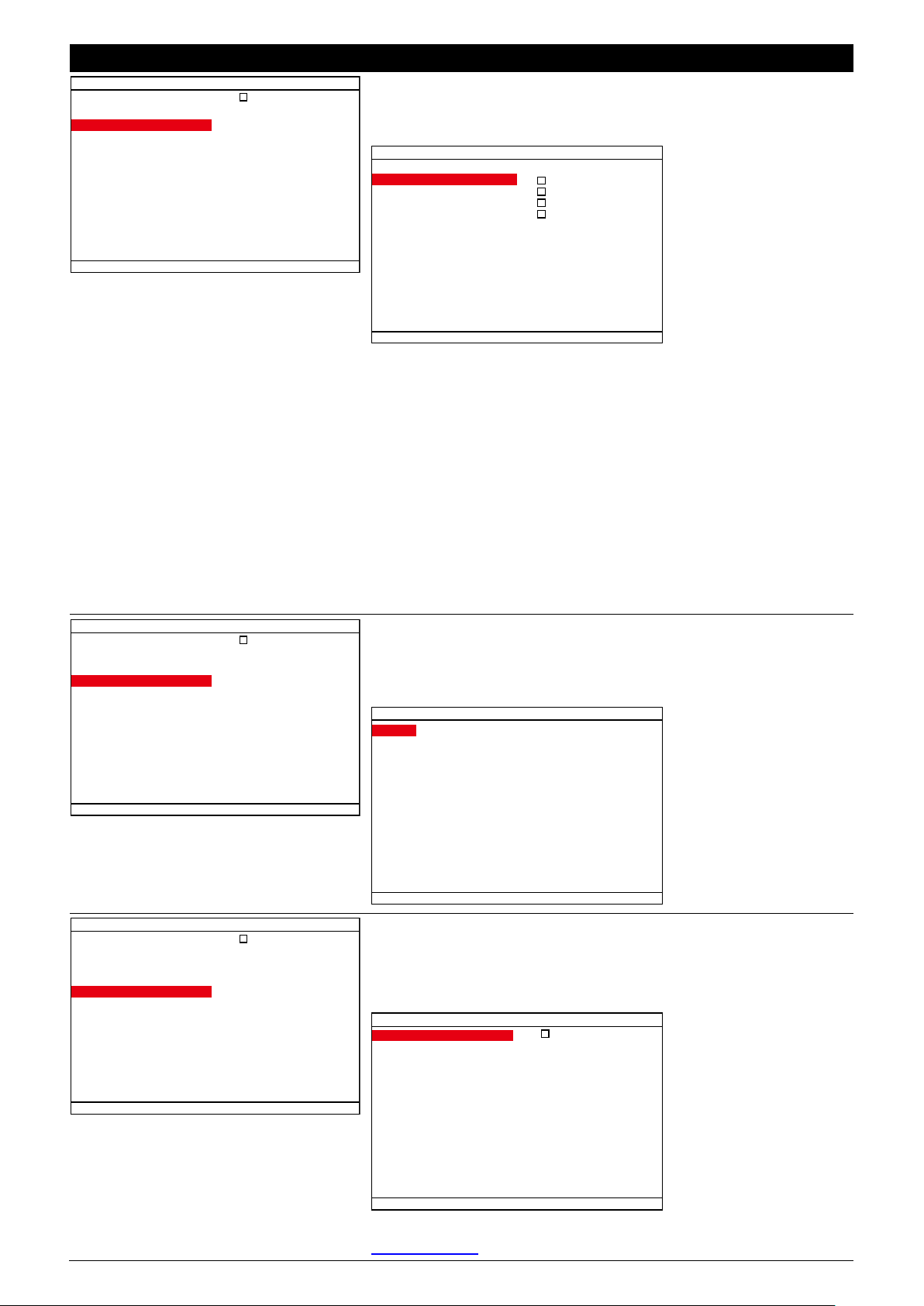
OSD MENU
Description
MISCELLANEOUS SETUP
MUTLIPLE DVR
GPS
GSM
3G
ENTERTAINMENT
GPS SETUP
To enable/disable GPS information message display on surveillance
screen.
LATITUDE
LONGITUDE
DISPLAY MESSAGE
HEADING
SPEED OVER GROUND
KM / MILE KM
GPS SETUP
LATITUDE
Enable/disable to display latitude information on surveillance screen.
LONGITUDE
Enable/disable to display longitude information on surveillance
screen.
HEADING
Enable/disable to display heading information on surveillance screen.
SPEED OVER GROUND
Enable/disable to display speed information on surveillance screen.
KM/MILE
Select the distance format – KM(kilometer) or MILE
MISCELLANEOUS SETUP
MUTLIPLE DVR
GPS
GSM
3G
ENTERTAINMENT
GSM SETUP
To setup the GSM numbers to receive the alarm message if user has
enable GSM alarming function in ALARM SETUP. Total 5 number
sets can be entered.
1
2
3
4
5
GSM NUMBER 1
GSM NUMBER 2
GSM NUMBER 3
GSM NUMBER 4
GSM NUMBER 5
00000000000000000000
00000000000000000000
00000000000000000000
00000000000000000000
00000000000000000000
GSM SETUP
MISCELLANEOUS SETUP
MUTLIPLE DVR
GPS
GSM
3G
ENTERTAINMENT
3G SETUP
Enable/disable to use 3G internet connection. After MOB DVR has
connected to the 3G service provider, the related information will be
display.
3G SETUP
ENABLE
CONNECTED NW
IP ADDRESS
SUBNET MASK
GATEWAY
SPEED
NULL
000.000.000.000
000.000.000.000
000.000.000.000
00000 Kbps
The dial number, ID, password setting of the 3G, please go to
Chapter 8.1.1.5 to setup.
58
Page 65

Chapter 4 Using the USB Playback Console
4.1 Recommended system requirements
Pentium® 4 2.4GHZ or above
Windows® 2000/ XP/Vista/7
DDR 256 MB
Graphic function must support DirectDraw
Audio card or built-in
Speaker
1 available USB2.0 port
4.2 Installing the USB Playback Console
To install the USB Playback Console:
1. Place Installation CD into the CD-ROM drive. When the installation main screen appears, click
Install USB Playback Console and then follow the on screen instructions
2. Select the language you prefer
3. Click OK to install the application
4. Click Exit to close the installation main screen.
5. You may now connect the external USB storage device that has saved recorded files to PC.
59
Page 66
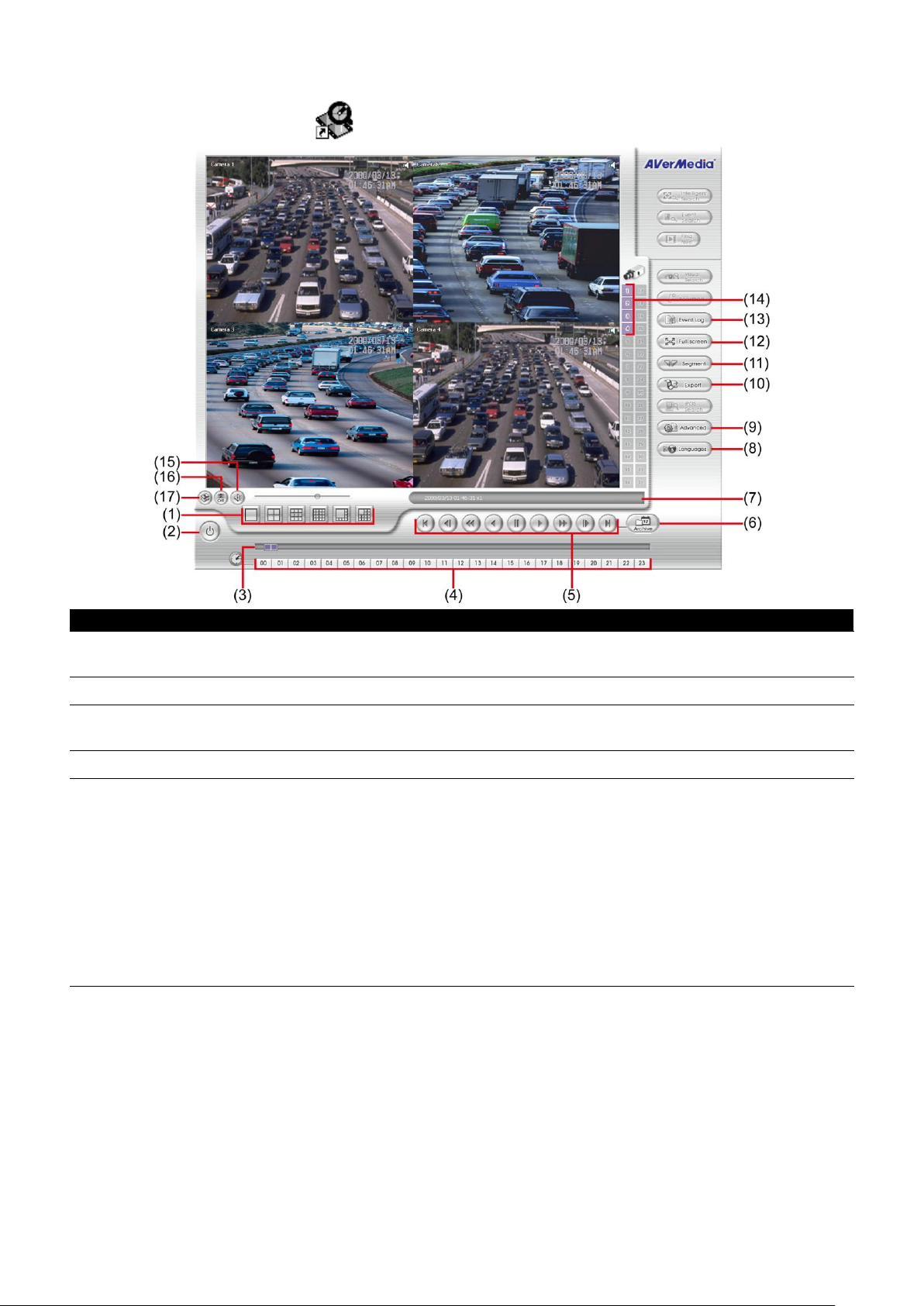
Name
Function
(1) Split Screen Mode
Select from different screen view to playback the recorded video file of the entire
camera or one camera on screen.
(2) Exit
Close the application.
(3) Progress bar
Show the progress of the file being played. You may move the bar to seek at any
location of the track.
(4) Hour button
Select and click to playback the recorded video file on the specific time frame.
(5) Playback Controller
Begin: Move at the beginning of the recorded video file.
Previous: Go back to the previous frame by frame.
Slower: Play the recorded video file at the speed of 1/2x,1/ 4x,1/8x,16x, or 1/32x
Rewind: Wind back the recorded video file.
Pause: Briefly stop playing the recorded video file.
Play: Play the recorded video file.
Faster: Play the recorded video file at the speed of 2x, 4x, 8x, 16x, or 32x.
Next: Go to the next frame by frame.
End: Go to the end of the recorded video file.
4.3 Running the USB Playback Console
To run the application, click the icon on the PC desktop
60
Page 67

Name
Function
(6) Archive
To select the video file source for playing.
- DVR Recorded File (HD): To playback the recorded video from the hard disk
which was recording video on the DVR system. (see also Chapter 4.3.2)
- Backup File(.dvr): The file is backup and save in *.dvr file format. (see also
Chapter 4.3.3)
- Backup File (.avf): The file is backup and save to external USB storage device in
*.avf format. Select the file source folder and click OK to playback.
(7) Status bar
Display the recorded date, time and play speed.
(8) Language
To switch DVR application UI language.
(9) Adv. Function
Advanced function is including :
HDD Backup: to call out HDD Backup application. (see also Chapter 5)
iEnhance: to call out iEnhance application. ( see also Chapter 7)
AVF to AVI: save *.avf file format into *.avi file format.
Realtime GPS: To view the GPS data of the DVR on the Google map.
HD Eraser: To recover the damage of recorded file (HD Eraser function doesn’t
support in MOB1304 NET).
(10) Export
Export includes Snapshot, Print, Output Video Clip, and Export KML function.
Snapshot: Capture and save the screen shot either in *.jpg or *.bmp format.
Print: Print the screen shot.
Output: Save the segmented video in *.avi format.
Export KML: Save the segmented video in *.KML format and use the Google
Earth to view the actually road direction from virtual map(see also Chapter 4.3.4)
(11) Segment
Keep a portion of the recorded video (see also Chapter 4.3.1)
(12) Full screen
Use the entire area of the screen to only display the video. To return, press the right
button of the mouse or ESC on the keyboard.
When you switch to full screen in multiple-screen mode, Left click to toggle to only
display one of the video in the multiple-screen mode or all.
(13) Event Log
To select the recorded file that listed in Event List windows.
(14) Camera ID
Show the number of cameras that are being viewed. When you are in single screen
mode, click the camera ID number to switch and view other camera.
(15) Sound /Sound bar
Turn on and off the sound
Increase and decrease the volume
Click to select
different display
mode – Map,
Hybrid, Satellite, or
terrain.
Zoom in/out the Map
Exit the
Google Map
window
61
Page 68

Name
Function
(16) De-interlace
To enhance the video quality. Set the de-interlace mode to #1, if you are capturing
motionless picture and #2, if it captures lots of movement.
(17) Watermark
- When playback *.dvr file, click watermark button to verify the correction of
playback video.
- When playback file from hard disk and *.avf file, click watermark to call out
ImageVerification application. (see also Chapter 6)
4.3.1 To Cut and Save the Portion of the Recorded Video
1. Use the Playback Control buttons or drag the bar on the playback progress bar and pause
on where you want to start the cut. Then, click Segment to set the begin mark.
2. Use the Playback Control buttons or drag the bar on the playback progress bar and pause
on where you want to end the cut. Then, click Segment to set the end mark. To cancel
segmentation, click Segment button again.
3. Click Output button to save the wanted portion.
4. In the Save As dialog box, locate on where user wants to save the file, type the filename,
and select the video format.
62
Page 69
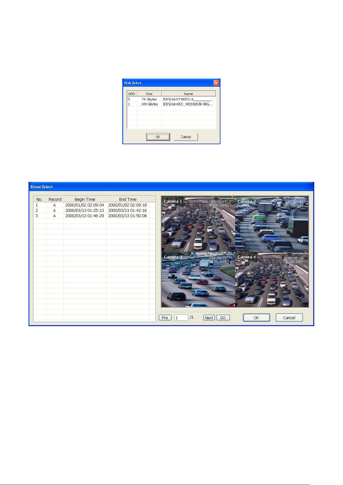
4.3.2 Playback DVR Recorded File from Hard Disk
1. Please have the hard disk which containing of recorded video data install on your PC or
using external USB enclosure to connect to your PC.
2. Click Archive button
3. Select DVR Recorded File(HD) and click OK.
4. Select the hard disk drive from Select Disk window and click OK.
5. The Event List windows will appear and list all recorded file. Select the file and preview the
selected file video. And then, click OK to start playback on UPC. To go to next page of
recorded file list, click Next. To go back to previous page, click Pre. To go to the specific
page, enter the page number and click GO.
63
Page 70
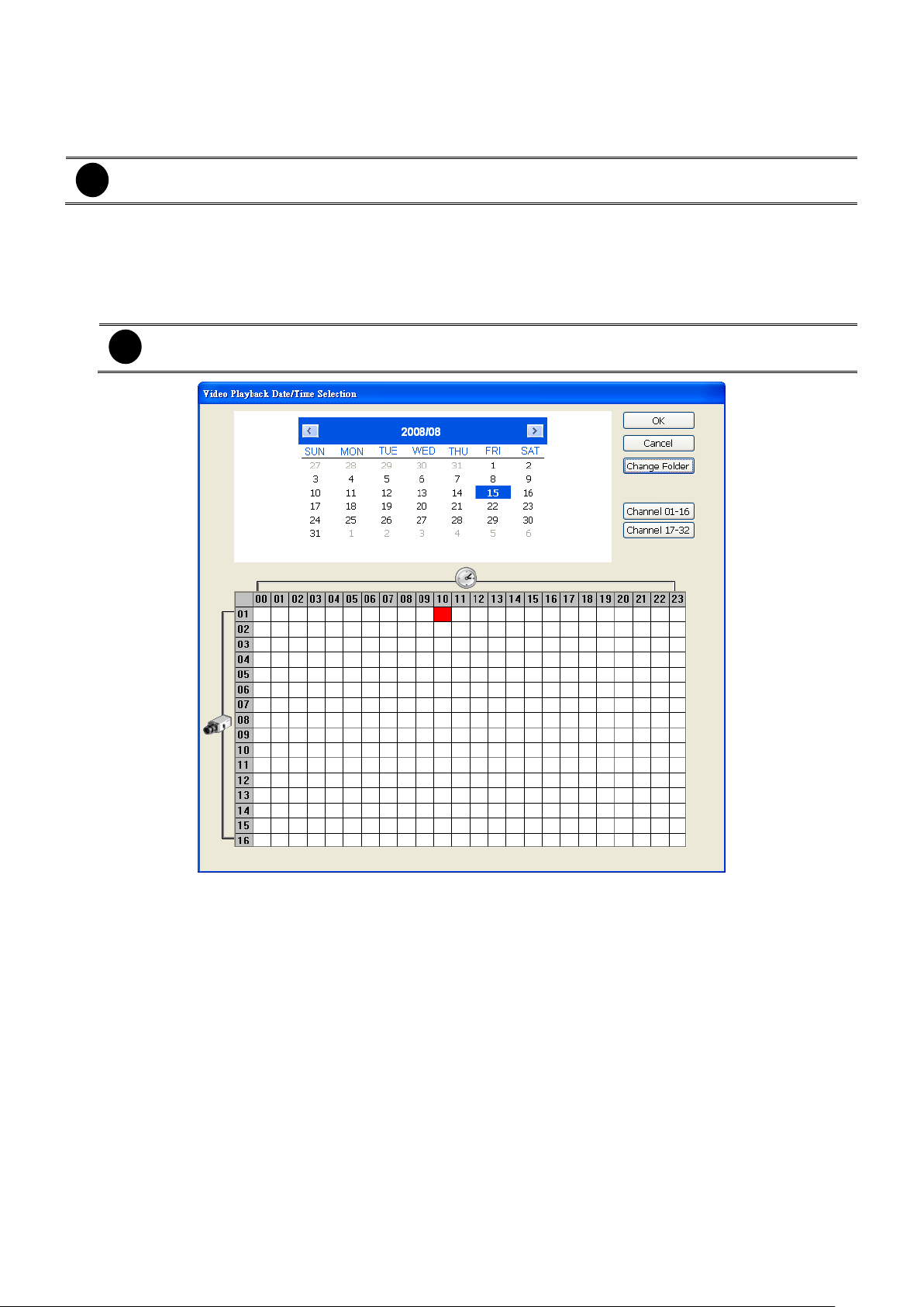
i
When open the backup video file, just locate the where backup file folder is.
i
When channels of the DVR is less than 16 channels, the Channel 01~16 and Channel 17~32
buttons are nonfunctional.
4.3.3 Playback Backup File(*.dvr)
1. Click Archive button.
2. Select Backup File(*.dvr) and click OK.
3. Locate the backup file folder and click OK.
4. Select the date on the calendar and the time from 00 to 23 to where to start playing the
recorded video file.
- Change Folder: To select different playback file form other folder location.
- Channel 01~ 16&Channel 17 ~ 32: Switch to different channel group of playback
calendar if the camera channel is more than 16 channels.
64
Page 71

i
The recorder file must contain GPS data in order to save in *.KML format and view on Google Earth.
4.3.4 View the KML File on Google Earth
1. Playback the recorded file from hard disk that is containing of recorded video data of MOB
DVR(see also Chapter 4.3.2)
2. During the playback, select a video segment that user wants to save in *.KML file format (see
also Chapter 4.3.1)
3. Click Export and select Export KML to save the video segment in *.KML format.
4. To install Google Earth, open the browser and enter http://earth.google.com. And download
the Google Earth from the web page.
5. After installed Google Earth, double click the KML file that user has saved before.
6. The Google Earth will automatically activate and load the KML file.
7. User can view the actual location of recorded file according to the GPS data that MOB DVR
has recorded.
65
Page 72
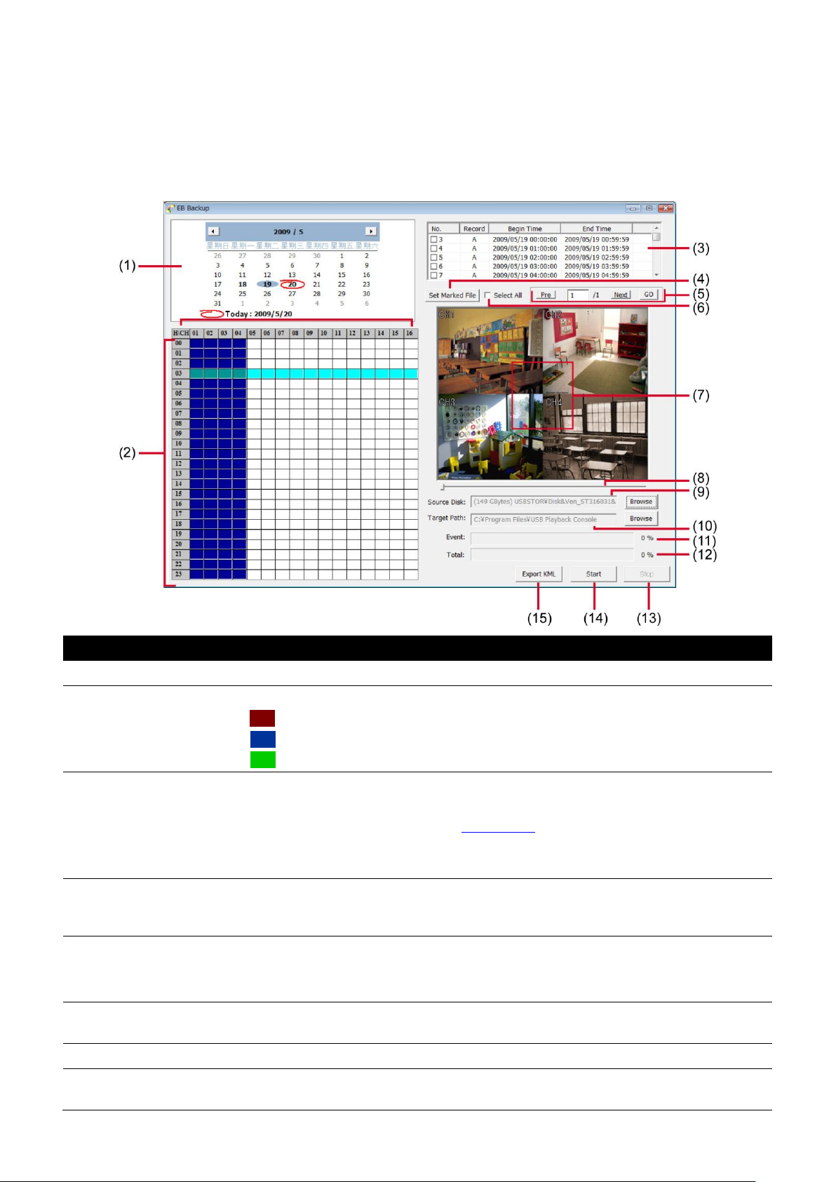
Name
Function
(1) Date
Select the date for events
(2) Hour and Channel
User can select the hour and channel for events.
: All events in this hour and channel have been selected.
: In this hour and channel has events
: Partial of events in this hour and channel has been selected.
(3) Event list
All recorded video events list
No.: the list order number
Record: the record type(see also Chapter 2.4)
Begin Time: the beginning of record time
End Time: the end of record time
(4) Set Marked File
Use Ctrl and mouse to select the multiple events from event list, and then click Set
Marked File to mark multiple events. When click Set Marked File button, the
marked event will turn to un-mark and un-mark event will turn to marked.
(5) Page Switch
Pre: go back last page
Next: go to next page
Page column: enter the page number and click Go button to go to the page
(6) Select All
Select all listed recorded video events. Click the check box again to cancel for
selecting all events.
(7) Video display
Display first frame of each recorded video channel from 4 selected.
(8) Progress bar
Show the progress of the event being played. User may move the bar to seek at
any location of the track
Chapter 5 Backup Recorded Video File
HDD Backup application provides user an interface to view recorded video from hard disk and
backup it.
5.1 Familiarizing with HDD Backup Application
66
Page 73

Name
Function
(9) Source Disk
To select the hard disk drive
(10) Target Path
To locate on where user wants to save the file
(11) Event (%)
Display the backup progress rate of event in percentage
(12) Total (%)
Display the total backup progress rate in percentage
(13) Stop
Stop backup progress
(14) Start
Start backup progress
(15) Export KML
Save the selected event files into KML file format. The export KML file can be view
on Google Earth(see also Chapter 4.3.4)
5.1.1 To Backup Recorded Video File
1. Please have the hard disk which was recording video on the DVR system install on your PC
or using external USB enclosure to connect to your PC.
2. To run the HDD Backup application, click the HDD Backup button on USB Playback
Application main interface.
3. Click Browse in Source Disk to locate the recorded video file.
4. And then, the Select Disk windows will appear as below:
5. Select the hard disk drive from Select Disk windows. All available hard disk will list on the
Select Disk windows with size and name.
6. Select the hard disk drive and click OK.
7. And then, all the recorded video files will list out.
8. Select the event which user wants to backup. Or mark the Select All to select all listed
recorded video event.
9. Locate on where user wants to save the backup file.
10. Click Start to process backup.
11. To stop the backup progress, click Stop.
12. To play the backup file, see 4.3.3.
67
Page 74

Chapter 6 ImageVerification
Image Verification is a watermark-checking program to identify the authenticity of a saved image
(e.g. by snapshot). This program can only verify uncompressed bmp image files.
6.1 To Run the ImageVerification
1. To run the ImageVerification application, click the
Application main interface.
2. In the ImageVerification screen, click Load Source Image and locate the image source.
3. Click Verify Image to begin the process.
4. Check the result in the Processed Image screen. If the picture is unmodified, the image in
the Source Image and Processed Image screen would be exactly the same. If the picture
is being modified, a warning dialog box would prompt and the modified area is highlighted.
Watermark
button on USB Playback
68
Page 75
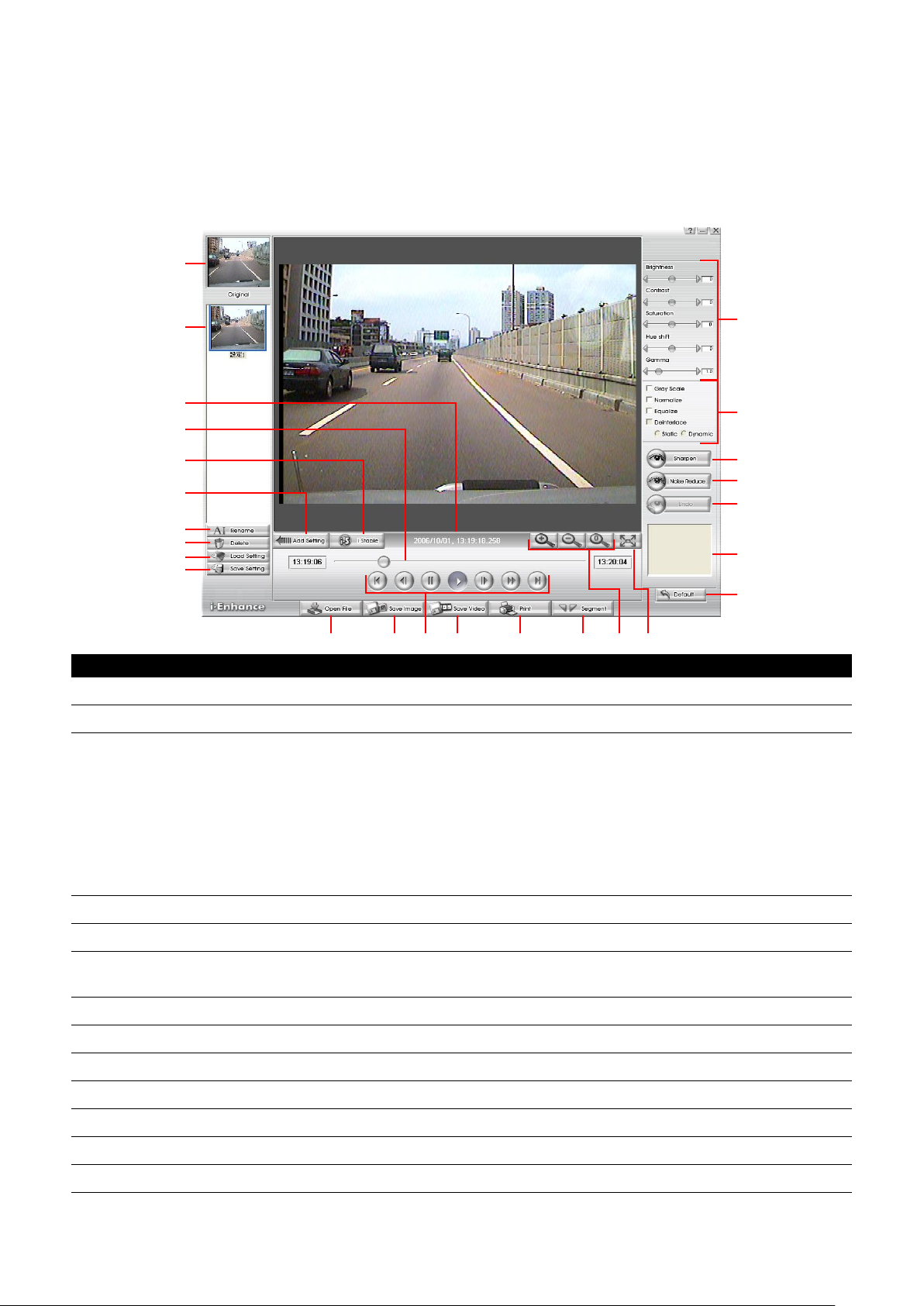
(1) (2) (4)(3) (5) (6)
(14)
(13)
(11)
(12)
(10)
(16)
(17)
(21)
(19)
(18)
(22)
(23)
(24)
(25)
(9)
(15)
(8)(7)
(20)
Name
Function
(1) Open File
Access *.dvr and *.avf video file.
(2) Save Image
Capture and save the screen shot in *.bmp format.
(3) Playback Control
Buttons
Begin: Move at the beginning of the video file.
Previous: Go back to previous frame.
Pause: Briefly stop playing the video file.
Play: Play the video file.
Faster: Play the video file at the faster speed.
Next: Go to the next frame.
End: Go to the end of the video file.
(4) Save Video
Save the edited or segmented video in *.avi format.
(5) Print
Print the screen shot.
(6) Segment
Mark the beginning and the end of the selected portion of the video. Two triangle
marks will appear on the slider. To cancel video segmentation, click this button again.
(7) Zoom Buttons
Enlarge, reduce, and set the image back to normal size.
(8) Full Screen
Use the entire screen to only display the video.
(9) Default
Set the video back to original state and delete all the changes in the history box.
(10) History Box
List all the actions.
(11) Undo
Delete the last action.
(12) Noise Reduce
Adjust the softness and repair the damaged colors.
(13) Sharpness
Improve the overall image by enhancing edges. This gives the image more depth.
Chapter 7 iEnhance
The bundled iEnhance is a video editing tool and can be used with *.dvr and *.avf video file. It
allows you to adjust the video picture quality, segment and save the selected portion of the video,
zoom in and out the image, and print or save the screen shot. You can also save the setting and
apply it on other files.
To run iEnhance application, click iEnhance button on USB Playback Console interface.
69
Page 76

Name
Function
(14) Effects
Gray Scale: convert the image into black and white (monochrome).
Normalize: adjust the brightness intensity.
Equalize: automatically adjust the images that are too dark.
De-interlace: smooth out the overlying frames.
- Static: de-interlace for motionless scene.
- Dynamic: de-interlace for moving scene.
(15) Picture
Adjustment
Adjust the Brightness, Contrast, Saturation, Hue and Gamma.
(16) Original Screen
Display the original state of the image.
(17) Temporary
Setting Block
Display the sample settings. Click the sample to apply the setting on the current
video.
(18) Status Bar
Display the date, and time of the video.
(19) Progress Bar
Show the progress of the file being played. You may move the bar to seek at any
location of the track.
(20) iStable
To reduce the jolt in the recorded video.(also see Chapter 7.1)
(21) Add Setting
Include the new setting to the temporary setting block.
(22) Rename
Change the name of the selected setting in the temporary setting block.
(23) Delete
Permanently remove the selected setting in the temporary setting block.
(24) Load Setting
Call the saved settings.
(25) Save Setting
Store the settings in the temporary setting block.
7.1 To Use iStable
The iStable function can reduce the jolt in the recorded video.
1. Click Open File button and
select the recorded video.
2. And then, click iStable button.
3. iStable windows will show up.
4. Select the smoothness level –
1(Low), 2, 3, 4, and 5(High). The
default value is 3.
5. Click Play button, and then
iStable function will start to initial
the recorded video.
6. When the initialize is done, user
will see the original and
stabilized recorded video play in
two windows. The original video
on the right side of window and
the stabilized video on the left
side of window.
70
Page 77

Chapter 8 Using the Remote Programs
User can use Microsoft Internet Explorer to access DVR system by entering the IP address. To
use this feature, make sure that your PC and DVR server both are connected to the internet and
the Network feature is enabled.
Accessing this feature for the first time you will be prompted by your browser to install
WebCamX.cab, allow the installation and you should be able to connect and login afterwards.
Click to install ActiveX if your PC required to be installed.
And then, Click Install when the Internet Explorer - Security Warning dialog box appears.
71
Page 78

i
Changing account password is strongly recommended.
After installing the WebCamX.cab and when connecting to the DVR system, you are required to
enter default account ID (default is ADMIN; case sensitive) and password (default is 111111) and
select the type of network.
72
Page 79

Name
Function
(1) DirectDraw
Enhance the video quality.
i
Not all graphic cards can support this function. If you cannot see the screen display correctly or screen is
messed, please check with VGA card vendor.
(2) Received file size
Indicate the size of the data being sent per second.
(3) Camera frames
Indicate the number of frames per second.
(4) Split screen view
Click to view one camera or all cameras on screen simultaneously.
(5) Audio
Enable/disable remote sound.
(6) Record
Start to record the video of the selected camera in AVI format. Directly click screen to
select the channel that user wants to record and press Record button.
(7) Remote Console
Initiate Remote Console. It allows you to control DVR server (see also Chapter 8.3).
(8) Remote setup
Change the DVR server settings (see also Chapter 8.1.1).
(9) PTZ Control
Initiate PTZ camera controller(see also Chapter 8.2)
(10) Snapshot
Capture and save the screen shot in *.bmp format.
(11) Full screen
Use the entire area of the screen to only display the video.
To return, Right-click or press ESC on the keyboard.
8.1 Familiarizing the WebViewer Buttons
Right-clicking on the WebViewer video screen, enables you to start video recording, switch
camera and enable/disable DirectDraw.
73
Page 80

Name
Function
(13) Select cameras to
view
Select to the view camera from different server. In Select Camera dialog box, Display
column, click to enable/disable viewing the camera.
Click Add Server and select the server type between DVR and IP Cam to add.
Click Delete Server to delete the selected item.
Click Import to load the previous saved list.
Click Export to save the list.
Click Apply All to change all the camera video quality based on the selected setting.
Click OK to exit.
74
Page 81
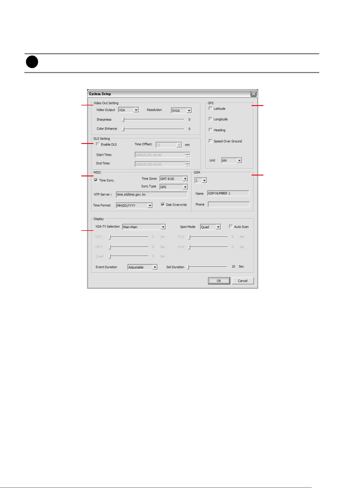
i
After changed the DVR system setting, refresh your web browser in order to apply the new setting to the
DVR system.
(1)
(2)
(3)
(4)
(5)
(6)
8.1.1 To Setup Remote System Setting
Click OK to exit and save the setting and Cancel to exit without saving the setting. The setting
here applies to Remote DVR system only.
8.1.1.1 System Setup
(1) Video Out Setting
- Video Output: Select the Video output to configure the value of Resolution, Sharpness
and Color Enhance.
- Resolution: Select the video display resolution.
- Sharpness: Adjust the sharpness of display video.
- Color Enhance: Adjust the color enhancement of display video.
(2) DLS Setting
Mark Enable DLS check box to enable daylight saving. And then, select the Start and End Time
by click setting.
- Time Offset: Assign a time that it is for daylight saving time offset in your time zone. For
example: if the time zone is in U.S. Eastern, the time offset is 1 hour.
(3) MISC
- Time Sync.: Enable/disable Network Time Protocol to adjust the time of system from the
network time server.
- Time Zone: Select the time zone of DVR located.
- Sync Type: Select the ways of the network time synchronize.
- NTP Server: Enter the URL of the network time server.
- Time Format: Select the format of time and date for the DVR system.
- Disk Overwrite: Enable/disable replacing the earliest record when the hard disk space
runs out. By default, the HDD overwrite setting is enabled
75
Page 82

(4) Display
- VGA-TV Selection: Select the VGA and TV output order.
MAIN - MAIN: Both VGA and TV output surveillance video on screen.
MAIN – SPOT: VGA output surveillance video and TV output the alarm event video.
SPOT – MAIN: VGA output alarm event video and TV output the surveillance video.
- SPOT Mode: To select the display mode (QUAD or Channel (1, 2, 3, or 4)) on spot
monitor when there is no alarm event.
- Auto scan: Enable/disable auto cycle switch to display the next channel when in full
screen mode.
- Event Duration: Select the type of event duration.
- Set Duration: Set a time gap (10 ~ 999 seconds) before switch back to preview screen
mode after display the alarm event.
(5) GPS
To enable/disable GPS information message display on surveillance screen.
- LATITUDE
Enable/disable to display latitude information on surveillance screen.
- LONGITUDE
Enable/disable to display longitude information on surveillance screen.
- HEADING
Enable/disable to display heading information on surveillance screen.
- SPEED OVER GROUND
Enable/disable to display speed information on surveillance screen.
- Unit
Select the distance format – KM(kilometer) or MILE
(6) GSM
To setup the GSM numbers for alarm inform if user has enable GSM alarming function in
ALARM SETUP. Total 5 phone number set can be entered.
- Name
Assign a name for this GSM number such as administrator‟s phone number.
- Phone
Enter the number will be receive the alarm inform when the alarm event has occurred.
76
Page 83

(1)
(2)
(3)
(4)
i
If you want to hear the voice when you playback the recorded file on this DVR, please make sure that
you have selected Audio Mute Off.
8.1.1.2 Camera Setup
(1) General
- Time Stamp
Enable/disable the time and date display on the each channel.
- Auto Record
Enable/disable auto continue recording when interrupted (i.e., power breakdown, video
playback or configuration setup). It starts to record after 10 second of idleness. This is
applicable in Always Record mode.
- Pre Record
Set the pre-recording time in seconds when alarm has occurred.
- Delay Power-OFF
Set the time for DVR system to power off self after the vehicle has turn off the engine.
(2) Camera
Select the camera and enter a name for the camera.
(3) Color Adjustment
Select the camera and adjust the Brightness, Contrast, Hue and Saturation of the selected
camera. Click Reset to Default Value to set all video setting back to the default.
(4) Audio Setting
Click Reset to Default Value to set all video setting back to the default.
- Audio Out @ Quad
Select the channel to output the audio signal While QUAD mode. Please make sure the
audio output device (such as a speaker) is connected to DVR unit.
- Audio Mute
Enable/disable to hear audio sound while playback. To hear sound, make sure the unit is
connected to a speaker.
- Volume
To adjust audio output volume.
77
Page 84

(1)
(2)
(3)
i
The channels are enabled can be set for video recording.
8.1.1.3 Record Setup
(1) Record Mode
Select D1/CIF/D1 Enhance recording mode. Under D1 mode, the video recording is in full screen
resolution and takes turns from one channel to the next one when Auto Scan enables. Each
channel is recorded up to a maximum frame rate of 30/25fps(NTSC/PAL). User can switch to
view the video in full screen or QUAD screen. Whereas in CIF mode, video recording is at a
lower resolution, but each video is recorded in 30fps/25fps (NTSC/PAL). User can switch to view
the video in full screen or QUAD screen
(2) Channel Setting
Setup parameters of each channel.
- Enable
Enable/disable the channel to display the video on the surveillance screen. If the channel
is disabling, there won‟t be any video display and recording.
- Record
Enable/disable the channel number to record video.
- Audio Record
Enable/disable audio recording. To record sound, make sure the audio input device (ex:
microphone) is connected to the DVR unit.
- Preview
Enable/disable the video preview on the surveillance screen.
- Max. FPS
Display the maximum frame rate of recording that user has set. Maximum fps total value
depends on the RESOLUTION that user has chosen.
- FPS
Set the number of frames per second to be recorded. The higher the frame rate, it uses
78
Page 85

Condition
Description
ALWAYS RECORD
Record non-stop
ALARM RECORD
Start recording when the alarm is activated. The alarm activates status according to
the setting in ALARM SETTING.
SMART RECORD
Automatically switch to recorded at the frame rate of FPS(alarm) once an alarm is
detected and if there is no motion, it records at the frame rate of FPS.
The Frame rate setting refers to CHANNEL SETTING.
VARIED RECORD
When each channel has different record schedule, the record schedule table will
display in Green color that is indicated as VARIED RECORD.
more hard disk space.
- Quality
Select the video quality setting from BEST, HIGH, GOOD, MEDIUM, NORMAL or LOW.
Choosing higher quality allows user to record less hours but the quality of the recorded
video is better.
- FPS(alarm)
Set the number of frames per second to be recorded when alarm has occurred. The
higher the frame rate, it uses more hard disk space.
- QUALITY(alarm)
Select the video quality (BEST, HIGH, GOOD, MEDIUM, NORMAL or LOW) of alarm
recording. Choosing higher quality allows user to record less hours but the quality of the
recorded video is better.
(3) Record Schedule
By default, in 24 hours, the recording schedule is set to always record every hour. Refer to the
table below to customize the recoding condition.
Select the channel to setup record schedule. Click the type of schedule and select hour (00~23)
and click OK to complete the schedule setting.
79
Page 86

(1)
(2)
(3)
(4)
(5)
(6) (7)
(8)
(9)
8.1.1.4 Alarm Setup
(1) Alarm Type
Select the way of alarming – REC, EMAIL, GSM, BUZZER, or RELAY.
(2) Alarm Continuously
Enable/disable the alarm event continuously to display on the spot monitor until the next alarm
event is coming in.
(3) Alarm Period
Set the amount of time(in seconds) to sending the alarm once triggered.
(4) Select/Deselect ALL
To enable/disable all below selection. Click Mail Setup button to setup the alarm mail sending.
- Sensor
Enable/disable to send out the alarm if sensor has been triggered according to the setting
of SENSOR SETTING.
- Motion Detection
Enable/disable to send out the alarm if motion has been detected according to the setting
of MOTION DETECTION.
- Remote Trigger
Allow user to trigger alarm from remote site.
(5) Sensor
Enable/disable initial state of the attached sensor of the channel.
(6) Motion Detection
Enable/disable the channel to detect motion.
(7) Temperature
Click Reset to Default will back to factory default value.
- Temperature Format
Select the temperature pattern display on front LCM panel.
- FAN Control
Enable/disable to setup vale of fan on/off control.
- FAN ON
80
Page 87

Set a specific temperature limit for fan active. When the hard disk temperature reaches
temperature limit, the fan will be active.
- FAN OFF
Set a specific temperature limit for fan stop. When the hard disk temperature drop to the
temperature low limit, the fan will switch to off if the fan was on.
- Alarm Threshold(High)
Set the temperature high limit (0 ~100°C) to prevent DVR unit overheating. When DVR
unit temperature reaches the high limit, the system will show the warning message or
send out alarm if the alarm is connected and set.
- Alarm Threshold(Low)
Set the temperature low limit (55 ~ 95°C) to prevent DVR unit overcooling. When DVR unit
temperature reaches the low limit, the system will show the warning message or send out
alarm if the alarm is connected and set.
- HDD Stop(High)
Set a specific temperature high (0 ~100°C) for HDD shutdown. When the hard disk
temperature reaches the temperature limit, the HDD will shutdown.
- HDD Stop(Low)
Set a specific temperature low limit (55 ~ 95°C) for HDD shutdown. When the hard disk
temperature reaches the temperature limit, the HDD will shutdown.
(8) Shock Detection
Set the value for vehicle slope detection. Click Reset to Default will back to factory default value.
(9) Voltage
- 12V Detection
Enable/disable to detect voltage for total power supply of DVR system.
- RTC(3V) Detection
Enable/disable to detect for RTC (real time clock).
- Shutdown
Enable/disable to shutdown system when the voltage threshold reaches the limit.
- Reset to Default
Set all configurations back to factory default.
81
Page 88

(1)
(2)
(3)
(4)
(5)
(6)
(7)
i
The DHCP (Dynamic Host Configuration Protocol) is a set of rules used by a communications device
(such as a computer, router or networking adaptor) to allow the device to request and get an Internet
address from a server which has a list of addresses available for assignment
8.1.1.5 Network Setup
(1) IP Mode
The system provides 3 types of IP setup mode – STATIC, DHCP, and PPPOE.
- STATIC: Assigns a constant IP address for the DVR system.
- DHCP: Assign the IP address by local DHCP server to DVR system.
- PPPOE: Point-to-Point Protocol over Ethernet is a network protocol for encapsulating PPP
frames in Ethernet frames. It is used mainly with ADSL services. If your network is using
ADSL service connecting to internet, and then, select PPPOE mode.
(2) Remote audio record
Enable/disable the audio recording at remote site.
(3) DDNS
Dynamic Domain Name Service is a data query service mainly used on the Internet for
translating domain names into Internet addresses.
- Domain Name: Enter the domain name that user has registered.
- Password: Enter the password that user has setup when registered the domain name.
(4) Wireless LAN
- SSID: SSID (Service Set Identity) is the ID assigned to the wireless AP (Access Point). Enter
the ID of the wireless AP that user wants to connect.
82
Page 89

i
Please Make sure to enable wireless function first. Please go to OSD menu and select Network >
Wireless LAN. And then, mark Enable check box and select the IP Mode.
(1)
(2)
(3)
i
- User needs to purchase the 3G USB Dongle in order to make a 3G connection. Please contact your
local dealer for purchasing of 3G USB Dongle.
- Remember to plug 3G USB Dongle into the USB port of the MOB DVR.
- Security: Select the type of encryption – WEP-64-PSK, WEP-128-PSK, WPA-TKIP-AES.
- Country Code: Then country code is depending on the regulatory region where the AP
device is sold.
(5) WLAN IP Setting
- ENABLE
Enable/disable the wireless function.
- IP MODE
Select the IP mode of wireless – STATIC or DHCP.
STATIC: Assigns a constant IP address for the DVR system.
DHCP: Assign the IP address by local DHCP server to DVR system.
(6) Stream Setup
Click it to setup each channel stream and quality for the remote site viewing.
(1) Enable
Enable/disable the channel. If channel is disabled, the video stream will not been seen in remote site
and transmitting to remote site.
(2) Network Stream FPS
Set the stream FPS of channel. Scroll the bar to adjust the fps.
(3) Quality
Select the quality of the channel.
(7) 3G Setup
Setup parameters of the 3G. The following parameters are provided by
user‟s 3G service provider when user apply 3G service.
- Dial ON: Enable/disable auto dial function.
- APN: The name used to identify a GPRS bearer service in the
GSM mobile network.
- Number: Enter the number for dialing to your 3G service provider.
- User ID: Enter the ID for accessing authentication.
- Password: Enter the password for accessing authentication.
- Connected NW: The network that you has connected will be
shown after 3G connection is successful.
- IP: The IP address is assigned by your 3G service provider after
3G connection is successful.
83
Page 90

8.1.1.6 User Setup
To change Admin, operator, and user account‟s password. Enter the new password in Password
and re-enter again in Password Confirm. Click OK to complete the change.
84
Page 91

Name
Function
(1) Direction buttons
Adjust and position the focal point of the PTZ camera. Click the center to pan
automatically.
(2) Zoom +/-
Zoom in and out the image.
(3) Select PTZ
Choose to enable/disable the PTZ camera. In the Select PTZ dialog box, Select column,
click to enable/disable viewing and controlling the PTZ camera.
Click OK to exit and save the setting and Cancel to exit without saving the setting.
(4) Focus +/-
Adjust the focus manually to produce clear image.
(5) Auto Pan Groups
Operate the PTZ cameras automatically based on the selected camera group preset
position number.
(6) Camera preset
position number
Move the PTZ camera to the preset point. The reset point (1~9) is based on the user has
setup by remote control at local site.
8.2 Familiarizing the WebViewer PTZ Buttons
85
Page 92

i
Right-click on the screen can enable GPS function (see also Chapter 2.4.3) if the remote MOB DVR
server has installed the GPS device and enabled the GPS function.
Name
Function
(1) Exit
Close/minimize remote console application
(2) Split Screen Mode
Select from 2 different split screen type to playback the recorded video file of all the
cameras or one camera on the screen.
(3) Record
Start/stop video recording.
(4) Network
Enable/disable remote system access. This feature allows you to access DVR
server from a remote location via internet connection.
(5) Setup
Configure the Remote Console setting. (see also Chapter 7.2.1)
(6) PTZ
To call out PTZ control panel for controlling PTZ camera.
(7) Preview
Switch to Preview/Playback mode. This allows you to view live camera display.
(8) Playback
Switch to Playback mode. This allows you to view the recorded video file. (see also
Chapter 7.4)
(9) Status Bar
Display the current date, time and hard disk free space.
(10) Camera ID
Show the number of cameras that are being viewed. When you are in single screen
mode, click the camera ID number to switch and view other camera.
(11) Snapshot
Capture and save the screen shot either in *.jpg or *.bmp format.
(12) Auto Scan
Enable/disable channel auto cycle switch.
(13) Full screen
Use the entire area of the screen to only display the video.
To return, Right click the mouse or press ESC on the keyboard.
(14) Audio
Enable/disable the sound display
(15) DirectDraw
Enhance the video quality.
i
Direct Draw function supports for certain VGA card. For more information, please contact your VGA card
vendor.
8.3 Familiarizing the Remote Console Buttons
86
Page 93

(1)
(2)
(3)
(4)
i
To add network storage, the Internet storage drive/folder must be mapped as Network Driver in DVR
server. To know how to assign or connect to a network drive, please refer to your Windows help file and
search “Map Network drive”.
8.3.1 To Setup Remote Console Setting
Click Setup button to call out the System Setting windows. Click OK to exit and save the setting
and Cancel to exit without saving the setting.
(1) Storage Path
Set the directory on where to save the data. When there is not enough free space to record one
hour data, the system automatically replaces the oldest data. In case you have more than one
storage path, the system automatically saves the data to the next storage path. By default the
data is stored in C:\RemoteData, to insert another storage path, click Add. To remove the
selected path, click Delete.
- Enable network storage
Select the Enable network storage check box to send the recorded video in network attached
storage.
(2) Language
Customize the system to display the tool tips and dialogs based on the selected language. By
default the language is in English.
(3) Remote Server
Enter the DVR Server IP and Server Port number that user wants to remote connect it.
(4) Channel Settings
The numbers from 01 to 04 represent the camera ID. In Transmitting Channels section, enable
the camera number to receive the camera signal from the server. In Visible Channels section,
enable the camera number to view the camera signal on Remote Console screen. To select all
the cameras, enable the ALL check box.
87
Page 94

88
Page 95

8.4 Using the Remote Playback
To use this feature, first switch to playback mode by clicking the Playback icon, and then, select
the source of the file. In the Select Playback Mode dialog box, choose Local Playback to open
the file that is recorded in the Remote Console, and Remote Playback to open the file that is
recorded on the DVR server.
Click OK to proceed and Cancel to void this operation.
In the Remote Playback Date/Time Selection, the number from 00 to 23 represent the time in
24-hour clock. The numbers from 01 to 04 represent the camera number.
To Make a Selection:
1. Select the date in the calendar. Use and buttons to shift the calendar to the left or
right.
2. In the table below, click on the blue block to select and open the recorded file. The blue block
turns red when it is selected. The block that appears in white doesn‟t have data. You can only
select one block when you choose Download and Playback.
3. Click OK to proceed and Cancel to void this operation.
4. The system divides the selected hour into 16 video thumbnails. In the Time Selection screen,
click on the video thumbnail you want to download (see also Chapter 8.4.3).
89
Page 96

90
Page 97

Name
Function
(1) Exit
Click to exit or minimize the application. The password is required for exit or minimize.
(2) Progress bar
Show the progress of the file being played. You may move the bar to seek at any
location of the track.
(3) Split Screen Mode
Select from 6 different split screen type to playback the recorded video file of all the
cameras, or one camera over the other or alongside on a single screen.
i
- If there are only 4 cameras, you won‟t be able to switch to 16, and 13 split screen mode.
- To zoom in an area on the screen, Right click and Drag a square on the area you want to enlarge. To
back to normal view, right click the channel screen again.
(4) Hour Buttons
Select and click to playback the recorded video file on the specific time frame.
i
The Hour buttons represent the time in 24-hour clock. The blue bar on top of the hour button indicates
that there is a recorded video file on that period of time. If there is no recorded data within the hour, there
will be no color bar on top of the hour button. While the red bar indicates that you are currently viewing
the recorded video file.
(5) Playback Control
Buttons
Begin: Move at the beginning of the recorded video file.
Previous: Go back to the previous frame.
Slower: Play the recorded video file at the speed of 1/2x, 1/4x, 1/8x, or 1/16x.
Rewind: Wind back the video file.
Pause: Briefly stop playing the recorded video file.
Play: Play the recorded video file.
Faster: Play the recorded video file at the speed of 2x, 4x, 8x, 16x or 32x.
Next: Go to the next frame.
End: Go to the end of the video file.
8.4.1 Familiarizing the Local Playback Buttons
91
Page 98

Name
Function
(6) Archive
Select the date on the calendar and the time from 00 to 23 to where to start playing the
recorded video file.
- Also, user can open the recorded file from certain location by click OPEN FILE
button
- Click Channel 01~ 16 and Channel 17 ~ 32 button to switch to different channel
group of playback calendar if the DVR has more than 16 channels.
- Mark Day Light Saving, the playback calendar will show the available playback
records during day light saving period.
i
The numbers from 00 to 23 represent the time in 24-hour clock. The numbers from 01 to 16 represent the
camera ID. While the red colored column indicates on where to start playing the recorded video file. If
there is no any video data, it will be no color bar on top of the date button.
(7) Preview
Switch to Preview mode.
(8) Playback
Switch to Playback mode. This allows you to view the recorded video file.
(9) Status bar
Display the record date, time, HDD capacity in preview mode and play speed in
playback mode.
(10) Camera ID
Show the number of cameras that are being viewed. When you are in single screen
mode, click the camera ID number to switch and view other camera.
(11) Export
Export includes Snapshot, Print, and Output function.
Snapshot: Capture and save the screen shot either in *.jpg or *.bmp format.
Print: Print the screen shot.
Output: Save the segmented file in *.avi format
(12) Segment
Keep a portion of the recorded video you want (see also Chapter 8.4.1.1).
(13) Full screen
View in Playback-compact mode. To return, press the right button of the mouse or ESC
on the keyboard.
(14) Event Log
Show the record of activities that take place in the system. To filter the records, select
and click the option button to only display Event, System, Operation, Network or POS.
(15) Visual Search
Search from a specific camera by Date, Hour, Minute, 10 Seconds and Second. (See
also Chapter 8.4.1.2)
(16) Find Next
Search for the next event or changes in the motion detector frame. You can use this
when you are using Intelligent Search or Event Search function.
(17) Intelligent Search
Search the changes in the motion detector frame (See also Chapter 8.4.1.3).
(18) Audio
Enable/disable audio play
(19) De-interlace
To enhance the video quality. Set the de-interlace mode to #1, if you are capturing
motionless picture and #2, if it captures lots of movement.
92
Page 99
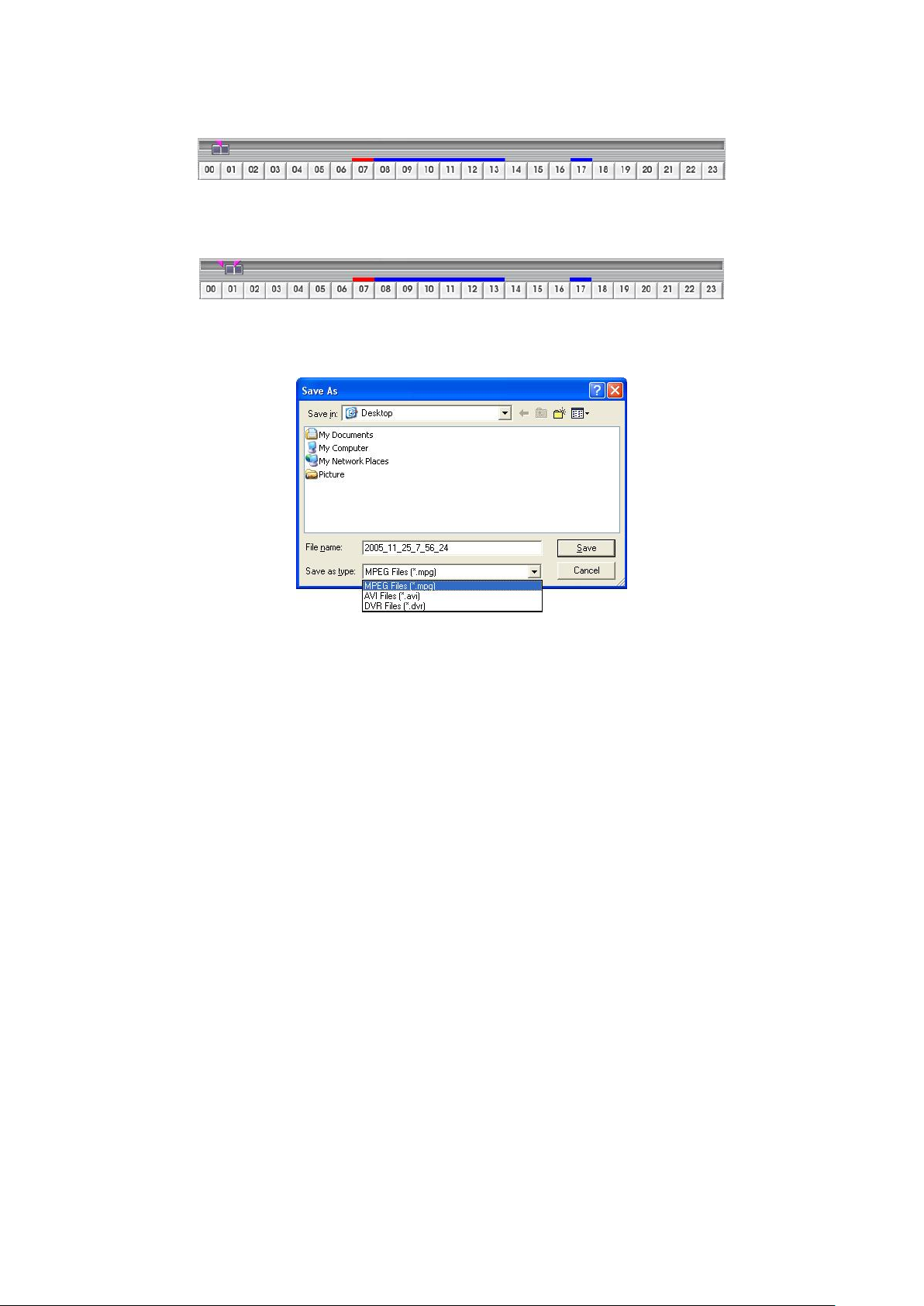
8.4.1.1 To Cut and Save the Wanted Portion of the Recorded Video
1. Use the Playback Control buttons or drag the bar on the playback progress bar and pause on
where you want to start the cut. Then, click Segment to set the begin mark.
2. Use the Playback Control buttons or drag the bar on the playback progress bar and pause on
where you want to end the cut. Then, click Segment to set the end mark. To cancel
segmentation or set the segment marks from the start, click Segment button again.
3. Click Export >> Output button to save the wanted clip.
4. In the Save As dialog box, locate on where you want to save the file, type the filename, and
select the video format.
93
Page 100
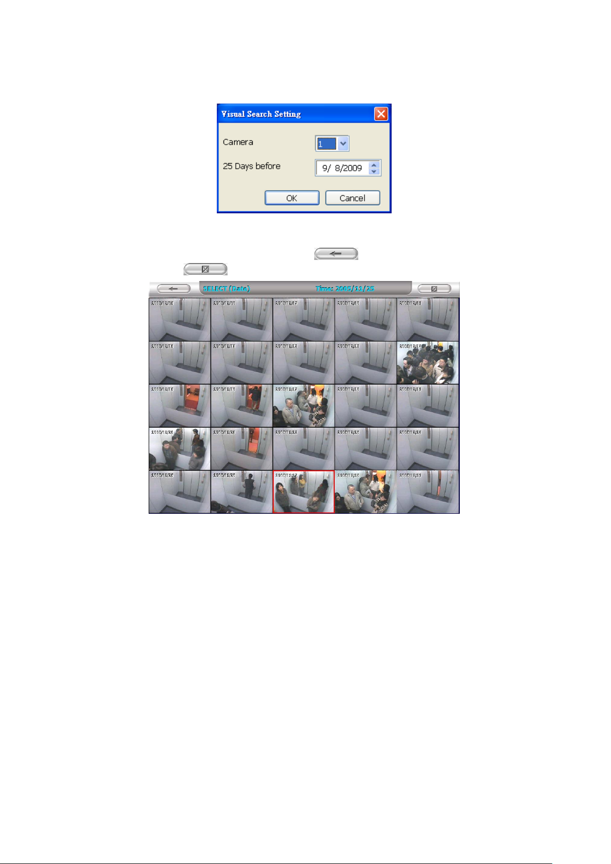
8.4.1.2 To Search Using the Visual Search
1. Click Visual Search.
2. In the Visual Search Setting dialog box, select the Camera number and the date. Then click
OK.
3. When a series of frames appear by date, click on the frame to display another series of frames and
search by every Hour of that date, every 3Minutes of that hour, every 10 Seconds of that minute,
every Second of that 10 seconds. To go back, click . To view from the selected frame and
close event search, click .
94
 Loading...