

Avdel 7265 Instruction Manual
Hydro-Pneumatic Power Tool
07265
07265
I n s t r u c t i o n M a n u a l
Pass onto user to read and keep for reference

AIR PRESSURE Minimum - Maximum 5 - 7 bar 70 - 100 lbf/in
2
FREE AIR VOLUME REQUIRED @ 5.5 bar / 80 lbf/in
2
3.5 litres .12 ft
3
STROKE Minimum 26.2 mm 1.03 in
PULL FORCE @ 5 bar / 70 lbf/in
2
15 kN 3350 lbf
CYCLE TIME Approximately 1.7 seconds
NOISE LEVEL Less than 70 dB(A)
PISTOL WEIGHT 3.1 kg 6.82 lb
TOTAL WEIGHT Pistol & Intensifier 37 kg 81.4 lb
VIBRATION Less than 2.5 m/s
2
8 ft/s
2
S P E C I F I C A T I O N S F O R 0 7 2 6 5 T O O L
■
■
■
■
■
■
■
■
■
■
■
■
■
■
■
■
■
■
■
■
■
■
■
■
■
AVDEL policy is one of continuous development. Specifications shown in this document may be subject to changes which
may be introduced after publication. For the latest information always consult Avdel.

S A F E T Y
I N T E N T O F U S E
P U T T I N G I N T O S E R V I C E
N O S E A S S E M B L I E S
S E R V I C I N G
P R I M I N G
F A U L T D I A G N O S I S
General 2
Specific to Type of Tool 3
General 4
07265 Tool Dimensions / Selection 4-5
Air Supply 6
Operating Procedure 6
Accessories 7-8
07265 Fitting/Servicing/Components 10-11
Regular Servicing - Service Kit 12
Maintenance 13-15
General Assembly & Parts List 16-21
Priming Oil Details 22
Priming Procedure 22
Fault Diagnosis Table 23
C
O N T E N T S
1

S
A F E T Y
2
This instruction manual must be read with particular attention to the following safety rules,
by any person installing, operating, or servicing this tool.
DO NOT USE OUTSIDE THE DESIGN INTENT.
DO NOT USE EQUIPMENT WITH THIS TOOL/MACHINE OTHER THAN THAT
RECOMMENDED AND SUPPLIED BY AVDEL.
ANY MODIFICATION UNDERTAKEN BY THE CUSTOMER TO THE TOOL/MACHINE,
NOSE ASSEMBLIES, ACCESSORIES OR ANY EQUIPMENT SUPPLIED BY AVDEL OR THEIR
REPRESENTATIVES, SHALL BE THE CUSTOMER'S ENTIRE RESPONSIBILITY. AVDEL WILL BE
PLEASED TO ADVISE UPON ANY PROPOSED MODIFICATION.
THE TOOL/MACHINE MUST BE MAINTAINED IN A SAFE WORKING CONDITION AT
ALL TIMES AND EXAMINED AT REGULAR INTERVALS FOR DAMAGE AND FUNCTION BY
TRAINED COMPETENT PERSONNEL. ANY DISMANTLING PROCEDURE SHALL BE
UNDERTAKEN ONLY BY PERSONNEL TRAINED IN AVDEL PROCEDURES. DO NOT DISMANTLE
THIS TOOL/MACHINE WITHOUT PRIOR REFERENCE TO THE MAINTENANCE INSTRUCTIONS.
CONTACT AVDEL WITH YOUR TRAINING REQUIREMENTS.
THE TOOL/MACHINE SHALL AT ALL TIMES BE OPERATED IN ACCORDANCE WITH
RELEVANT HEALTH AND SAFETY LEGISLATION. IN THE U.K. THE “HEALTH AND SAFETY AT
WORK ETC. ACT 1974” APPLIES. ANY QUESTION REGARDING THE CORRECT OPERATION
OF THE TOOL/MACHINE AND OPERATOR SAFETY SHOULD BE DIRECTED TO AVDEL.
THE PRECAUTIONS TO BE OBSERVED WHEN USING THIS TOOL/MACHINE MUST BE
EXPLAINED BY THE CUSTOMER TO ALL OPERATORS.
ALWAYS DISCONNECT THE AIRLINE FROM THE TOOL/MACHINE INLET BEFORE
ATTEMPTING TO ADJUST, FIT OR REMOVE A NOSE ASSEMBLY.
DO NOT OPERATE A TOOL/MACHINE THAT IS DIRECTED TOWARDS ANY PERSON(S).
ALWAYS ADOPT A FIRM FOOTING OR A STABLE POSITION BEFORE OPERATING THE
TOOL/MACHINE.
ENSURE THAT VENT HOLES DO NOT BECOME BLOCKED OR COVERED AND THAT
HOSES ARE ALWAYS IN GOOD CONDITION.

3
In addition to the general safety rules opposite, the following specific safety points must also
be observed:
THE OPERATING PRESSURE SHALL NOT EXCEED 7 BAR - 100 LBF/IN2.
DO NOT OPERATE THE TOOL WITHOUT FULL NOSE EQUIPMENT IN PLACE.
CARE SHALL BE TAKEN TO ENSURE THAT SPENT STEMS ARE NOT ALLOWED TO
CREATE A HAZARD.
THE TOOL MUST BE FITTED WITH AN UNDAMAGED PINTAIL DEFLECTOR OR STEM
CATCHER BEFORE OPERATING.
IF THE TOOL IS FITTED WITH A PINTAIL DEFLECTOR AND IS USED IN THE VERTICAL
NOSE DOWNWARD POSITION, THE PINTAIL DEFLECTOR SHOULD BE ROTATED UNTIL THE
APERTURE IS FACING AWAY FROM THE OPERATOR AND OTHER PERSON(S) WORKING IN
THE VICINITY.
WHEN USING THE TOOL, THE WEARING OF SAFETY GLASSES IS REQUIRED BOTH BY
THE OPERATOR AND OTHERS IN THE VICINITY TO PROTECT AGAINST RIVET EJECTION,
SHOULD A FASTENER BE PLACED ‘IN AIR’. WE RECOMMEND WEARING GLOVES IF THERE
ARE SHARP EDGES OR CORNERS ON THE APPLICATION.
TAKE CARE TO AVOID ENTANGLEMENT OF LOOSE CLOTHES, TIES, LONG HAIR,
CLEANING RAGS ETC. IN THE MOVING PARTS OF THE TOOL WHICH SHOULD BE KEPT DRY
AND CLEAN FOR BEST POSSIBLE GRIP.
WHEN CARRYING THE TOOL FROM PLACE TO PLACE KEEP HANDS AWAY FROM THE
TRIGGER/LEVER TO AVOID INADVERTENT START UP.
EXCESSIVE CONTACT WITH HYDRAULIC OIL SHOULD BE AVOIDED. TO MINIMIZE THE
POSSIBILITY OF RASHES, CARE SHOULD BE TAKEN TO WASH THOROUGHLY.

The hydro-pneumatic 07265 tool is designed to place Avdel breakstem rivets at high speed making it ideal for batch or flow-line
assembly in a wide variety of applications throughout all industries.
The 07265 is of the remote intensifier or split tool concept, (see page 5).
Pistol Grip type head fitted with a stem catcher is the standard tool for which a stem deflector is available (see details page 9). It is also
possible to order the base tool only (part number 07265-00300) which will not be fitted with a nose assembly.
4
I
N T E N T O F U S E
Steel
Al. Alloy
Al. Alloy
Al. Alloy
Al. Alloy
Al. Alloy
Al. Alloy
Al. Alloy
Al. Alloy
Al. Alloy
Steel
St. Steel
Al. Alloy
Steel
St. Steel
Al. Alloy
Steel
St. Steel
St. Steel
Al. Alloy
Al. Alloy
Steel
Al. Alloy
Steel
Al. Alloy
Steel
AVEX
Snap Head
TLR
AVSEAL
MONOBOLT
Protruding Head
& 100˚ csk
*
The nose tip actually
remains the same, it is
the nose casing that is
longer.
See nose assemblies on
page 10 for details.
AVINOX BE61
AVTAINER
MAXLOK
Brazier Head
& 90˚ csk
HEMLOK
Protruding Head
3
/16"
3
/16"
1
/4"
8mm
9mm
10mm
3
/16"
1
/4"
3
/16"
3
/8"
3
/16"
1
/4"
1
/4"
07265-00030
07265-00008
07265-00010
07265-00040
07265-00045
07265-00041
07265-00046
07265-00042
07265-00047
07265-00012
07265-00012
07265-00012
07265-00014
07265-00014
07265-00014
07265-00016
07265-00016
07265-00016
07265-00036
07265-00006
07265-00001
07265-00001
07265-00002
07265-00002
07265-00004
07265-00004
07381-04800
07498-02000
07498-01100
07340-08000
07498-08800
07340-08100
07498-08900
07340-08200
07498-09000
07498-04700
07498-04700
07498-04700
07498-04600
07498-04600
07498-04600
07498-00500 *
07498-00500 *
07498-00500 *
07347-03700
07498-00700
07610-02000
07610-02000
07610-02100
07610-02100
07612-02000
07612-02000
07265 TOOL SELECTION
FASTENER
NOSE (see drawing above for A & B)
MATERIAL/
DETAIL
Ø COMPLETE
TOOL PART Nº
NOSE ASSY
PART Nº
-
-
-
-
-
-
-
-
-
-
-
-
-
-
-
-
-
-
-
07265-02900
07265-02900
07265-02900
07265-02900
-
-
ADAPTOR
PART Nº
NAME &
HEAD
Standard
Standard
Standard
Standard
Extended
Standard
Extended
Standard
Extended
Standard
Standard
Standard
Standard
Standard
Standard
Extended *
Extended *
Extended *
Standard
Standard
Standard
Standard
Standard
Standard
Standard
Standard
.13
.16
.156
.22
.285
.22
.285
.22
.285
.16
.16
.16
.156
.156
.156
.156
.156
.156
.13
.16
.14
.14
.14
.14
.14
.14
A
(in)
2.4
2.4
3.6
3.9
3.9
3.9
3.9
3.9
3.9
2.4
2.4
2.4
2.4
2.4
2.4
3.9
3.9
3.9
2.4
7.4
2.0
2.0
2.1
2.1
2.4
2.4
B
(in)
3.3
4.1
4.0
5.6
7.2
5.6
7.2
5.6
7.2
4.1
4.1
4.1
4.0
4.0
4.0
4.0
4.0
4.0
3.3
4.1
3.6
3.6
3.6
3.6
3.6
3.6
A
(mm)
61
61
99
99
99
99
99
99
99
61
61
61
61
61
61
99
99
99
61
188
51
51
53
53
61
61
B
(mm)
NOSE TIP
TYPE
07265
B
A
6.5
160
1.35
34
5.15
130
500
19.7
400
15.75
25
0
9.85
5000
197
5
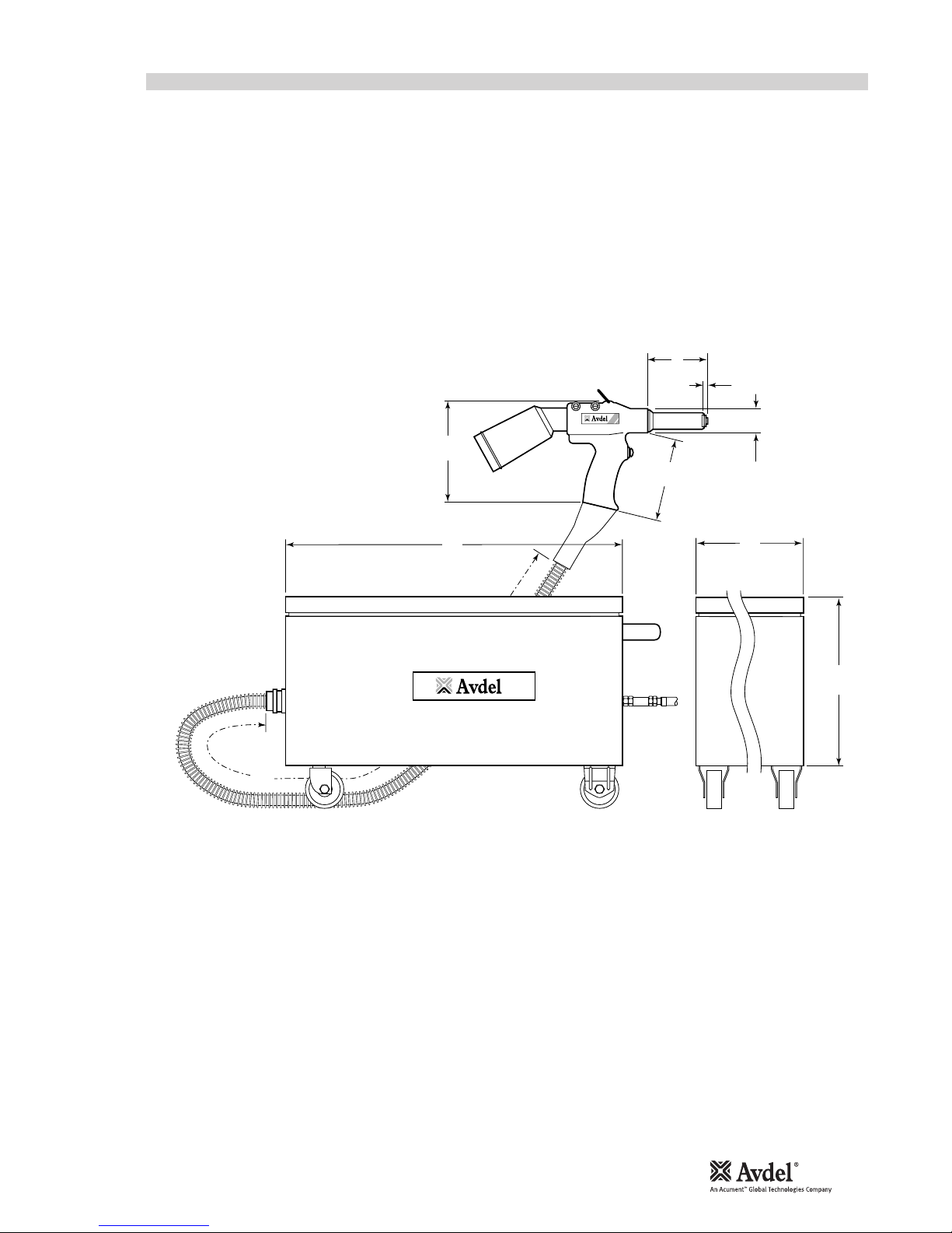
07265 - TOOL DIMENSIONS
Features include an on/off switch for a vacuum facility and an adjustable air restrictor to control the amount of vacuum according to
which fastener is being used.
Spent stems are collected in a stem catcher.
The vacuum is also used to retain fastener in the nose tip prior to its installation.
Dimensions shown in bold are millimetres.
Other dimensions are in inches.

O P E R A T I N G P R O C E D U R E
OPTION 1
Ensure that the correct nose equipment is fitted.
Connect the tool to the air supply.
Insert the fastener body squarely into the prepared hole of the
application.
Apply the tool to the protruding fastener stem.
Fully operate the trigger. The tool cycle will ensure the fastener
is placed.
Check that stems are projected into the stem catcher unit. If not
refer to the vacuum stem extraction valve paragraph on page
14 in the Maintainence section.
8
6
4
2
0
10
12
14
16
TAKE OFF POINT
FROM MAIN SUPPLY
STOP COCK
(USED DURING MAINTENANCE
OF FILTER/REGULATOR
OR LUBRICATION UNITS)
MAIN SUPPLY
DRAIN POINT
PRESSURE REGULATOR
AND FILTER
(DRAIN DAILY)
LUBRICATOR
3
M
E
T
R
E
S
M
A
X
I
M
U
M
0
7
2
6
5
6
P
U T T I N G I N T O S E R V I C E
A I R S U P P L Y
All tools are operated with compressed air at an optimum pressure of 5.5 bar. We recommend the use of pressure regulators and
automatic oiling/filtering systems on the main air supply. These should be fitted within 3 metres of the tool (see diagram below) to ensure
maximum tool life and minimum tool maintenance.
Air supply hoses should have a minimum working effective pressure rating of 150% of the maximum pressure produced in the system
or 10 bar, whichever is the highest. Air hoses should be oil resistant, have an abrasion resistant exterior and should be armoured where
operating conditions may result in hoses being damaged. All air hoses MUST have a minimum bore diameter of 6.4 millimetres or 1/4 inch.
Read servicing daily details page 10.
■
■
■
■
■
■
■
■
■
■
■
■
OPTION 2
Ensure that the correct nose equipment is fitted.
Connect the tool to the air supply.
Insert the fastener stem into the nose of the tool.
Insert the tool with the fastener squarely into the prepared hole
of the application.
Fully operate the trigger. The tool cycle will ensure the fastener
is placed.
Check that stems are projected into the stem catcher unit. If not
refer to the vacuum stem extraction valve paragraph on page
14 in the Maintainence section.
 Loading...