

Avdel 07265 Instruction Manual

07265
07265
Hydro-Pneumatic Power Tool
Instruction Manual
Original Instruction


3
Safety Rules 4
Specifications
Tool Specification 5
Tool Dimensions 5
Intent of Use
Tool Selection 6
Putting into Service
Air Supply 7
Operating Procedure 7
Accessories
Handling and Holster Kit 8
Pin Tail Deflector 8
Quick Connect Kit 9
Nose Assemblies
Fitting Instructions 10
Fitting Instructions for Maxlok®Nose Assemblies 10
Servicing Instructions 11
07285 Nose Assembly Components 11
Servicing the Tool
Daily 12
Weekly 12
Moly Lithium Grease EP 3753 Safety Data 12
Service Kit 12
Maintenance 13
Stem Catcher Unit 13
Piston Assembly 13
Trigger Assembly 14
Vacuum Stem Extraction Switch 14
Cabinet 14
Intensifier 14
Pilot Valve 15
Pressure Regulator and Filtering assembly 15
Air Pressure Indicator Assembly 15
Contents
LIMITED WARRANTY
Avdel makes the limited warranty that its products will be free of defects in workmanship and materials
which occur under normal operating conditions. This Limited Warranty is contingent upon: (1) the product
being installed, maintained and operated in accordance with product literature and instructions, and (2)
confirmation by Avdel of such defect, upon inspection and testing. Avdel makes the foregoing limited
warranty for a period of twelve (12) months following Avdel’s delivery of the product to the direct purchaser
from Avdel. In the event of any breach of the foregoing warranty, the sole remedy shall be to return the
defective Goods for replacement or refund for the purchase price at Avdel’s option. THE FOREGOING
EXPRESS LIMITED WARRANTY AND REMEDY ARE EXCLUSIVE AND ARE IN LIEU OF ALL OTHER WARRANTIES
AND REMEDIES. ANY IMPLIED WARRANTY AS TO QUALITY, FITNESS FOR PURPOSE, OR MERCHANTABILITY
ARE HEREBY SPECIFICALLY DISCLAIMED AND EXCLUDED BY AVDEL.
Avdel UK Limited policy is one of continuous product development and improvement and we reserve the right to change the specification of any product without prior notice.
General Assembly of Base Tool
General Assembly of Handle Tool 07285-03000 16
Parts List for 07285-03000 17
General Assembly of Cabinet 07265-03200 18
Parts List of Cabinet 07265-03200 19
General Assembly of Intensifier 07005-01650 20
Parts List of Intensifier 07005-01650 20
General Assembly of Valve 07005-00590 21
Parts List of Valve 07005-00590 21
Priming
Oil Details 22
Hyspin®VG32 Oil Safety Data 22
Priming Procedure 23
Fault Diagnosis
Symptom, Possible Cause and Remedy 24

4
Safety Rules
1 Do not use outside the design intent.
2 Do not use equipment with this tool/machine other than that recommended and supplied by Avdel UK Limited.
3 Any modification undertaken by the customer to the tool/machine, nose assemblies, accessories or any equipment supplied by
Avdel UK Limited or their representatives, shall be the customer’s entire responsibility. Avdel UK Limited will be pleased to advise
upon any proposed modification.
4 The tool/machine must be maintained in a safe working condition at all times and examined at regular intervals for damage and
function by trained competent personnel. Any dismantling procedure shall be undertaken only by personnel trained in Avdel UK
Limited procedures. Do not dismantle this tool/machine without prior reference to the maintenance instructions. Please contact
Avdel UK Limited with your training requirements.
5 The tool/machine shall at all times be operated in accordance with relevant Health and Safety legislation. In the U.K. the “Health
and Safety at Work Act 1974” applies. Any question regarding the correct operation of the tool/machine and operator safety
should be directed to Avdel UK Limited.
6 The precautions to be observed when using this tool/machine must be explained by the customer to all operators.
7 Always disconnect the airline from the tool/machine inlet before attempting to adjust, fit or remove a nose assembly.
8 Do not operate a tool/machine that is directed towards any person(s) or the operator.
9 Always adopt a firm footing or a stable position before operating the tool/machine.
10 Ensure that vent holes do not become blocked or covered.
11 The operating pressure shall not exceed 7 bar.
12 Do not operate the tool if it is not fitted with a complete nose assembly unless specifically instructed otherwise.
13 Care shall be taken to ensure that spent stems are not allowed to create a hazard.
14 If the tool is fitted with a stem collector,it must be emptied when half full.
15 If the tool is fitted with a stem deflector, it should be rotated until the aperture is facing way from the operator and other
person(s) working in the vicinity.
16 When using the tool, the wearing of safety glasses is required both by the operator and others in the vicinity to protect against
fastener ejection, should a fastener be placed ‘in air’. We recommend wearing gloves if there are sharp edges or corners on the
application.
17 Take care to avoid entanglement of loose clothes, ties, long hair, cleaning rags etc. in the moving parts of the tool which should
be kept dry and clean for best possible grip.
18 When carrying the tool from place to place keep hands away from the trigger/lever to avoid inadvertent start up.
19 Excessive contact with hydraulic fluid oil should be avoided. To minimize the possibility of rashes, care should be taken to wash
thoroughly.
20 C.O.S.H.H. data for all hydraulic oils and lubricants is available on request from your tool supplier.
This instruction manual must be read with particular attention to the following safety rules, by any person
installing, operating, or servicing this tool.

5
Dimensions shown in bold are in millimetres.
Other dimensions are in inches.
07265
B
A
6.5
160
1.35
34
5.15
130
500
19.7
400
15.75
250
9.85
5000
197
Air Pressure Minimum - Maximum 5-7 bar (72.5 - 101.5 psi)
Free Air Volume Required @ 5.5 bar 2.1 litres
Stroke Minimum 26.2mm (1.03in)
Pull Force @ 5.5 bar 12.47 KN
Cycle time Approximately 1.7 second
Noise Level 70 dB(A)
Pistol Weight 3.1 kg (6.82 lb)
Total Weight Pistol and Intensifier 37 kg (81.4 lb)
Vibration Less than 2.5 m/s2 (8.2 ft/s2)
Specifications
Tool Specification
Tool Dimensions
Features include an on/off switch for a vacuum facility and an adjustable air restrictor to control the amount of vacuum according to
which fastener is being used.
Spent stems are collected in a stem catcher.
The vacuum is also used to retain fastener in the nose tip prior to its installation.

6
The hydro-pneumatic 07265 tool is designed to place Avdel breakstem rivets at high speed making it ideal for batch or flow-line
assembly in a wide variety of applications throughout all industries.
The 07265 is of the remote intensifier or split tool concept, (see page 5).
Pistol Grip type head fitted with a stem catcher is the standard tool for which a stem deflector is available (see details page 9). It is also
possible to order the base tool only (part number 07265-00300) which will not be fitted with a nose assembly.
Steel
Al. Alloy
Al. Alloy
Al. Alloy
Al. Alloy
Al. Alloy
Al. Alloy
Al. Alloy
Al. Alloy
Al. Alloy
Steel
St. Steel
Al. Alloy
Steel
St. Steel
Al. Alloy
Steel
St. Steel
St. Steel
Al. Alloy
Al. Alloy
Steel
Al. Alloy
Steel
Al. Alloy
Steel
AVEX
®
Snap Head
TLR
®
AVSEAL
®
MONOBOLT
®
Protruding Head
& 100˚ csk
*
The nose tip actually
remains the same, it is
the nose casing that is
longer.
See nose assemblies on
page 10 for details.
AVINOX® BE61
AVTAINER
®
MAXLOK
®
Brazier Head
& 90˚ csk
HEMLOK
®
Protruding Head
3
/16"
3
/16"
1
/4"
8mm
9mm
10mm
3
/16"
1
/4"
3
/16"
3
/8"
3
/16"
1
/4"
1
/4"
07265-00030
07265-00008
07265-00010
07265-00040
07265-00045
07265-00041
07265-00046
07265-00042
07265-00047
07265-00012
07265-00012
07265-00012
07265-00014
07265-00014
07265-00014
07265-00016
07265-00016
07265-00016
07265-00036
07265-00006
07265-00001
07265-00001
07265-00002
07265-00002
07265-00004
07265-00004
07381-04800
07498-02000
07498-01100
07340-08000
07498-08800
07340-08100
07498-08900
07340-08200
07498-09000
07498-04700
07498-04700
07498-04700
07498-04600
07498-04600
07498-04600
07498-00500 *
07498-00500 *
07498-00500 *
07347-03700
07498-00700
07610-02000
07610-02000
07610-02100
07610-02100
07612-02000
07612-02000
07265 TOOL SELECTION
FASTENER
NOSE (see drawing above for A & B)
MATERIAL/
DETAIL
Ø COMPLETE
TOOL PART Nº
NOSE ASSY
PART Nº
-
-
-
-
-
-
-
-
-
-
-
-
-
-
-
-
-
-
-
07265-02900
07265-02900
07265-02900
07265-02900
-
-
ADAPTOR
PART Nº
NAME &
HEAD
Standard
Standard
Standard
Standard
Extended
Standard
Extended
Standard
Extended
Standard
Standard
Standard
Standard
Standard
Standard
Extended *
Extended *
Extended *
Standard
Standard
Standard
Standard
Standard
Standard
Standard
Standard
.13
.16
.156
.22
.285
.22
.285
.22
.285
.16
.16
.16
.156
.156
.156
.156
.156
.156
.13
.16
.14
.14
.14
.14
.14
.14
A
(in)
2.4
2.4
3.6
3.9
3.9
3.9
3.9
3.9
3.9
2.4
2.4
2.4
2.4
2.4
2.4
3.9
3.9
3.9
2.4
7.4
2.0
2.0
2.1
2.1
2.4
2.4
B
(in)
3.3
4.1
4.0
5.6
7.2
5.6
7.2
5.6
7.2
4.1
4.1
4.1
4.0
4.0
4.0
4.0
4.0
4.0
3.3
4.1
3.6
3.6
3.6
3.6
3.6
3.6
A
(mm)
61
61
99
99
99
99
99
99
99
61
61
61
61
61
61
99
99
99
61
188
51
51
53
53
61
61
B
(mm)
NOSE TIP
TYPE
Intent of Use
Tool Selection

7
All tools are operated with compressed air at an optimum pressure of 5.5 bar. We recommend the use of pressure regulators and
automatic filtering systems on the main air supply. These should be fitted within 3 metres of the tool (see diagram below) to ensure
maximum tool life and minimum tool maintenance.
Air supply hoses should have a minimum working effective pressure rating of 150% of the maximum pressure produced in the system or
10 bar, whichever is the highest. Air hoses should be oil resistant, have an abrasion resistant exterior and should be armoured where
operating conditions may result in hoses being damaged. All air hoses MUST have a minimum bore diameter of 6.4 millimetres or
1
/4 inch.
Read daily servicing details page 12.
8
6
4
2
0
10
1
2
14
16
TAKE OFF POINT
FROM MAIN SUPPLY
STOP COCK
(USED DURING MAINTENANCE
OF FILTER/REGULATOR
OR LUBRICATION UNITS)
MAIN SUPPLY
DRAIN POINT
PRESSURE REGULATOR
AND FILTER
(DRAIN DAILY)
LUBRICATOR
3
07265
Putting into Service
Air Supply
Operating Procedure
OPTION 2
• Ensure that the correct nose equipment is fitted.
• Connect the tool to the air supply.
• Insert the fastener stem into the nose of the tool.
• Insert the tool with the fastener squarely into the prepared hole
of the application.
• Fully operate the trigger. The tool cycle will ensure the fastener
is placed.
• Check that stems are projected into the stem catcher unit. If
not refer to the Vacuum Stem Extraction Valve paragraph on
page 14 in the Maintenance section.
OPTION 1
• Ensure that the correct nose equipment is fitted.
• Connect the tool to the air supply.
• Insert the fastener body squarely into the prepared hole of the
application.
• Apply the tool to the protuding fastener stem.
• Fully operate the trigger. The tool cycle will ensure the fastener
is placed.
• Check that stems are projected into the stem catcher unit. If
not refer to the Vacuum Stem Extraction Switch paragraph on
page 14 in the Maintenance section.
8
1
2
3
4
5
5
7
8
6
9
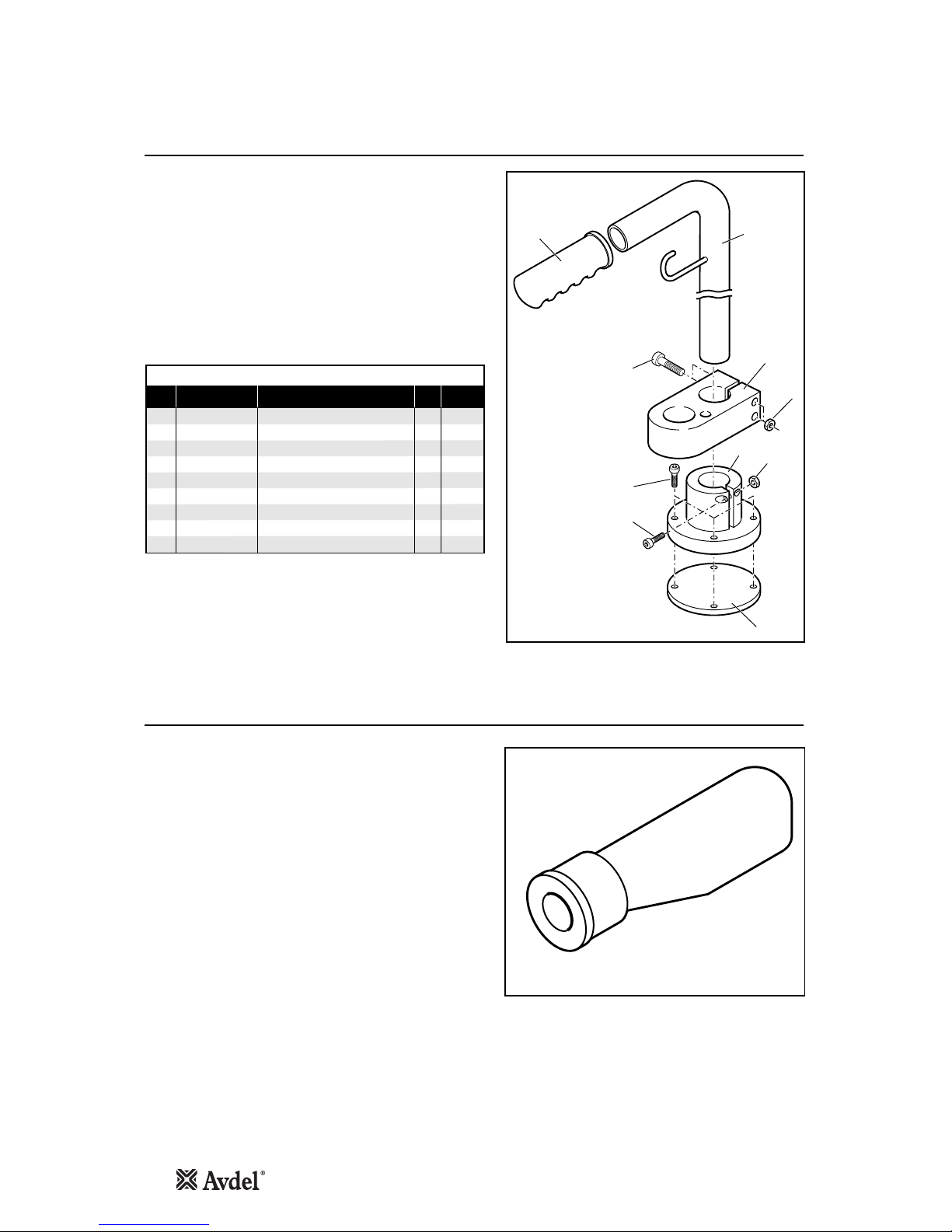
Handling and Holster Kit
Accessories
07265-09500 PARTS LIST
ITEM PART Nº DESCRIPTION QTY SPARES
1 07265-09501 RUBBER HANDLE 1 2 07265-09502 TUBE WITH HOOK 1 3 07265-09504 M5 BOLTS 2 4 07265-09503 HOLSTER 1 5 07265-09505 M5 NUTS 3 6 07265-09508 BASE 1 7 07265-09507 M5 BOLT 4 8 07265-09506 M5 BOLT 1 9 07265-09509 PLATE 1 -
This kit enables an easier handling of the cabinet around the
workplace and allows the tool pistol to be stored in a convenient
position.
Pin Tail Deflector
Pin Tail Deflector Part No 07220-00215
Item numbers in bold refer to the general assembly and parts list
on pages 16 and 17.
• To replace the stem catcher with a pin tail deflector remove stem
catcher end cap 38 and silencer 39.
• Unscrew screws 36 and remove stem catcher assembly together
with end cover 40.
• Unscrew screws 15 and remove adaptor 14.
• Push pin tail deflector onto the boss on stop cover 13.
9
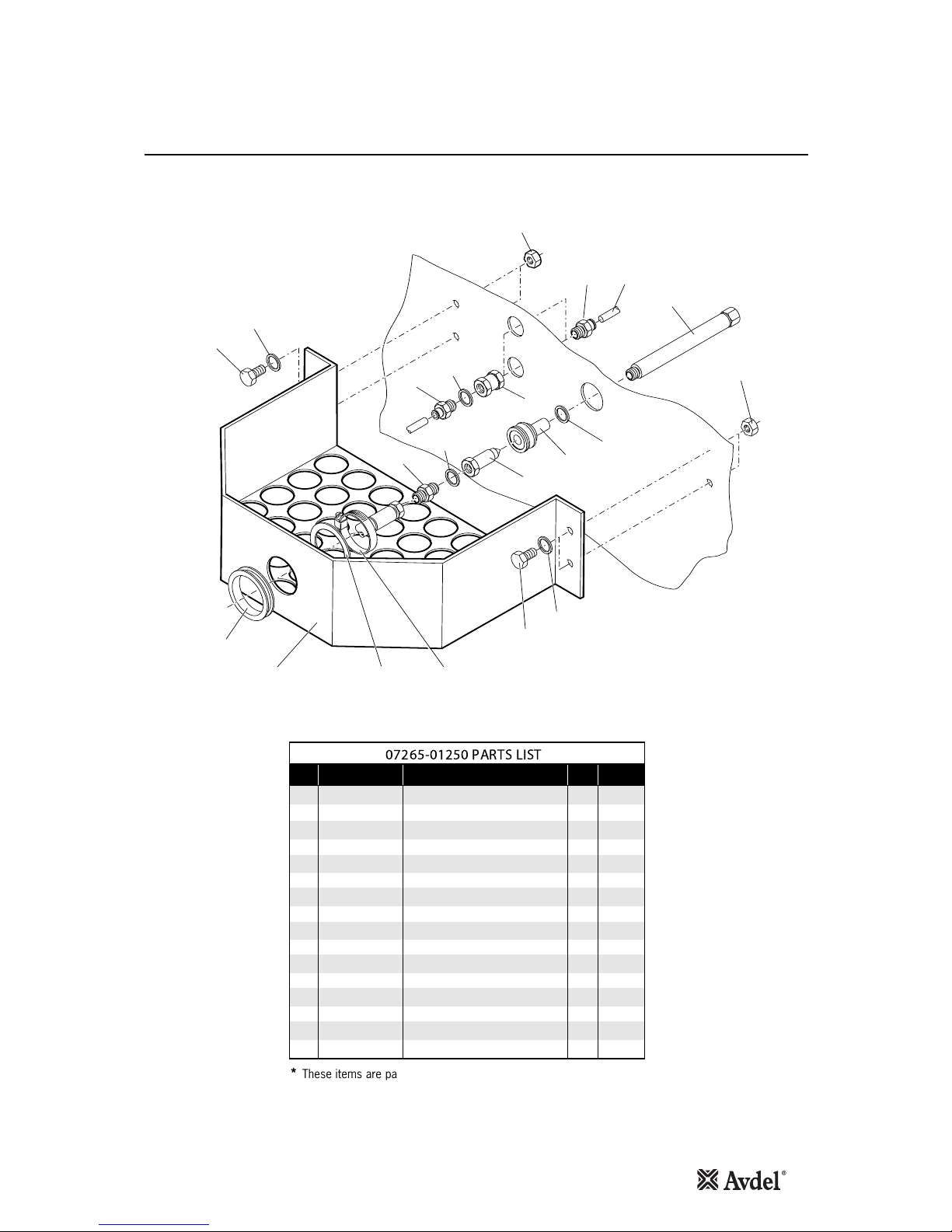
Quick Connect Kit
1
23
4
1
5
6
*14
*157 *16
8
9
10
11
9
13
12
2
6
5
Accessories
1 07265-03206 NUT 4 -
2 07265-03269 CONNECTION 4 -
3 07265-03295 AIR HOSE EXTENSION 2 -
4 07265-09296 OIL HOSE EXTENSION 1 -
5 07265-03204 WASHER 4 -
6 07265-03205 SCREW 4 -
7 07265-03297 TRAY 1 -
8 07265-03258 NIPPLE1-
9 07265-03259 WASHER 2 -
10 07265-02056 QUICK FITTING NIPPLE1-
11 07265-02055 QUICK FITTING COUPLER1 -
12 07265-03272 WASHER 2 -
13 07265-03221 CONNECTOR 2 -
*14 07265-03290 RUBBER RING 1 -
*15 07265-03291 SPACER WASHER 1 -
*16 07265-03292 CLAMP 1 -
ITEM PART N… DESCRIPTION QTY SPARES
07265-01250 PARTS LIST
* These items are part of the Base Tool and are not part of the Quick
Connect Kit
This kit enables rapid connection of the handle and hose to the cabinet.
 Loading...