

Page 1

VPNmanager® Configuration Guide
Release 3.7
670-100-600
Issue 4
May 2005
Page 2

Copyright 2005, Avaya Inc.
All Rights Reserved
Notice
Every effort was made to ensure that the information in this document
was complete and accurate at the time of release. However, information
is subject to change.
Warranty
Avaya Inc. provides a limited warranty on this product. Refer to your
sales agreement to establish the terms of the limited warranty. In
addition, Avaya’s standard warranty language as well as information
regarding support for this product, while under warranty, is available
through the following website:
http://www.avaya.com/support
Preventing Toll Fraud
“Toll fraud” is the unauthorized use of your telecommunications system
by an unaut horized pa rty (for exam ple, a person who is not a corporate
employee, agent, subcontractor, or is not working on your company's
behalf). Be aware that there may be a risk of toll fraud associated with
your system and that, if toll fraud occurs, it can result in substantial
additional charges for your telecommunications services.
Avaya Fraud Intervention
If you suspect that you are being victimized by toll fraud and you need
technical assistance or support, in the United States and Canada, call the
Technical Service Center's Toll Fraud Intervention Hotline at
1-800-643-2353.
Disclaimer
Avaya is not responsible for any modifications, additions or deletions to
the original published version of this documentation unless such
modifications, additions or deletions were performed by Avaya. Customer
and/or End User agree to indemnify and hold harmless Avaya. Avaya’s
agents, servants and employees against all claims, lawsuits, demands
and judgements arising out of, or in connection with, subsequent
modifications, additions or deletions to this documentation to the extent
made by the Customer or End User.
How to Get Help
For additional support telephone numbers, go to the Avaya Web site:
http://www.avaya.com/support/. If you are:
• Within the United States, click Escalation Manageme nt link.
Then click the appropriate link for the type of support you
need.
• Outside the United States, click Escalation Management link.
Then click International Services link that includes telephone
numbers for the International C ent ers of Excel lenc e.
Providing Telecommunications Security
Telecommunications security (of voice, data, and/or video
communications) is the prevention of any type of intrusion to (that is,
either unauthorized or malicio us access to or use of) your company's
telecommunications equ ipm ent by some part y.
Your company's “telecommunications equipment” includes both this
Avaya product and any other voice/data/video equipment that could be
accessed via this Avaya product (that is, “networked equipment”).
An “outside party” is anyone who is not a corporate employee, agent,
subcontractor, or is not working on your company's behalf. Whereas, a
“malicious party” is anyone (including someone who may be otherwise
authorized) who accesses your telecommunications equipment with
either malicious or mischievous intent.
Be aware that there may be a risk of unauthorized intrusions associated
with your system and/or its networked equipment. Also realize that, if
such an intrusion should occur, it could result in a variety of losses to
your company (including but not limited to, human/data privacy,
intellectual property, material assets, financial resources, labor costs,
and/or legal costs).
Responsibility for Your Company’s Telecommunications Security
The final responsibility for securing both this system and its networked
equipment rests with you - Avaya’s customer system administrator, your
telecommunications peers, and your managers. Base the fulfillment of
your responsibility on acquired knowledge and resources from a variety
of sources including but not limited to:
• Installation documents
• System administration documents
• Security documents
• Hardware-/software-based security tools
• Shared information between you and your peers
• Telecommunications secu ri ty expe rts
To prevent intrusions to your telecommunications equipment, you and
your peers should carefully program and configure:
• Your Avaya-provided telecommunications systems and their
interfaces
• Your Avaya-provided software applications, as well as their
underlying hardware/software platforms and interfaces
• Any other equipment networked to your Avaya products.
TCP/IP Facilities
Customers may ex perien ce dif fer ences i n prod uct p erforma nce, relia bili ty
and security depending upon network configurations/design and
topologies, even when the product performs as warranted.
Standards Compliance
Avaya Inc. is not responsible for any radio or television interference
caused by unauthorized modifications of this equipment or the
substitution or attachment of connec ting cab le s and equ ipme nt oth er
than those specified by Avaya Inc. The correction of interference caused
by such unauthorized modifications, substitution or attachment will be the
responsibility of the user. Pursuant to Part 15 of the Federal
Communications Commission (FCC) Rules, the user is cautioned that
changes or modifications not expressly approved by Avaya Inc. could
void the user’s authority to operate this equipment.
Product Safety Standards
This product complies with and conforms to the following international
Product Safety standards as applicable:
• Safety of Information T echnology Equipment, IEC 60950, 3rd
Edition including all relevant national deviations as listed in
Compliance with IEC for Electrical Equipment (IECEE)
CB-96A.
• Safety of Information Technology Equipment, CAN/
CSA-C22.2 No. 60950-00 / UL 60950, 3rd Edition
• Safety Requirements for Customer Equipment, ACA
Technical Standard (TS) 001 - 1997
• One or more of the following Mexican national standards, as
applicable: NOM 001 SCFI 1993, NOM SCFI 016 1993, NOM
019 SCFI 1998
Electromagnetic Compatibility (EMC) Standards
This product complies with and conforms to the following international
EMC standards and all relevant national deviations:
Limits and Methods of Measurement of Radio Interference of Information
Technology Equipment, CISPR 22: 199 7 and EN5 50 22: 199 8.
Such intrusions may be either to/through synchronous (time-multiplexed
and/or circuit-based) or asynchronous (character-, message-, or
packet- based) equipment or interfaces for reasons of:
• Utilization (of capabilities special to the accessed equipment)
• Theft (such as, of intellectual property, financial assets, or
toll-facility access)
• Eavesdropping (priv acy invasions to humans)
• Mischief (troubling, but apparently innocuous, tampering)
• Harm (such as harmful tampering, data loss or alteration,
regardless of motive or intent)
Information Technology Equipment – Immunity Characteristics – Limits
and Methods of Measurement, CISPR 24:1997 and EN55024:1998,
including:
• Electrostatic Discharge (ESD) IEC 61000-4-2
• Radiated Immunity IEC 61000-4-3
• Electrical Fast Transient IEC 61000-4-4
• Lightning Effects IEC 61000-4-5
• Conducted Immunity IEC 61000-4-6
• Mains Frequency Magnetic Field IEC 61000-4-8
• Voltage Dips and Variations IEC 61000-4-11
• Powerline Harmonics IEC 61000-3-2
• Voltage Fluctuations and Flicker IEC 61000-3-3
Page 3

Federal Communications Commission Statement
Part 15:
Note: This equipment has been tested and found to comply with the
limits for a Class A digital device, pursuant to Part 15 of the FCC
Rules. These limits are designed to provide reasonable protection
against harmful interference when the equipment is operated in a
commercial environment. This equipment gener ates, uses, and can
radiate radio frequency energy and, if not installed and used in
accordance with the instruction manual, may cause harmful
interference to radio communications. Operation of this equipment in
a residential area is likely to cause harmful interference in which
case the user will be required to correct the interference at his own
expense.
Canadian Department of Communications (DOC) In terference
Information
This Class A digital apparatus complies with Canadian ICES-003.
Cet appareil numérique de la classe A est conforme à la norme NMB-003
du Canada.
This equipment meets the applicable Industry Canada Terminal
Equipment Technical Specifications. This is confirmed by the registration
number. The abbreviation, IC, before the registration number signifies
that registration was performed based on a Declaration of Conformity
indicating that Industry Canada technical specifications were met. It does
not imply that Industry Canada approved the equipment.
DECLARATIONS OF CONFORMITY
United States FCC Part 68 Supplier’s Declaration of Conformity
(SDoC)
Avaya Inc. in the United States of America hereby certifies that the
equipment described in this document and bearing a TIA TSB-168 label
identification number complies with the FCC’s Rules and Regulations 47
CFR Part 68, and the Administrative Council on Terminal Attachments
(ACTA) adopted technical criteria.
Avaya further asserts that Avaya handset-equipped terminal equipment
described in this document complies with Paragraph 68.316 of the FCC
Rules and Regulations defining Hearing Aid Compatibility and is deemed
compatible with hearing aids.
Copies of SDoCs signed by the Responsible Party in the U. S. can be
obtained by contacting your local sales representative and are available
on the following Web site:
http://www.avaya.com/support
Japan
This is a Class A product based on the standard of the Voluntary Control
Council for Interference by Information Technology Equipment (VCCI). If
this equipment is used in a domestic environment, radio disturbance may
occur, in which case, the user may be required to take corrective actions.
China
BMSI (Chinese Warning Label)
Hardware, including technical data, is subject to U.S. export control laws,
including the U.S. Export Administration Act and its associated
regulations, and may be subject to export or import regulations in other
countrie s. Customer agrees to comply strictly with all such regulations
and acknowledges that it has the responsibility to obtain licenses to
export, re-export, or import hardware.
Acknowledgments:
This product includes software developed by the Apache Software
Foundation (http://www.apache.org).
Environmental Health and Safety:
!
WARNING:
Risk of explosion if battery is replaced by an incorrect type. Dispose of
used batt e ries accor ding to Avaya Environmental Health and Safet y
guidelines.
Documentation:
For the most current versions of documentation, go to the Avaya support
Web site: http://www.avaya.com/support/
All Avaya media servers and media gateways are compliant with FCC
Part 68, but many have been registered with the FCC before the SDoC
process was available. A list of all Avaya registered products may be
found at:
http://www.part68.org/
by conducting a search using “Avaya” as manufacturer.
European Union Declarations of Conformity
Avaya Inc. declares that the equipment specified in this document
bearing the “CE” (Conformité Europeénn e) mark conforms to the
European Union Radio and Telecommunications Terminal Equipment
Directive (1999/5/EC), including the Electromagnetic Compatibility
Directive (89/336/EEC) and Low Voltage Directive (73/23/EEC). This
equipment has been certified to meet CTR3 Basic Rate Interface (BRI)
and CTR4 Primary Rate Interface (PRI) and subsets thereof in CTR12
and CTR13, as applicable.
Copies of these Declarations of Conform ity (DoCs) can be obtai ne d by
contacting your local sales representative and are available on the
following Web site:
http://www.avaya.com/support
Page 4

Page 5

Contents
Preface . . . . . . . . . . . . . . . . . . . . . . . . . . . . . . . . . . . . . . . . 15
What Products are Covered . . . . . . . . . . . . . . . . . . . . . . . . . . . . . . . . . . . . 15
VPNmanager Overview . . . . . . . . . . . . . . . . . . . . . . . . . . . . . . . . . . . . . . 15
Network-wide Visibility and Control . . . . . . . . . . . . . . . . . . . . . . . . . . . . . . 16
Intranet and Extranet Support. . . . . . . . . . . . . . . . . . . . . . . . . . . . . . . . . 16
Secure VPN Configuration . . . . . . . . . . . . . . . . . . . . . . . . . . . . . . . . . . 16
No Special Consoles Required . . . . . . . . . . . . . . . . . . . . . . . . . . . . . . . . 16
Complementary to SNMP Management Tools . . . . . . . . . . . . . . . . . . . . . . . . 17
Using VPNmanager Help . . . . . . . . . . . . . . . . . . . . . . . . . . . . . . . . . . . 17
Related Documentation . . . . . . . . . . . . . . . . . . . . . . . . . . . . . . . . . . . . . . 17
How This Book Is Organized . . . . . . . . . . . . . . . . . . . . . . . . . . . . . . . . . . . 17
Contacting Technical Support . . . . . . . . . . . . . . . . . . . . . . . . . . . . . . . . . . . 19
Chapter 1: Overview of implementation . . . . . . . . . . . . . . . . . . . . . . . . . 21
Components of the Avaya security solution . . . . . . . . . . . . . . . . . . . . . . . . . . . . 21
Security gateways. . . . . . . . . . . . . . . . . . . . . . . . . . . . . . . . . . . . . . . 21
VPNremote Client software . . . . . . . . . . . . . . . . . . . . . . . . . . . . . . . . . . 22
VPNmanager software . . . . . . . . . . . . . . . . . . . . . . . . . . . . . . . . . . . . 22
Overview of the VPN management hierarchy . . . . . . . . . . . . . . . . . . . . . . . . . . . 23
Preparing to configure your network. . . . . . . . . . . . . . . . . . . . . . . . . . . . . . . .24
Security gateway . . . . . . . . . . . . . . . . . . . . . . . . . . . . . . . . . . . . . . . 24
Static Routes . . . . . . . . . . . . . . . . . . . . . . . . . . . . . . . . . . . . . . .26
IP groups . . . . . . . . . . . . . . . . . . . . . . . . . . . . . . . . . . . . . . . . . . . 26
Remote users and user groups . . . . . . . . . . . . . . . . . . . . . . . . . . . . . . . . 26
VPN . . . . . . . . . . . . . . . . . . . . . . . . . . . . . . . . . . . . . . . . . . . . . . 26
Security policies . . . . . . . . . . . . . . . . . . . . . . . . . . . . . . . . . . . . . . . . 27
Firewall policies . . . . . . . . . . . . . . . . . . . . . . . . . . . . . . . . . . . . . .27
Denial of Service . . . . . . . . . . . . . . . . . . . . . . . . . . . . . . . . . . . . . 27
QoS . . . . . . . . . . . . . . . . . . . . . . . . . . . . . . . . . . . . . . . . . . . . 28
VoIP . . . . . . . . . . . . . . . . . . . . . . . . . . . . . . . . . . . . . . . . . . . . . . 28
Additional features . . . . . . . . . . . . . . . . . . . . . . . . . . . . . . . . . . . . . . 29
NAT . . . . . . . . . . . . . . . . . . . . . . . . . . . . . . . . . . . . . . . . . . . . 29
SNMP . . . . . . . . . . . . . . . . . . . . . . . . . . . . . . . . . . . . . . . . . . . 29
Syslog. . . . . . . . . . . . . . . . . . . . . . . . . . . . . . . . . . . . . . . . . . . 30
Client IP address pooling . . . . . . . . . . . . . . . . . . . . . . . . . . . . . . . . . 30
SSL for Directory Server . . . . . . . . . . . . . . . . . . . . . . . . . . . . . . . . . 30
Sequence to configure your VPN . . . . . . . . . . . . . . . . . . . . . . . . . . . . . . . . .30
Issue 4 May 2005 5
Page 6

Contents
Chapter 2: Using VPNmanager . . . . . . . . . . . . . . . . . . . . . . . . . . . . . . 33
About VPNmanager administrators . . . . . . . . . . . . . . . . . . . . . . . . . . . . . . . . 33
Role Based Management . . . . . . . . . . . . . . . . . . . . . . . . . . . . . . . . . . . 33
Log into the VPNmanager console . . . . . . . . . . . . . . . . . . . . . . . . . . . . . . . . 35
Add a policy server . . . . . . . . . . . . . . . . . . . . . . . . . . . . . . . . . . . . 35
Open Domain . . . . . . . . . . . . . . . . . . . . . . . . . . . . . . . . . . . . . . . . . 36
Navigating the main window. . . . . . . . . . . . . . . . . . . . . . . . . . . . . . . . . . . . 36
File menu . . . . . . . . . . . . . . . . . . . . . . . . . . . . . . . . . . . . . . . . . 37
Edit menu . . . . . . . . . . . . . . . . . . . . . . . . . . . . . . . . . . . . . . . . . 39
View menu . . . . . . . . . . . . . . . . . . . . . . . . . . . . . . . . . . . . . . . .39
Tools menu . . . . . . . . . . . . . . . . . . . . . . . . . . . . . . . . . . . . . . . .40
Help menu . . . . . . . . . . . . . . . . . . . . . . . . . . . . . . . . . . . . . . . .40
Toolbar . . . . . . . . . . . . . . . . . . . . . . . . . . . . . . . . . . . . . . . . . . . . 40
VPN view pane . . . . . . . . . . . . . . . . . . . . . . . . . . . . . . . . . . . . . . . . 42
Network Diagram View . . . . . . . . . . . . . . . . . . . . . . . . . . . . . . . . . . 42
Tiled View. . . . . . . . . . . . . . . . . . . . . . . . . . . . . . . . . . . . . . . . . 43
Tree View . . . . . . . . . . . . . . . . . . . . . . . . . . . . . . . . . . . . . . . . . 43
Alarm monitoring pane . . . . . . . . . . . . . . . . . . . . . . . . . . . . . . . . . . . .44
Configuration Console window . . . . . . . . . . . . . . . . . . . . . . . . . . . . . . . . . . 44
Configuration Console Menu bar . . . . . . . . . . . . . . . . . . . . . . . . . . . . . . . 45
File menu . . . . . . . . . . . . . . . . . . . . . . . . . . . . . . . . . . . . . . . . . 45
Edit menu . . . . . . . . . . . . . . . . . . . . . . . . . . . . . . . . . . . . . . . . . 45
View menu . . . . . . . . . . . . . . . . . . . . . . . . . . . . . . . . . . . . . . . .46
Tools menu . . . . . . . . . . . . . . . . . . . . . . . . . . . . . . . . . . . . . . . .46
Toolbar . . . . . . . . . . . . . . . . . . . . . . . . . . . . . . . . . . . . . . . . . . 47
Contents pane . . . . . . . . . . . . . . . . . . . . . . . . . . . . . . . . . . . . . . 47
Details pane. . . . . . . . . . . . . . . . . . . . . . . . . . . . . . . . . . . . . . . . 47
Update Devices . . . . . . . . . . . . . . . . . . . . . . . . . . . . . . . . . . . . . . . . . . 47
Preferences . . . . . . . . . . . . . . . . . . . . . . . . . . . . . . . . . . . . . . . . . . . . 48
General tab . . . . . . . . . . . . . . . . . . . . . . . . . . . . . . . . . . . . . . . . . . 48
Dyna Policy Defaults (User). . . . . . . . . . . . . . . . . . . . . . . . . . . . . . . . . . 49
Dyna Policy Defaults (Global). . . . . . . . . . . . . . . . . . . . . . . . . . . . . . . . . 49
Dyna Policy Authentication . . . . . . . . . . . . . . . . . . . . . . . . . . . . . . . . . . 50
Advanced . . . . . . . . . . . . . . . . . . . . . . . . . . . . . . . . . . . . . . . . . . . 51
Remote Client . . . . . . . . . . . . . . . . . . . . . . . . . . . . . . . . . . . . . . . . . 51
Alarm/Monitoring . . . . . . . . . . . . . . . . . . . . . . . . . . . . . . . . . . . . . . . 52
TEP Policy. . . . . . . . . . . . . . . . . . . . . . . . . . . . . . . . . . . . . . . . . . . 52
6 Avaya VPNmanager Configuration Guide Release 3.7
Page 7

Chapter 3: Setting up the network . . . . . . . . . . . . . . . . . . . . . . . . . . . . 55
New VPN Domain . . . . . . . . . . . . . . . . . . . . . . . . . . . . . . . . . . . . . . . . . 55
Configuring a security gateway . . . . . . . . . . . . . . . . . . . . . . . . . . . . . . . . . . 57
Creating a new security gateway . . . . . . . . . . . . . . . . . . . . . . . . . . . . . . . 57
Using Device tabs to configure the security gateway . . . . . . . . . . . . . . . . . . . . . . . 59
General tab . . . . . . . . . . . . . . . . . . . . . . . . . . . . . . . . . . . . . . . . . . 60
Memo tab . . . . . . . . . . . . . . . . . . . . . . . . . . . . . . . . . . . . . . . . . . . 62
DNS tab . . . . . . . . . . . . . . . . . . . . . . . . . . . . . . . . . . . . . . . . . . . . 63
Configuring the DNS tab for security gateways at 4.3 or later . . . . . . . . . . . . . . 63
Configuring the DNS tab for VSU at VPNos 4.2 or earlier . . . . . . . . . . . . . . . . 65
Interfaces tab . . . . . . . . . . . . . . . . . . . . . . . . . . . . . . . . . . . . . . . . . 66
Options for IP addressing for interface zones . . . . . . . . . . . . . . . . . . . . . . 70
Static addressing . . . . . . . . . . . . . . . . . . . . . . . . . . . . . . . . . . . . . 70
DHCP addressing. . . . . . . . . . . . . . . . . . . . . . . . . . . . . . . . . . . . . 70
Point-to-Point Protocol Over Ethernet (PPPoE) Client . . . . . . . . . . . . . . . . . . 71
Local DHCP Server . . . . . . . . . . . . . . . . . . . . . . . . . . . . . . . . . . . . 71
DHCP Relay . . . . . . . . . . . . . . . . . . . . . . . . . . . . . . . . . . . . . . . 73
Static . . . . . . . . . . . . . . . . . . . . . . . . . . . . . . . . . . . . . . . . . . . 73
Changing network interfaces . . . . . . . . . . . . . . . . . . . . . . . . . . . . . . . 73
Private port tab . . . . . . . . . . . . . . . . . . . . . . . . . . . . . . . . . . . . . . . . 76
Adding an IP Device Configuration . . . . . . . . . . . . . . . . . . . . . . . . . . . . 77
DHCP Relay . . . . . . . . . . . . . . . . . . . . . . . . . . . . . . . . . . . . . . . 78
None . . . . . . . . . . . . . . . . . . . . . . . . . . . . . . . . . . . . . . . . . . . 79
Device users tab . . . . . . . . . . . . . . . . . . . . . . . . . . . . . . . . . . . . . . . 79
Network Object tab . . . . . . . . . . . . . . . . . . . . . . . . . . . . . . . . . . . . . . 80
Routing . . . . . . . . . . . . . . . . . . . . . . . . . . . . . . . . . . . . . . . . . . . . 81
Default Gateway for VPN Traffic (VPNos 3.X) . . . . . . . . . . . . . . . . . . . . . . . . 83
Policies tab, NAT services. . . . . . . . . . . . . . . . . . . . . . . . . . . . . . . . . . .85
About NAT types for VPNos 4.31 . . . . . . . . . . . . . . . . . . . . . . . . . . . . . 85
Configuring NAT (VPNos 4.31) . . . . . . . . . . . . . . . . . . . . . . . . . . . . . . 86
About NAT types for VPNos 3.X . . . . . . . . . . . . . . . . . . . . . . . . . . . . . . . 88
NAT applications . . . . . . . . . . . . . . . . . . . . . . . . . . . . . . . . . . . . . 88
Accessing the Internet from private networks. . . . . . . . . . . . . . . . . . . . . . . 89
Setting up VPN with overlapping private addresses . . . . . . . . . . . . . . . . . . . 90
Using NAT to support multiple gateway configurations . . . . . . . . . . . . . . . . . . 92
Interface for VPNos 4.2 . . . . . . . . . . . . . . . . . . . . . . . . . . . . . . . . . . . . 93
Add NAT Rule (VPNos 4.2 or earlier). . . . . . . . . . . . . . . . . . . . . . . . . . . 94
Original . . . . . . . . . . . . . . . . . . . . . . . . . . . . . . . . . . . . . . . . . . 94
Tunnel NAT rules . . . . . . . . . . . . . . . . . . . . . . . . . . . . . . . . . . . . . 95
Contents
Issue 4 May 2005 7
Page 8

Contents
Chapter 4: Configuring IP Groups . . . . . . . . . . . . . . . . . . . . . . . . . . . . 97
About IP Groups. . . . . . . . . . . . . . . . . . . . . . . . . . . . . . . . . . . . . . . . . . 97
Creating a New IP Group . . . . . . . . . . . . . . . . . . . . . . . . . . . . . . . . . 97
New IP Group . . . . . . . . . . . . . . . . . . . . . . . . . . . . . . . . . . . . . . . . . . . 98
IP Group - General tab . . . . . . . . . . . . . . . . . . . . . . . . . . . . . . . . . . . . . . 98
Add IP Group member. . . . . . . . . . . . . . . . . . . . . . . . . . . . . . . . . . . . . . . 100
Configuring an IP Group . . . . . . . . . . . . . . . . . . . . . . . . . . . . . . . . . . .101
Configuring an IP Group that connects to an extranet . . . . . . . . . . . . . . . . . . . . 102
Delete . . . . . . . . . . . . . . . . . . . . . . . . . . . . . . . . . . . . . . . . . . . . . 103
Memo . . . . . . . . . . . . . . . . . . . . . . . . . . . . . . . . . . . . . . . . . . . . . . . 104
Chapter 5: Configuring remote access users . . . . . . . . . . . . . . . . . . . . . . 105
Default client configuration . . . . . . . . . . . . . . . . . . . . . . . . . . . . . . . . . . . . 105
Using dyna-policy . . . . . . . . . . . . . . . . . . . . . . . . . . . . . . . . . . . . . . . . . 106
Configuring a global dyna-policy . . . . . . . . . . . . . . . . . . . . . . . . . . . . . . . . . 107
Dyna-Policy Defaults (User) tab. . . . . . . . . . . . . . . . . . . . . . . . . . . . . . . . 107
VPN configuration files on remote user’s computer . . . . . . . . . . . . . . . . . . . 108
Disable split tunneling. . . . . . . . . . . . . . . . . . . . . . . . . . . . . . . . . . . 108
Dyna-Policy Defaults (Global) tab. . . . . . . . . . . . . . . . . . . . . . . . . . . . . . . 108
Dyna-Policy Authentication tab . . . . . . . . . . . . . . . . . . . . . . . . . . . . . . . . 109
Local authentication. . . . . . . . . . . . . . . . . . . . . . . . . . . . . . . . . . . . 110
RADIUS authentication . . . . . . . . . . . . . . . . . . . . . . . . . . . . . . . . . . 110
LDAP authentication . . . . . . . . . . . . . . . . . . . . . . . . . . . . . . . . . . . 110
Dynamic VPNs (VPNos 3.x) . . . . . . . . . . . . . . . . . . . . . . . . . . . . . . . 110
Remote Client tab . . . . . . . . . . . . . . . . . . . . . . . . . . . . . . . . . . . . . . . 111
Client DNS resolution redirection . . . . . . . . . . . . . . . . . . . . . . . . . . . . . 111
Client DNS resolution redirection . . . . . . . . . . . . . . . . . . . . . . . . . . . . . 112
Remote Client inactivity connection time-out (VPNos 3.x) . . . . . . . . . . . . . . . . 112
Send Syslog messages. . . . . . . . . . . . . . . . . . . . . . . . . . . . . . . . . . . 112
Configure a default CCD with global dyna-policy . . . . . . . . . . . . . . . . . . . . . . . . . 113
Creating new user object . . . . . . . . . . . . . . . . . . . . . . . . . . . . . . . . . . . . . 114
Default user . . . . . . . . . . . . . . . . . . . . . . . . . . . . . . . . . . . . . . . . 115
About creating individual dynamic-policy . . . . . . . . . . . . . . . . . . . . . . . . . . . . . 115
User - General tab. . . . . . . . . . . . . . . . . . . . . . . . . . . . . . . . . . . . . . . 115
Memo tab . . . . . . . . . . . . . . . . . . . . . . . . . . . . . . . . . . . . . . . . . . . 116
Dyna-Policy tab . . . . . . . . . . . . . . . . . . . . . . . . . . . . . . . . . . . . . . . . 116
Actions tab . . . . . . . . . . . . . . . . . . . . . . . . . . . . . . . . . . . . . . . . . . 117
Configuring a remote user object . . . . . . . . . . . . . . . . . . . . . . . . . . . . . . . . . 118
8 Avaya VPNmanager Configuration Guide Release 3.7
Page 9

Information for VPNremote Client users. . . . . . . . . . . . . . . . . . . . . . . . . . . . . . 119
Using local authentication. . . . . . . . . . . . . . . . . . . . . . . . . . . . . . . . . 120
Using RADIUS authentication (VPNos 3.X and VPNos 4.31) . . . . . . . . . . . . . . 120
Using LDAP authentication (VPnos 3.X only). . . . . . . . . . . . . . . . . . . . . . . 120
Using Policy Manager for user configuration . . . . . . . . . . . . . . . . . . . . . . . . . . . 120
Client IP address pool configuration . . . . . . . . . . . . . . . . . . . . . . . . . . . . . 120
Add Client IP address pool . . . . . . . . . . . . . . . . . . . . . . . . . . . . . . . . 121
Add Client DNS . . . . . . . . . . . . . . . . . . . . . . . . . . . . . . . . . . . . . . 121
Add Client WINS . . . . . . . . . . . . . . . . . . . . . . . . . . . . . . . . . . . . . 122
To configure the Client IP configuration. . . . . . . . . . . . . . . . . . . . . . . . . . 122
Configuring client attributes . . . . . . . . . . . . . . . . . . . . . . . . . . . . . . . . . . 122
Creating a message . . . . . . . . . . . . . . . . . . . . . . . . . . . . . . . . . . . 122
Enforce brand name . . . . . . . . . . . . . . . . . . . . . . . . . . . . . . . . . . . 123
RADIUS/ACE Services . . . . . . . . . . . . . . . . . . . . . . . . . . . . . . . . . . . . . . 124
Enable RADIUS/ACE . . . . . . . . . . . . . . . . . . . . . . . . . . . . . . . . . . . 124
Settings . . . . . . . . . . . . . . . . . . . . . . . . . . . . . . . . . . . . . . . . . . . . 125
RADIUS concepts . . . . . . . . . . . . . . . . . . . . . . . . . . . . . . . . . . . . . . . 125
The RADIUS protocol . . . . . . . . . . . . . . . . . . . . . . . . . . . . . . . . . . . . .126
Add (RADIUS/ACE server) . . . . . . . . . . . . . . . . . . . . . . . . . . . . . . . . . . 126
Authenticating (secret) password . . . . . . . . . . . . . . . . . . . . . . . . . . . . . 126
RADIUS server data . . . . . . . . . . . . . . . . . . . . . . . . . . . . . . . . . . . 126
To add a RADIUS server: . . . . . . . . . . . . . . . . . . . . . . . . . . . . . . . . . 127
Contents
Chapter 6: Configuring user groups . . . . . . . . . . . . . . . . . . . . . . . . . . . 129
New user group . . . . . . . . . . . . . . . . . . . . . . . . . . . . . . . . . . . . . . . . . . 129
User Group - General tab . . . . . . . . . . . . . . . . . . . . . . . . . . . . . . . . . . . . . 130
User Group - Memo tab . . . . . . . . . . . . . . . . . . . . . . . . . . . . . . . . . . . . . . 130
User Group - Actions tab . . . . . . . . . . . . . . . . . . . . . . . . . . . . . . . . . . . . . 131
Configuring a user group . . . . . . . . . . . . . . . . . . . . . . . . . . . . . . . . . . . . . 131
Chapter 7: Configuring VPN objects . . . . . . . . . . . . . . . . . . . . . . . . . . . 133
Types of VPN objects . . . . . . . . . . . . . . . . . . . . . . . . . . . . . . . . . . . . . . . 133
SKIP VPNs . . . . . . . . . . . . . . . . . . . . . . . . . . . . . . . . . . . . . . . . . . 133
IKE VPNs . . . . . . . . . . . . . . . . . . . . . . . . . . . . . . . . . . . . . . . . . . . 134
VPN packet processing modes . . . . . . . . . . . . . . . . . . . . . . . . . . . . . . . . 134
Default VPN policy. . . . . . . . . . . . . . . . . . . . . . . . . . . . . . . . . . . . . . . . . 135
Creating a new VPN object . . . . . . . . . . . . . . . . . . . . . . . . . . . . . . . . . . . . 136
Creating a default VPN . . . . . . . . . . . . . . . . . . . . . . . . . . . . . . . . . . . . . . 136
Creating a designated VPN . . . . . . . . . . . . . . . . . . . . . . . . . . . . . . . . . . . . 137
Issue 4 May 2005 9
Page 10

Contents
Using the VPN tabs . . . . . . . . . . . . . . . . . . . . . . . . . . . . . . . . . . . . . . . . 138
General tab . . . . . . . . . . . . . . . . . . . . . . . . . . . . . . . . . . . . . . . . . . 138
General tab with IKE . . . . . . . . . . . . . . . . . . . . . . . . . . . . . . . . . . . 138
General tab with SKIP . . . . . . . . . . . . . . . . . . . . . . . . . . . . . . . . . . 139
Memo tab . . . . . . . . . . . . . . . . . . . . . . . . . . . . . . . . . . . . . . . . . . . 139
Members-Users tab . . . . . . . . . . . . . . . . . . . . . . . . . . . . . . . . . . . . . . 140
Members-IP Groups tab. . . . . . . . . . . . . . . . . . . . . . . . . . . . . . . . . . . . 140
Security (IKE) tab . . . . . . . . . . . . . . . . . . . . . . . . . . . . . . . . . . . . . . . 141
Pre-Shared Secret . . . . . . . . . . . . . . . . . . . . . . . . . . . . . . . . . . . . 144
Security (IPSec) . . . . . . . . . . . . . . . . . . . . . . . . . . . . . . . . . . . . . . . . 144
IPSec Proposals . . . . . . . . . . . . . . . . . . . . . . . . . . . . . . . . . . . . . 145
Add IPSec proposal . . . . . . . . . . . . . . . . . . . . . . . . . . . . . . . . . . . . . . 146
Actions tab . . . . . . . . . . . . . . . . . . . . . . . . . . . . . . . . . . . . . . . . . . 148
VPN configuration . . . . . . . . . . . . . . . . . . . . . . . . . . . . . . . . . . . . . . . 148
Export . . . . . . . . . . . . . . . . . . . . . . . . . . . . . . . . . . . . . . . . . . . 148
Rekey site-to-site VPN . . . . . . . . . . . . . . . . . . . . . . . . . . . . . . . . . . . . 149
Rekey . . . . . . . . . . . . . . . . . . . . . . . . . . . . . . . . . . . . . . . . . . . 149
Advanced VPN tab . . . . . . . . . . . . . . . . . . . . . . . . . . . . . . . . . . . . . . . . 149
Configuring a SKIP VPN. . . . . . . . . . . . . . . . . . . . . . . . . . . . . . . . . . . . . . 150
Configuring an IKE VPN. . . . . . . . . . . . . . . . . . . . . . . . . . . . . . . . . . . . . . 152
Enabling CRL checking . . . . . . . . . . . . . . . . . . . . . . . . . . . . . . . . . . . . . . 156
Exporting a VPN object to an extranet . . . . . . . . . . . . . . . . . . . . . . . . . . . . . . 158
VPN Object export checklist. . . . . . . . . . . . . . . . . . . . . . . . . . . . . . . . . . 159
Export procedure . . . . . . . . . . . . . . . . . . . . . . . . . . . . . . . . . . . . . . . 160
Importing a VPN object from an extranet . . . . . . . . . . . . . . . . . . . . . . . . . . . . . 161
Rekeying a VPN object . . . . . . . . . . . . . . . . . . . . . . . . . . . . . . . . . . . . . . 162
Chapter 8: Establishing security . . . . . . . . . . . . . . . . . . . . . . . . . . . . . 163
Firewall rules set up . . . . . . . . . . . . . . . . . . . . . . . . . . . . . . . . . . . . . . . . 163
Levels of firewall policy management . . . . . . . . . . . . . . . . . . . . . . . . . . . . . 163
Firewall rules . . . . . . . . . . . . . . . . . . . . . . . . . . . . . . . . . . . . . . . . . 164
Domain level firewall rules . . . . . . . . . . . . . . . . . . . . . . . . . . . . . . . . 164
Device level firewall rules . . . . . . . . . . . . . . . . . . . . . . . . . . . . . . . . . 166
Priority of Firewall rules versus NAT rules . . . . . . . . . . . . . . . . . . . . . . . . 167
Setting up firewall rules for FTP . . . . . . . . . . . . . . . . . . . . . . . . . . . . . 167
FTP and Firewall/NAT Operation . . . . . . . . . . . . . . . . . . . . . . . . . . . . . 167
Security Gateways and FTP . . . . . . . . . . . . . . . . . . . . . . . . . . . . . . . 168
Firewall templates . . . . . . . . . . . . . . . . . . . . . . . . . . . . . . . . . . . . . . . 169
Predefined templates . . . . . . . . . . . . . . . . . . . . . . . . . . . . . . . . . . . 170
User defined templates . . . . . . . . . . . . . . . . . . . . . . . . . . . . . . . . . . 170
10 Avaya VPNmanager Configuration Guide Release 3.7
Page 11

Contents
Services . . . . . . . . . . . . . . . . . . . . . . . . . . . . . . . . . . . . . . . . . . . . . . 172
Device Group . . . . . . . . . . . . . . . . . . . . . . . . . . . . . . . . . . . . . . . . . . . 173
Denial of Service . . . . . . . . . . . . . . . . . . . . . . . . . . . . . . . . . . . . . . . . . 173
Voice Over IP . . . . . . . . . . . . . . . . . . . . . . . . . . . . . . . . . . . . . . . . . . . 175
Using the IP Trunking Call Model . . . . . . . . . . . . . . . . . . . . . . . . . . . . . . . 175
Using the LRQ Required checkbox of the IP Trunking Call Model . . . . . . . . . . . . 176
Using the Gatekeeper Routed Call Model. . . . . . . . . . . . . . . . . . . . . . . . . . . 178
Add gatekeeper settings . . . . . . . . . . . . . . . . . . . . . . . . . . . . . . . . . 179
QoS policy and QoS mapping. . . . . . . . . . . . . . . . . . . . . . . . . . . . . . . . . . .180
QoS Policy . . . . . . . . . . . . . . . . . . . . . . . . . . . . . . . . . . . . . . . . 180
QoS mapping . . . . . . . . . . . . . . . . . . . . . . . . . . . . . . . . . . . . . . . 184
Packet Filtering . . . . . . . . . . . . . . . . . . . . . . . . . . . . . . . . . . . . . . . . . . 184
What can be filtered. . . . . . . . . . . . . . . . . . . . . . . . . . . . . . . . . . . . 185
Packet Filtering and NAT . . . . . . . . . . . . . . . . . . . . . . . . . . . . . . . . . 185
Advanced . . . . . . . . . . . . . . . . . . . . . . . . . . . . . . . . . . . . . . . . . . . 186
Permit/Deny non-VPN traffic Radio Buttons . . . . . . . . . . . . . . . . . . . . . . . 186
Add Packet Filtering Policy . . . . . . . . . . . . . . . . . . . . . . . . . . . . . . . . 187
From/Where. . . . . . . . . . . . . . . . . . . . . . . . . . . . . . . . . . . . . . . .188
To Where . . . . . . . . . . . . . . . . . . . . . . . . . . . . . . . . . . . . . . . . . 189
The Filtering Policy in progress . . . . . . . . . . . . . . . . . . . . . . . . . . . . . . 189
Locating this filtering policy . . . . . . . . . . . . . . . . . . . . . . . . . . . . . . . . 189
The filtering policy in progress . . . . . . . . . . . . . . . . . . . . . . . . . . . . . . 189
Running the packet filtering policy wizard. . . . . . . . . . . . . . . . . . . . . . . . . 189
Running the Policy Manager for packet filtering . . . . . . . . . . . . . . . . . . . . . 190
Starting and stopping filtering services . . . . . . . . . . . . . . . . . . . . . . . . . . 190
Managing the ACL . . . . . . . . . . . . . . . . . . . . . . . . . . . . . . . . . . . . 190
Configuring advanced filtering options . . . . . . . . . . . . . . . . . . . . . . . . . . 191
Marking packets for differentiated services (QoS) . . . . . . . . . . . . . . . . . . . . . . 192
About Differentiated Services. . . . . . . . . . . . . . . . . . . . . . . . . . . . . . . 193
How a VSU marks packets . . . . . . . . . . . . . . . . . . . . . . . . . . . . . . . . 193
Types of marking rules . . . . . . . . . . . . . . . . . . . . . . . . . . . . . . . . . . 194
How to create a packet marking rule . . . . . . . . . . . . . . . . . . . . . . . . . . . 194
Packet filtering firewall . . . . . . . . . . . . . . . . . . . . . . . . . . . . . . . . . . . . 196
Add firewall policy. . . . . . . . . . . . . . . . . . . . . . . . . . . . . . . . . . . . .197
Chapter 9: Using advanced features . . . . . . . . . . . . . . . . . . . . . . . . . . . 199
Device Advanced . . . . . . . . . . . . . . . . . . . . . . . . . . . . . . . . . . . . . . . . . 199
ARP . . . . . . . . . . . . . . . . . . . . . . . . . . . . . . . . . . . . . . . . . . . . . . 200
Path MTU Discovery . . . . . . . . . . . . . . . . . . . . . . . . . . . . . . . . . . . . .201
NAT Traversal . . . . . . . . . . . . . . . . . . . . . . . . . . . . . . . . . . . . . . . . . 203
Issue 4 May 2005 11
Page 12

Contents
Port for dyna-policy download. . . . . . . . . . . . . . . . . . . . . . . . . . . . . . . . . 204
Port for Secure Authentication . . . . . . . . . . . . . . . . . . . . . . . . . . . . . . . . 204
Private IP Address (VPNos 3.x). . . . . . . . . . . . . . . . . . . . . . . . . . . . . . . . 204
Send Device Names . . . . . . . . . . . . . . . . . . . . . . . . . . . . . . . . . . . . .205
SuperUser Password (VPNos 3.x) . . . . . . . . . . . . . . . . . . . . . . . . . . . . . . 206
Tunnel Persistence . . . . . . . . . . . . . . . . . . . . . . . . . . . . . . . . . . . . . . 207
TEP Policy. . . . . . . . . . . . . . . . . . . . . . . . . . . . . . . . . . . . . . . . . . . . . 209
Servers . . . . . . . . . . . . . . . . . . . . . . . . . . . . . . . . . . . . . . . . . . . . . . 210
Add servers . . . . . . . . . . . . . . . . . . . . . . . . . . . . . . . . . . . . . . . .210
Managing the server list. . . . . . . . . . . . . . . . . . . . . . . . . . . . . . . . . . . . 211
Resilient Tunnel . . . . . . . . . . . . . . . . . . . . . . . . . . . . . . . . . . . . . . . . . . 212
Tunnel Switching . . . . . . . . . . . . . . . . . . . . . . . . . . . . . . . . . . . . . . . 213
Creating a resilient tunnel . . . . . . . . . . . . . . . . . . . . . . . . . . . . . . . . . . . 214
Add resilient tunnel . . . . . . . . . . . . . . . . . . . . . . . . . . . . . . . . . . . . . . 215
Prerequisites . . . . . . . . . . . . . . . . . . . . . . . . . . . . . . . . . . . . . . . 215
Managing the resilient tunnel list . . . . . . . . . . . . . . . . . . . . . . . . . . . . . . . 216
Stopping and starting resilient tunnel services . . . . . . . . . . . . . . . . . . . . . . . . 217
Primary end-point service. . . . . . . . . . . . . . . . . . . . . . . . . . . . . . . . . 217
Secondary end-point service . . . . . . . . . . . . . . . . . . . . . . . . . . . . . . . 217
Failover TEP . . . . . . . . . . . . . . . . . . . . . . . . . . . . . . . . . . . . . . . . . . . 218
Configuring failover TEP . . . . . . . . . . . . . . . . . . . . . . . . . . . . . . . . . . .219
Advanced Action. . . . . . . . . . . . . . . . . . . . . . . . . . . . . . . . . . . . . . . . . . 219
Switch Flash. . . . . . . . . . . . . . . . . . . . . . . . . . . . . . . . . . . . . . . . . . 220
Reset password . . . . . . . . . . . . . . . . . . . . . . . . . . . . . . . . . . . . . . . . 220
Disable FIPS . . . . . . . . . . . . . . . . . . . . . . . . . . . . . . . . . . . . . . . . . 220
High Availability . . . . . . . . . . . . . . . . . . . . . . . . . . . . . . . . . . . . . . . . . . 221
Virtual addresses . . . . . . . . . . . . . . . . . . . . . . . . . . . . . . . . . . . . . . . 222
Advanced parameters . . . . . . . . . . . . . . . . . . . . . . . . . . . . . . . . . . 222
Members . . . . . . . . . . . . . . . . . . . . . . . . . . . . . . . . . . . . . . . . . . . 223
Configuring high availability . . . . . . . . . . . . . . . . . . . . . . . . . . . . . . . . . .224
Creating a High Availability Group . . . . . . . . . . . . . . . . . . . . . . . . . . . . 224
Updating a high availability group using Update Device . . . . . . . . . . . . . . . . . 225
Deleting a high availability group . . . . . . . . . . . . . . . . . . . . . . . . . . . . . 225
Failover . . . . . . . . . . . . . . . . . . . . . . . . . . . . . . . . . . . . . . . . . . . . . . 226
Failover reconnect. . . . . . . . . . . . . . . . . . . . . . . . . . . . . . . . . . . . . . . 229
Converged Network Analyzer Test Plug. . . . . . . . . . . . . . . . . . . . . . . . . . . . . . 230
Keep Alive . . . . . . . . . . . . . . . . . . . . . . . . . . . . . . . . . . . . . . . . . . . . . 232
12 Avaya VPNmanager Configuration Guide Release 3.7
Page 13

Policy Manager - My Certificates . . . . . . . . . . . . . . . . . . . . . . . . . . . . . . . . . 234
About VSU certificates . . . . . . . . . . . . . . . . . . . . . . . . . . . . . . . . . . 234
Creating and Installing a Signed Certificate. . . . . . . . . . . . . . . . . . . . . . . . 235
Switching certificates used by VPNmanager Console . . . . . . . . . . . . . . . . . . 237
Issuer certificates . . . . . . . . . . . . . . . . . . . . . . . . . . . . . . . . . . . . . . . 238
About Issuer Certificates . . . . . . . . . . . . . . . . . . . . . . . . . . . . . . . . . 238
Installing an issuer certificate . . . . . . . . . . . . . . . . . . . . . . . . . . . . . . . 239
IKE Certificate Usage . . . . . . . . . . . . . . . . . . . . . . . . . . . . . . . . . . . . . 240
About Certificate Usage (Exchange) . . . . . . . . . . . . . . . . . . . . . . . . . . . 241
Assigning a Target for a Certificate . . . . . . . . . . . . . . . . . . . . . . . . . . . . 241
Chapter 10: Monitoring your network . . . . . . . . . . . . . . . . . . . . . . . . . . 245
Using SNMP to monitor the device . . . . . . . . . . . . . . . . . . . . . . . . . . . . . . . .245
Adding Admin Users for SNMPv3. . . . . . . . . . . . . . . . . . . . . . . . . . . . . . . 247
VPN active sessions . . . . . . . . . . . . . . . . . . . . . . . . . . . . . . . . . . . . . 247
Syslog Services . . . . . . . . . . . . . . . . . . . . . . . . . . . . . . . . . . . . . . . . . . 248
Add Syslog Policy. . . . . . . . . . . . . . . . . . . . . . . . . . . . . . . . . . . . . 249
Using Monitor . . . . . . . . . . . . . . . . . . . . . . . . . . . . . . . . . . . . . . . . . . . 250
Enterprise MIB . . . . . . . . . . . . . . . . . . . . . . . . . . . . . . . . . . . . . . . . 250
Monitoring wizard . . . . . . . . . . . . . . . . . . . . . . . . . . . . . . . . . . . . . . . 250
Define Custom . . . . . . . . . . . . . . . . . . . . . . . . . . . . . . . . . . . . . . 267
Monitoring wizard (Presentation) . . . . . . . . . . . . . . . . . . . . . . . . . . . . . . . 268
Presentation . . . . . . . . . . . . . . . . . . . . . . . . . . . . . . . . . . . . . . .268
Monitoring alarms . . . . . . . . . . . . . . . . . . . . . . . . . . . . . . . . . . . . . . . . . 268
Alarm Types. . . . . . . . . . . . . . . . . . . . . . . . . . . . . . . . . . . . . . . .269
Contents
Report Wizard . . . . . . . . . . . . . . . . . . . . . . . . . . . . . . . . . . . . . . . . . . . 270
Generating the report . . . . . . . . . . . . . . . . . . . . . . . . . . . . . . . . . . . . . 272
Device diagnostics. . . . . . . . . . . . . . . . . . . . . . . . . . . . . . . . . . . . . . . . . 273
Chapter 11: Device management . . . . . . . . . . . . . . . . . . . . . . . . . . . . . 275
Using the Management tab . . . . . . . . . . . . . . . . . . . . . . . . . . . . . . . . . . . . 275
Setting Up SSH and Telnet . . . . . . . . . . . . . . . . . . . . . . . . . . . . . . . . . . 275
Changing device administrator’s passwords . . . . . . . . . . . . . . . . . . . . . . . . . 276
Using the Connectivity tab. . . . . . . . . . . . . . . . . . . . . . . . . . . . . . . . . . . . . 277
Check connectivity by ping . . . . . . . . . . . . . . . . . . . . . . . . . . . . . . . . . .278
Check Connectivity by Proxy Ping . . . . . . . . . . . . . . . . . . . . . . . . . . . . . . 279
Using the Device Actions tab . . . . . . . . . . . . . . . . . . . . . . . . . . . . . . . . . . . 279
Update Configuration . . . . . . . . . . . . . . . . . . . . . . . . . . . . . . . . . . . . . 280
Reset Device Time . . . . . . . . . . . . . . . . . . . . . . . . . . . . . . . . . . . . . . 280
Reboot Device. . . . . . . . . . . . . . . . . . . . . . . . . . . . . . . . . . . . . . . . . 280
Issue 4 May 2005 13
Page 14

Contents
Re-setup Device. . . . . . . . . . . . . . . . . . . . . . . . . . . . . . . . . . . . . . . . 281
Import Device Configuration. . . . . . . . . . . . . . . . . . . . . . . . . . . . . . . . . . 281
Ethernet Speed . . . . . . . . . . . . . . . . . . . . . . . . . . . . . . . . . . . . . . . . 282
Redundancy. . . . . . . . . . . . . . . . . . . . . . . . . . . . . . . . . . . . . . . . . . 283
Network Interface Status . . . . . . . . . . . . . . . . . . . . . . . . . . . . . . . . . 283
Switching . . . . . . . . . . . . . . . . . . . . . . . . . . . . . . . . . . . . . . . . . 284
Importing and exporting VPN configurations to a device . . . . . . . . . . . . . . . . . . . . . 284
Export VPN . . . . . . . . . . . . . . . . . . . . . . . . . . . . . . . . . . . . . . . . . . 284
Exporting RADIUS . . . . . . . . . . . . . . . . . . . . . . . . . . . . . . . . . . . . . . 285
Chapter 12: Upgrading firmware and licenses . . . . . . . . . . . . . . . . . . . . . 287
Centralized firmware management . . . . . . . . . . . . . . . . . . . . . . . . . . . . . . . . 287
Device - Upgrade tab . . . . . . . . . . . . . . . . . . . . . . . . . . . . . . . . . . . . . . . 288
Upgrading a security gateway’s firmware . . . . . . . . . . . . . . . . . . . . . . . . . . . 289
License . . . . . . . . . . . . . . . . . . . . . . . . . . . . . . . . . . . . . . . . . . . . 290
Encryption Strength . . . . . . . . . . . . . . . . . . . . . . . . . . . . . . . . . . . . . . 291
Remote Access (VSU-100 Only) . . . . . . . . . . . . . . . . . . . . . . . . . . . . . . . 291
Appendix A: Using SSL with Directory Server . . . . . . . . . . . . . . . . . . . . . 293
When to Configure your VPNmanager for SSL . . . . . . . . . . . . . . . . . . . . . . . . . . 293
Installing the issuer’s certificate in the policy server and
the VPNmanager Console . . . . . . . . . . . . . . . . . . . . . . . . . . . . . . . . . . . .294
Windows NT and Windows 2000 Computers . . . . . . . . . . . . . . . . . . . . . . . . . 294
Solaris OS Computers . . . . . . . . . . . . . . . . . . . . . . . . . . . . . . . . . . . .295
Installing the Issuer’s Certificate into a security gateway . . . . . . . . . . . . . . . . . . . . . 295
Appendix B: Firewall rules template . . . . . . . . . . . . . . . . . . . . . . . . . . . 297
General . . . . . . . . . . . . . . . . . . . . . . . . . . . . . . . . . . . . . . . . . . . . . . 297
Public zone firewall templates . . . . . . . . . . . . . . . . . . . . . . . . . . . . . . . . . . . 298
Private zone firewall templates . . . . . . . . . . . . . . . . . . . . . . . . . . . . . . . . . . 303
Semi-private zone firewall templates . . . . . . . . . . . . . . . . . . . . . . . . . . . . . . .305
DMZ zone firewall templates . . . . . . . . . . . . . . . . . . . . . . . . . . . . . . . . . . . 309
Management zone security . . . . . . . . . . . . . . . . . . . . . . . . . . . . . . . . . . . . 311
Converged Network Anaylyzer template . . . . . . . . . . . . . . . . . . . . . . . . . . . . . 311
Glossary . . . . . . . . . . . . . . . . . . . . . . . . . . . . . . . . . . . . . . . . 313
Index . . . . . . . . . . . . . . . . . . . . . . . . . . . . . . . . . . . . . . . . 319
14 Avaya VPNmanager Configuration Guide Release 3.7
Page 15

Preface
This Avaya VPNmanager® Configuration Guide is written for individuals who have an
understanding of how computer networks are installed, configured, and managed. It provi des
detailed information about using the Avaya VPNmanager solution to build small, medium, or
large scale Virtual Private Networks (VPNs).
VPNmanager is a Java-based software application that brings convenience, ease of use,
extended functionality, and platform independence to the management of VPNs.
What Products are Covered
Avaya’s solut ion i s a li ne of thr ee pr oduct s that ar e used for managi ng V ir tual Privat e Networks.
Each one, listed below, has been designed to meet the needs and requirements of either a
small, medium, or large network.
● VPNmanager Service Provider
● VPNmanager Enterprise
VPNmanager Overview
The VPNmanager application lets network managers def ine, configure, and manage Virtual
Private Networks (VPNs) from any location equipped with a computer running Window NT,
Window 2000, Windows 2003 Server, or Solaris.
Network managers can configure and check the status of Avaya security gateways and VPN
Service Units (VSU), add or remove remote sites and dial-in users to a VPN, configure user
authentication servers using LDAP directo ry servers or RADIUS servers, and monitor the state
of all security gateways, as well as the perfor man ce of private data transmissions using
Java-interface technology.
Issue 4 May 2005 15
Page 16

Preface
Network-wide Visibility and Control
The logical VPNmanager representation of virtual private networks simplifies their installation
and control. From a single workstation, network managers can assign users anywhere on the
network to one or more logical Groups and integrate local and remote Groups into VPNs. The
VPNmanager software provides global-level, VPN-level, group-level, client-level and
equipment-level monitoring and control capabilities, and automates the task of managing
configurations across multiple security gateways and Avaya VPNremote® Clients. Extensive
alarm-reporting and statistics-gathering capabilities allow network managers to respond in real
time to hardware, network, and security p roblems, and t o plan the ef ficient growth and ev olution
of their networks.
Intranet and Extranet Support
The VPNmanager software makes it easy to extend intranet servi ces to remote sites and users
securely. In addition, the VPNmanager’s sophisticated import and export capabilities enable
network managers from different organizations to securely link with one another into private
wide-area “extranets.” Companies can quickly link and unlink to their suppliers, customers,
consultants, and other business associates with flexibility and speed unmatched by tr aditional
communications services.
Secure VPN Configuration
Several mechanisms are employed to insure sec uri ty when ma naging VPNs. I ndustry -st andard
Secure Socket Layer (SSL) technology is used to keep confi guration traffic between the
VPNmanager and VSUs private. In addition, X.509 certificates are used by both VSUs and the
VPNmanager console providing an authentication capability, thus allowing only authorized
administrators to configure VSUs. Once authenticated, administrators can configure, modify,
restart, or upgrade any securi ty gateway in the corporate network. Finally, sensitive
cryptographic keying informati on stored in the VPNmanager database is encrypted using a
password key to prevent compromising secure network traffic.
No Special Consoles Required
The VPNmanager software runs on host environment s that support the Java Virtual Machine
(see the VPNmanager README file for a current list of supported platforms). Expensive
management consoles and proprietary management interfaces are not needed. Regardless of
the host platform, the VPNmanager software presents the same appearance and user controls.
16 Avaya VPNmanager Configuration Guide Release 3.7
Page 17

Complementary to SNMP Management Tools
Note:
The VPNmanager software is designed specifically for securely defining, configuring,
monitoring, and upgrading VPNs. The VPNmanager software is required to configure and
modify VPNs. Secure traffic running between VSUs or between VSUs and VPNremote Clients
does not require an active VPNmanager . After c onfiguring the required VPNs, the VPNmanager
can be shutdown if desired, or used to monitor securi ty gateway activity. In addition, standard
MIBs available with the VSUs enable monitoring from standard SNMP management stations.
Using VPNmanager Help
The VPNmanager comes with a context-sensitive-Help system. Use the Help system for gett ing
information about a specific command in the VPNmanager graphical user interface (GUI).
Related Documentation
Related Documentation
Be sure to read the VPNos Configur ation Gui de. I t contains important information on the proper
procedure for setting up your VSUs, which is a prerequisite to setting up a Virtual Private
Network.
VPNremote Client software inst al lati on an d usage inf ormation is found in the VPNremote Cl ient
Administrator’s Guide. This software allows the network administrator to pre-configure the
VPNremote client software for distribution to end users via the web, or on portable storage
media such as a CD or floppy disk.
You can download these documents from www.avaya.com. Click on Product Documentation,
select VPN and Security.
How This Book Is Organized
With this release of VPNmanager, the administrator’s guide was redesigned to present
information in the order that you use VPNmanager to configure a secure network.
Note: Depending on the VPNmanager version, some features described in this guide
may not apply.
Issue 4 May 2005 17
Page 18

Preface
Chapter 1: Overview of implementation, provides an overview of how to use VPNmanger for
centralized administration of your VPN and security gateway. It includes a checklist for
implmeneting the network.
Chapter 2: Using VPNmanager
, explains how to log in to VPNmanager. It also explains how to
use the VPNmanager interface, including the VPNmanager main console and the configuration
console. The VPNmanager Preferences are described here.
Chapter 3: Setting up the network
, explains how to create a domain and creat e and configur e a
security gateway. This chapter explains how to configure the Device object, including mu ltiple
zones, NAT services, DNS, and Static Route.
Chapter 4: Configuring IP Groups
, describes how to configure IP Group Objects for Data
Terminal Equipment (DTE) such as computers, printers, and network servers as members of
your VPN.
Chapter 5: Configuring remote access users
, describes how to setup and maintain individual
remote access users in the VPN. This chapter includes Dyna-Policy configuration and
information about the Policies tab including Client IP configuration RADIUS/ACE services, and
client attributes
Chapter 6: Configuring user groups
, describes how to setup and maintain logical groups that
the individual VPN remote users reside.
Chapter 7: Configuring VPN objects
, explains VPN Objects as the method for linking VSUs,
remote terminals, and LAN terminals in a fully configured VPN.
Chapter 8: Establishing security
, describes the levels of Firewall policy management and De nial
of Service available, how to configure t he security gateway for Voice over IP and how to create
and map Quality of Service (Qos) rules.
Chapter 9: Using advanced features
, describes about using certificat es, configuring the
Directory Server, resilient tunnels, and high availability groups.
Chapter 10: Monitoring your network
, describes the monitoring and reporting features of the
VPNmanager software. This includes SNMP, Syslog Services, Reports, and Alarms. These
features allow virtual real-time monitoring of the VPN performance and specific security
gateways.
Chapter 11: Device management,
describes how to optimize the VPNmanager, check
connectivity, reset the device time, reboot, resetup a secur ity gateway and how to import a VPN.
Chapter 12: Upgrading firmware and licenses
, describes how to use the automatic upgrade
feature to upgrade the firmware for a secur it y gateway or for a group of secruity gateways, and
how to add new licenses to your security gateway.
Appendix A: Using SSL with Directory Server
, describes the benefit of using secure socke t layer
(SSL) with the Directory Server.
Appendix B: Firewall rules template
, describes the predefined firewall templates that are
included in the VPNmanager.
18 Avaya VPNmanager Configuration Guide Release 3.7
Page 19

Contacting Technical Support
Technical Support is available to support contract holders of Avaya VPN products.
Domestic support
● Toll free telephone support: (866) 462-8292 (24x7)
● Email: vpnsupport@avaya.com
● Web: http://www.support.avaya.com
International Support
● For regional support telephone numbers, go to http:www.avayanetwork.com/site/GSO/
default.htm
Contacting Technical Support
Issue 4 May 2005 19
Page 20

Preface
20 Avaya VPNmanager Configuration Guide Release 3.7
Page 21

Chapter 1: Overview of implementation
Note:
Note:
Planning how your virtual private network should be configured is critical to the successful
deployment of a secure virtual private network.This chapter provides an overview of the major
features that you will configure.
Note: This chapter does not explai n how to set up a VPN or how to dete rmine what type
of security policies are required. You should understand about networking,
establishing firewall policies, and VPNs before implementing a VPN using
VPNmanager.
Components of the Avaya security solution
The Avaya security solution cons ists of the following:
● Avaya VPNmanager™
● Avaya™ SG security gateways and VPN Service Units (VSU)
Note: Beginning with VPNmanager 3.4, this configuration guide uses “security
gateway” to refer to both the security gateway and the VSU. The VPNmanager
application uses the word “Device” to refer to both of these components.
● Avaya VPNremote™ Client
Security gateways
The security gateways are desi gned to provide fi rewall coverage and VPN gateway functionali ty
for enterprises migrating towards conver ged network environments. The security gateway
performs cryptography, authentication, and filtering tasks at the boundary of the VPN.
After the security gateway is installed and configured, the secu rity gateway is transparent to
users who are logged into the VPN.
Issue 4 May 2005 21
Page 22

Overview of implementation
VPNremote Client software
VPNremote Client software is a communicati ons application t hat runs on remot e computers that
use dialup, DSL and cable connection supplied by Internet Service Providers (ISP), to connect
to the corporate VPN. When communicating with a VPN, the software seamlessly performs
authentication and cryptography tasks. To install and use the software, an account with an ISP
must first be created.
The software is install ed on the remote user’s computer and then Client Configuration
Download (CCD) can be used to configure the remote user’s Dyna-Policy™ for authentication
to a specific VPN.
When remote users log in, they connect to the ISP and type in their user authe ntication
information, if asked. Upon authent ication, an y traf fi c that use s the VPN is safel y encrypted as it
is transported through the public networks.
VPNmanager software
VPNmanager software lets network managers define, configure, manage VPN and firewall
policies, upgrade firmware, and manage remote user access policies from a central location.
The VPNmanager software combines two components, the VPNmanager Console and the
policy server.
● The VPNmanager console is a client that is used for configuring, managing, and
monitoring one or more VPNs. The consol e is a Java app licatio n that can be r un anywhere
and is used as a front-end to the policy server and the directory server.
● The policy server distri butes configurati on and security policies. The VPNmanager console
is a client that communicates with the policy server to retrieve security policies. The policy
server then communicates with the directory server.
The VPNmanager Console and the directory server can reside on separate, dedicated servers
within the network to provide better performance for updating and configuring large numbers of
security gateways. You can use either an existing Sun One Server or Microsoft Active Directory
Server to store the policies that are created.
VPNmanager software consists of different versions to meet the needs of various networks.
● VPNmanager Small Office. Use the small office version for managing up to fi ve security
gateways and unlimited VPNremote Clients.
● VPNmanager Enterprise. Use the VPNmanager Enterprise version for managing an
unlimited number of devices and VPNremote Clients.
● VPNmanager Service Provider. Use this version to manage an unlimited number of
devices and VPNremote Clients. The Service Provider also supports multiple VPN
domains, which meets the needs of ISPs.
22 Avaya VPNmanager Configuration Guide Release 3.7
Page 23
Overview of the VPN management hierarchy
● VPNmanager Enterprise Client. Use the Enterprise Client version for managing an
unlimited number of security gateways and VPNremote Clients.
● VPNmanager Service Provider Client. Use the Service Provider Client version to
manage an unlimited number of security gateways and VPNremote Clients. The Service
Provider also supports multiple VPN domains.
Overview of the VPN management hierarchy
With the VPNmanager software, you can configure and manage VPNs and firewalls from a
central location. By focusing on secur ity policy instead of individual device management,
administration of large-scale networks is simplified. Central management allows you to make
configuration updates automatica lly to al l af f ecte d security gateways. This dist ribut ed approach
also applies to firewall management.
The VPNmanager software is built on a policy-based architecture that allows the administrator
to start at a high-lev el with a VPN domain, then move down t he hierarchy to create user gr oups,
IP groups for protected resources, and security groups that define membe rship and policies of
the VPN.
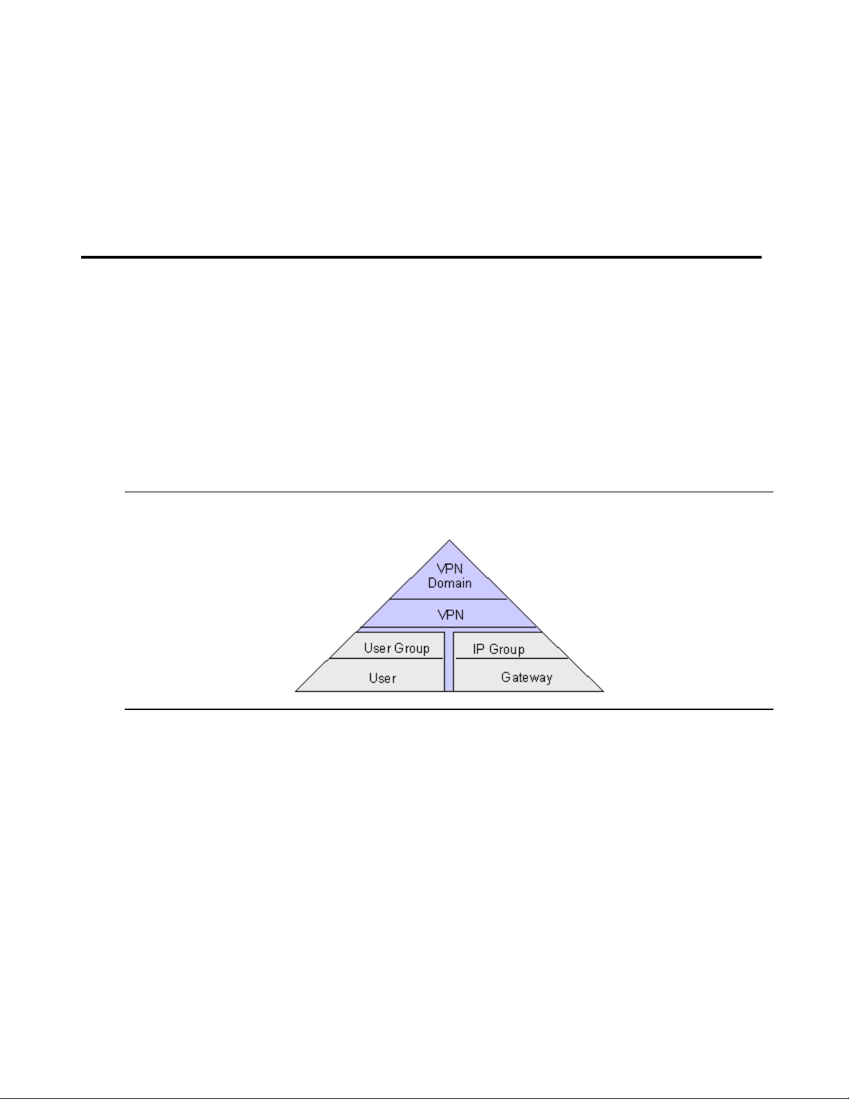
Figure 1: Domain hierarchy
At the peak of the hierarchy is the VPN domain. A domain is as sig ned a name to ident ify i t from
other domains. Usually one domain is configured fo r an entire or ganizat ion. A domain is bui lt of
one or more VPNs.
Each VPN is built of users, user groups and IP groups. VPNs are assigned names. These
names can associate the VPN to a regional location or purpose.
Users are the individual remote ac cess user s who log in to the VPN thr ough a securit y gateway.
The VPNremote Client software is used to connect to the VPN services.
A User Group contains or organizes user accounts. These accounts are assigned to remote
VPN members who dial in to the network and run VPNremote Client software to access the
VPN.
Issue 4 May 2005 23
Page 24

Overview of implementation
An IP Group contains the IP addresses that belong to a specif ic LAN. Any device connected to
the LAN can use these addresses. A VPN can have many IP Groups so addresses can be
consolidated to meet the needs of an organization.
The security gateway is configured to provide VPN gateway functionally and firewall coverage.
VPNmanager security management includes creating domain-level firewall rules and
device-level firewall rules. VPNmanager provides multiple firewall templates that can be used
as a general rule set or as a starting point for creating a customized firewall template. You can
apply these templates at the domain level for al l security gateways, for a specific security
gateway (device-level), or for a defined device group.
Preparing to configure your network
Before you use VPNmanager to build your VPN and establish your VPN security policies, you
need to know how the VPN should be implemented. This section gives a overview of what
information you should know before you begin.
The following are functions or tasks that need to be addressed:
● How the security gateway will be configured for your network
● Which remote users will be configured on a security gateway
● What IP addresses to configure and group
● What type of security policies you want to implement
● What VPN services to use
● What advanced features, such as VoIP, Failover, or SNMP will be implemented
Security gateway
The security gateway is preconfigured with default settings for the media interface zones and
Network Address Tr anslation (NAT). You may need to change default configuration for your
specific network environment.
Up to six media interfaces can be configured with different zone interfaces. The number of
zones that can be configured depends on the security gateway model (Table 1
Ethernet1 are present in all models and are assigned to the public and the private zones. The
media interfaces that remain are unused and can be configu red as required.
). Ethernet0 and
● Public zone. Public zone provides connection to the Internet, usually by way of a wide
area network (WAN).
● Private zone. Private zone is used to provide connection to your private local area
network (LAN) or to your corporate LAN.
24 Avaya VPNmanager Configuration Guide Release 3.7
Page 25

Preparing to configure your network
● Public-backup zone. Public-backup zone is the backup interface to the primary public
interface for use when Failover is configured.
● Semiprivate zone. Semiprivate zone is used for media such as wireless LAN, where the
network is considered part of the protected network, but the media may be vulnerable to
attack. The semi-private zone provides the additional security measure of IPSec
encryption to prevent compromise to the network, for example, VPN over wireless
protection.
● DMZ zone. DMZ (Demilitarized zone) is used for an area in the company network that
needs to be accessible from the public networks, for example, email, FTP, and Web
servers, but the area is not considered p art of the internal private network. Serv ers in the
DMZ typically have publicly rout able IP addres ses or shou ld use adva nced NAT within the
security gateway.
● Management zone. Management zone is used to simplify network deployments, to
eliminate enterprise network dependencies on switches or routers. The management
network interface is usually used as an access poi nt for a dedicated VPNmanager
management station or as a dedicated interfac e for dumping log messages to a syslog
server.
Table 1: Network zones
Media type SG5 and SG5X SG200 SG203 SG208
Ethernet0 Public Public Private Private
Ethernet1 Private Private Public Public
Ethernet2 NA
Ethernet3 to
NA NA
● Unused
● Public backup
● Private
● Semiprivate
● DMZ
● Management
● Unused
● Unused
● Public backup
● Private
● Semiprivate
● DMZ
● Management
● Unused
Ethernet5
● Public backup
● Private
● Semiprivate
● DMZ
● Management
● Public backup
● Private
● Semiprivate
● DMZ
● Management
Issue 4 May 2005 25
Page 26

Overview of implementation
St atic Routes
Static routes are specified when more than one router exists on a network to which the security
gateway must forward either VPN traffic or non-VPN tr affic. You can build a static route table
with up to 32 network address/mask pair s.
IP groups
Data Terminal Equipment (DTE); such as computers, print ers, and network server s, are devices
that can be members of a VPN. To make these devices members, you create IP Group s. An IP
Group is composed of a set of hosts (workstati ons and servers) that are located behind a
common security gateway. The hosts are defined by their IP address and mask. VPNs are
made up of IP groups at multiple locations linked across a public IP network (Internet).
Assigning workstations and servers to different IP groups offers a powerful way to limit VPN
traffic to specifically designated users.
Remote users and user groups
VPNremote Client users who log in to the VPN through the security gateway must have their
user authentication configured on that security gateway.
If RADIUS is not used, you must configure the user name and the password for each remote
user . With RADIUS, you can configure a remote user as a default user. When a remote user is
configured as a default user, the user password is not required to log in. The user is
authenticated by a third-party authentication server, such as RADIUS.
You can also change the default Internet Key Exchange (IKE) identity, the split tunneling option
and the security option.
You can configure User Groups to setup and maintain logical groups of users.
VPN
A VPN object is the method used to link security gateways, remote terminals, and LAN
terminals in a fully configured virtual private network. Creating a VPN involves naming each
VPN, adding users and user groups, and adjusting the IKE and IPSec security protocols for
VPN traffic.
26 Avaya VPNmanager Configuration Guide Release 3.7
Page 27

Security policies
Note:
VPNmanager security policy management provides the following security features that can be
configured:
● Firewall rules
● Denial of Service (DoS) categories
● Quality of Service (QoS) rules
● Bandwidth management
In addition, encryption security options include Internet Key Exchange (IKE) with IPSecuirty
protocol (IPSec). It applies globally to the VPN.
Firewall policies
VPNmanager firewall policy management includes domain firewall rules, device firewall rules,
and firewall templates . The VPNmanager software provi des multiple firewall templates that can
be used as a general rule set or as a starting point for creating a customized firewall template.
You can apply these templates at the domain level for all security gateways, for a specific
gateway, or for a defined group. The integrated SMLI (Stateful Multi-Layer Inspection) Firewall
supports firewall rules criteria based on the following:
Preparing to configure your network
● Source/Destination IP address or range
● TCP/UDP/ICMP protocol
● Port or port ranges
● IP protocol
● Interface
● Direction
A set of common network services is provided, and custom network services or objects can be
easily defined for use in both firewall and QoS policies. Firewall rules can be individually
enabled to track state i nformation on TCP/UDP/ICMP packet flows and can be us er-configured
with advanced state timers. Logi n can also be enabl ed for each rule.
Note: Domain level rules and firewall templates are available for VPNos release 4.2
and later.
Denial of Service
The following Denial of Service (DOS) categories are enabled to protect the security gateway
from attack by hackers.
Issue 4 May 2005 27
Page 28

Overview of implementation
Ping of Death. - The ping of death sends packets with invalid lengths. When the receiving
system attempts to rebuil d the packets, the system crashes because the packet length exhausts
the available memory.
IP Spoofing. - This attack sends an IP p acket with an invalid IP addres s. If the system accepts
this IP address, the attacker appears to reside on the private side of the security gateway. The
attacker is actually on the public side, and bypasses the firewall rules of the private side.
Smurf Attack. - This attack floods the system with broadcast IP packet pings. If the flood is
large enough and long enough, the attacked host is unable to receive or distinguish real traffic.
Tear Drop. - This attack sends IP fragments to the system that the receiving system cannot
reassemble and the system can crash.
Flood Attack. - This attack floods the system with TCP connecti on requests, which exhausts
the memory and the processing resources of the firewall. Flood attacks also attack the UDP
ports. This attack attempts to flood the network by exhausting the available network bandwidth.
WinNuke Attack. - This attack attempts to completel y disable networking on computers that
are running Windows 95 or Windows NT. This attack can be swift and crippling because it uses
common Microsoft NetBIOS services.
QoS
VoIP
Buffer Overflow. - This attack overflows the internal buf fers o f the a ppli cati on by sendi ng mor e
traffic than the buffers can process.
Quality of Service (QoS) allows you to classify and prioritize traffic based on DHCP values and
TCP/IP services and networks. The bandwidt h available to a class of traffic can be allotted to a
specific percentage of the total upstream bandwidth. Confi guring QoS allows VoIP traffic to
receive a higher priority. If QoS is disabled, all traffic receives the same priority.
The security gateway can be configured to protect and enable the communication of VoIP
telephones either within a VPN or firewall. The security gateway can be configured to secure
Avaya Multivantage™ and IP Office™ VoIP solutions as follows:
● Secure site-to-site voice trunks such as between headquarters and branch offices or
between main offices and home offices using VPNs.
● Secure VoIP servers or endpoints (IP telephones) by providing perimeter security using
the V oIP aware firewall fi ltering that is able t o dynamically open and clos e all port s required
to pass VoIP communication between servers and endpoints
28 Avaya VPNmanager Configuration Guide Release 3.7
Page 29

● Allow voice-secure communication wit h Avaya’s IP Softphone and IP Office Phone
Manager Pro using VPNremote Client
● Enable NAT traversal of H.323 VoIP traffic
● Optimize bandwidth for VoIP traffic using the security gateway’s Quality of Service (QoS)
policies
In order to successfully use VoIP it is important to thoroughly plan the implementation of the
feature. Avaya suggests that you read the Avaya IP Telephony Implementation Guide before
implementing VoIP.
Additional features
The following is a list of some of features that can be configured depending on your VPN
networking requirements.
NAT
Preparing to configure your network
Network Address Tr anslation (NAT) is an Internet standard that allows private (nonrout able)
networks to connect to public (routable) networks. To connect private networks and public
networks, address mapping is performed on a security gateway that i s located between the
private network and the public network.
You can set up three types of NAT mapping on the security gateway:
By default, NAT is enabled and the Share public address to reach the Internet feature is
selected. NAT affects only clear traffic.
SNMP
The VPNmanager uses the SNMP protocol to monitor the security gateway. The security
gateway includes a SNMP agent that supports MIB-II and a proprietary MIB. This agent is
read-only and cannot be used to configure the security gateway. The agent can send traps to a
list of trap agents that you configure. SNMPv1, SNMPv2c, or VNMPv3 can be selected.
● Static NAT. With static NAT, addresses from one network are permanently mapped to
addresses on another network.
● Port NAT. With port NA T, addresses from internal, nonroutable networks are t ransl ated to
one routable address in Port NAT.
● Port Redirection. With port redirection, addresses from a specific IP address and a
specific port are redirected to another IP address and port.
Issue 4 May 2005 29
Page 30

Overview of implementation
Syslog
The security gateway has a syslog messaging facility for logging system error messages. The
message can be automatically sent to a destination running a Syslog server.
Client IP address pooling
Access control devices (ACD), such as firewal ls, guard networks from unauthorized users.
Analyzing source addresses is one method ACDs use to decide which packets can enter a
network. The addresses that ISPs dynamically assign to VPNremote Client users is naturally
blocked because it is i mpossibl e to k now ahe ad of ti me whi ch addr ess is ass igne d. You need to
configure the VPNremote Cli ent IP add ress po ols f eature with th e source IP addres ses that can
be recognized by an ACD so that user access is not blocked.
SSL for Directory Server
As an added benefit, all communications with the direc tory server can be secured by SSL
(Secure Sockets Layer).
You can configure your VPN to run SSL at any time. However it is recommended that you
configure SSL before you put the VPN into service, so that the VPN services do not have to be
stopped.
Sequence to configure your VPN
The suggested order to set up your VPN is as follows. Refer to the chapters in this
VPNmanager Administrator’s Guide for details about how to create and configure these
features.
1. Create a VPN domain
2. Create the VPN
3. Create a security gateway
4. Configure needed static routes on the gateway
5. Create IP groups
6. Associate IP groups with the security gat eway
7. Associate IP groups with the VPN
8. Create new users
9. Associate users with VPNs
10. Create a VPNremote Client address pool on the gateway
30 Avaya VPNmanager Configuration Guide Release 3.7
Page 31

Sequence to configure your VPN
11. Configure firewall rules
12. Associate firewall rules with the correct gateway and security zone
13. Configure other features such as QoS, VoIP gateway, DHCP, NAT, routing, etc.
Issue 4 May 2005 31
Page 32

Overview of implementation
32 Avaya VPNmanager Configuration Guide Release 3.7
Page 33

Chapter 2: Using VPNmanager
With Avaya VPNmanager you can define, configure, and manage VPNs and firewall policies,
upgrade firmware, and manage remote user access policies. The VPNmanager graphical
interface is modularized by functions and tasks to make configuring a VPN fast and easy.
This chapter describes how to:
● Log in
● Navigate the VPNmanager Console interface
● Configure Preferences for the VPNmanager Console
● How to communicate with the security gateway
About VPNmanager administrators
When the VPNmanager software was i nst alled , during the policy ser ver l ogin c onfigur ation, yo u
configured the centralized management VPNmanager log in ID and password.
A VPNmanager administrator can also be set up as a SNMPv3 administrator.
In previous releases of VPNmanager the super user administrator was supported. Beginning
with VPNmanager 3.5, the super user administrator function has been expanded and in now
included in the role based management feature.
Role Based Management
This features allows network administrator’s to assign one or more management role(s).
Additionally, using role based access control (RBAC) in conjunction with corporate security
guidelines, the network administrat or can more effect ively and eff iciently manage the secur ity of
the corporate network.
Beginning with VPNmanager 3.5, the ro le based management f eature will suppor t three class es
of users as follows:
1. Super User
2. One super user is configurable. The super user has unlimited access control over all VPN
domains, and is the user configured from the policy server.
3. Only the super user can create VPN domains, create administrators, define RBACs for the
administrators, and change administrator passwords.
Issue 4 May 2005 33
Page 34

Using VPNmanager
4. Admin istrator with fu ll access
5. An administrator with full access can modify the configuration for VPN domains, change
their password, and be part of multiple VPN domains.
6. VPNmanager allows full-access administrator to modify objects and devices that are saved
by VPNmanager. RBAC full-access administrators can create or delete objects, update or
upgrade devices, and modify or import configuration.
7. Full-access administrators are not able to create new VPN domains, create new
administrators, or change other administrator’s passwords.
8. Administrator with read-only access
9. An administrator with read-only access can view the configuration for VPN domains,
change their password, and be part of multiple VPN domains.
10. Read-only administrators cannot create, modify, or delete objects. Additionall y, read-only
administrators cannot update or upgrade devices, modify or import configuration, reboot or
reset devices, import or apply lic enses, or change other administrator’s passwords.
To add an administrator
The Admin object is used to change the super user password and to create administrators.
1. Select Admin from the New Objects list. The New Admin dialog opens
2. Enter the administrator’s name and the admin directory password.
3. Click Apply and then click Close.
To configure an administrator to be an SNMPv3 admin
1. From the Configuration Console>Admin Contents co l umn, select t h e ad m in to be
configured as an SNMPv3 admin. Select the SNMP tab to bring it to the front.
2. Check Enable.
3. For the Security Level, select either
● Authentication and Privacy
● Authentication and No Privacy
4. Based on the selection, the privacy settings are enable or disabled.
5. In the Authentication Protocol fiel d, select either the def ault, HMAC_SHA1or HMAC_MD5
and enter a password.
6. For the privacy settings, the only available value is DES_CBC. Enter the privacy password.
7. When finished, click Save. When you configure SNMPv3 for a device, the admin name is
listed.
34 Avaya VPNmanager Configuration Guide Release 3.7
Page 35

Log into the VPNmanager console
You log in to the VPNmanager from your computer’s Start menu, Programs>Avaya>
VPNmanager>Console. You use the super user name and password that were configured
when the VPNmanager software was installed.
Figure 2: VPNmanager login screen
Log into the VPNmanager console
The first time you log in to the VPNmanager Console, you log in as the super user and add the
policy server address or the name associated with the address. See Add a policy server
page 35.
Administrators that the super user creates can log in.
To log in:
1. In the User Name field, type the administrator name, if it is not displayed.
2. Type the password that was configured when the VPNmanager software was installed.
3. The IP address or name of the policy server is listed in the Policy Servers list. Select the
Policy Server, if it is not highlighted and click Connect to log into the server.
Add a policy server
The policy server is installed during the installation of the VPNmanager Console. The policy
server distributes configuration and security policies. The VPNmanager console is a client that
communicates with the policy server to retrieve security policies. The policy server then
communicates with the directory server.
You add the policy server address the first time you login into the VPNmanager Console.
1. From the VPNmanager Login dialog, click Add.
2. Enter the name that identifies the Policy Server, if available. This is the “user fr iendly name”
on
Issue 4 May 2005 35
Page 36

Using VPNmanager
Note:
3. Enter the IP address of the Policy Server.
4. Enter the port. The default is 443.
5. Click OK. The name or address is displayed on the login screen
You can edit or delete the policy server information.
Open Domain
When you connect to the directory server, an Open Domain screen appears. A list of all
domains is displayed, with the last-selected domain highlighted.
Note: The Open Domain screen does not appear if you add a context and then click
Connect on the first logon dialog.
At this point, the main console display screen appears and the selected VPN appears in the
View VPN window.
Navigating the main window
The VPNmanager Console consists of the console main window, the Configuration Console
window and dialogs to configure and monitor domains, VPNs, and the security gateway and
network configurations related to them.
When you log in to VPNmanager for the fi rs t time, the main wi ndow is bl ank.The t itl e bar shows
No Domain Open. When you open a domain, the title bar shows the name of the domain that is
opened.
The main window includes a menu bar, a toolbar, the view VPN pane, and the alarms
monitoring pane.
36 Avaya VPNmanager Configuration Guide Release 3.7
Page 37

Figure 3: VPNmanager console main window
Navigating the main window
Header with
domain name
View pane Alarm pane
Icon toolbarMenu bar
The menu bar on the main VPNmanager screen includes the following commands File, Edit,
View, Tools, and Help.
File menu
The File menu includes the following commands:
● Domain. You can create a new domain, open, close, or delete an existing domain, and
select from a list of recent domains that wer e accessed.
When you select to create New, a dialog to create a new domain name is displayed. This
name is the unique name ass igned to an overall virtual private network. A VPN domain is a
collection of VPN devices that compose a VPN network. See This chapter describes the
following features that are configured for the domain and the security gateway on page 55.
When you select Delete a list of all available domains is displayed. You can delete just the
users within the domain, just the user groups within the domain, or all objects with the
domain.
Issue 4 May 2005 37
Page 38

Using VPNmanager
Note:
Note: When you delete VPNs that include groups associated with RADIUS-enabled
● New Object. When New Object is selected, a list of objects that can be created are
displayed. When you select one of these c ommands, ei t her a dial og or a wi zard is o pened
to configure the information. Table 2
● Logoff. Logoff closes the current director y server without exiting VPNmanager. The Login
screen appears immediately after you log off.
● Exit. Exit closes the VPNmanager console.
Figure 4: File Menu>New Object list
security gateways, the VPNremote Client configuration records should be
removed from the RADIUS database. See RADIUS/ACE Services
on page 124.
describes the new objects that can be configured.
Table 2: New object
Objects Description
Device You create a new security gateway within a domain and configure
the port interfaces
IPGroup You configure new IP groups to ass ign workstations and servers.
User For each remote user, you configure the name and password for
authentication
VPN To create a virtual private network, you give it a name and select a
key management method.
Service You create services to specify different traffic types.
User Group You can set up logical groups in which the individual VPN users
reside.
38 Avaya VPNmanager Configuration Guide Release 3.7
1 of 2
Page 39

Navigating the main window
Table 2: New object (continued)
Objects Description
Device Group You can group devices and assign users the those specific
devices.
QoS You create a quality of servi ce (QOS) policy to classify and
prioritize traf fic based on a DSCP value and TCP/IP services and
networks.
Admin You can configure VPNmanager administrators and assign
administrative roles.
Failover You can configure up to five IP address for tunnel end point s (TEP)
and properties for failover reconnection.
Converged
Network Analyzer
(CNA) Test Plug
Edit menu
From Edit, you can chose one of the following commands:
● Delete Object. Select an object from the VPN diagram and then select Edit>Delete
Object.
● Modify Object. Select an object form the VPN diagram and then select Edit>Modify
Object.
● Preferences. Edit>Preferences brings up a window with tabs to sel ect from. See
Preferences on page 48 for a description of the tabs and how to configure VPNmanager
preferences.
Vie w me nu
From View, you can select to view the Configuration, the Monitoring Screen, or the Report
Wizard.
You can configure the CNA test plug feature to monitor your
network in real-time to detect and diagnose converged-network
related issues.
2 of 2
● Configuration. Select View>Configuration to open the Configuration Console, or you
can click the Config ic on on th e t oolbar. From the Configuration console y ou can con figure
and modify the VPN network. See Configuration Console window on page 44
● Monitoring Screen. Select View>Monitoring Screen to open the Monitoring wizard for
.
the domain that is opened, or you can click the Monitor icon on the toolbar. The Monitor
wizard assists you in selecting the various VPN objects you wish to monitor. A number of
prebuilt MIB-II and VPNet Enterprise MIB parameter groups can be selected to monitor
desired VPN functions, or you can build a custom monito ring group from a comprehensive
Issue 4 May 2005 39
Page 40

Using VPNmanager
Note:
list of enterprise MIB objects. Examples of ready-to-use groups include an Attack log,
Traffic log, security gateway CPU usage, and throughput.You select a type of group to
monitor, or you can define a customer group to monitor. See Using Monitor on page 250
● Report Wizard. Select View>Report Wizard to open Reports, or you can click the
Reports icon on the toolbar. The wizard guides you through creating various reports
showing details of your network or an object in the network. See Report Wizard on
page 270.
Tools menu
From Tools, you can access the following commands.
● Update Devices. Update Devices is used to update the security gateway configuration
with the configuration currently in the Directory Server database.
● Show Trace Console. Trace Console is used to log some debugging information. This
information is used by Avaya support to di agnose and troubleshoot any problems that may
occur.
Help menu
.
From Help, you can access the VPNmanager Help, and About VPNmanager.
Note: Many of the VPNmanager screens display a “?” icon that, when selected, opens
Toolbar
The toolbar on the main VPNmanager screen contai ns buttons that are shortcuts for the t a sks
on the Menu bar and the Device Update button.
a Help topic relevant to the screen.
40 Avaya VPNmanager Configuration Guide Release 3.7
Page 41

Figure 5: Icons on toolbar
Navigating the main window
Device
Users
IP Group
Services Firewall
VPN
Firew
Template
all
User
Group
Device
Group
QoS
Mapping
QoS
Policy
Failover
Admin
Keep Alive
CNA
Table 3: Toolbar commands
Toolbar
Description
commands
New Object The New Object button is a shortcut to the File>New Object
command to create new objects within any of the categ ories listed
in Table 2
. When you select one of these commands, either a
dialog or a wizard is opened to configure the information.
Modify The Modify command is used to modify objects from the network
diagram view. To use Modify, first select the object to be modified
from the network diagram view in the monitor pane and then click
Modify.
Delete Delete is used to delete objects from the network diagram view. To
use this Delete, first select the object to be deleted from the
network diagram view in the monitor pane and then click Delete.
Report The Report button is a shortcut to the View>Report Wizard
command that guides you through the steps to create a report
about your network.
Config The Config button is a shortcut to the View>Configuration
command that opens the Configuration Console dialog . From this
dialog you can configure new objects, modify, and view existing
content and details about the domain.
Monitor The Monitor button is a shortcut to the View>Monitor Screen
command,
to open the monitoring wizard for the domain that is
open.
Update Devices Update Device is a shortcut to Tools>Update Devices used to
update the security gateway configuration with the configuration
currently in the Directory Server database.
Issue 4 May 2005 41
Page 42

Using VPNmanager
Note:
VPN view pane
The VPN view pane is empty until you define your VPN. As devices are config ured and added
to the VPN, they are displayed in the view pane. The VPN view pane automatically selects one
of three presentation types: network diagram view, tiled view, or tree view. The VPN view is
determined by the complexity of the VPN. When the VPN contains fewer than six security
gateways, a familiar network diagram view is presented. When more than five security
gateways exist, the view switche s to a til ed display i n a vertica lly scrol ling window. Alternately , a
third presentation sty le, the tree view , can also be selected to deal with complex VPNs.
In addition to displaying the individual security gateways in the VPN, a list of Remote Access
Users associated with each security gateway is also displayed pro viding a compre hensive VPN
overview at a glance. Double-clicking on an object au tomatically opens the configuration
console details window.
At the top of the VPN View pane is the VPN View sele ction bar.
VPN view selection toolbar. - The VPN View selection bar contains two elements, a list from
which the desired VPN is selected, and two radio buttons to select the view styles (Diagram or
Tree).
Note: If more than five security gateways are present in the VPN, only the tiled or tree
views are available.
All security gateways in the selected VPN selected are displayed, however, only one security
gateway can be in focus at any time. The security gat eway in focus is indi cated by a dashed line
around the box and a yellow background.
Remote clients associated with the VPN currently in focus are displayed in a two-column
scrolling list box. This list always appears at the top of the Tiled Vi ew pane. Clients are listed
alphabetically.
Status Icons. - The functional status of each security gateway in the VPN is indicated with an
icon on the security gateway graphic. A green dot wit h a checkmark in it means full func tionality,
while a red dot with an “x” indicates an alarm.
Network Diagram View
In this view, all security gateways, their IP address, associated IP Groups, and a li st of all
remote client users in the currently selected VPN are displayed in a circular pattern around the
Internet cloud which appears in the center. The security gateways are displayed graphically
along with a device status icon directly over the security gateway graphic.
42 Avaya VPNmanager Configuration Guide Release 3.7
Page 43

Figure 6: VPNmanager Network Diagram View
Tiled View
Navigating the main window
When six or more security gateways are present in the selected VPN, the presentation
automatically switches from the diagram view to the tiled view.
Figure 7: VPNmanager, Tiled View
Tree View
An alternative presentation style to the diagram and tiled views, the tree view mimics the
Windows-style vertic al directory present ation. Its main benefit is that in large or complex VPNs,
sections can be collapsed to simplify the view . A [+] or [-] box is displayed to the lef t of an ent ry
indicating that the entry is collapsed or expanded.
Issue 4 May 2005 43
Page 44

Using VPNmanager
Figure 8: VPNmanager, Tree View
Alarm monitoring pane
To the right of the VPN view pane is the alarm monitor pane. The alarm monitor pane contains
summary alarm information, including a time stamp, security gateway name, and alarm type.
Alarm information is presented in a vertically scrolling li st. A rotating red beacon appears at the
top of this screen when a critical alarm is recei ved. See Monitoring alarms
Configuration Console windo w
You select View>Configuration or click t he Config icon on the tool bar to open the Con figura ti on
Console window. From this window you configure and modify the VPN network configuration.
The Configuration Console window includes a menu bar, toolbars, contents pane and a details
pane.
on page 268.
44 Avaya VPNmanager Configuration Guide Release 3.7
Page 45

Figure 9: Configuration console window
Configuration Console Menu bar
Configuration Console window
The menu bar on the Configuration Console window includes the foll owing commands File,
Edit, View, Tools, and Help.
File menu
The File menu includes the following commands:
● New Object. You can create new objects within any of the categories listed in
Table 2: New object on page 38
● Save Changes. This command saves any changes made through the Configuration
Console.
● Discard changes. This command clears any changes you have made and reverts the
configuration to the last saved version.
● Close. This command closes the Configuration Console window.
Edit menu
The Edit menu includes the following commands:
● Delete Object. This command deletes the currentl y selected object.
● Preferences. Preferences provides access to global settings for both the machine on
which the VPNmanager resides and the domain currently in focus. See Preferences on
page 48.
.
Issue 4 May 2005 45
Page 46

Using VPNmanager
Vie w me nu
From the View menu, you can view the configured objects, and you can refresh the screen.
Tools menu
The Tools menu consists of functions used for normal VPN maintenance. These functions
include the following.
● Update Devices. To update the selected security gateway configuration, click Update
Devices. You select the security gateway to update. This will reconfigure all security
gateway parameters for the selected gateway and can take several minutes to complete.
This function is the same as the Update Devices button on the far right side of the toolbar
on the VPNmanager main screen. See Update Devices
● Upgrade Devices Firmware. This function is used to download new firmware to selected
devices. See Upgrading a security gateway’ s firmware on page 289
● Import VPN. A secure, inter-compan y extranet can be created by exporting a VPN
configuration to a file that is then imported by other VPNmanager installation s. See the
Importing and exporting VPN configurations to a device
on page 47.
.
on page 284.
● Export VPN. Export VPN can be used to export the VPN configuration which in turn can
be imported into other VPNmanager installations.
● Export RADIUS. This function is used to export VPN information to an existing RADIUS
database. This is primaril y for backwards compatibility, but also useful if you wish to
convert your existing VPN (using local security gateway-based user authentication) into a
dynamic VPN for future scal abilit y. It is, however, expected that LDAP will be the preferred
method of building dynamic VPNs.
● Policies Manager The Policies Manager displ ays a list from which speci fic policy ser vices
can be selected. Select a service and cl ick GO to start the Policy Manage r for the se lected
service.
The types of policies that can be configured depend on the firmware version of the security
gateway. Only policies that can be configured are displayed.
Table 4
lists the policies that cou ld be conf igured.
Table 4: Policy Services
● Client IP Configuration
● My Certificates ● NAT*
● Issuer Certificates ● Packet Filtering
a
● Syslog*
46 Avaya VPNmanager Configuration Guide Release 3.7
1 of 2
Page 47

Toolbar
The toolbar includes the following shortcut buttons.
Update Devices
Table 4: Policy Services (continued)
● IKE Certificate Usage ● Firewall*
● RADIUS/ACE ● Client Attributes*
2 of 2
a. Policies that can be configured for security gateways with VPNos 4.x.
Beginning with VPNos 4.31, the Firewall configuration is no t part of
Policy Manager.
● New Object. You can select one of the icons in the toolbar below New Object and then
click New Object to launch t he appropriate configuration dialog, or you can click the arrow
tip next to New Object and select one of the object types to launch the appropriate
configuration dialog.
● Delete deletes the selected object.
Contents pane
The Contents pane display s a lis t of al l available members of the object type currently selected.
Details pane
The Details pane displays specific information about the selected object. Details are organized
into categories presented as tabs across the top of the screen.
Update Devices
Located in the upper right-hand corner of the VPNmanager Console window is the Update
Devices button. Use it whenever you make changes to your VPN.
To update the security gateway devices:
1. Make your changes to the VPN.
2. Click Update Devices to open the Update Devices dialog.
3. Select the security gateways to be updated.
4. Click OK to view the status of the update.
Issue 4 May 2005 47
Page 48

Using VPNmanager
5. If the Update Configuration dialog appears, do the f o llowing.
● In the User Name text box, type in the superuser name you configured through the
Console Quick Setup Menu when the device was being installed. If the device had a
firmware upgrade from 3.x, type in root.
● In the Password text box, type in the Superuser password configured at the Console
Quick Setup Menu when the device was being installed. If the device had a firmware
upgrade from 3.x, and had an existing security gateway Console password, type in that
password. If the security gateway did not have an existing security gateway Console
password, type in password.
● Click OK.
6. The Update Devices dialog will tell you when the update is complet ed.
Preferences
Preferences provides access t o global s etting s for both t he machine on which the VPNmanager
resides and the domain currently in focus. Preferences is located in the Edit menu in the
VPNmanager Main Console.
When you select Preferences, a series of tabs are displayed. A short description of the tabs
follows:
General tab
The Preferences General tab is used to set how you want to save changes on the
VPNmanager . You can choose either “Save configuration changes automatically”, or “Alert me
before saving configuration changes”.
48 Avaya VPNmanager Configuration Guide Release 3.7
Page 49

Preferences
Figure 10: Preferences, General Tab
Save Configuration changes automatically - When this radio button is active, any changes
made to an object are automatically saved upon moving to another object.
Alert me before saving configuration changes - When this radio button is active, any
changes made to an objects triggers a Save prompt upon attempting to move to another object.
Dyna Policy Defaults (User)
The Dyna Policy Defaults (User) tab is used to define how the Dyna Policy configuration data
(VPN session parameters) are handled on the remote user’s computer. See Dyna-Policy
Defaults (User ) tab on page 107.
Dyna Policy Defaults (Global)
The Dyna Policy Defaults (Global) tab is used to define the Dyna Policy defaults for the
maximum number of login attempts a remote client can make before being locked out for a
predetermined time, in minutes. See Dyna-Policy Defaults (Global) tab on page 108
.
Issue 4 May 2005 49
Page 50

Using VPNmanager
Figure 11: Preferences, Dyna-Policy (Global) Tab
Dyna Policy Authentication
The Dyna Policy Authenticating tab offers a selection of how user authentication and Client
Configuration Download (CCD) are performed. Choices are Local (s ecurity gateway-based),
RADIUS, or LDAP. Whichever method selected is global (across the entire VPN). Selection is
made by clicking on the desired radio button.
See Configuring a remote user object on page 118
Figure 12: Preferences, Dyna-Policy Authentication Tab
for details about configur ing Dyna Policy.
50 Avaya VPNmanager Configuration Guide Release 3.7
Page 51

Advanced
The Advanced tab is u sed to eith er hide or display the LDAP dire ctory c ontext fi eld that appears
in a number of places throughout the VPNmanager Console. Users familiar with the LDAP
directory structure may prefer having this field displayed.
Figure 13: Preferences, Advanced Tab
Preferences
Remote Client
The Remote Client tab is used to establish a path (tunnel) to a secure DNS server to resolve
client DNS names (as opposed to using a public DNS server), and to set the remote client user
idle time-out period. See Remote Client tab on page 111
Figure 14: Preferences, Remote Client Tab
.
Issue 4 May 2005 51
Page 52

Using VPNmanager
Alarm/Monitoring
The Alarm/Monitoring tab is used to define high-level functions of the alarm console. See
Monitoring alarms
Figure 15: Preference, Alarm/Monitoring
on page 268.
Resolve IP Address to Device Name - Enable/Disable. When enabled, the IP address of the
alarming security gateway is translated into the security gateway name for display in the Alarm
Console. When disabled, only the alarming IP address is shown.
Functionally, all security gateways in all domains are scanned and a map file is created to cross
reference the security gateway IP addresses to their respective security gateway names.
Default is enabled.
Alarm When Device is Unreachable - Enable/Disable. When enabled, this function causes
the VPNmanager to continuously send SNMP packet s to all security gateways to ver ify that they
are running. If a security gateway fails to respond, an error message is displayed in the Alarm
Console.
TEP Policy
The Tunnel End Point (TEP) Policy tab lets you control the security policy applied to the traffic
that flows between the end points of a tunnel. The default i s off, that is, do not apply configured
VPN policies to TEP traffic. See TEP Policy
on page 209.
52 Avaya VPNmanager Configuration Guide Release 3.7
Page 53

Figure 16: Tunnel End Point Policy
Preferences
Issue 4 May 2005 53
Page 54

Using VPNmanager
54 Avaya VPNmanager Configuration Guide Release 3.7
Page 55

Chapter 3: Setting up the networ k
Note:
Note:
This chapter describes the following featur es that are configured for the domain and the security
gateway
● New VPN domain
● Security gateway including:
● Domain name system resolution
● Zone interfaces
● NAT policies
● Static route table
● Routing information protocol (RIP)
New VPN Domain
A domain can be created to meet the networking needs of an entire organization, or a domain
can be created to meet the needs of specific departments of an organization. Existing VPN
configurations can be imported into other domains creating interconnected domains.
When you log in to the VPNmanager Console the first time, you must create a domain. You
create a domain name and select firewall rules to be applied to the domain, see Chapter
8: Establishing security. After the domain is created , you can configure all the objects that are
contained in the domain.
To create a new domain:
1. From the VPNmanager Console main window menu, select File>Domain>New. The New
Domain dialog is displayed.
2. In the Name text box, type in a name for the domain.
Note: Names can be up to 255 characters and can use any characters, except a
comma (,).
Note: All VPN components must have unique names. To prevent naming conflicts :
● Check the names of existing VPNs to avoid duplication.
Issue 4 May 2005 55
Page 56

Setting up the network
Note:
● Use organization names (for example, “W orldWideSales_VPN” or
“ApplicationsEngineering_VPN”) si nce VPNs usually represent functional organizations
within a corporation.
Note: Once the domain name is created, you cannot change it.
3. In the Security text box, select the fir ewall template to be applied to this domain. For
detailed information regarding the security policies included in this template, see Chapter
8: Establishing security.
Select Level of security
High The high security template enforces
very strict security policies on the
traffic going to and from the security
gateway.
Medium The medium security template
enforces strict security policies on
the traffic going to and from the
security gateway.
Low The low security template enforces
security policies on the traffic going
to and from the security gateway.
VPN Only The VPN only security template
enforces security policies on the
tunnel end points. This template
also gives a higher priority to VPN
traffic.
None Firewall rules are not enforced. All
traffic is permit ted into and out of the
network.
4. Click Apply to create the domain
The name of your new VPN domain appears in the title bar of the VPNmanager Console main
window . The domain is open and ready to be configured.
56 Avaya VPNmanager Configuration Guide Release 3.7
Page 57

Configuring a security gateway
Note:
The New Object>Device function is used to create securi ty gateways and VPN Service Units
(VSU) in a VPN environment. The security gateway acts as the end- points of VPN tunnels.
Note: Beginning with VPNmanager 3.4, t his c onfigur ation gui de u ses the te rm “secu rity
gateway” to refer to both the security gateway and the VSU. The VPNmanager
application uses the term “Device” to refer to both of these components.
In order to configure a security gateway, the security gateway must have an I P address and can
be reached over the network. When you select New Object for the device, a setup wizard is
launched that allows you to configure the following security gateway functions:
● Name for the security gateway.
● IP address that is used to identify the security gateway to the VPNmanager console.
● SNMP community string. VPNmanager uses the SNMP protocol to monitor the security
gateways. See Using SNMP to monitor the device on page 245
Configuring a security gateway
.
● Whether the security gateway dynamically buil ds a routing table using RIP updates. See
Routing on page 81
● Static routes, if more than one router exists on a network to which the security gateway
.
forwards traffic .
Creating a new security gateway
Before you create and configure the security gateway, make sure that you understand how the
features work. Review the informatio n in this chapter and in Chapter 8: Establishing security
To create a new security gateway:
1. From the VPNmanager Console main window menu, select New Object>Device. The
Device Setup Wizard dialog is displayed.
2. In the Public IP Configuration section, enter the following information.
● The name of the new device.
● The IP address of the new device. Select one of the following:
● Unknown, if the address is not known. The General tab can be used to configure this
address at a later time.
.
● IP Address, to enter the primary IP addr ess of the new security gateway. Optional,
add a secondary address if VPNmanager is located on the public network. If
VPNmanager is located on the private network the secondary address is required.
Issue 4 May 2005 57
Page 58

Setting up the network
Note:
● DNS Name, to enter the name of the Domain Name Service of the new security
gateway. See DNS tab on page 63
If the device is already in the net work , select th e Detect Devi ce chec kbox. The def ault
is selected.
3. In the Private IP Configuration section, enter the following information:
● The private IP address and private mask of the private ethernet port
● Select Use this address when directly communicating with this device, if the
VPNmanager is on the private side of the security gateway and needs to communicate
using the security gateway’s private IP address. Click Next.
Note: Entering a security gateway IP address fr om the VPNmanager Consol e does no t
change the security gateway’s address. The address and subnet mask of a
security gateway can only be changed with a computer connected directly to the
security gateway’s console interface. The address entered here is used to
identify the security gateway so VPNmanager Consol e can communi cate with it.
4. In the Authentication section, enter the superuser name and password.
.
5. If the Detect Device checkbox is select ed (def ault) , VPNmanager wi ll at tempt to contact the
device and retrieve the device details. Select the device from the drop down menu in the
Network Configuration screen.
6. If the Public Interface Uses a Dynamic (User VPN) IP Addr ess checkbox is selected, enter
the device serial number. Enter the Policy Server IP/DNS name and port where the Policy
Server is running.
7. In the Device Details section, when the Detect Device checkbox selected, VPNmanager
automatically detects the device and updates the device details.
8. If the Detect Device checkbox is not selected, select the device type from the drop-down
menu.
9. In the SNMP Configuration section, enter the following informat ion:
● Select the SNMP version
● Enter the SNMP community string name to which the new security gateway reports
SNMP information. The default is the public community string.
10. If an existing security gateway is being added to the VPN, enter the new community stri ng
name to which the security gateway is to send its SNMP informat ion.
11. In the Static Route area, click Configure Static Route to configure the static route
destination address. Select Add to ent er t he IP ad dress of t he Next Hop for the st atic rout e.
Up to 32 network address/mask pairs can be configur ed for the destination network. Click
Ok.
12. Click Next. Select either to Setup Now or to Setup Later. Set up later sends the
configuration information to the directory server, but not to the security gateway.
58 Avaya VPNmanager Configuration Guide Release 3.7
Page 59

Using Device tabs to configure the security gateway
13. Click Finish to save the configuration information to the directory serve, to poll security
gateway, and to exit the Setup Wizard.
When you want to send configurations to one or more security gateway, click Update Devices
from the Configuration Console window or use the Action tab to send the configuration to the
security gateway.
Using Device tabs to configure the security gateway
After the security gateway is set up, the VPNmanager displays the tabs you can use to make
changes to the security gateway configurat ion.
This section describes the features to configure a basic device. See Establishing security and
Using advanced features for a description of the other tabs that can be configured.
The tabs displayed are dependent on the VPNos release for the device. Table 5
release.
Table 5: Device tabs by release
T ab All VPNos
Releases
Actions X
Advanced X
Advanced
Action
Connectivity X
Denial of
Service
Device
Users
Diagnostics X
VPNos
4.0 and
earlier
X
VPNos
4.2 and
later
X
VPNos
4.3 and
later
VPNos
4.4 and
later
X
VPNos
4.5 and
later
lists the ta bs by
VPNos
4.6
Directory
Servers
DNS X
Failover
TEP
X
XX
1 of 2
Issue 4 May 2005 59
Page 60

Setting up the network
Table 5: Device tabs by release (continued)
T ab All VPNos
Releases
General X
High
Availability
Interfaces X
Memo X
Network
Objects
Policies X
Private port X
Resilient
Tunnel
Routing X
SNMP X
VPNos
4.0 and
earlier
X
X
VPNos
4.2 and
later
X
VPNos
4.3 and
later
VPNos
4.4 and
later
VPNos
4.5 and
later
VPNos
4.6
Stati c Rou te X
Upgrade X
VoIP X
General tab
The Device General tab, Figure 17, displays information specific to the security gateway
highlighted in the Contents list. From the General tab you can change the IP address
VPNmanager uses to communicate with the security gateway. All other information that is
displayed is view only.
2 of 2
60 Avaya VPNmanager Configuration Guide Release 3.7
Page 61

Using Device tabs to configure the security gateway
Figure 17: Device General tab
Directory Name - The directory name is the location of the security gateway in the directory
tree structure.The security gateway name is unique within the VPN domain to which it is
assigned.
VPN Mode - The VPN mode can either be VPN Gateway or User VPN. In the VPN Gateway
mode, the security gateway is configured in a site-to-site VPN. The VPNmanager can manage
the device in the VPN Gateway mode. In the User VPN mode, t he security gateway connect s to
the head-end device to download the VPN policies through CCD. The VPNmanager cannot
manage the device in the User VPN mode.
IP Address/DNS Name - VPNmanager uses the address to communicate with the security
gateway. This address does not change the security gateway’s address. You change the
security gateway’s address and subnet mask from the security gateway console.
IP Default Route. - IP default route is the IP address to the gateway router on the wide area
network (WAN).
IP Mask. - This is the address mask for the security gateway.
MAC Address. - Security gateway MAC Address
Device Type. - This shows the model number for the device.
Device Firmware Version. - This is the version of firmware running on the device.
Certificate Name. - Name of the certificate issuer.
Issue 4 May 2005 61
Page 62

Setting up the network
Associated IP Groups area. - This area lists the names of the IP groups associated with this
security gateway. Y ou can se lect an I P group from the l ist and cl ick Go to go to the IP Group tab
to view the group information.
For VSUs running VPNos 4.0 or earlier, the following additional information is shown.
Export Type. - Export type indicates the level of encryption used.
Serial Number - A unique number assigned during manufacturing for each security gateway.
The serial number can be viewed from the security gateway and modified through the
VPNmanager . When replacing a security gateway in an existing VPN configuration, use the
serial number edit button in the VPNmanager to modify the repl acement security gateway’s
serial number. Modifying the security gateway’s serial number allows the flexibili ty to replace
devices while maintaining the configuration.
Flash V ersion. - Version of the currently executing NOS from one of two possible flash chips.
FIPS Mode. - Federal Information Processing St andards (FIPS) mode indicates if the security
gateway is running in the normal or FIPS Level 2 mode. It is recommended that this mode be
used only if an organization’s policy requires FIPS 140-1 Level 2 certification for cryptographic
devices.
The following are not supported in FIPS mode:
● SKIP VPNs
● VPNremote Clients
● Any algorithm other than DES or 3DES,
● Any authentication algorithm other than SHA-1.
RAS. - For VSU-100R only. This option is used when dial-in VPNremote users are going to
access a security gateway-100R. When ena bled, th is feature al lows the secu rity gateway -100R
to support remote clients using VPNremote remot e access client software as shipped from the
factory. The feature is either enabled or disabled.
Memo tab
The Memo tab is used to record notes about the security gateway, such as change history,
physical location, firmware version, etc. This information is stored only in the database and is
not downloaded to the security gateway.
To create a memo:
1. From the Contents column, select the security gateway you want to configure.
2. Click the Memo tab to bring it to the front.
62 Avaya VPNmanager Configuration Guide Release 3.7
Page 63

3. In the Memo text box, type in any information about the security gateway.
Note:
4. When finished, click Save.
DNS tab
Use the DNS tab to define where to forward the Domain Name Service (DNS) name resolution
requests from the IP devices on the private side of the secur ity gateway.
Figure 18: DNS tab
Using Device tabs to configure the security gateway
Configuring the DNS tab for security gateways at 4.3 or later
The security gateway includes a DNS name server, and accepts DNS queries from devices on
the private side. DHCP devices on the private side receive access to the DNS service
automatically. Non-DHCP devices must be manually configured to id enti fy t he securi ty gateway
as their DNS server. The security gateway server maintains a DNS database on all DHCP
clients on the private interface. Non-DHCP clients have no DNS identity.
Note: The security gateway performs DNS relay functionality only for the private zone.
To resolve DNS queries, the security gateway first consul ts its own database. If this is
unsuccessful, the query is forwarded th rough the public interface. If DNS Relay Configurat ion
domain entries exist, the security gateway tries to find the match of the DNS request domain
with the entries’ domains. If a match is found, the security gateway only forwards the query to
name servers associated with that domain. If no match occurs, the security gateway
sequentially forwards the query to the specified static DNS servers. If no static DNS servers
exist, queries go to Internet name servers. Note that once static DNS servers are added,
Internet root name servers are no longer referenced.
Issue 4 May 2005 63
Page 64

Setting up the network
Note:
When a DNS server is selected to send the DNS query, and no response is received within a
short time, another DNS server is selected by continuing the process as described in the
previous paragraph. But if the pr evious server replies to the DNS query, another DNS server is
not selected, regardless of whether response is positive or negative.
By default, when a DHCP client in the private zone sends requests for an IP address and the
private zone DHCP server is being used, the DHCP server on the private zone sends its
interface IP address as the DNS server in the DHCP response. In this way, all of the DNS
queries are automatically forwar ded to the security gateway
To add a DNS Relay
To set up DNS Relay Configuration and the static DNS servers. The maximum number of DNS
relay rules is 100. You cannot configure Dynamic DNS servers.
Note: The Delete, Move Up and Move Down buttons in the DNS Relay Configuration
area apply to the IP Address that is currently highlighted.
1. From the Configuration Console Contents column, select the security gateway to be
configured. Click the DNS tab to bring it to the front.
2. In the DNS Relay Configuration area, click Add.
3. Enter the Domain name and the Primary IP address of the DNS server. The secondary IP
address is optional.
Figure 19: Add DNS relay configuration
4. Click OK.
64 Avaya VPNmanager Configuration Guide Release 3.7
Page 65

Using Device tabs to configure the security gateway
To add a static DNS server
1. From the Configuration Console Contents column, select the security gateway to be
configured. Click the DNS tab to bring it to the front.
2. In the Static DNS Servers area, click Add. Enter the IP address of the DNS server and
enable the back-up link, if requir ed.
3. The backup link is the DNS server that is used when backup ethernet is in use. Only one of
the interfaces, either publi c or public-backup can be in use at the same time.
4. Click OK.
5. The maximum number of Static DNS servers is four.
Configuring the DNS tab for VSU at VPNos 4.2 or earlier
The VSU can resolve addressing for traffic using the Domain Name Service (DNS). However,
the security gateways must know the DNS Server IP addres s. Up to three server ad dresses can
be referenced by a security gateway. DNS servers can be edited or deleted.
To add a DNS server address
Use Add to enter the initial or backup DNS server(s). Enter the IP address of the DNS server in
the “Resolve DNS name with this address” field so that the tar geted security gateway can
register itself with the DNS server. Click Apply to add the new DNS server entry.
1. From the Contents column, select the VSU you want to confi gure.
2. Click the DNS tab to bring it to the front.
3. Click Add to open the Add DNS Rule dialog box.
4. Type the IP address.
5. Click Apply to add the IP address to the DNS servers list.
6. Click Close to return to the DNS tab, or Apply to add another address.
7. When finished, click Save.
8. When you want to send the configuration to one or more VSUs, click Update Devices.
To edit an existing server address:
1. From the Contents column, select the secur ity gateway you want to edit.
2. Click the DNS tab to bring it to the front.
3. From the Current DNS Servers list, select the address you want to change.
4. Click Edit to open the Add DNS Rule dialog box.
5. Change the IP address.
6. Click Apply to add the edited IP address to the DNS servers list. Th e Add DNS Rule dialog
box automatically closes.
Issue 4 May 2005 65
Page 66

Setting up the network
7. Click Close to return to the DNS tab. Clicking close ignores any changes made in the Add
DNS Rule dialog box.
8. Click Save to save the change.
9. When you want to send the configuration to one or more VSUs, click Update Devices.
To delete a DNS server address:
1. From the Contents column, select the security gateway you want to delete.
2. Click the DNS tab to bring it to the front.
3. From the Current DNS Servers list, select the address you want to delete.
4. Click Delete to remove the address.
5. Click Save to save the change.
6. When you want to send the configuration to one or more VSUs, click Update Devices.
Interfaces tab
For security gateways with VPNos 4.31 or later, the Interface tab is used to edit the
configuration of the media interfaces on a security gateway.
When you select the Interfaces tab, the screen displays the available media interfaces, with a
summary of their configuration and current status. Scroll to see all the information.
● The name of the media interface
● The zone that is assigned to the media interface
● The IP configuration mode
● The status. Status identifies if the physical link is up or down, and if the inter face is being
used by network applications
● The IP address
● The mask
● The default route, if relevant
● The MAC address
66 Avaya VPNmanager Configuration Guide Release 3.7
Page 67

Using Device tabs to configure the security gateway
Figure 20: Interface tab
Config Media interfaces can be assigned to one of six dif fere nt network uses, ca lled zones. The
number of zones that can be configured depends on the security gateway model (Table 6
).
Ethernet0 and Ethernet1 are present in all models and are assigned to the public and the
private zones. The medi a inter faces t hat r emai n are unused and ca n be c onfigur ed as requi red.
Table 6: Network zones
Media
type
SG5 and
SG5X
SG200 SG203 SG208
Ethernet0 Public Public Private Private
Ethernet1 Private Private Public Public
1 of 2
Issue 4 May 2005 67
Page 68

Setting up the network
Note:
Table 6: Network zones (continued)
Media
type
SG5 and
SG5X
SG200 SG203 SG208
Ethernet2 NA NA
Ethernet3
NA NA
to
Ethernet5
● Unused
● Public backup
● Private
● Semiprivate
● DMZ
● Management
● Unused
● Public backup
● Private
● Semiprivate
● DMZ
● Management
● Unused
● Public backup
● Private
● Semiprivate
● DMZ
● Management
● Unused
● Public backup
● Private
● Semiprivate
● DMZ
● Management
2 of 2
The following section describes the six networ k zones.
Public. - The public network interface provides connection to the Internet, usually by way of a
wide area network (WAN). When VPNmanager is used, the security gateway must be
configured with a stati c IP address. Only one public zone is confi gured on the security gateway
and the configuration for this zone cannot be changed from VPNmanager.
Public-backup. - The public-backup networ k interface is used in conjunction with the Failover
function on some security gateway models, see Failover on page 226
to configure failover. If a
public-backup network interfa ce is conf igured, and the public primary network interf ace cannot
reach the Internet, the failover module deact ivates the public primary interface, acti vates the
public-backup interface, and then redirects all encrypted traffic to this link. Only one
public-backup zone can be configured on the security gateway.
Note: If the public zone and the public-backup zone are both configured , only one zone
can operate at a given time.
To have the interface automatically revert to public, you can configure the Idle Timer Settings.
When you enable the idle timer, if no VPN or other traffic flows through the public-backup in the
configured amount of time, t he p ublic primary i nterfa ce is automat ic ally rees ta bli shed. I f the i dle
timer is enabled, select Ignore Non-VPN Traffic if you do not want non-VPN traffic to reset the
idle timer. Only one public-backup zone can be configured on the security gat eway.
68 Avaya VPNmanager Configuration Guide Release 3.7
Page 69

Using Device tabs to configure the security gateway
Note:
To set the amount of time delay to switch from a secondary interface to the primary interface
once the primary link has been detected, configure the Hold Down Timer. This delay provides
the necessary time for the primary interface to stabilize. The Hold Down Timer applies to
failover conditions occurring due to a link-level failure on the public primary interface only.
The Hold Down Ti me value is expressed i n seconds. The value r ange is 0 to 36 00 seconds. The
default value is 60 seconds.
Note: There is a scenario in which the switchover from the public backup interface to
the public interface will occur before the hol d down timer has expired. If the idle
timer is set to a value le ss than that of th e hold down timer, and the public primary
interface link becomes available while at roughl y the same time traffic ceases to
flow through the public backup interface, the switchover will occur when the idle
time expires rather than when the hold down timer expires.
Private. - The private network interface usually provides connection to your private local area
network (LAN) or your corporate LAN. The private network interface can be configured with
Static, DHCP Server or DHCP Relay.
Semi-private. - The semi-private network interface provides connection to a network whose
equipment can be made physically secure, but whose med ium is vulnerable to att ack, such as a
wireless network used within a corporation’s private network infrastructure). Traffic on the
semi-private interface is usually encrypted. Only one semi-private zone can be conf igured on
the security gateway.
DMZ. - The demilitarized zone (DMZ) network interface is usually used to provide Internet
users with access to some corporat e services without compromising the p ri vate network where
sensitive information is stored. A DMZ network contains resources such as Web servers, FTP
servers, and SMTP (e-mail) servers. Because DMZ network s are vul nerable to attack (that is
denial of service), corporations usually add additional securit y d evices such as intrusion
detection systems, virus scanners, and so on. Only one DMZ zone can be configured on the
device.
Management. - The management interface connection can be confi gured to simplify network
deployments, to eliminate ent erprise network dependencies on switches or routers. The
management network interface is usuall y used as an access poi nt for a dedicated VPNmanager
management station or as a dedicated interfac e for dumping log messages to a syslog server.
Issue 4 May 2005 69
Page 70

Setting up the network
Options for IP addressing for interface zones
You can configure each zone with different addressing options and the private port can be
configured as a DHCP server or DHCP relay used to obtain IP addresses from the DHCP
server (Table 7
Table 7: Type of IP addressing available by zone
Address assigned
Static X X X X X X
DHCP Client X X* X
PPPoE X X
Server modes
Static X X X X
). This section explains the options in detail.
Public Private Public-backup Semi-private DMZ Manage-ment
DHCP Server X X X
DHCP Relay X X
H.323 X X X X
* The DHCP Client for the private zone is for SG5/5X/200 and VSU5/5X/500 bootcode only.
St atic addressing
Use static addressing if a dedicated IP address should be assigned to the public inter face of the
security gateway. To configure static addressing, complete the following information:
Field Description
IP Address The public IP address that is assigned
to the security gateway
Network Mask The subnet mask
Route The IP address of the gateway router
to the Intern et
DHCP addressing
Use DHCP addressing if the gateway obtains its IP address dynamically from the internet
service provider (ISP). This can be confi gured for public-backup.
70 Avaya VPNmanager Configuration Guide Release 3.7
Page 71

Using Device tabs to configure the security gateway
Note:
Point-to-Point Protocol Over Ethernet (PPPoE) Client
Use PPPoE Client addressin g as a conveni ent way to connect the public or publi c-backup zone
of the security gateway to the Internet, if your ISP supports PPPoE addressing. PPPoE Client
addressing requires user authentication. To configure PPPoE addressing, complete the
following information
Field Description
PPPoE User IDAccount user name which your ISP
assigns
Password Account password
Note: Avoid resetting the securi ty gateway by power cycling the unit when PPPoE is
configured, as this method requires a proper shutdown in order to avoid a lockout
condition during reconnection. This lockout period can last for a few minutes
(time varies fro m IS P to IS P ) .
Local DHCP Server
The local DHCP server private port configuration is the default configuration to support the IP
devices that are connected to your LAN. In the local DHCP server mode, the protect ed devices
are automatically provided with an IP address, a default route, a domain name (the security
gateway), and WINS.
To configure the local DHCP server, complete the following information:
Field Description
IP Address The IP address assigned. The default IP address is
IP Range
From/To
Domain
Name
192.168.1.1 for the private inter face. If multiple interfaces on a
security gateway have DHCP server configured, their IP
addresses must be unique.
The range of IP addresses that the DHCP server that runs on
the interface assigns to DHCP clients. The default DHCP
address range for the private interface is 192.168.1.32 to
192.168.1.127. Each security gateway on the VPN requires a
unique DHCP range. In addition, if multiple inter faces on a
security gateway have DHCP server configured, the DHCP
range on each also must be unique.
The domain assigned to the interface. This is only applica ble
to the private interface. The default for domain name is
“private.”
Issue 4 May 2005 71
Page 72

Setting up the network
Note:
Note:
Field Description
Primary
WINS
This is optional. Configure primary WINS when delivering
network configuration information to DHCP clients. The
security gateway will deliver the primary WINS server
information before the secondary WINS server information.
This order of delivery will ensure that DHCP clients will use
the WINS servers in the specified configuration order.
Secondary
WINS
This is optional. Configure secondary WINS when delivering
network configuration information to DHCP clients. The
security gateway will deliver the secondary WINS server
information after the pri m ary WINS server information. This
order of delivery will ensure that DHCP clients will use the
WINS servers in the specified configurati on order.
IP Device
Configuration
IP Telephony
Settings
This is configured to add support for additional IP devices to
the DHCP Server.
This is optional. Configure IP Telephony when IP telephones
are connected to the security gateway. See IP Telephony
Configuration below.
When DHCP server is configured, you can configure the IP Device and the IP Telephony
settings. Click IP Devices to display a list of all IP devices that the DHCP server currently
supports. The MAC address and IP address are listed, along with information that relates to IP
telephony devices
Note: Changing the DHCP Server IP address can result in losing current connectivity
with the security gateway.
IP telephone configuration - If you are using the security gateway with the Avaya Definity®
series of IP Telephones, you must configur e the TFTP ser ver I P, the TFTP f ile p at h, the Def init y
Clan IP and the Definity Clan port (See the Definity documentation for further informati on).
Non-Avaya IP telephones require at a minimum, the TFTP server IP address.
The following IP telephone DHCP options are supported:
● Option 150. Proprietary to Avaya IP telephones. This option is for the TFTP server IP
address.
● Option 176. Proprietary to Avaya IP telephones. Definity Clan IP address and port along
with optional TFTP server IP address (all four fields in the IP Telephony Configuration
section must contain entries).
● Option 66. The standard DHCP option for TFTP server.
Note: When you add an IP device, you must also configure the Device Account User.
72 Avaya VPNmanager Configuration Guide Release 3.7
Page 73

DHCP Relay
Note:
This functionality allows the DHCP Relay agent to bi nd to the devi ce’s private and semi-private
interface zones and forward only DHCP request s from the network behind the device to the
DHCP server(s) on the public network. DHCP Relay server can reside on either the private,
semiprivate, public zones, or another remote network.
The DHCP Relay area on the Interface Configuration dialog is used to configure the security
gateway to support DHCP Relay functionality.
Note: DHCP relay and DHCP server services are mutually ex clusive. When the securit y
When the DHCP relay agent receives DHCP client requests from the private or semiprivate
interface zones, the DHCP server(s) crea tes new DHCP messages and forwards the messages
to the DHCP server(s) on the public, private, semiprivate zones, or remote networks. The
DHCP servers on the public network send DHCP off er messages that cont ai n the IP addres ses
to the DCHP relay agent. The agent broadcasts the DHCP offer messages to the DHCP clients.
If the DHCP server resides on the remote network, the DHCP server and the DHCP client s
must be part of the VPN so that the client can obtain the IP address from the DHCP server.
Using Device tabs to configure the security gateway
gateway acts as a DHCP relay, the security gateway cannot also be a DHCP
server at the same time.
Static
When you select Static, the security gateway is configured with a static IP address and Mask.
This is the default c onfigurati on. If Static is selected and the VPNmanager is on the private side,
then the IP address of the computer running VPNmanager should be statically or dynamically
configured through other DHCP server.
Changing network interfaces
From the VPNmanager Console Device Interfaces tab, you can modify the media settings,
change the IP information, add an IP device, and configure IP telephony settings. You can
configure any zone but Public.
To change the media interface configuration:
1. From the Configuration Console Contents column, select the security gateway to be
configured. Click the Interfaces tab to bring it to the front.
2. Click on the media interface that you want to modify. Click Edit. The Interface
Configuration dialog is displayed.
Issue 4 May 2005 73
Page 74

Setting up the network
Note:
Figure 21: Media interface configuration dialog
Note: The fields displayed in the screen are based on the type of zone selected.
3. The media option choices depend on the media type selected and the capabilities of the
underlying device hardware and driver. QoS
is used by the QoS module to restrict the
bandwidth of the interf ace to the up stream limit of the network. For example, to a llow QoS to
regulate maximum bandwidth of a 100 mbps to 25 mbps, enter 25 mbps.
4. In the IP Configuration area, make the required changes.
● From the Zone list, select the zone. Only the zones that apply to that media int erface are
displayed.
● From the IP Config Mode list, select the IP addressing mode. Depending on your
selection, complete the required information.
● If public-backup is selected, complete the Idle Timer Se tt in g s configuration if failover is
enabled.
5. Click Save when you finish.
To add an IP device to the security gateway:
1. From the Configuration Console Contents column, select the security gateway to be
configured. Click the Interface t ab t o bring i t to t he front pr operty, select the media interfac e
that is configured with privat e, DHCP Server. Cli ck Edit. The Media Interface Configuration
dialog is displayed.
2. Click IP Devices. The IP Device Configuration dialog is displayed.
3. Enter the following information
● The MAC address of the IP device. If the device is an Avaya IP telephone, the MAC
address is on the back of the telephone.
74 Avaya VPNmanager Configuration Guide Release 3.7
Page 75

Using Device tabs to configure the security gateway
Note:
● The IP address. This IP address must be within the same subnet as the DHCP server.
Avaya recommends that you use an IP address for the device that falls into the DHCP
subnet, but not in the DHCP range.
4. Click Add, and then click OK.
To add an IP telephony device to the security gateway:
1. Click IP Telephony. The IP Telephony Settings dialog is displayed.
2. Enter the following information
● TFTP File Path Name. The TFTP file pat h name is u sed when t he TFTP fi le p a th is o ther
than the default path.
● Definity CLAN Port. The port number for the Definity server. The default port is 1719. The
port range is 1 to 65535.
● Option 66. The standard DHCP option for TFTP server.
● IP Telephony Domain. This is the domain name that the IP telephone device is assigned.
!
Important:
Important: When symbolic host names are included in the TFTP server or CLAN lists, the IP
telephone will append the IP Telephony Domain name (if ente red) to the list entry
in order to create a fully qual ified domain name (FQDN). You can, however , enter
host names using the FQDN form of <myhost>@<mydomain>.<toplevel
domain>, in which case you should leave the IP Telephone Domain name field
empty.
Also, be aware that the curren t version of IP telephone firmware will t runcate the TFTP
and CLAN lists to a maximum of 255 characters each. Thus, when using the FQDN
form of host name entries, it would be possible to exceed that limitation very quickly.
● TFTP Server . This is the server on which the latest version of the IP telephone firmware
is maintained for upgrade purposes. A maximum of five TFTP servers with IP addresses
or symbolic host names can be configured on security gateways running VPNos 4.6 and
higher.
● Definity CLAN List. The IP address of the Definity Clan server. A maximum of 20 CLAN
IP addresses or symbolic host names can be configured on security gateways running
VPNos 4.6 and higher.
3. Click OK, and then click Save.
Note: When you configure an IP telephone, secure tunnels are created for TFTP and
Definity Clan. However, if only VPN users are connected, the secure tunnels are
created on demand. That is, the secure tunnels are created only when traffic
exists on the associated tunnel.
Issue 4 May 2005 75
Page 76

Setting up the network
Note:
Private port tab
For SGs with VPNos 4.2 or VPNos 4.3, the Private Port tab is used to configure of the private IP
address. In addition, you can configur e the device to act as a DHCP server on the private port
or you can configure a DHCP relay.
Note: For SGs with VPNos 4.4 and higher, configure the private port address using the
Interfaces tab.
If a local DHCP server is configured, the security gateway assigns IP addresses to the
computers or the IP telephones t hat a re behind t he securi t y gateway. If your DHCP server is on
the public side, a DHCP relay can be configured to obta in I P addresses fr om this DHCP server.
If the DHCP server is unreachable, the relay can be made to fa ll back to the local DHCP server.
Figure 22: Private port tab with VPNos 4.2 or VPNos 4.3
If you plan to use t he secur ity gateway’ s p rivate por t local DHCP server c apabi lity to support the
IP devices connected to your LAN (default), be sure to complete the DHCP setup under the
local DHCP Server portion of the screen.
Local DHCP Server. - This portion of the screen i s used t o confi gure the secur ity gat eway as a
DHCP server on the private port. The IP Address range must be configured and should fall
within the range of the private IP Address subnet. The domain name is provided and the WINS
server can be configured.
When deploying the security gateway, you need a unique DHCP range for each security
gateway on the VPN.
76 Avaya VPNmanager Configuration Guide Release 3.7
Page 77

Note:
Note: Changing the DHCP Server IP address may result in losing connectivity to the
Note:
security gateway, if the VPNmanager is on the private side of the security
gateway. Also all active DHCP clients may require renewal through an OS utility
(e.g., using winipcfg or ipconf ig in Windows), or rebooting.
Note: When changing the DHCP IP address range, execute an ipconfig release and
renew command.
IP Devices Configuration. - The table displays a list of all IP devices currently supported by
the DHCP server. The device MAC Address and IP Address are listed, along with information
relating to IP telephony devices, such as the Avaya Definity® IP telephone device information.
Adding an IP Device Configuration
This dialog is used to add IP devices to the vir tual DHCP serve r. The dialog contains a group of
fields for IP telephony confi gurati on when IP telep hones ar e connected to t he securi ty gateway.
Using Device tabs to configure the security gateway
Figure 23: IP Device Configuration with VPNos 4.2 or VPNos 4.3
IP Device MAC Address. - Enter the MAC address of the IP device. If the device is an Avaya
IP telephone, the MAC address can be found on the back of the phone.
IP Device IP Address. - This IP address must be within the same subnet as the DHCP server.
It is recommended that the IP device address fall in the DHCP subnet, but not in the DHCP
range. Also, each IP device should have an unique IP address.
IP Telephony Configuration. - This section is used to enter configuration information fo r an IP
telephone connected to the security gateway. This information is sent in response to the IP
telephone’s DHCP request (this information can also be configured locally in the IP telephone).
Issue 4 May 2005 77
Page 78

Setting up the network
Note:
The Avaya DEFINITY® series of IP telephones require entries for all four fields (refer to your
Definity documentation for further information). Non-A vaya IP telephones requi re at a minimum,
the TFTP server IP address.
Note: The following IP telephone DHCP options are supported:
● Option 150: Proprietar y to Avaya IP telephones. This option is for the TFTP server IP
address.
● Option 176: Proprietary to Avaya IP telephones. Definity Clan IP address and port
along with optional TFTP server IP address (all four fields in the IP telephony
Configuration section must cont ain entries).
● Option 66: Standard DHCP option for TFTP server.
TFTP Server IP. - This is the address of the TFTP server on which the latest version of the IP
Phone firmware is maintained for upgrade purposes.
TFTP File Path. - Used when the file path is other than the default path.
DEFINITY Clan IP. - The IP address of the DEFINITY Clan server.
DEFINITY Clan Port. - Port number for the DEFINITY server . Defau lt port 1719. Port ra nges 1
to 65535.
To add an IP Device:
1. From security gateway Objects, select the Private Port tab from the Properties p ane.
2. Select the Local DHCP Server radio button.
3. Click Add.
4. Enter the required information to complete the IP Device configuration.
5. Click OK.
6. Click Save.
DHCP Relay
Select DHCP Relay to configure the security gateway to support DHCP Relay funct ionality. This
functionality allows t he DHCP Relay agen t to bind t o t he de vice’ s pri vate port and f orwards only
DHCP requests from the network behind the device to the DHCP server( s) on the public
network.
The IP devices are supported in the case of DHCP relay. To configure the IP devices, from the
local DHCP Server configure the IP devices. Return to the DHCP Relay and save.
78 Avaya VPNmanager Configuration Guide Release 3.7
Page 79

Using Device tabs to configure the security gateway
Note:
Note:
Note: When the security gateway is acting as a DHCP Relay, the security gateway
cannot be a DHCP server at the same time. DHCP Relay and DHCP Server
services are mutually exclusive.
When the DHCP Relay agent receives DHCP client requests from the private port, the DHCP
server(s) creates new DHCP messages and forwards the messages to the DHCP server( s) on
the public network. The DHCP server(s) on the public network sends DHCP of fer messages
that contain the IP addresses to the DCHP Relay agent. The agent broadcasts the DHCP offer
messages to the DHCP clients.
!
Important:
Important: The remote DHCP server(s) and the device’s private port IP addresses must be
part of the VPN in order for the DHCP Relay process to begin.
The Fallback to Local DHCP Server option allows the DHCP server to revert or fallback to the
Local DHCP Server if the DHCP Relay is not functioning.
Note: In order for the security gateway to support the DHCP Relay Fallback feature,
Local DHCP Server must be configured. IP Devices are not supported in Fallback
mode.
None
Select None to configure the security gateway without the Local DHCP Server configuration or
the DHCP Relay configuration. None is the default configuration. If None is selected and the
VPNmanager is on the private side of the security gateway, then the IP address of the computer
running VPNmanager should be statically or dynamically configured through other DHCP
servers.
Device users tab
The Device>Device Users tab displays the device account user configuration and the VPN
authentication profile ass oci ated wit h the device acc ount u ser. The device account user acts as
a proxy VPN user for all configured IP devices. You cannot delete the device account user.
Issue 4 May 2005 79
Page 80

Setting up the network
Figure 24: Device Users tab
To add a device account user:
1. From the Configuration Console Contents column, select the device to be configured. Click
the Device Users tab to bring it to the front.
2. Click on the Device Account User drop-down menu to select the user.
3. In the VPN Authentication Profile area, enter the following information:
● VSU/SG Address. Select the primary devi ce from the drop-down menu or en ter the DNS
name of the device.
● (Optional) Backup VSU/SG Address. Enter a backup device address to be used from
the drop-down menu.
● Port. Enter the number of the port to use. The default is 1443.
● Authentication. Select the authentication type to use, either Standard (CHAP) or
Rechallenge (PAP).
4. Click Save, to complete the configuration.
To use this configuration on another device, click the Clone To button. Select the device to
configure, click OK to clone the configu ration to the selected device.
Network Object tab
The Device>Network Object tab displ ays the hosts or networks that are located behind the
security gateway. The type of predefined network objects that are listed depends on the type of
zones that are configured for the security gateway.
By default, the network object includes the IP address and mask that have been configured for
the corresponding zone. Besides this address, you can add additional addresses.
80 Avaya VPNmanager Configuration Guide Release 3.7
Page 81

Using Device tabs to configure the security gateway
Select a network object and click Add to configure additional IP addresses and mask.
Figure 25: Device Network Objects tab
Routing
Routing is specified when m ore than one router exists on a network to which the security
gateway must forward either VPN or non-VPN traffic.
The Routing tab shows the VPN traffic default routes, including the IP address of the hop and
the IP address of the network mask pairs for this hop. You can add, modify, and delete routes.
Figure 26: The routing tab for a security gateway object
The IP Address Next Hop is a list that displays the IP address of the next hop routers (from the
security gateway in focus).
Issue 4 May 2005 81
Page 82

Setting up the network
Note:
The Network/Mask Pairs for this Hop list indicates the st ati c route desti nati on address. You can
build a static route table with up to 32 network address/mask paris. This limit allows for any
combination ranging from a single rou ter with 32 net work add ress/mask pairs to 32 routers with
a single address/mask pairs.
To build a routing table using the default gateway:
1. From the Configuration Console Contents column, select the security gateway you want to
configure.
2. Click the Routing tab to bring it to the front.
3. In the Default Gateway area, select the Enable box to enable the default gateway.
4. Enter the IP Address for the default gateway.
5. In the Use This Gateway For area, select one of the following:
● Decrypted Traffic
● Non-VPN Traffic
6. Select the Enable VPN Traffic Auto Forwarding box to disable traffic auto forwarding.
If an SG receives a VPN packet that is not destined for the prot ected network, the SG will
automatically forward this p acket to the conf igured remote TEP. By defaul t, the Enable VPN
Traffic Auto Forwarding box is selected, or checked.
To disable the automatic forwarding of packets, the Enable VPN Traffic Auto Forwar ding
box should be un-checked.
When the VPN traffic auto forwarding is disabled, the SG will divert the packets to the
private interface. By redir ecting the packets to the priv ate interface the packets can be
monitored by Intrusion Detection Systems software before sending the packets to the
remote TEP on the private network.
Before disabling VPN traffic auto forwarding, confirm that a VTDR or static route is
configured on the private int erface. If a VTDR is not configured on the private interface, the
redirected packet will not be sent back t o the SG to be forwarded to the remote TEP.
7. In the Static Routes area, click Add to start the Static Route Configuration Wizard.
Note: Configure S tatic Route for security gateways VPNos 4.4 and below.
8. In the IP Address of Next Hop field, type in t he address of the next router that leads t o your
other LANs.
9. Click Add to List to put the router’s address into the IP Address of Next Hop list box.
10. Click Next to move to the Add Network/Mask Ranges for this Next Hop Address options.
11. In the Network field, type in the network address for the LAN that is beyond the next hop
router.
12. In the Mask text boxes, t ype in the subnet mask for the network address.
82 Avaya VPNmanager Configuration Guide Release 3.7
Page 83

Using Device tabs to configure the security gateway
Note:
13. Click Add to List to put the address/mask pair into the Current Network/Mask Pairs for this
Hop list box, which also associates the pair with the IP address of the next hop router.
14. Click Finished to return to the Static Route tab .
15. Click Save.
16. When you want to send the configuration to one or more security gateways, click Update
Devices.
Default Gateway for VPN Traffic (VPNos 3.X)
The default gateway for VPN traffi c policy allows the administrator to specify a gateway that is
used for either decry pted traf fic, encr ypted traf fic, or both. Beginning with VPNos 4.5, the default
gateway for VPN traffic policy all ows the administrator to specify a gateway that is used for
decrypted traffic only.
This configuration is commonly appli ed to a VSU in the following topology:
Figure 27: Common Default Gateway for VPN Traffic topology
Figure 27 shows the default gateway of the VSU as R1, the Internet gateway. The VSU is
configured to protect several LANs on the other side of R
, the router on the private side of the
2
VSU.
In this topology, the administrator configures R
as the default gateway of the VSU and R2 as
1
the Default Gateway for VPN T raffic with the decrypted box checked. Using this configuration
and checking the decrypted traffic box, all decrypted VPN traffic would be forwarded to R
all encrypted traffic would be forwarded to R
. In this application, the Default Gateway for VPN
1
and
2
Traffic removes the need for a configured static route on the VSU for each prot ected LAN.
Note: Configured static routes take precedence over the Default Gateway for VPN
Traffic.
Issue 4 May 2005 83
Page 84

Setting up the network
Note:
If the security gateway is in a network with many routers (gateways) to other TCP/IP networks,
there can be more than one possible p a th to a spec if ic rout er. In that case, routers are probably
building routing tables fr om the information exc hanged by a routing protoco l. Security gateways
can use such protocols to dynamically build a routing table.
To build a RIP table:
1. From the Configuration Console Contents column, select the security gateway you want to
configure.
2. Click the Routing tab to bring it to the front.
3. Configure the Listen/Learn and Advertise options that apply to your configuration.
● Routes. Select if you want the securi ty gateway to d ynamically bui ld a routi ng tabl e using
RIP updates.
● Site to site tunnels. If select ed, the sec urity gateway broadca st s VPN routing i nfo rmation
from its private port. The i n formation tells listeners to send packets to this security
gateway if the destinations are to remote members of the VPN. The security gateway
encrypts the packets then sends them to remote members.
● VPNremote and user VPN tunnels. If selected, the securit y gateway broadcasts routing
information about remote client address pool s. This information tells listeners to send
packets to the security gateway if the address is a mapped address. The security
gateway translates the mapped address
Note: Select VPNremote and user VPN tunnels if Client IP address pools are created.
For additional information, see Client IP address pool configuration on page 120
4. Click the Advanced button to configure the RIP advanced setti ngs.
5. In the Aging Intervalr text box, ent er the time, in seconds, that the r oute will t ransit ion from
active to idle. The aging interval is between active and idle, and is configurable from 5 to
86400 seconds.
6. In the Initial Metric text box, enter the metric value for initial route traffic flow.
When the VPN route is added to the route table and before traffic begins to flow, the initial
value is applied to the route. Set the initial value higher than the idle metric value, ye t lower
than the active metric value.
7. In the Active Metric text box, enter the metric value for active route traffic flow.
As traffic flows through the route, the route transitions from init ial to active.
8. In the Inactive Metric text box, enter the metric value for inactive route traffic flow.
9. Click OK to exit the RIP Advanced Settings window.
10. Click Save.
11. When you want to send the configuration to one or more VSUs, click Update Devices.
.
84 Avaya VPNmanager Configuration Guide Release 3.7
Page 85

Policies tab, NAT services
Note:
Note:
Network Address Tr anslation (NAT) is an Internet standard that allows private (nonrout able)
networks to connect to public (routable) networks. To connect private networks and public
networks, address mapping is performed on a security gateway that i s located between the
private network and the public network.
Note: Beginning with the VPNmanager 3.2 and the VPNos 4.2 releases, the
VPNremote Client 4.1 is supported behind a NAT device (DSL or Broadband
Router).
About NAT types for VPNos 4.31
Beginning with VPNos 4.31, you can set the following three ty pes of NAT mapping on the
security gateway:
● Static NA T. With Static NAT, addresses from one network are permanen tly mapped to
addresses on another network. One private IP address can be translated to one public IP
address. Static NAT is bidirectional, that is, for outgoing packets, Static NAT translates the
source IP address of the packets. For incoming packets, Static NAT translates the
destination address of the packets. You must specify both the original address and the
translated address to configure Static NAT.
Using Device tabs to configure the security gateway
● Port NAT. With Port NAT, addresses from internal, nonroutable networks are translated to
one routable address in Port NAT. Port numbers, in the case of TCP/UDP packets and
sequence numbers and IDs in the case of ICMP packets, are used to create unique
channels. Port NAT is unidirectional. That is, Port NAT translates only outgoing packets
and not incoming, but it does translate the replies. On the way out, the source address of
the packet is translated. For the replies, the destination address is translated back. You
can choose from predefined network object s or user-defined network objects, or you can
specify the IP address and the Mask for the original address. You must specify the IP
address and the port ranges for the translated address. The port ranges must be in a
range from 5000 to 65535.
Note: When using Port NAT, the ESP trailer must be configured in the VPN IPSec
parameters.
● Port Redirection. With port redirection, addresses from a specific address and a specific
port are redirected to another address and port. Port redi rection translates the destination
address of an incoming packet and the source address of the reply. You must specify the
from address, the to address, and the port number.
By default, NAT is enabled, and the Share public address to reach the internet feature is
selected. NAT affects only clear traffic.
Issue 4 May 2005 85
Page 86

Setting up the network
Note:
Note:
Note:
Note: If your network contains any nonroutable addresses, Avaya recommends that
you enable the Share public address to reach the in ternet feature. Any firewall
rules that are in use can block translated t raffic.
Priority of NA T types
NAT is a rule-based policy, where the priority is based on the NAT type and then the order in
which the NAT types appear in the NAT list. NAT types have the following priority :
1. Redirection
2. Static NAT
3. Port NAT
Configuring NA T (VPNos 4.3 1)
Note: Y ou should unders tand how NAT works before trying to configure NA T for VPNos.
This guide does not explain how NAT works.
The NAT screen displays the following information for each rule. Scroll to see all the
information.
● The type of rule. The types are static , port, or redirection.
● The zone to which the NAT rule applies.
● The protocol. Protocols are TCP, UDP, TCP/UDP, or ANY.
● The Original IP address/mask.
● The Translation IP address.
● The Start port.
● The End port.
● The status of the rule. Status is enabled or not enabled.
You can add, modify, and delete NAT rules. You can construct a series of rules, and enable or
disable each rule as necessary.
A rule can be moved up or down to change the priority. See Priority of NAT types on page 86
Enable NAT. - NAT is enabled when this box is checked.
NAT List. - Note that this is a rule-based policy, where the priority of the rule is the order in
which they appear in the NAT List.
Note: For VSUs with firmware version VPNos 4.x, Dynamic mapping cannot be
configured.
86 Avaya VPNmanager Configuration Guide Release 3.7
Page 87

Using Device tabs to configure the security gateway
Note:
To add a NAT rule (VPNos 4.31)
1. From the Configuration Console Contents column , select the Policy tab to bring it to the
front. Select NAT from the list.
2. Click GO. The NAT Rules dialog is displayed and the selected device’s name should be
visible in the Object Names list.
3. From the Type list, select either static, port, or redirection. See Policies tab, NAT
services on page 85.
Note: The screen displays only the f ields that must be confi gured accordi ng to the z one
and the translation type that you select.
4. In the Original area, complete the available or active areas:
● Option. Select from the list of pr edefined network obj ects and user def ined network object s
or select Specified.
● IP Address. Type the original/from address
● Mask. T ype the mask
● Port. Type the from TCP/UDP port number. This port number can be from 1 to 65535.
5. In the Translation area, complete the areas that are not grayed out
● Option. Select from the list.
● IP Address, Type the translated/to address
● Start Port. Type in the Start port. This port number can be from 5000 to 65535
● End Port. Type in the End port. This port number can be from 5000 to 65535
6. To enable this NAT rule, select Enable Rule.
7. Click Save. Close the Policy Manager dialog.
8. From the Configuration Console, click Update Device to send the configured information
to the security gateway.
To edit a NAT rule
1. From the Configuration Console Contents column, select the rule that you want to modify.
Click Edit. The Edit NAT Rule dialog displays.
2. Change the information, following the steps in To add a NAT rule (VPNos 4.31)
3. Click OK and then click Save.
section.
To delete a NAT rule
1. From the Configuration Console Contents column, select the rule that you want to delete.
Click Delete. An information box appears to verify the deletion.
2. Click OK, and then click Save.
Issue 4 May 2005 87
Page 88

Setting up the network
About NAT types for VPNos 3.X
For VPNos 3.X, you can set the following types of NAT mapping on the VSU.
● Static Mappi ng – Addre sses fro m one networ k are per manently mapped t o addr esses on
another network. Static mapping works when traffic is initiated either inside or outside of
the private network.
● Dynamic Mapping – Addresses from one network are temporarily mapped to an address
from another network. When traff ic i s initiated from a client on the private network, its
address is temporarily mapped to an address selected from a pool of public addresses.
When the client traffic is idle for a specified period of time, the mapped address is returned
to the pool of available addres ses. When all public addresses have been assigned, no other
private clients can initiate traffic until a public address becomes available.
Dynamic mapping works only for connections in itiated from the private network.
● Port Mapping – This option is similar to dynamic mapping except that only one public IP
address is required. The security gateway maps every packet from the private network to
the public IP address and a source port sele cted from a predefined ran ge of TCP and UDP
port numbers. When traffic is init ia ted from a client on the private networ k it is dynamically
mapped to the public IP address and an available port number.
When the client traffic is idle for a specified period of time, the port number is ret urned to the
pool of available port numbers. When all port numbers have been allocated, no other
private clients can initi ate traffic until a port number becomes available.
Port mapping works only for connections initiated fro m the priv ate network. In additi on, port
mapping works only for TCP and UDP traffic.
NAT applications
Network administrators may choose to use the NAT mechanism for any of the following
reasons:
● Allow access to the Internet from private networks. Networks which are assigned
private addresses, such as 10.0.0.0 (RFC 1918), or addresses that have not been
registered must be mapped to public addresses to allow users access to the Internet.
● Provide support for more host s with fewer public addre sses. Address mapping a llows
network administrators to increase the number of hosts that can access the Internet
without needing additional register ed network addresses.
● Hide host addresses for security reasons. Network administrators may choose to use
address mapping to hide actual host addresses from the publi c.
● Set up VPNs that include overlapping private addresses. Address mapping allows
network administrators to set up VPNs between two si tes that use the same private
network addresses. For example, both sites may be using 10.0.0.0 private network
addresses.
88 Avaya VPNmanager Configuration Guide Release 3.7
Page 89

Using Device tabs to configure the security gateway
● Provide support for multi-gateway network configurations. Address mapping can be
used to ensure that request and r eply packet s enter and exit the networ k through the same
security gateway.
Accessing the Internet from private networks
Figure 28 shows an example of using NAT to allow hosts on a private non-routable or
non-registered network to access the Int ernet.
Figure 28: Access the Internet from private Networks
The above example can be used for the following three applications descr ibed in the previous
section, NAT applications
● Allow access to the Internet from private n etworks
● Provide support for more hosts with fewer public addresses
● Hide host addresses for security reasons
:
This configuration allows up to 254 private addresses from the 10.0.0.0/8 network to be
dynamically mapped to public addresses from the N
1.N2.N3.0/24 network.
Each NAT mapping is assigned to an interface. The rules for applying addres s translations to a
packet entering or leaving an interface are:
● When a packet is routed out on an interface (away from the security gateway), the source
address of the packet is modified.
● Conversely, when a packet comes in on an interface (toward the security gateway), the
destination address of the packet is modified.
Issue 4 May 2005 89
Page 90

Setting up the network
In the example shown in Figure 28, when client 10.1.2.101 initially sends a packet to a host on
the public network, the security gateway dynamically maps the client’s pri vate address
10.1.2.101 to a public address selected from the N
is going out the public interface, the securit y gateway changes the packet’s source address
10.1.2.101 to its assigned public address N
1.N2.N3.0/24 address pool. Since the packet
1.N2.N3.X.
When the public host receives the packet, it sends a reply to N
routed into the securi ty gateway through the public interface, the security gateway changes the
packet’s destination address back to the client’ s private address 10.1.2.101 before sending the
packet back to the client.
The public address assigned to the client’s private address remains in effect until the client
traffic is idle for a user-defined period of time. When this idle period is reached, the mapped
address is returned to the pool of available addresses. When all public addresses have been
assigned, no other private clients can initiate a connection to the public network until a public
address becomes available.
One limitation for dynamic mapping is that communication with remote hosts on the public
network can only be init iated fro m client s on t he private network. I f communicat ion initi ated from
either the public or private side is required, static address mapping must be used. Static
address mapping permanently maps private addresses to their corresponding public
addresses, thereby allowing communication between clients and hosts to be initiated from
either the private or public networ k.
Setting up VPN with overlapping private addresses
Figure 29 shows an example of using NAT to set up VPNs between two site s that use the s ame
private network addresses whil e still al lowing pri vate network con nections to the Inter net. Three
NAT rules are applied to each security gateway: one on the private interface, one on the public
interface, and one on the VPN tunnel. A DNS entry is also required for each host that can be
reached through the tunnel.
1.N2.N3.X. The reply packet is
The tunnel-mode VPN, named Sales_VPN, provides a secure connection between the
SF_Sales_Group and LA_Sales_Group over the public network. Since both sites are using the
same private network addresses, NAT mapping must be performed on packets entering and
leaving the Sales_VPN tunnel. This is required to ensure that unique host addresses are used
on each side of the tunnel.
Communication between a member of the SF_ Sales_Group and the server i n LA_Sales_Group
starts with a DNS lookup of the LA_Sales_Group server addr ess which in this example returns
a destination address of 10.0.88.20. The SF_VSU proxy ARPs for 10.0.88.20 by sending its
own MAC address in response to an ARP request.
When the packet sent from 10.1.1.17 to 10.0.88. 20 enters SF_VSU
through the private int erface, it s desti nation ad dress is chan ged f rom 10.0.8 8.20 to 172.16. 1. 20
by applying the NAT rule assigned to the security gateway’s private interfac e.
The SF_VSU performs a VPN lookup and determines that the packet
needs to be tunneled to the LA_VSU. Since the packet is leaving the SF_VSU through the
Sales_VPN tunnel, the SF_VSU applies the tunnel NAT rule to the packet’s source address
90 Avaya VPNmanager Configuration Guide Release 3.7
Page 91

Using Device tabs to configure the security gateway
changing it from 10.1.1.17 to 172.16.0.17. At this point, the packet’s source and destination
addresses are: 172.16.0.17 -> 172.16.1.20.
The packet is then tunneled across the publi c network to LA_VSU. Since the packet enters
LA_VSU through a tunnel, the NAT rule on the tunnel interf ace is applied t o the packet c hanging
its destination address from 172.16.1.20 to 10.1.2.20, which is the IP address of the
LA_Sales_Group server. Before the packet is sent out of the private interface, the NAT rule on
the private interface changes the packet’s source address from 172.16.0.17 to 10.0.89.17.
Figure 29: Setting Up a VPN with Overlapping private Addresses
When a reply packet is sent from the LA_Sales_Group server to the LA_VSU, the private
interface NAT rule changes the packet’s destination address from 10.0.89.17 to 172.16.0.17
and the tunnel NAT rule changes the packet’s source address from 10.1.2.20 to 172.16.1.20
before tunneling the packet across the public network to the SF_VSU. At this point, the reply
packet’s source and destination addresses are: 172.16.1.20 -> 172.16.0.17.
Issue 4 May 2005 91
Page 92

Setting up the network
When the SF_VSU receives the reply packet through the tunnel, the tunnel NAT rule changes
the packet’s destination address from 172.16.0.17 to 10.1.1.17 and the private interface NAT
rule changes the packet’s source address from 172.16.1.20 to 10.0.88.20 before the packet is
sent out to the SF_Sales_Group client through the private interface.
The NAT rule applied to the public interface on each of the VSUs allows clients on the private
networks to access the Internet by mapping their private addresses to public address as
described in the previous section Accessing the Internet from private networks
Using NAT to support multiple gateway configurations
Figure 30 shows an example of using NAT to ensure that all replies to packets entering the
network through a security gateway exit the network through the same security gateway. The
NAT rule applied to the security gateway-B private interface dynamically maps the source IP
address of packets sent ou t the private interface of the security gateway-B to one of 16
addresses assigned to the security gateway-B address po ol. Note that the IP address 0.0.0.0/0
matches any packet entering or leaving the security gateway through the designated interface.
When a packet is initially sent from Host A to Host B through the VPN tunnel, security
gateway-B dynamically maps the packet source address (X1.X2.X3.11) to an IP address
selected from the address pool (Y
As a result, reply packets destined for Host A are sent to Y
ARPs for Y
1.Y2.Y3.X by sending its own MAC address in response to an ARP request from Host
B. When security gateway-B receives a reply packet on the private interface, it changes the
packet’s destination address (Y
sending the reply to Host A through the VPN tunnel.
1.Y2.Y3.X) before sending the packet out the pr ivate inter face.
1.Y2.Y3.X. security gateway-B proxy
1.Y2.Y3.X) back to the original address (X1.X2.X3.11) before
.
A possible alternative to configuring a NAT rule on the private interface of security gateway-B
shown in Using NAT to Support Multiple Gateways
which sends packets destined for the X
1.X2.X3.0/24 network through security gateway-B.
is to add a static route to the default router
92 Avaya VPNmanager Configuration Guide Release 3.7
Page 93

Using Device tabs to configure the security gateway
Figure 30: Using NAT to Support Multiple Gateways
Interface for VPNos 4.2
The following three interface choices are available for devices with VPNos 4.2:
● Public – Primarily used to allow client s on a private network to access hosts on the
Internet and for transport mode VPNs.
● Private – Used to support multiple gateways.
Issue 4 May 2005 93
Page 94

Setting up the network
Note:
● Tunnel – This is a special interface used to support t unneling between overlapping pr ivate
networks while still allowing connections to the Internet.
Group - If you select “Use existing groups,” the original address and masks are replaced with
the Group selection list.
Original - The IP address of the original address and Network/Mask Pair.
Translated - Enter the translated address and mask or port range in the Translat ed fields.
Note: The appropriate fields to use for this translation are enabled based on the
Translation Type selected earlier.
Choose where the translation should be inserted in the list on the main Network Translation
pane
Add NAT Rule (VPNos 4.2 or earlier)
This function is used to add a new NAT rule to the list.
Translation Type - Choices are Static, Dynamic, and Port.
Translation will be applied on - Choices are public Interface, private Interface, and Tunnel
Interface.
Original
Network/Mask - When the Network/Mask Pair selection is made, the IP address of the original
address and Network/Mask Pair must be entered.
Translation - Enter the Translated Address (and port i f the T ranslated Type is set to port). Enter
the Translated Mask.
Locate This Translation Rule - Beginning of List, End of List, After Selected Item.
Add this translation rule without enabling it - Checking this box allows you to construct a
series of rules before actually enabling them.
Memo - This area allows you to record notes about this NAT rule in the space provided.
To configure a NAT rule:
1. From the Configuration Console>Device Contents pane, select the Policy tab to br ing it
to the front. Select NAT from the list. Click GO. The NAT Rules dialog is displayed.
2. Click the Add to open the Add NAT Rule dialog box.
94 Avaya VPNmanager Configuration Guide Release 3.7
Page 95

Using Device tabs to configure the security gateway
3. From the Translation Type list, select a translation type.
4. From the Translation will be applied on list, select which interface needs the NAT rule.
5. In the Original Address and Original Mask text boxes, type in the original address and
mask.
6. Do one of the following.
● In the Translated Address and T ranslated Mask text boxes, type in the translated
address and mask.
● If the Translation Type is port, type in the Port Range in the enabled boxes.
7. From the Locate This Translation Rule options, do one of the following.
● Select Beginning of List to put t he new rule a t the begi nni ng of the NAT Rule list shown
in the Policy Manager for NAT window.
● Select End of List to put t he new rule at th e end of the NAT Rule list shown in the Policy
Manager for NAT window.
● Select Af ter Sel ected Item to put the new rule after a s pecific rul e that was sele cted from
the NAT Rule list shown in the Policy Manager for NAT window.
8. If you want, in the Memo text box type in a comment about this rule.
9. If you want to create this rule without making it active, select the Add this translation rule
without enabling it check box.
10. Click OK to return to the Policy Manager for NAT window.
11. If you configured a dynamic NAT rule, do the following.
● From the NAT Rule list, select your new rule to highlight it.
● In the Translated Address will age out in text box, t ype in the number of minutes of
undetected traffic that must pass before the assigned translation address is returned to
the pool of available addresses.
12. If necessary, use the Move Down and Move Up buttons to rearrange the position of the
new rule in the NAT list.
13. Click Save.
14. Close the Policy Manager dialog box.
15. From the Configuration Console, click Update Devices to end configured information to
the security gateway.
Tunnel NAT rules
Tunnel NAT rules are applied to VPN traffic before encapsulation and encryption. During VPN
setup, tunnel NAT rules are applied.
Issue 4 May 2005 95
Page 96

Setting up the network
Note:
Note:
Note:
To add a tunnel NAT rule:
1. From the Configuration Console>Device Contents pane, select the Policy tab to br ing it
to the front. Select NAT from the list. Click GO. The NAT Rules dialog is displayed.
2. Click the Add to open the Add NAT Rule dialog box.
3. Select the tunnel zone for the NAT rule. The Media Interface field displays the media that
corresponds to the zone that you select.
4. From the Type list, select either static or port.
Note: Redirection NAT rule cannot be applied to the tunnel zone.
5. In the Original area, complete the available or active areas:
● Option. From the list, select a pair of configured VPN local members IP address and
subnet mask.
Note: If the security gateway is configured in VPN gateway mode, it must have VPNs
configured in order to populate the list of configured VPN local members ip
addresses and subnet masks. If the security gateway is conf igured in user VPN
mode, only the private zone subnet is displayed i n the available list.
6. In the Translation area, Enter the translation IP addr ess.
Note: If Static NAT is selected, the subnet mask is automatically populated and is the
same as the original subnet mask.
7. Click OK, and then click Save.
96 Avaya VPNmanager Configuration Guide Release 3.7
Page 97

Chapter 4: Configuring IP Groups
An IP Group is composed of a set of hosts (workstat ions and ser vers ) that are lo cated behin d a
common security gateway. The hosts are defined by their IP address and mask. The security
gateway must exist prior to creating IP Groups.
Virtual private networks (VPNs) are ma de up of IP Groups at multiple locations linked across a
public IP network. Assigning workstations and servers to differe n t IP Groups offers a powerful
way to limit VPN traffic to specifically designated users.
About IP Groups
Data Terminal Equipment (DTE), such as computers, printer s, and network servers , are devices
that can be members of a VPN. T wo methods are used for creating members. One involves
User Objects, which is described in Configuring remote access users
creating members that are remote and have to dial into the VPN. The other method i nvolves IP
Group Objects (or IP Groups), which is reserved for DTEs that are connected to a LAN.
, but is reserved fo r
An IP Group contains an IP address and IP mask. An IP Group can be configured with many of
these address/mask pairs. The address/mask pair is used to create an address space (range).
Pairs are used for identifying a range of addresses used in a LAN. Therefor e, a DTE that has an
address within the range of the pair, belongs to a specific IP Group.
IP Groups can be created and edited at anytime. However, since IP Groups are associated with
a security gateway, it’s recommended that IP Groups are defined af ter the security gateways is
created and configured.
Creating a New IP Group
To create a new IP Group:
1. From the VPNmanager Console main window, click New Object and select IP Group. The
New IP Group dialog is displayed.
2. In the Name text box, type in a name for your new IP Group. Any characters can be used,
except a comma [,], forward slash [/], and backward slash [\].
3. A good practice is to incorporate identifiers in a name so they can be easily managed. For
example, a LAN used by an accounting department i n San Francisco that is made into an I P
Group can be named SFAccounting LAN. Using this scheme clearly identifies who are the
members of an IP Group.
4. Click Apply, then click Close to go to th e Configuration Console window.
Issue 4 May 2005 97
Page 98

Configuring IP Groups
Note:
5. Your new IP Group appears in the Contents column.
6. Click Save.
After an IP Group is created, use the General and Memo tabs to record notes about the IP
group.
New IP Group
The New IP Group screen is displayed when New>IP Group is selected, or when no IP Groups
currently exist.
Note: If the Hide directory context field box is unchecked (in the Advanced tab of the
Preferences drop-down menu), the Context field is displayed (default = off). This
field is used to define where the object is located in the LDAP directory tree.
All VPN components must have unique names. To prevent naming conflicts:
l Add the suffix “group” to the group name.
l Check the names of existing groups to avoid dupl ication.
l Use department or work group references for group names (for example,
“Chicago_Sales_Group” or “Seatt le_Engineering_Group”) since groups usual ly represent
one or more host devices belonging to employees in a corporate network.
IP Group - General tab
The General tab is used to manage your IP Gr oups. In add itio n to di splayi ng a list of all existi ng
IP Groups, it also provides a means of adding new IP Groups and linking the IP Group to a
specific device.
98 Avaya VPNmanager Configuration Guide Release 3.7
Page 99

IP Group - General tab
Figure 31: IP Group General tab
One or more address/mask pairs can be created, and the group can be assoc iated with a
specific security gateway. Your new group can even be associated with a security gateway
belonging to an extranet, a VPN outside your domain and belonging to another organization,
such as suppliers, banks, or customers.This tab includes the following information.
Members IP Network/Mask Pairs and Ranges. - This list shows the IP address and Mask
Pairs for all the security gateways currently in the IP Group.
Associate this group with. - Associating a group with a security gateway means that the
hosts corresponding to the IP address/mask pair entered are on a network that is behind or
protected by the selected securi ty gateway. The list contains the names of all security gateways
in the VPNmanager database, a choice of None, and a choice of Extranet device.
Extranet device. - You can create a group associated with a security gateway that is not
managed by your company’s VPNmanager. You do this to create “extranets” or VPNs between
partner companies. In an extranet, each company network uses VPN components that are
managed separately by their respective system administrators.
If you are creating an extranet, choose Extranet device as the group’s associated security
gateway. Doing this enables the “ Extranet IP Addr ess” entry field. The IP address of our par tner
company’s security gateway is entered here.
The IKE Identifier box is also activated when Extranet devi ces selected.
Zones. - This is the zone that is used. The default is public. For Avaya SG203 and SG208
security gateways, if the semi-private zone is configured, it can be selected.
Issue 4 May 2005 99
Page 100

Configuring IP Groups
IKE Identifier. - Extranet security gateway using IKE key management can be based on the
following IKE Identifier types:
● IP Address
● DNS Name
● Directory Name
● Email Name
When one of the above is selected, an appropriate field appears in which the information is
entered.
Add IP Group member
The Add IP Group Member dialog appears when Add is clicked. New member can be add ed to
the current IP Group list.
Depending on the release of VPNos, two options are avai lable in th is pane: IP Network address
and Mask, or IP Range. For the IP Range, enter the starting and ending IP addresses.
Table 8: Deriving the Group Mask
To specify a
contiguous range of
Start from an IP address that meets
these specifications:
And use this mask:
this many addresses:
1 ###.###.###.### (any IP address) 255.255.255.255
2 ###.###.###.n (n = multiple of 2); e.g.,
255.255.255.254
130.57.4.2 or 130.57.4.4
4 ###.###.###.n (n = multiple of 4); e.g.,
255.255.255.252
130.57.4.4 or 130.57.4.8
8 ###.###.###.n (n = multiple of 8); e.g.,
255.255.255.248
130.57.4.8 or 130.57.4.16
16 ###.###.###.n (n = multiple of 16); e.g.,
255.255.255.240
130.57.4.16 or 130.57.4.32
32 ###.###.###.n (n = multiple of 32); e.g.,
255.255.255.224
130.57.4.32 or 130.57.4.64
64 ###.###.###.n (n = multiple of 64); e.g.,
255.255.255.192
130.57.4.64 or 130.57.4.128
1 of 2
100 Avaya VPNmanager Configuration Guide Release 3.7
 Loading...