

Page 1

Avaya Visual Vectors
Release 14
User Guide
07-601889
February 2007
Page 2

© 2007 Avaya Inc. All Rights Reserved.
Notice
While reasonable efforts were made to ensure that the information in this
document was complete and accurate at the time of printing, Avaya Inc. can
assume no liability for any errors. Changes and corrections to the information
in this document might be incorporated in future releases.
Documentation disclaimer
Avaya Inc. is not responsible for any modifications, additions, or deletions to
the original published version of this documentation unless such modifications,
additions, or deletions were performed by Avaya. Customer and/or End User
agree to indemnify and hold harmless Avaya, Avaya's agents, servants and
employees against all claims, lawsuits, demands and judgments arising out of,
or in connection with, subsequent modifications, additions or deletions to this
documentation to the extent made by the Customer or End User.
Link disclaimer
Avaya Inc. is not responsible for the contents or reliability of any linked Web
sites referenced elsewhere within this documentation, and Avaya does not
necessarily endorse the products, services, or information described or offered
within them. We cannot guarantee that these links will work all the time and we
have no control over the availability of the linked pages.
Warr ant y
Avaya Inc. provides a limited warranty on this product. Refer to your sales
agreement to establish the terms of the limited warranty. In addition, Avaya’s
standard warranty language, as well as information regarding support for this
product, while under warranty, is available through the Avaya Support Web
site:
http://www.avaya.com/support
License
USE OR INSTALLATION OF THE PRODUCT INDICATES THE END USER'S
ACCEPTANCE OF THE TERMS SET FORTH HEREIN AND THE GENERAL
LI CE N SE TE RMS AVAI LAB LE ON THE AVAYA W EB SIT E
http://support.avaya.com/LicenseInfo/
YOU DO NOT WISH TO BE BOUND BY THESE TERMS, YOU MUST
RETURN THE PRODUCT(S) TO THE POINT OF PURCHASE WITHIN TEN
(10) DAYS OF DELIVERY FOR A REFUND OR CREDIT.
Avaya grants End User a license within the scope of the license types
described below. The applicable number of licenses and units of capacity for
which the license is granted will be one (1), unless a different number of
licenses or units of capacity is specified in the Documentation or other
materials available to End User. "Designated Processor" means a single
stand-alone computing device. "Server" means a Designated Processor that
hosts a software application to be accessed by multiple users. "Software"
means the computer programs in object code, originally licensed by Avaya and
ultimately utilized by End User, whether as stand-alone Products or
pre-installed on Hardware. "Hardware" means the standard hardware
Products, originally sold by Avaya and ultimately utilized by End User.
License type(s)
Designated System(s) License (DS). End User may install and use each
copy of the Software on only one Designated Processor, unless a different
number of Designated Processors is indicated in the Documentation or other
materials available to End User. Avaya may require the Designated
Processor(s) to be identified by type, serial number, feature key, location or
other specific designation, or to be provided by End User to Avaya through
electronic means established by Avaya specifically for this purpose.
Concurrent User License (CU). End User may install and use the Software on
multiple Designated Processors or one or more Servers, so long as only the
licensed number of Units are accessing and using the Software at any given
time. A "Unit" means the unit on which Avaya, at its sole discretion, bases the
pricing of its licenses and can be, without limitation, an agent, port or user, an
e-mail or voice mail account in the name of a person or corporate function
(e.g., webmaster or helpdesk), or a directory entry in the administrative
database utilized by the Product that permits one user to interface with the
Software. Units may be linked to a specific, identified Server.
Copyright
Except where expressly stated otherwise, the Product is protected by copyright
and other laws respecting proprietary rights. Unauthorized reproduction,
transfer, and or use can be a criminal, as well as a civil, offense under the
applicable law.
Third-party components
Certain software programs or portions thereof included in the Product may
contain software distributed under third party agreements ("Third Party
Components"), which may contain terms that expand or limit rights to use
certain portions of the Product ("Third Party Terms"). Information identifying
Third Party Components and the Third Party Terms that apply to them is
available on the Avaya Support Web site:
http://support.avaya.com/ThirdPartyLicense/
("GENERAL LICENSE TERMS"). IF
Preventing toll fraud
"Toll fraud" is the unauthorized use of your telecommunications system by an
unauthorized party (for example, a person who is not a corporate employee,
agent, subcontractor, or is not working on your company's behalf). Be aware
that there can be a risk of toll fraud associated with your system and that, if toll
fraud occurs, it can result in substantial additional charges for your
telecommunications services.
Avaya fraud intervention
If you suspect that you are being victimized by toll fraud and you need technical
assistance or support, call Technical Service Center Toll Fraud Intervention
Hotline at +1-800-643-2353 for the United States and Canada. For additional
support telephone numbers, see the Avaya Support Web site:
http://www.avaya.com/support
Trademarks
Avaya and the Avaya logo are either registered trademarks or trademarks of
Avaya Inc. in the United States of America and/or other jurisdictions.
MultiVantage is a trademark of Avaya Inc.
All other trademarks are the property of their respective owners.
Downloading documents
For the most current versions of documentation, see the Avaya Support Web
site:
http://www.avaya.com/support
Avaya support
Avaya provides a telephone number for you to use to report problems or to ask
questions about your product. The support telephone number
is 1-800-242-2121 in the United States. For additional support telephone
numbers, see the Avaya Support Web site:
http://www.avaya.com/support
Page 3

Contents
Preface . . . . . . . . . . . . . . . . . . . . . . . . . . . . . . . . . . . . . . . . . . . 9
Intended audience . . . . . . . . . . . . . . . . . . . . . . . . . . . . . . . . . . . . . . 9
Reason for reissue. . . . . . . . . . . . . . . . . . . . . . . . . . . . . . . . . . . . . . 10
Availability . . . . . . . . . . . . . . . . . . . . . . . . . . . . . . . . . . . . . . . . . . 10
Related documentation . . . . . . . . . . . . . . . . . . . . . . . . . . . . . . . . . . . 11
Change description . . . . . . . . . . . . . . . . . . . . . . . . . . . . . . . . . . . 11
Administration documents . . . . . . . . . . . . . . . . . . . . . . . . . . . . . . . 11
Software documents. . . . . . . . . . . . . . . . . . . . . . . . . . . . . . . . . . . 12
Hardware documents . . . . . . . . . . . . . . . . . . . . . . . . . . . . . . . . . . 12
Call Center documents . . . . . . . . . . . . . . . . . . . . . . . . . . . . . . . . . 12
Avaya CMS upgrade documents . . . . . . . . . . . . . . . . . . . . . . . . . . . . 13
Base load upgrades . . . . . . . . . . . . . . . . . . . . . . . . . . . . . . . . . 13
Platform upgrades and data migration . . . . . . . . . . . . . . . . . . . . . . . 13
Avaya Call Management System Upgrade Express (CUE) . . . . . . . . . . . . 13
Documentation Web sites . . . . . . . . . . . . . . . . . . . . . . . . . . . . . . . . 14
Support . . . . . . . . . . . . . . . . . . . . . . . . . . . . . . . . . . . . . . . . . . . . 14
Introduction . . . . . . . . . . . . . . . . . . . . . . . . . . . . . . . . . . . . . . . . . . . 15
General information . . . . . . . . . . . . . . . . . . . . . . . . . . . . . . . . . . . . . 15
What is Visual Vectors software? . . . . . . . . . . . . . . . . . . . . . . . . . . . 15
Supported switches and capacities . . . . . . . . . . . . . . . . . . . . . . . . . . 16
Single and multiple ACDs . . . . . . . . . . . . . . . . . . . . . . . . . . . . . . 16
Supported switch capacities . . . . . . . . . . . . . . . . . . . . . . . . . . . . 16
Prerequisite switch and CMS features . . . . . . . . . . . . . . . . . . . . . . . . . 16
ACD administration and Visual Vectors . . . . . . . . . . . . . . . . . . . . . . 17
Call Vectoring and Visual Vectors . . . . . . . . . . . . . . . . . . . . . . . . . 17
Things to know before using Visual Vectors . . . . . . . . . . . . . . . . . . . . . . . 17
Interactions with CMS Supervisor . . . . . . . . . . . . . . . . . . . . . . . . . . . 18
Interactions with CMS . . . . . . . . . . . . . . . . . . . . . . . . . . . . . . . . . 18
Things to know about call center data . . . . . . . . . . . . . . . . . . . . . . . . . . . 18
How CMS stores and tracks ACD data . . . . . . . . . . . . . . . . . . . . . . . . . 19
Technical Support . . . . . . . . . . . . . . . . . . . . . . . . . . . . . . . . . . . . . . 19
Setting up the My World objects directory. . . . . . . . . . . . . . . . . . . . . . . . . . . 21
Introduction to the My World objects directory . . . . . . . . . . . . . . . . . . . . . . 21
My World directory features . . . . . . . . . . . . . . . . . . . . . . . . . . . . . . 21
Connecting to a CMS server . . . . . . . . . . . . . . . . . . . . . . . . . . . . . . 21
Connection types . . . . . . . . . . . . . . . . . . . . . . . . . . . . . . . . . . 22
Connecting to an existing server . . . . . . . . . . . . . . . . . . . . . . . . . . 22
Connecting to a new CMS server . . . . . . . . . . . . . . . . . . . . . . . . . . 22
Visual Vectors R14 User Guide February 2007 3
Page 4

Contents
Managing objects in the My World directory. . . . . . . . . . . . . . . . . . . . . . . . 23
Selecting objects . . . . . . . . . . . . . . . . . . . . . . . . . . . . . . . . . . . . 23
Adding objects . . . . . . . . . . . . . . . . . . . . . . . . . . . . . . . . . . . . . . 24
Deleting objects . . . . . . . . . . . . . . . . . . . . . . . . . . . . . . . . . . . . . 25
Procedure . . . . . . . . . . . . . . . . . . . . . . . . . . . . . . . . . . . . . . 25
Getting information . . . . . . . . . . . . . . . . . . . . . . . . . . . . . . . . . 25
Deleting an object . . . . . . . . . . . . . . . . . . . . . . . . . . . . . . . . . . 25
Renaming objects . . . . . . . . . . . . . . . . . . . . . . . . . . . . . . . . . . . . 26
Getting information . . . . . . . . . . . . . . . . . . . . . . . . . . . . . . . . . 26
Doing the renaming . . . . . . . . . . . . . . . . . . . . . . . . . . . . . . . . . 26
Changing other object properties . . . . . . . . . . . . . . . . . . . . . . . . . . . 27
My World objects . . . . . . . . . . . . . . . . . . . . . . . . . . . . . . . . . . . . . . 27
Defining My World objects . . . . . . . . . . . . . . . . . . . . . . . . . . . . . . . 27
My World object . . . . . . . . . . . . . . . . . . . . . . . . . . . . . . . . . . . 28
ScratchPad object . . . . . . . . . . . . . . . . . . . . . . . . . . . . . . . . . . 28
CMS object . . . . . . . . . . . . . . . . . . . . . . . . . . . . . . . . . . . . . . 29
ACD object . . . . . . . . . . . . . . . . . . . . . . . . . . . . . . . . . . . . . . 29
Announcement Folder object . . . . . . . . . . . . . . . . . . . . . . . . . . . . 30
Announcement object . . . . . . . . . . . . . . . . . . . . . . . . . . . . . . . . 30
Split/Skill Folder object . . . . . . . . . . . . . . . . . . . . . . . . . . . . . . . 30
Split/Skill object . . . . . . . . . . . . . . . . . . . . . . . . . . . . . . . . . . . 31
Trunk Group Folder object . . . . . . . . . . . . . . . . . . . . . . . . . . . . . 31
Trunk Group object . . . . . . . . . . . . . . . . . . . . . . . . . . . . . . . . . 31
Vector Folder object . . . . . . . . . . . . . . . . . . . . . . . . . . . . . . . . . 32
Vector object . . . . . . . . . . . . . . . . . . . . . . . . . . . . . . . . . . . . . 32
VDN Folder object . . . . . . . . . . . . . . . . . . . . . . . . . . . . . . . . . . 33
VDN object . . . . . . . . . . . . . . . . . . . . . . . . . . . . . . . . . . . . . . 33
My World object properties . . . . . . . . . . . . . . . . . . . . . . . . . . . . . . . . . 33
Defining object properties . . . . . . . . . . . . . . . . . . . . . . . . . . . . . . . 34
My World object . . . . . . . . . . . . . . . . . . . . . . . . . . . . . . . . . . . 34
ScratchPad object . . . . . . . . . . . . . . . . . . . . . . . . . . . . . . . . . . 35
CMS object . . . . . . . . . . . . . . . . . . . . . . . . . . . . . . . . . . . . . . 35
ACD object . . . . . . . . . . . . . . . . . . . . . . . . . . . . . . . . . . . . . . 35
Announcement Folder object . . . . . . . . . . . . . . . . . . . . . . . . . . . . 36
Announcement object . . . . . . . . . . . . . . . . . . . . . . . . . . . . . . . . 36
Split/Skill Folder object . . . . . . . . . . . . . . . . . . . . . . . . . . . . . . . 37
Split/Skill object . . . . . . . . . . . . . . . . . . . . . . . . . . . . . . . . . . . 37
Trunk Group Folder object . . . . . . . . . . . . . . . . . . . . . . . . . . . . . 38
Trunk Group object . . . . . . . . . . . . . . . . . . . . . . . . . . . . . . . . . 38
Vector Folder object . . . . . . . . . . . . . . . . . . . . . . . . . . . . . . . . . 38
4 Visual Vectors R14 User Guide February 2007
Page 5

Contents
Vector object . . . . . . . . . . . . . . . . . . . . . . . . . . . . . . . . . . . . . 39
VDN Folder object . . . . . . . . . . . . . . . . . . . . . . . . . . . . . . . . . . 39
VDN object . . . . . . . . . . . . . . . . . . . . . . . . . . . . . . . . . . . . . . 40
Using Visual Vectors Framework . . . . . . . . . . . . . . . . . . . . . . . . . . . . . . . . 41
Introduction to Visual Vectors Framework . . . . . . . . . . . . . . . . . . . . . . . . . 41
Features of Visual Vectors Framework. . . . . . . . . . . . . . . . . . . . . . . . . 41
Connecting to CMS servers . . . . . . . . . . . . . . . . . . . . . . . . . . . . . . . 42
Logging in to an existing server . . . . . . . . . . . . . . . . . . . . . . . . . . 42
Logging in to a new server . . . . . . . . . . . . . . . . . . . . . . . . . . . . . 42
Disconnecting from CMS servers. . . . . . . . . . . . . . . . . . . . . . . . . . 43
Framework window objects . . . . . . . . . . . . . . . . . . . . . . . . . . . . . . . 43
Title bar . . . . . . . . . . . . . . . . . . . . . . . . . . . . . . . . . . . . . . . . 43
Minimize, Maximize/Restore, and Close buttons . . . . . . . . . . . . . . . . . 43
Toolbar . . . . . . . . . . . . . . . . . . . . . . . . . . . . . . . . . . . . . . . . 43
Status bar. . . . . . . . . . . . . . . . . . . . . . . . . . . . . . . . . . . . . . . 44
Menu bar . . . . . . . . . . . . . . . . . . . . . . . . . . . . . . . . . . . . . . . 44
File menu . . . . . . . . . . . . . . . . . . . . . . . . . . . . . . . . . . . . . . . 44
Tools Menu . . . . . . . . . . . . . . . . . . . . . . . . . . . . . . . . . . . . . . 44
Window menu . . . . . . . . . . . . . . . . . . . . . . . . . . . . . . . . . . . . 45
Help menu . . . . . . . . . . . . . . . . . . . . . . . . . . . . . . . . . . . . . . 45
Using Navigator . . . . . . . . . . . . . . . . . . . . . . . . . . . . . . . . . . . . . . . . . 47
Features of Navigator . . . . . . . . . . . . . . . . . . . . . . . . . . . . . . . . . . . . 47
Navigator window objects. . . . . . . . . . . . . . . . . . . . . . . . . . . . . . . . . . 47
Status indicators. . . . . . . . . . . . . . . . . . . . . . . . . . . . . . . . . . . . . 48
Status messages. . . . . . . . . . . . . . . . . . . . . . . . . . . . . . . . . . . . . 48
Using the Vector Editor . . . . . . . . . . . . . . . . . . . . . . . . . . . . . . . . . . . . . 49
Introduction to the Vector Editor . . . . . . . . . . . . . . . . . . . . . . . . . . . . . . 49
Vector Editor features . . . . . . . . . . . . . . . . . . . . . . . . . . . . . . . . . . 49
Opening and closing the Vector Editor . . . . . . . . . . . . . . . . . . . . . . . . 50
Vector Editor window objects. . . . . . . . . . . . . . . . . . . . . . . . . . . . . . 50
Using Vector Editor windows . . . . . . . . . . . . . . . . . . . . . . . . . . . . . . . . 50
Accessing vectors . . . . . . . . . . . . . . . . . . . . . . . . . . . . . . . . . . . . 51
Methods used to access vectors . . . . . . . . . . . . . . . . . . . . . . . . . . 51
Accessing vectors from Navigator . . . . . . . . . . . . . . . . . . . . . . . . . 51
Accessing vectors from Vector Editor . . . . . . . . . . . . . . . . . . . . . . . 51
Saving and printing vectors. . . . . . . . . . . . . . . . . . . . . . . . . . . . . . . 51
Procedure . . . . . . . . . . . . . . . . . . . . . . . . . . . . . . . . . . . . . . 51
Saving vectors in Navigator. . . . . . . . . . . . . . . . . . . . . . . . . . . . . 52
Visual Vectors R14 User Guide February 2007
5
Page 6

Contents
Printing vector graphics. . . . . . . . . . . . . . . . . . . . . . . . . . . . . . . 52
Using vector steps. . . . . . . . . . . . . . . . . . . . . . . . . . . . . . . . . . . . . . 53
Vector step palettes . . . . . . . . . . . . . . . . . . . . . . . . . . . . . . . . . . . 53
Vector step properties. . . . . . . . . . . . . . . . . . . . . . . . . . . . . . . . . . 55
Announcement (Input/Output) step properties . . . . . . . . . . . . . . . . . . 56
Timed Announcement (Input/Output) step properties . . . . . . . . . . . . . . 56
Music (Input/Output) step properties. . . . . . . . . . . . . . . . . . . . . . . . 57
Ringback (Input/Output) step properties. . . . . . . . . . . . . . . . . . . . . . 57
Silence (Input/Output) step properties . . . . . . . . . . . . . . . . . . . . . . . 58
Reply (Input/Output) step properties . . . . . . . . . . . . . . . . . . . . . . . . 58
Consider (Input/Output) step properties . . . . . . . . . . . . . . . . . . . . . . 58
Collect (Input/Output) step properties . . . . . . . . . . . . . . . . . . . . . . . 59
Converse (Input/Output) step properties. . . . . . . . . . . . . . . . . . . . . . 60
Set (Input/Output) step . . . . . . . . . . . . . . . . . . . . . . . . . . . . . . . 61
Busy (End) step properties . . . . . . . . . . . . . . . . . . . . . . . . . . . . . 62
Stop (End) step properties . . . . . . . . . . . . . . . . . . . . . . . . . . . . . 62
Disconnect (End) step . . . . . . . . . . . . . . . . . . . . . . . . . . . . . . . . 63
Return (End) step . . . . . . . . . . . . . . . . . . . . . . . . . . . . . . . . . . 63
Caller Info (Test) step properties . . . . . . . . . . . . . . . . . . . . . . . . . . 63
Center Info (Test) step properties . . . . . . . . . . . . . . . . . . . . . . . . . 64
Queue Activity (Test) step properties . . . . . . . . . . . . . . . . . . . . . . . 65
Agent Activity (Test) step properties . . . . . . . . . . . . . . . . . . . . . . . . 66
Time Of Day (Test) step properties . . . . . . . . . . . . . . . . . . . . . . . . . 67
Holiday (Test) step properties . . . . . . . . . . . . . . . . . . . . . . . . . . . 67
Variable (Test) step . . . . . . . . . . . . . . . . . . . . . . . . . . . . . . . . . 68
Media-Gateway/Port-Network registration (Test) step . . . . . . . . . . . . . . 68
Server (Test) step . . . . . . . . . . . . . . . . . . . . . . . . . . . . . . . . . . 69
Service Hour (Test) step. . . . . . . . . . . . . . . . . . . . . . . . . . . . . . . 69
Queue Activity (Queue) step properties . . . . . . . . . . . . . . . . . . . . . . 69
Center Info (Queue) step properties . . . . . . . . . . . . . . . . . . . . . . . . 70
Agent Activity (Queue) step properties . . . . . . . . . . . . . . . . . . . . . . 71
Queue Unconditional (Queue) step properties . . . . . . . . . . . . . . . . . . 72
Route To Number (Routing) step properties. . . . . . . . . . . . . . . . . . . . 73
Route To Digits (Routing) step properties . . . . . . . . . . . . . . . . . . . . . 73
Adjunct Route (Routing) step properties. . . . . . . . . . . . . . . . . . . . . . 74
Messaging Skill (Routing) step properties . . . . . . . . . . . . . . . . . . . . . 74
Goto Vector (Routing) step . . . . . . . . . . . . . . . . . . . . . . . . . . . . . 75
Creating a new Goto vector . . . . . . . . . . . . . . . . . . . . . . . . . . . . . . . 75
Disconnecting weekend calls . . . . . . . . . . . . . . . . . . . . . . . . . . . . 77
Selecting ringback . . . . . . . . . . . . . . . . . . . . . . . . . . . . . . . . . . 78
6 Visual Vectors R14 User Guide February 2007
Page 7

Contents
Routing callers . . . . . . . . . . . . . . . . . . . . . . . . . . . . . . . . . . . . 79
Playing an announcement. . . . . . . . . . . . . . . . . . . . . . . . . . . . . . 81
Moving or copying vectors to ACDs of different types . . . . . . . . . . . . . . . . 81
Procedure . . . . . . . . . . . . . . . . . . . . . . . . . . . . . . . . . . . . . . 82
Commenting and uncommenting vector steps . . . . . . . . . . . . . . . . . . . . 82
Using the VDN Assignment Wizard . . . . . . . . . . . . . . . . . . . . . . . . . . . . . . 83
Introduction to the VDN Assignment Wizard . . . . . . . . . . . . . . . . . . . . . . . 83
Features of the VDN Assignment Wizard . . . . . . . . . . . . . . . . . . . . . . . 83
Starting the VDN Assignment Wizard . . . . . . . . . . . . . . . . . . . . . . . . . 83
VDN Assignment Wizard window objects . . . . . . . . . . . . . . . . . . . . . . . 84
Title bar . . . . . . . . . . . . . . . . . . . . . . . . . . . . . . . . . . . . . . . . 84
Minimize, maximize/restore and close buttons . . . . . . . . . . . . . . . . . . 84
Buttons . . . . . . . . . . . . . . . . . . . . . . . . . . . . . . . . . . . . . . . . 84
Using VDN Assignment windows. . . . . . . . . . . . . . . . . . . . . . . . . . . . . . 84
Assigning VDNs . . . . . . . . . . . . . . . . . . . . . . . . . . . . . . . . . . . . . 85
Accessing the VDN Assignment Wizard . . . . . . . . . . . . . . . . . . . . . . 85
Using the Available for Selection window . . . . . . . . . . . . . . . . . . . . . 85
Using the Edit Assignment window . . . . . . . . . . . . . . . . . . . . . . . . 87
Using the Import Export Wizard . . . . . . . . . . . . . . . . . . . . . . . . . . . . . . . . 89
Introduction to the Import Export Wizard . . . . . . . . . . . . . . . . . . . . . . . . . 89
Features of the Import Export Wizard . . . . . . . . . . . . . . . . . . . . . . . . . 89
Starting the Import Export Wizard . . . . . . . . . . . . . . . . . . . . . . . . . . . 90
Import Export Wizard objects . . . . . . . . . . . . . . . . . . . . . . . . . . . . . . 90
Title bar . . . . . . . . . . . . . . . . . . . . . . . . . . . . . . . . . . . . . . . . 90
Minimize, maximize/restore and close buttons . . . . . . . . . . . . . . . . . . 90
Buttons . . . . . . . . . . . . . . . . . . . . . . . . . . . . . . . . . . . . . . . . 90
Importing and exporting vectors . . . . . . . . . . . . . . . . . . . . . . . . . . . . . . 91
Exporting Vectors . . . . . . . . . . . . . . . . . . . . . . . . . . . . . . . . . . . . 91
Accessing the Import Export Wizard . . . . . . . . . . . . . . . . . . . . . . . . 91
Using the Available for Selection window . . . . . . . . . . . . . . . . . . . . . 92
Using the Archive File and Export Summary windows . . . . . . . . . . . . . . 93
Importing vectors . . . . . . . . . . . . . . . . . . . . . . . . . . . . . . . . . . . . 94
Accessing the Import Export Wizard . . . . . . . . . . . . . . . . . . . . . . . . 94
Using the Available for Selection and Summary windows . . . . . . . . . . . . 95
Troubleshooting . . . . . . . . . . . . . . . . . . . . . . . . . . . . . . . . . . . . . . . . . 97
Troubleshooting FAQ . . . . . . . . . . . . . . . . . . . . . . . . . . . . . . . . . . . . 97
Installing and uninstalling Visual Vectors . . . . . . . . . . . . . . . . . . . . . . . 97
Importance of the HOME variable . . . . . . . . . . . . . . . . . . . . . . . . . . . 99
Visual Vectors R14 User Guide February 2007
7
Page 8

Contents
Startup . . . . . . . . . . . . . . . . . . . . . . . . . . . . . . . . . . . . . . . . . . 99
Connectivity . . . . . . . . . . . . . . . . . . . . . . . . . . . . . . . . . . . . . . . 100
Navigator . . . . . . . . . . . . . . . . . . . . . . . . . . . . . . . . . . . . . . . . . 101
Vector Editor . . . . . . . . . . . . . . . . . . . . . . . . . . . . . . . . . . . . . . . 101
VDN Assignment Wizard . . . . . . . . . . . . . . . . . . . . . . . . . . . . . . . . 102
Avaya Supervisor integration . . . . . . . . . . . . . . . . . . . . . . . . . . . . . . 103
Performance issues . . . . . . . . . . . . . . . . . . . . . . . . . . . . . . . . . . . 104
Miscellaneous issues . . . . . . . . . . . . . . . . . . . . . . . . . . . . . . . . . . 105
General computer issues . . . . . . . . . . . . . . . . . . . . . . . . . . . . . . . . 106
Glossary . . . . . . . . . . . . . . . . . . . . . . . . . . . . . . . . . . . . . . . . . . . 109
Index . . . . . . . . . . . . . . . . . . . . . . . . . . . . . . . . . . . . . . . . . . . 115
8 Visual Vectors R14 User Guide February 2007
Page 9

Preface
This Avaya Visual Vectors Release 14 User Guide is written primarily for the Avaya Call
Management System (CMS) administrator who has access to all areas on one or more CMS
servers, and secondarily, for auxiliary administrators and split/skill supervisors who have limited
access to Vectors and Vector Directory Numbers.
This section includes the following topics:
● Intended audience on page 9
● Reason for reissue on page 10
● Availability on page 10
● Related documentation on page 11
● Support on page 14
Intended audience
This guide is intended for individuals who use Avaya Visual Vectors to manage and create
various types of switch objects in a call center network. It assumes that you are familiar with:
● The operation of your computer and the Microsoft Windows® operating system that is
installed on it.
!
Important:
Important: Avaya does not provide technical support for Visual Vectors on Windows 95, or
Windows 98 systems. Installation of older Windows versions is permissive. This
means that it may be possible to install and run the Visual Vectors client software
on older Windows systems. However, if technical problems occur, upgrade of the
client operating system to a fully supported Windows platform is required.
● The operation of communication servers and the Avaya Call Management System.
Visual Vectors R14 User Guide February 2007 9
Page 10

Preface
Reason for reissue
This document is being reissued because the Visual Vectors client was updated to be
compatible with vector enhancements through Avaya Communication Manager 4.0. Any
vectoring enhancements since Communication Manager 4.0 are not accessible using the Visual
Vectors client.
Availability
Copies of this document are available from one or both of the following sources:
Note:
Note: Although there is no charge to download documents through the Avaya Web site,
documents ordered from the Avaya Publications Center must be purchased.
● The Avaya online support Web site, http://www.avayadocs.com
● The Avaya Publications Center, which you can contact by:
Voice:
+1-207-866-6701
+1-800-457-1764 (Toll-free, U.S. and Canada only)
Fax:
+1-207-626-7269
+1-800-457-1764 (Toll-free, U.S. and Canada only)
Mail:
GlobalWare Solutions
200 Ward Hill Avenue
Haverhill, MA 01835 USA
Attention: Avaya Account Manager
E-mail:
totalware@gwsmail.com
10 Visual Vectors R14 User Guide February 2007
Page 11

Related documentation
You might find the following Avaya CMS documentation useful. This section includes the
following topics:
● Change description on page 11
● Software documents on page 12
● Administration documents on page 11
● Hardware documents on page 12
● Call Center documents on page 12
● Avaya CMS upgrade documents on page 13
● Documentation Web sites on page 14
Change description
Related documentation
For information about recent changes made in Avaya CMS, see:
● Avaya Call Management System Release 14 Change Description, 07-601579
Administration documents
For more information about Avaya CMS administration, see:
● Avaya Call Management System Release 14 Administration, 07-601585
● Avaya Call Management System (CMS) Release 14 Database Items and Calculations,
07-601591
● Avaya Call Management System Supervisor Release 14 Reports, 07-601590
● Avaya Call Management System (CMS) Supervisor Release 14 Installation and Getting
Started, 07-601587
● Avaya Call Management System High Availability User Guide, 07-300066
● Avaya Call Management System High Availability Connectivity, Upgrade and
Administration, 07-600957
Visual Vectors R14 User Guide February 2007
11
Page 12

Preface
Software documents
For more information about Avaya CMS software, see:
● Avaya Call Management System Release 14 Software Installation, Maintenance, and
Troubleshooting Guide, 07-601578
● Avaya CMS Open Database Connectivity Version 5.2, 07-601580
● Avaya Call Management System Release 14 LAN Backup User Guide, 07-601589
● Avaya Call Management System Release 14 External Call History Interface, 07-601586
● Avaya CMS Custom Reports, 585-215-822
● Avaya CMS Forecast User Guide, 585-215-825
● Avaya Call Management System (CMS) Supervisor Release 14 Report Designer,
07-601588
● Avaya Business Advocate Reports, 07-601618
Hardware documents
For more information about Avaya CMS hardware, see:
● Avaya Call Management System Sun Netra 210 Computer Hardware Installation,
Maintenance, and Troubleshooting, 07-600963
● Avaya Call Management System Sun Fire V880/V890 Computer Hardware Installation,
Maintenance, and Troubleshooting, 07-600965
● Avaya Call Management System Sun Blade 100/150 Workstation Hardware Installation,
Maintenance, and Troubleshooting, 07-600964
● Avaya Call Management System Terminals, Printers, and Modems, 585-215-874
Call Center documents
For more information about Avaya Call Center documents, see:
● Avaya Call Management System Switch Connections, Administration, and
Troubleshooting, 07-601582
12 Visual Vectors R14 User Guide February 2007
Page 13

Avaya CMS upgrade documents
There are several upgrade paths supported with Avaya CMS. There is a document designed to
support each upgrade.
This section includes the following topics:
● Base load upgrades on page 13
● Platform upgrades and data migration on page 13
● Avaya Call Management System Upgrade Express (CUE) on page 13
Base load upgrades
Use a base load upgrade when upgrading CMS to the latest load of the same version (for
example, r14ak.g to r14al.k). A specific set of instructions is included with the upgrade. The
Avaya Call Management System Release 14 Base Load Upgrade document is shipped to the
customer site with the CMS software CD-ROM as part of a Product Correction Notice (PCN).
Related documentation
Platform upgrades and data migration
Use a platform upgrade when upgrading to a new hardware platform (for example, upgrading
from a SPARCserver 5 to a Sun Netra 210). The new hardware platform is shipped from the
Avaya factory with the latest CMS load. Therefore, as part of the upgrade you will have the
latest CMS load (for example, R3V11 to R14).
For more information about platform upgrades and data migration, see:
● Avaya Call Management System Release 14 Platform Upgrade and Data Migration,
07-601581
Avaya Call Management System Upgrade Express (CUE)
Use CUE when CMS is being upgraded from an earlier version (for example, R3V11) to the
latest version (for example, R14).
A specific set of upgrade instructions is included with the upgrade. The Avaya Call Management
System Release 14 CMS Upgrade Express (CUE) for Sun Computers document is included on
the CUE software CD-ROM that is shipped to the customer site with the CUE kit.
For information about customer requirements for CUE upgrades, see:
● Avaya Call Management System CMS Upgrade Express (CUE) Customer Requirements,
700419930
Visual Vectors R14 User Guide February 2007
13
Page 14

Preface
Documentation Web sites
For Avaya product documentation, go to http://www.avayadocs.com. Additional information
about new software or hardware updates will be contained in future issues of this book. New
issues of this book will be placed on the Web site when available.
Use the following Web sites to view related support documentation:
● Information about Avaya products and service
● Sun hardware documentation
Support
Contacting Avaya technical support
Avaya provides support telephone numbers for you to report problems or ask questions about
your product.
For United States support:
1- 800- 242-2121
For international support:
See the 1-800 Support Directory
Escalating a technical support issue
http://www.avaya.com
http://docs.sun.com
listings on the Avaya Web site.
Avaya Global Services Escalation Management provides the means to escalate urgent service
issues. For more information, see the Escalation Management
listings on the Avaya Web site.
14 Visual Vectors R14 User Guide February 2007
Page 15

Introduction
This Avaya Visual Vectors Release 14 User Guide gives you the information you need to use
the Visual Vectors client software package.
This chapter includes the following sections:
● General information on page 15
● Things to know before using Visual Vectors on page 17
● Things to know about call center data on page 18
● Technical Support on page 19
General information
This section presents a brief overview of what the software does, who uses it, and how it works,
followed by an overview of supporting hardware and software.
This section includes the following information:
● What is Visual Vectors software? on page 15
● Supported switches and capacities on page 16
● Prerequisite switch and CMS features on page 16
What is Visual Vectors software?
Avaya Call Management System (CMS) is a software product for businesses and organizations
who receive a large volume of telephone calls that are processed through the Automatic Call
Distribution (ACD) and Call Vectoring features of an Avaya communication server. The CMS
server collects call-traffic data, formats management reports, and provides an administrative
interface to the ACD feature on the switch.
The CMS administrator can access the CMS database, generate reports, administer ACD
parameters, and also monitor call activities to determine the most efficient service possible for
the customers. The CMS server supports Avaya CMS Supervisor client computers.
Visual Vectors R14 User Guide February 2007 15
Page 16

Introduction
The Visual Vectors Server software is installed on the same server as the CMS software. The
Visual Vector Server software supports Visual Vectors client software installed on PC
workstations. Using the client software, administrators can change certain properties of call
center entities, as well as create and edit vectors, assign Vector Directory Numbers (VDNs) to
vectors, and set VDN Skill Preferences.
Supported switches and capacities
Single and multiple ACDs
Depending on which server you have and how the CMS software was installed, the CMS
software can communicate with as many as eight ACDs.
Depending on how the Visual Vectors Server software was installed and configured, the Visual
Vectors client software can communicate with as many as 20 CMS servers.
References to multiple ACDs in this document refer to configurations with multiple switches. If
you have only one switch, you can ignore the considerations for multiple ACDs.
Supported switch capacities
Visual Vectors supports the following capacity increases:
● 2000 trunk groups per ACD
● 8000 trunk groups per CMS
● 3000 announcements per ACD
● 2000 Skill IDs
● 2000 vectors
● 99 vector steps
The Visual Vectors client was last updated to be compatible with vector enhancements through
Avaya Communication Manager 4.0. Any enhancements since Communication Manager 4.0
are not accessible using the Visual Vectors client.
Prerequisite switch and CMS features
CMS includes a feature for administering automatic call distribution (ACD) and optional features
for managing aspects of the system. The features required to use Visual Vectors software are
described below.
16 Visual Vectors R14 User Guide February 2007
Page 17

ACD administration and Visual Vectors
CMS and Visual Vectors software provide an administrative interface to the switch. The CMS
software supports CMS Supervisor clients. Using the Agent Administration and Call Center
Administration areas, you can use Supervisor to view or change various parameters on the
switch that are related to ACD, Vectoring, and Expert Agent Selection (EAS). You can also run
reports that describe your call center configuration.
For example, you can:
● Add agents to or remove agents from splits or skills
● Move extensions between splits
● Change skill assignments
● Change the following assignments: trunk group-to-split, trunk group-to-VDN,
VDN-to-vector
● Start an agent trace and list the agents being traced
Using Visual Vectors client software, administrators can change certain properties of call center
entities, as well as create and edit vectors, assign VDNs to vectors, and set VDN Skill
Preferences.
Things to know before using Visual Vectors
The Visual Vectors administrator should coordinate with the switch administrator to be sure that
the needed ACD and CMS configurations are understood by both administrator.
Call Vectoring and Visual Vectors
The Avaya Call Vectoring feature enables you to create, copy, and edit vectors on any
supported communication servers. Call vectors direct calls to specified on-network or
off-network destinations, to queues in ACD splits, or to treatments such as music, recorded
announcements, forced disconnect, and forced busy. Visual Vectors provides an intuitive
graphical user interface for the Call Vectoring feature.
Things to know before using Visual Vectors
This section describes the interactions of Visual Vectors software with other call center client
software.
This section includes the following information:
● Interactions with CMS Supervisor on page 18
● Interactions with CMS on page 18
Visual Vectors R14 User Guide February 2007
17
Page 18

Introduction
Interactions with CMS Supervisor
Visual Vectors software is designed to work with the most current version of the CMS
Supervisor software. If CMS Supervisor is correctly installed on your client computer, the Visual
Vectors Framework window displays a toolbar icon which you can use to start Supervisor. You
can also select Supervisor from the Tools menu.
Although you may be able to run Supervisor from Visual Vectors, the two software programs do
not interact directly. If information from the two programs does not seem to match, first try to log
off the CMS server in each program, and then log back on. This will cause Supervisor to read
the configuration file in Visual Vectors and respond with the correct information.
Using CMS Supervisor: Use Supervisor software to do the following:
● Generate reports on the VDNs, vectors, and skill preferences you assigned using Visual
Vectors tools
● Assign names to splits or skills, trunk groups, ACDs, Vectors, and VDNs in the CMS
Dictionary, so that the objects in your “My World” directory of objects.
If CMS Supervisor Version 8 or later is installed, there will be a Visual Vectors icon on the CMS
Supervisor toolbar.
Interactions with CMS
Visual Vectors release 14 (R14) works with CMS R14 or later.
If information obtained from the two client software programs does not seem to match, log off
the CMS server from each client software program, and then log back on. This will cause the
CMS server software to read the configuration file in Visual Vectors and respond with the
correct information.
!
Important:
Important: Edit vectors only in Visual Vectors. If you use any other way to edit vectors, such
as a CMS terminal, the vector step comments will be converted to floating
comments.
Things to know about call center data
This section describes the Avaya CMS processes for storing and tracking switch data for your
call center. The information is intended to give you an overview of how CMS works, where CMS
stores data, and how Visual Vectors Server software accesses CMS Dictionary and User
Permissions data.
18 Visual Vectors R14 User Guide February 2007
Page 19

This section includes the following information:
● How CMS stores and tracks ACD data on page 19
How CMS stores and tracks ACD data
Real-time and historical databases: CMS stores the ACD data that is received from the
switch in the real-time and historical databases. Within each of these databases, CMS stores
the specific ACD data for agents, splits or skills, trunks, trunk groups, vectors, and VDNs in
separate database tables. Call work codes (CWC) also have separate database tables in the
real-time and historical database.
Summarizing CMS data: As CMS collects the real-time data from the ACD, the data is stored
in the current intrahour interval tables (agent, split/skill, trunk, trunk group, vector, and VDN)
until the end of the interval. At the end of the current intrahour interval, data is archived to the
previous intrahour interval tables and to the intrahour historical tables. At the time that you
designate, the historical intrahour data is summarized into daily data. At the end of your
designated week, which is specified on the System Setup subsystem Storage Intervals window,
the daily data is summarized into weekly data. On the first day of a new month, monthly
summaries are generated from the daily data for the previous month.
Technical Support
CMS Dictionary: The CMS Dictionary contains names for call center ACDs and their entities,
including announcements, splits or skills, trunk groups, VDNs, and vectors. The assigned
names appear on CMS reports to make them easier to interpret, as well as in Visual Vectors
software to make it easier to use. You can use Visual Vectors tools to rename entities, or edit
certain other properties of those entities.
User permissions: Visual Vectors software determines what users can view and modify based
on CMS User Permissions. For example, if a user has read access for an ACD and/or its
vectors but does not have write access, the user is not able to save or copy a vector to that
ACD. Likewise, if a user does not have read or write access permissions for a certain type of
entity, for example, VDNs, the folder for those entities on the ACD appears empty in Navigator.
Technical Support
If you have a problem: If you have a problem with Visual Vectors, first consult the following:
● Help Contents and alphabetical Index
● The readme.txt file that is delivered with the software
Visual Vectors R14 User Guide February 2007
19
Page 20

Introduction
Important: The readme.txt file includes late-breaking changes to and news about the
Information to provide the system administrator: If these sources do not contain answers to
your questions, contact your CMS system administrator. The system administrator may need
information from you:
● The version installed on your PC (select the About... item from the Help Menu and note the
● The name or IP address of your CMS server (the system administrator will know the
● The type of connection you have to the server (serial or over a network).
● The manufacturer and model of your PC, as well as the amount of RAM installed.
!
Important:
software. Use a text editor such as Notepad to read the file.
load number in the upper-right corner).
version and load of CMS installed on your server).
20 Visual Vectors R14 User Guide February 2007
Page 21

Setting up the My World objects directory
This chapter explains how to set up the My World objects directory that is displayed in
Navigator. It includes the following sections:
● Introduction to the My World objects directory on page 21
● Managing objects in the My World directory on page 23
Introduction to the My World objects directory
This section provides an introduction to My World features and explains how to connect to a
new CMS server or add a new CMS server to the My World directory.
This section includes the following information:
● My World directory features on page 21
● Connecting to a CMS server on page 21
My World directory features
Visual Vectors handles all call center network entities as objects. An object is a set of computer
instructions with properties you define. This chapter explains how to perform actions on objects
in the My World objects directory, including how to select objects, rename objects, delete
objects, and so forth.
ACD folders: Each CMS object in the My World directory can contain as many as eight ACD
objects, each of which contains entity folders for announcements, split or skill objects, trunk
groups, VDNs, and vectors.
Connecting to a CMS server
You can use the Connect menu item or toolbar button to log in to a CMS server.
Visual Vectors R14 User Guide February 2007 21
Page 22

Setting up the My World objects directory
Connection types
From the Visual Vectors Framework menu, you can connect to one or more existing CMS
servers or you can add a new CMS server. You are limited to one instance of a login ID per
server.
Connecting to an existing server
To establish a CMS connection when the server is already listed in the My World directory of
objects:
1. Do one of the following:
● Select Connect from the File menu or click the Connect icon on the toolbar.
● Select a CMS server in the My World objects directory from the Connect to server:
drop-down list.
The Connect to server window appears.
2. Enter your CMS login Id and password.
3. Click Connect.
The system displays a status message that indicates that the software is connecting to the
CMS server.
Connecting to a new CMS server
To establish a connection with a new CMS server that is not already listed in the My World
objects directory:
1. Do one of the following:
● In the Visual Vectors Framework window, select Connect from the File menu.
● In the Navigator window, highlight My World in the left-hand pane, and then select
New CMS from the File menu or shortcut menu, or click New in the Navigator toolbar.
The system displays the New CMS window.
2. Enter the following information:
● In the Server Network Address: field, enter the hostname or IP address of a CMS
server
● In the Login Id: field, enter your CMS login ID
● in the Password: field, enter your CMS password
3. Click OK.
If the CMS server you entered:
22 Visual Vectors R14 User Guide February 2007
Page 23

Managing objects in the My World directory
● Exists and can be connected to, a new CMS object is added to the My World
directory and you are connected to this new server. If the connection is broken or
dropped while you are working with tools, you will be prompted to save online
open vectors elsewhere.
● Does not exist or cannot be connected to, an error message is displayed showing
the cause of the failure.
Managing objects in the My World directory
This section describes how to manage objects in the My World directory.
This section includes the following information:
● Selecting objects on page 23
● Adding objects on page 24
● Deleting objects on page 25
● Renaming objects on page 26
● Changing other object properties on page 27
Selecting objects
To perform any action on an object in the My World directory, you must first select the object. To
select an object, choose either of the following methods:
● Click the object.
● Use the arrow keys to highlight the item and then press Enter.
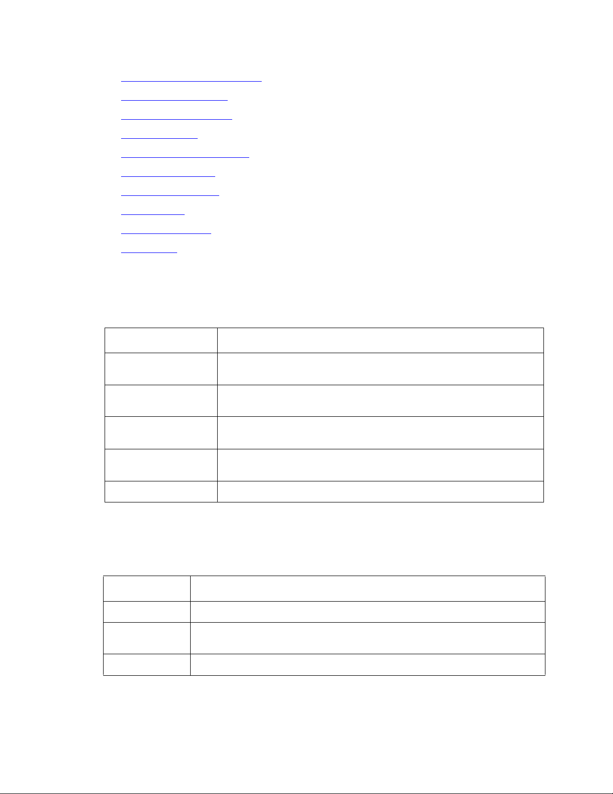
Input window actions: The following table describes the features of the input window.
Feature Action
Menu bar Pull down a list of actions, edit options, and online Help.
Toolbar action
buttons
Input fields Type in the information that is needed to complete an action.
Click a button to perform an action.
Selection list View a list of the content that you may enter in the input field.
Visual Vectors R14 User Guide February 2007
23
Page 24

Setting up the My World objects directory
Adding objects
You can add three types of objects from you call center network to the My World directory:
● CMS servers
● Vectors
● New scratchpads
Note:
Note: New CMS servers are added to the My World directory whenever you make an
initial connection to a CMS server. For more information, see Connecting to a
new CMS server on page 22.
To add a new vector or scratchpad to the My World directory (for example, a new vector for an
ACD in the Vector Folder), you must first select a container for the object in a Navigator window.
Note:
Note: If you add or save a vector to the Vector Folder on a measured ACD, it is also
added to the CMS database.
Procedure: To add a new vector or ScratchPad to the My World directory:
1. In the Navigator window, highlight a ScratchPad or Vector Folder in the left-hand pane,
and then click the right mouse button. The system displays the shortcut menu.
2. Do one of the following:
● If you selected a Vector Folder and are online select New from the shortcut list.
● If you selected a Vector Folder and are offline, select a vector type from the shortcut
list.
● If you selected a ScratchPad, select New from the shortcut menu.
The system displays the New Vector or New ScratchPad window.
3. Fill in the required information in the input fields in the window. For a new vector, you need
to enter a name. If you are adding a new vector to an ACD, an Id is also required.
4. Click OK.
If the addition was:
● Successful, the system displays the new object in the Navigator window.
● Not successful, the system displays an error message showing the cause of the
failure.
24 Visual Vectors R14 User Guide February 2007
Page 25

Deleting objects
Procedure
You may want to delete a CMS from the My World directory or a vector from the CMS
database.
Getting information
You may want to obtain additional information before you delete an object from the My World
directory.
To obtain information about the object before you delete it:
1. Select the object in the Navigator window and then do one of the following:
● Select Properties from the File menu or shortcut menu.
● Click the Properties icon on the toolbar.
Managing objects in the My World directory
● Press Alt+Enter.
The system displays the Properties window.
2. Locate and note the relevant information. For example, verify that you have permission to
delete the item.
Deleting an object
To delete a CMS server or vector listed in the My World directory:
1. Select the object in the Navigator window.
2. Do one of the following:
● Select Delete from the File menu or shortcut menu.
● Click the Delete icon on the toolbar.
● Press Delete.
If the deletion was:
-
Successful, the contents of the object (steps) are removed causing the vector to
not appear in Navigator.
-
Not successful, the system displays an error message showing the cause of the
failure.
Visual Vectors R14 User Guide February 2007
25
Page 26

Setting up the My World objects directory
Renaming objects
You may want to rename an object that already exists in the My World directory. You may need
to obtain information from the CMS database before renaming the item for future reference.
Getting information
To obtain information from the CMS database before you rename the item:
1. Select the object in the Navigator window and then do one of the following:
● Select Properties from the File menu or shortcut menu.
● Click Properties on the toolbar.
● Press Alt+Enter.
The system displays the Properties window.
2. Locate and note the relevant information. For example, verify the type of the vector you
want to rename.
3. Close the Properties window.
Doing the renaming
To rename an ACD object in the CMS database:
1. Select the object in the Navigator window.
2. Do one of the following:
● Select Rename from the File menu or shortcut menu.
● Click Rename on the toolbar.
The system displays the Renaming object window with the Name property field
highlighted.
3. Type in the new name or edit the existing name and then click OK.
If the object was
● Renamed, the system displays the new name in the Navigator window.
● Not renamed, the system displays an error message that shows the cause of the
failure.
26 Visual Vectors R14 User Guide February 2007
Page 27

Changing other object properties
Procedure: Use this procedure to change properties of one or more objects or entities, such as
a split/skills, vectors, VDNs, or trunk groups.
1. Select one or more object in the Navigator window and then do one of the following:
● Select Properties from the File menu or shortcut menu.
● Click Properties on the toolbar.
● Press Alt+Enter.
If a single object was selected, the system displays the Properties dialog. If multiple
objects were selected, the system displays the Properties of Many Objects dialog.
The window contains properties for the object or objects for which you have permissions in
the CMS Dictionary.
2. Type the new values in the fields you want to change.
The system displays a red box around any property fields with invalid values.
My World objects
3. When you have made all of your changes and no red boxes are displayed, click OK.
My World objects
Objects include items on which you can perform actions in the My World directory. For
example, the objects may be vectors, trunk groups, or ACDs.
No matter which tool you use to select an object, the way in which you perform an action on the
object is the same.
This section includes the following information:
● Defining My World objects on page 27
Defining My World objects
The following list includes possible objects in the My World directory. To perform actions on the
object, click the object using the right mouse button.
● My World object on page 28
● ScratchPad object on page 28
● CMS object on page 29
● ACD object on page 29
Visual Vectors R14 User Guide February 2007
27
Page 28
Setting up the My World objects directory
● Announcement Folder object on page 30
● Announcement object on page 30
● Split/Skill Folder object on page 30
● Split/Skill object on page 31
● Trunk Group Folder object on page 31
● Trunk Group object on page 31
● Vector Folder object on page 32
● Vector object on page 32
● VDN Folder object on page 33
● VDN object on page 33
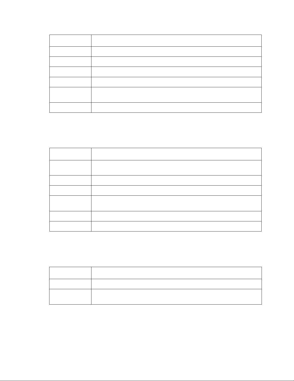
My World object
The following table describes the My World object:
Actions Description
Explore Expands My World to show one or more CMS Servers for which
Disconnect All Displays the Disconnect window with all connected CMS servers
Navigator Launches the Navigator window with the My World director as
New If the CMS submenu is clicked, accesses the New CMS window
Properties Displays the properties of the My World directory.
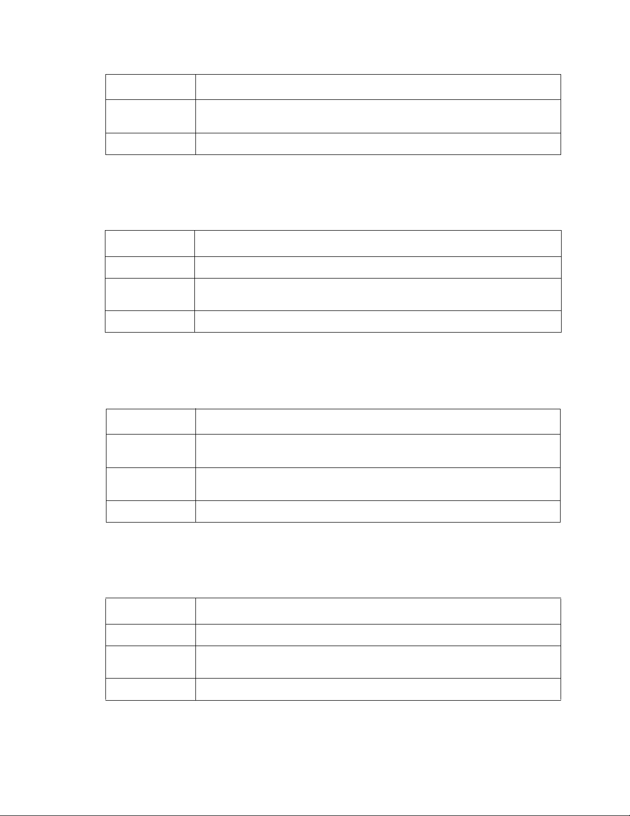
ScratchPad object
The following table describes the ScratchPad object:
Actions Description
Explore Expands the ScratchPad.
you have read or read and write permission.
highlighted.
the place to start browsing.
to add a new server to your world.
Navigator Launches the Navigator window with the ScratchPad as the place to
start browsing.
New Creates a new ScratchPad or new vectors.
28 Visual Vectors R14 User Guide February 2007
Page 29
Actions Description
Cut Cuts the selected ScratchPad, to be pasted later.
Copy Copies an object, to be pasted later.
Paste Pastes an object that has been cut or copied.
Delete Deletes the ScratchPad.
Rename Places the user in edit mode for the ScratchPad name field in the
Properties Displays the properties of the ScratchPad.
CMS object
The following describes the CMS object:
Actions Descriptions
My World objects
Renaming ScratchPad window.
Explore Expands the CMS object to show one or more ACDs for which you
Connect Displays the Connect to server window for this CMS.
Disconnect Displays the Disconnect window with this CMS highlighted.
Navigator Launches the Navigator window with the CMS as the place to start
Delete Removes the CMS from the My World directory.
Properties Displays the properties of the CMS.
ACD object
The following table describes the ACD object:
Actions Descriptions
Explore Expands the ACD object to show folders of CMS entities.
Navigator Launches the Navigator window with the ACD as the place to start
have read or read and write permission.
browsing.
browsing.
Visual Vectors R14 User Guide February 2007
29
Page 30
Setting up the My World objects directory
Actions Descriptions
Rename Places you in edit mode for the “ACD name” field in the Renaming
ACD window.
Properties Displays properties of the ACD.
Announcement Folder object
The following table describes the Announcement Folder object:
Actions Descriptions
Explore Expands the Announcement Folder.
Navigator Launches the Navigator window with the folder as the place to start
browsing.
Properties Displays the properties of the Announcement folder.
Announcement object
The following table describes the Announcement object:
Actions Descriptions
Navigator Launches the Navigator window with the announcement as the place
to start browsing.
Rename Places the user in edit mode for the “Announcement name” field in the
Renaming Announcement window.
Properties Displays the properties of the announcement.
Split/Skill Folder object
The following table describes the Split/Skill Folder object:
Actions Descriptions
Explore Expands the Split/Skill Folder.
Navigator Launches the Navigator window with the folder as place to start
browsing.
Properties Displays the properties of the Split/Skill Folder.
30 Visual Vectors R14 User Guide February 2007
Page 31

Split/Skill object
The following table describes the Split/Skill object:
Actions Descriptions
Navigator Launches the Navigator window with the split/skill as the place to start
browsing.
Rename Places user in edit mode for the “Split/Skill name” field in the Renaming
Split/Skill window.
Properties Displays the properties of the Split/Skill.
Trunk Group Folder object
The following describes the Trunk Group Folder object:
Actions Descriptions
My World objects
Explore Expands the Trunk Group Folder.
Navigator Launches the Navigator window with the folder as the place to start
Properties Displays the properties of the Trunk Group Folder.
Trunk Group object
The following describes the Trunk Group object:
Actions Descriptions
Navigator Launches Navigator window with the trunk group as place to start
Rename Places the user in edit mode for the “Trunk Group name” field in the
Properties Displays the properties of the Trunk Group.
browsing.
browsing.
Renaming Trunk Group window.
Visual Vectors R14 User Guide February 2007
31
Page 32

Setting up the My World objects directory
Vector Folder object
The following table describes the Vector Folder object:
Actions Descriptions
Explore Expands the Vector Folder.
Navigator Launches the Navigator window with the folder as place to start
browsing.
New Vector Creates a new vector with one Stop step in the folder.
Paste Pastes a vector if there is one cut or copied.
Properties Displays the properties of the Vector Folder.
Vector object
The following table describes the Vector object:
Actions Descriptions
Edit Accesses the Vector Editor tool to edit the vector.
Export Accesses the Import Export Wizard to export the vector.
Navigator Launches the Navigator window with the vector as the place to start
browsing.
Cut Copies a vector to memory and replaces it with a blank vector.
Copy Copies a vector to be pasted later.
Delete Deletes the vector from the folder for this ACD. This replaces it with a
blank vector and leaves the name in the Dictionary.
Rename Places the user in edit mode for the “Vector name” field in the
Renaming... window.
Properties Displays the properties of the vector.
32 Visual Vectors R14 User Guide February 2007
Page 33

VDN Folder object
The following table describes the VDN Folder object:
Actions Descriptions
Explore Expands the VDN folder.
Navigator Launches the Navigator window with the folder as the place to start
Properties Displays the properties of the VDN Folder.
VDN object
The following table describes the VDN object
Actions Descriptions
My World object properties
browsing.
Navigator Launches the Navigator window with the VDN as the place to start
browsing.
Rename Places the user in edit mode for the “VDN name” field in the Renaming
VDN window.
Properties Displays the properties of the VDN.
My World object properties
Use object properties to change certain parameters of:
● Any entities of the ACD, including announcements, splits or skills, trunk groups, VDNs,
and vectors
● VDN administration, for example, the assigned vector and skill preferences
This section includes the following information:
● Defining object properties on page 34
Visual Vectors R14 User Guide February 2007
33
Page 34

Setting up the My World objects directory
Defining object properties
The following table describes the properties of all objects in the My World directory. To perform
actions on the object, click the object using the right mouse button, and then select Properties.
● My World object on page 34
● ScratchPad object on page 35
● CMS object on page 35
● ACD object on page 35
● Announcement Folder object on page 36
● Announcement object on page 36
● Split/Skill Folder object on page 37
● Split/Skill object on page 37
● Trunk Group Folder object on page 38
● Trunk Group object on page 38
● Vector Folder object on page 38
● Vector object on page 39
● VDN Folder object on page 39
● VDN object on page 40
My World object
The following table describes properties of the My World object:
Properties Description
Name You cannot edit this name.
Type Type of object (World).
Permission Displays the permission (R for read) that you have for the My World
Description Description of My World object. You can edit this field.
directory.
34 Visual Vectors R14 User Guide February 2007
Page 35

ScratchPad object
The following describes properties of the ScratchPad object:
Properties Description
Name Name of a folder that contains offline vectors.
Type Type of object (ScratchPad).
Permission Displays ScratchPad permissions (R for read and W for write).
Description Characters describing the ScratchPad object. You can edit this field.
CMS object
The following describes properties of the CMS object:
Properties Description
My World object properties
Name Name of the CMS server. You cannot edit this name.
Type Type of object (CMS or unconnected CMS).
Permission Displays the permissions (R for read, blank for none) that you have for
Version If connected, displays CMS server software release and version
Locale If connected, displays CMS server software locale and time zone, for
Containee
Count
ACD object
The following table describes properties of the ACD object:
Properties Description
Name Name of the ACD in the CMS Dictionary. You can rename it if you
the CMS server.
numbers.
example, TZ GMT – 05:00.
If connected, displays the number of objects (ACDs) that are contained
within this object.
have ACD read and write access on the CMS.
Type Type of object (ACD).
Visual Vectors R14 User Guide February 2007
35
Page 36

Setting up the My World objects directory
Properties Description
Permission Displays the ACD permissions (read, write, or both) that you have on
the CMS.
Id Number that identifies the ACD on the CMS.
Version Communication server software release and version numbers.
Locale Switch software locale and time zone, for example, TZ GMT — 05:00.
Link Status Status (Link Up, Link Down) of the link to the ACD from the CMS. The
ACD icon is crossed out in the Navigator window if the link is down.
ACD Features Features enabled on the ACD, which could be EAS, Prompting, or
Vectoring.
Description Description of the ACD in the CMS Dictionary. You can edit this field.
Announcement Folder object
The following table describes properties of the Announcement Folder object:
Properties Description
Name Name of the folder that contains announcements for this ACD.
Type Type of object (folder).
Permission Displays the announcement permissions (read, write, or both), that you
have for this ACD.
Containee
Count
Shows the number of announcements that are contained in the folder.
Announcement object
The following describes properties of the Announcement object:
Properties Description
Name Name of the announcement in the CMS Dictionary. You can rename it
if you have read and write permissions.
Type Type of object (announcement).
Permission Displays the permissions (read, write, or both) that you have for this
announcement.
36 Visual Vectors R14 User Guide February 2007
Page 37

Properties Description
Extension Announcement extension number.
Description Description of the announcement in the CMS Dictionary. You can edit
this field.
Split/Skill Folder object
The following describes properties of the Split/Skill Folder object:
Properties Description
Name Name of the folder that contains measured splits or skills for this ACD.
Type Type of object (folder).
Permission Displays the split and skill permissions (read, write, or both) that you
have for this ACD.
My World object properties
Containee
Count
Split/Skill object
The following table describes properties of the Split/Skill object:
Properties Description
Name Name of the split/skill in the CMS Dictionary.
Type Type of object (split/skill).
Permission Displays the permissions (read, write, or both) that you have for this
Id Number identifying the split/skill on the CMS.
Description Description of the split/skill in the CMS Dictionary. You can edit this
Shows the number of splits or skills that are contained in the folder.
split/skill.
field.
Visual Vectors R14 User Guide February 2007
37
Page 38

Setting up the My World objects directory
Trunk Group Folder object
The following table describes properties of the Trunk Group Folder object:
Properties Description
Name Name of the folder that contains measured trunk groups for this ACD.
Type Type of object (folder).
Permission Displays the trunk group permissions (read, write, or both) that you
have for this ACD.
Containee
Count
Trunk Group object
The following table describes properties of the Trunk Group object:
Properties Description
Name Name of the trunk group in the CMS Dictionary.
Type Type of object (trunk group).
Permission Displays the permissions (read, write, or both) that you have for this
Id Number that identifies the trunk group on the CMS.
Description Description of the trunk group in the CMS Dictionary. You can edit this
Vector Folder object
Shows the number of trunk groups that are contained in the folder.
trunk group.
field.
The following table describes properties of the Vector Folder object:
Properties Description
Name Name of the folder that contains non-empty vectors for this ACD.
Type Type of object.
38 Visual Vectors R14 User Guide February 2007
Page 39

My World object properties
Properties Description
Permission Displays the vector permissions (read, write, or both) that you have for
this ACD.
Containee
Count
Vector object
The following table describes properties of the Vector object:
Properties Description
Name Name of the vector in the CMS Dictionary.
Type Type of object (vector).
Permission Displays the permissions (read, write, or both) that you have for
Description Description of the vector in the CMS Dictionary. You can edit this
Id Number that identifies the vector on the CMS.
Step Count The number of steps that are contained in the vector.
Shows the number of vectors that are contained in the folder.
this vector
field.
VDN Folder object
The following table describes properties of the VDN Folder object:
Properties Description
Name Name of the folder that contains measured VDNs for this ACD.
Type Type of object (folder).
Permission Displays the VDN permissions (read, write, or both) that you have for
Containee
Count
this ACD.
Shows the number of VDNs that are contained in the folder.
Visual Vectors R14 User Guide February 2007
39
Page 40

Setting up the My World objects directory
VDN object
The following table describes properties of the VDN object:
Properties Description
Name Name of the VDN in the CMS Dictionary.
Type Type of object (VDN).
Permission Displays the permissions (read, write, or both) that you have for this
VDN.
Extension VDN extension number.
Vector Id Shows the number or synonym that identifies the vector that is
assigned to this VDN. You can change this assignment if you have
VDN permissions on the CMS for the ACD.
Description Description of the VDN in the CMS Dictionary. You can edit this field.
Skill Pref Shows what skill preferences are assigned to this VDN. You can
change this assignment if you have VDN permissions on the CMS
for the ACD [Expert Agent Selection (EAS) only].
40 Visual Vectors R14 User Guide February 2007
Page 41

Using Visual Vectors Framework
This chapter explains how to use Visual Vectors Framework. It includes the following sections:
● Introduction to Visual Vectors Framework on page 41
Introduction to Visual Vectors Framework
This section provides an introduction to Visual Vectors Framework features and explains how to
use the Framework window.
This section includes the following information:
● Features of Visual Vectors Framework on page 41
● Connecting to CMS servers on page 42
● Framework window objects on page 43
Features of Visual Vectors Framework
Framework is the starting point of Visual Vectors. Framework gives you access to all of the
Visual Vectors features, which gives you the ability to manage any connections Visual Vectors
has to Call Management System (CMS) servers. For example, from the Framework window,
you can access Visual Vectors tools to view, modify, add, and delete ACD items in the CMS
database.
You can use the Framework window to begin the following tasks and activities:
● Connect to CMS servers
● Launch Avaya CMS Supervisor
● Use Navigator to view or modify the properties of objects in the My World directory
● Use Vector Editor to create new vectors or edit existing ones
● Use VDN Assignment Wizard to assign one or more VDNs to a vector
● Use Import Export Wizard to import vectors to a public directory or other application
No matter which tool you use to select an operation, the way in which you perform the operation
is the same.
Visual Vectors R14 User Guide February 2007 41
Page 42

Using Visual Vectors Framework
Connecting to CMS servers
You can connect to an existing server or establish a connection to a new server. You are limited
to one instance of a login ID per server, but you can connect to more than one server at a time.
Logging in to an existing server
Use this procedure if you have connected to a CMS server at least once.
1. Click Connect on the toolbar or select Connect from the File menu.
The system displays the Connect to Server dialog box showing the server to which you
connected last.
2. If you want to connect to a different server than the one that is displayed, select a CMS
server from the Connect to server: list.
3. Enter your CMS login Id in the Login Id: text box.
4. Enter your CMS password in the Password: text box.
5. Click Connect.
If the Disconnect toolbar button in Framework is highlighted, you have successfully logged
in to the CMS server.
Logging in to a new server
If you have never connected to a CMS server before, you need to establish a connection. To
connect to a new server:
1. Select Connect from the File menu.
The system displays the New CMS login dialog box.
2. Type the hostname or IP address of a CMS/Visual Vectors server in the Server Network
Address: text box.
3. Enter your CMS login ID in the Login Id: text box.
4. Type your CMS password in the Password text box.
5. Click OK.
If the CMS server you entered exists, you are connected to this new server. If the CMS
server does not exist, the system displays an error message showing the cause of the
failure.
42 Visual Vectors R14 User Guide February 2007
Page 43

Disconnecting from CMS servers
You do not have to disconnect from CMS servers before exiting Framework. The Visual Vectors
program disconnects your computer automatically before it closes the Framework window.
1. To disconnect from a server or servers, do one of the following:
● Select Disconnect from the Framework File menu.
● Click Disconnect in the Framework toolbar.
The system displays the Disconnect window.
2. Select the servers you want to disconnect from and then click Disconnect.
Framework window objects
This section introduces you to the features of the Framework window as they appear both
before and after you connect to a CMS server.
Introduction to Visual Vectors Framework
Title bar
The title bar shows the name of the tool. When a vector is open in the Vector Editor, its name is
shown.
Minimize, Maximize/Restore, and Close buttons
These buttons adjust the size of the current window, or close it.
Toolbar
The toolbar contains buttons for quick access to specific features of the application. When your
mouse pointer is over a toolbar button for a few seconds, a brief description of the button
displays. When you select a button, the status bar displays a description of the command that
the particular button performs.
The following table describes buttons on the toolbar.
Button Function
Connect Initiates a connection to a CMS server.
Disconnect Disabled until you are connected to a CMS server.
Navigator Accesses the window for the Navigator.
Vector Editor Accesses the window for the Vector Editor.
Visual Vectors R14 User Guide February 2007
43
Page 44

Using Visual Vectors Framework
Button Function
VDN
Assignment
Wizard
Import Export
Wizard
CMS
Supervisor
Help Contents Starts the Help application window for Visual Vectors.
Status bar
The status bar is located at the bottom of the Framework and Vector Editor windows.
Framework displays a brief description of what actions are occurring. Vector Editor displays the
number of steps in the current vector.
Menu bar
The menu bar lists the available drop-down menus. This section identifies the menus that are
available before you log in to the CMS server: File, Tools, Window, and Help.
Accesses the first of a series of dialog boxes for the VDN Assignment
Wizard.
Accesses the first of a series of dialog boxes for the Import Export
Wizard.
Starts CMS Supervisor Version 6 or later, if that program is installed
correctly. If not, this button does not appear.
File menu
Select File from the menu bar to display the File menu. The File menu has the following items:
● Connect – Displays the Connect to server window. You can select from the drop-down
list of servers to which you have previously connected, or click New CMS to identify a new
server to log in to and add to your My World directory.
● Disconnect – Displays the Disconnect window that lists the servers to which you are
connected. Highlight the server or servers from which you wish to disconnect and select
Disconnect or press Enter.
● Exit – Automatically disconnects your computer from any CMS servers to which you are
connected, and then closes the Framework window. The system displays a warning
message if you have open tool windows.
Tools Menu
Select Tools from the menu bar to display the Tools menu. The Tools menu has the following
items:
44 Visual Vectors R14 User Guide February 2007
Page 45

Introduction to Visual Vectors Framework
● Vector Editor – Opens the window for the Vector Editor. You can create new vectors or edit
existing vectors in this window, and then save them to an ACD if you have the needed
permissions or the ScratchPad on your computer.
● Navigator – Opens the window for the Navigator. You can view, add, delete, or move
objects in your Call Center World using this window.
● VDN Assignment Wizard – Opens the first of a series of dialog boxes for the VDN
Assignment Wizard. This tool helps you to assign VDNs to vectors and VDN skill
preferences. You can also view which VDNs are assigned to which vectors and, if
necessary, change those assignments.
● Import Export Wizard – Opens the first of a series of dialog boxes for the Import Export
Wizard. This tool helps you to create a vector file, which can contain one or more vector
objects. You can then export the vector file to a shared or public directory, where it can be
imported and shared by other users.
● CMS Supervisor – Launches a separate session of CMS Supervisor. The two programs
are autonomous. Supervisor appears only if you have the right version installed on your
computer.
● Advanced Debugging... – Used for debugging. Do not change the settings on the
Advanced window unless you are instructed to do so by an Avaya administrator.
Window menu
Select Window from the menu bar to display the Window menu. The Window menu has the
following items:
● Close All – Closes the windows of all open tools, but leaves the Framework window open
and the Visual Vectors software running.
● VDN Assignment Wizard – Makes the VDN Assignment Wizard the current window.
Help menu
Select Help from the menu bar to display the Help menu.
Press F1 or click Help to display help on a window or tool.
Help menu items: In the Help menu, you can select from the following options:
● Help Contents – Opens the Help window, and displays the Visual Vectors table of
contents.
● About… – Displays the About Visual Vectors… window, which shows the software build
number.
Visual Vectors R14 User Guide February 2007
45
Page 46

Using Visual Vectors Framework
46 Visual Vectors R14 User Guide February 2007
Page 47

Using Navigator
This chapter explains how to use the Visual Vectors Navigator feature, and familiarizes you with
the objects in the Navigator window.
This section includes the following topics:
● Features of Navigator on page 47
● Navigator window objects on page 47
Features of Navigator
You use Navigator to view and manage call center objects using the same conventions as you
use to manage Microsoft Windows Explorer. Navigator provides a means for you to:
● View and manage switch objects that are used in vectors.
● Use the offline ScratchPad to store vectors on your computer. If you have many vectors,
organize them into folders.
● Copy and move vectors from ScratchPad to one or more ACDs, and between ACDs.
● Change the properties of VDNs.
● View and rename objects, depending on your permissions.
Navigator window objects
This section introduces you to various features of the Navigator window as they appear both
before and after you connect to a CMS server.
This section includes the following topics:
● Status indicators on page 48
● Status messages on page 48
Visual Vectors R14 User Guide February 2007 47
Page 48

Using Navigator
Status indicators
The following table describes the indicators in Navigator. These indicators tell you about the
state of a CMS server and its measured ACDs.
This indicator Displays
Login status The icon for the CMS object in Navigator displays a black screen if you
ACD link status Icons for the ACDs that are supported by the CMS. If the link to an
Status messages
are not connected.
ACD is down, the icon is crossed out. If the CMS server is connected to
the ACD via a TCP/IP connection and the connection is in a transient
state, the icon changes to a straight line.
The following table describes the status messages that may display in Visual Vectors.
This message Displays when
Starting tool... A Visual Vectors window is opening. Framework is locked during this
time.
Looking for
items to
Connect...
Framework is searching the My World directory for CMS servers.
48 Visual Vectors R14 User Guide February 2007
Page 49

Using the Vector Editor
This chapter explains how to use the Vector Editor. It includes the following sections:
● Introduction to the Vector Editor on page 49
● Using Vector Editor windows on page 50
● Using vector steps on page 53
Introduction to the Vector Editor
This section provides an overview of the Visual Vectors Vector Editor. It also explains how to
open the Vector Editor, close windows, and exit the Vector Editor.
This section includes the following information:
● Vector Editor features on page 49
● Opening and closing the Vector Editor on page 50
● Vector Editor window objects on page 50
Vector Editor features
Vector Editor allows you to create and edit vectors using a graphical user interface (GUI) that
lets you drag and drop icons from a palette and arrange them into vector steps in a work area.
Vector Editor lets you:
● Create and edit vectors by an easy, drag-and-drop method
● Annotate, that is, attach comments to vectors
● Print representations of vectors
For users who are familiar with accessing vectors from a terminal, Navigator supplies a
read-only ascii text view for online vectors.
Visual Vectors R14 User Guide February 2007 49
Page 50

Using the Vector Editor
Opening and closing the Vector Editor
To open the Vector Editor:
1. Use the Framework toolbar to do one of the following:
● Select Vector Editor from the Tools menu or click the Vector Editor icon in the toolbar,
and then select a vector type from the Vector Editor menu.
● Double-click on a vector in Navigator to start the Vector Editor.
Vector Editor window objects
Using the Vector Editor window, you can create and edit vectors visually using common
Windows-based conventions. For example, you can use the drag-and-drop method to move
icons that represent commands from a palette and arrange them into vector steps in a work
area. You can also attach comments, change layout, and save and print the vectors.
Status indicators: The following table describes status indicators:
Indicator Function
Vector
Location
Shows New Vector or a full path to an existing vector in the My World
directory (for example, /My World/CMS20/ACD8/Vector Folder/Visual
Vector).
Current
Visual Steps
Current
Stored
Steps
Shows a count of the number of palette icons in the current visual vector.
The initial Start icon is not counted.
Shows a count of the number of vector steps the current vector will
occupy when stored on an ACD. The limit is 99 steps. At step 96, the line
stating the number of steps turns yellow. At step 100, the line turns red.
Using Vector Editor windows
This section introduces you to the features of the Vector Editor window. Follow the instructions
to select menu items and enter values in input fields in Vector Editor dialog boxes.
This section includes the following information:
● Accessing vectors on page 51
● Saving and printing vectors on page 51
50 Visual Vectors R14 User Guide February 2007
Page 51

Accessing vectors
Methods used to access vectors
You can access vectors from the Navigator window or from the Vector Editor.
Accessing vectors from Navigator
To access vectors from the Navigator window:
1. In the Framework window, select Navigator from the Tools menu, or click the Navigator
icon in the toolbar.
The system displays the Navigator window.
2. Browse the My World directory to find the object you want.
3. When you find the object you want, such as the ScratchPad or an ACD Vector Folder in
the Navigator window, double-click it. The objects contained in the folder appear in the
right pane of the Navigator window.
Using Vector Editor windows
4. Double-click the vector to open it.
The Vector Editor opens the vector.
Accessing vectors from Vector Editor
To access a vector from the Vector Editor window:
1. Select Open... from the Vector Editor File menu.
The system displays the Select the Vector to open window.
2. Browse the My World directory to find the vector you want to open.
3. Double-click the vector you want to open.
Saving and printing vectors
Procedure
To save a vector from the Vector Editor window:
1. Select Save As... from the File menu.
The Vector Editor displays the Save Vector As window.
Visual Vectors R14 User Guide February 2007
51
Page 52

Using the Vector Editor
2. Browse the My World directory to find the container in which you want to save the current
vector.
3. Click the name of the container (ScratchPad or Vector Folder) in which you want to save
the vector.
4. If you want to give the vector a name that is different from the default name, type your
preferred name in the Name text box.
5. Click Save.
The Vector Editor does one of the following:
● Saves a graphical representation of the selected vector to the ScratchPad
● Converts the visual vector and stores it on the ACD containing the Vector Folder
Saving vectors in Navigator
In Navigator, you can drag and drop vectors into the container in which you want to save them.
Printing vector graphics
The print function is available only in the Vector Editor. To print a vector graphic:
1. Select Print from the File menu in the Vector Editor window.
The system displays the Print dialog box.
2. In the Print dialog box, select the printer, print range, and number of copies.
3. If you need to specify any printer properties, click Properties and make your changes in
the Document Properties window. Then click OK.
4. In the Print dialog box, click OK.
The system displays the Printing Properties window.
5. The Printing Properties window lets you scale your printed graphic.
Select any of the following print options:
● 1 to 1: Your vector graphic will print as the size you see on your screen. This is the
default option.
● fit to 1 page: Your vector graphic will print on one page.
● fit to pages wide: Your vector graphic will print on the number of pages you specify in
the pages field. The printed graphic will remain height and width proportional.
● fits to pages high: Your vector graphic will print on the number of pages you specify in
the pages field. The printed graphic will remain height and width proportional.
● scale to percent: Your vector graphic will print to the size you specify in the % field. The
printed graphic will remain height and width proportional.
52 Visual Vectors R14 User Guide February 2007
Page 53

● Step Labels: Click to enable the printing of step labels that are present on your vector
graphic. If there are no step labels, this field is unavailable.
● Floating Comments: Click to enable the printing of global comments that are present
on your vector graphic. If there are no global comments, this field is unavailable.
● Step Comments: Click to enable the printing of step comments that are present on
your vector graphic. If there are no step comments, this field is unavailable.
● Alignment: Allows you to determine the positioning of the vector graphic on the
printout.
6. Click OK in the Printing Properties window to print your vector graphic.
Using vector steps
This section lists the vector steps in the Vector Editor palettes and describes all possible step
properties.
Using vector steps
This section includes the following information:
● Vector step palettes on page 53
● Vector step properties on page 55
● Creating a new Goto vector on page 75
● Moving or copying vectors to ACDs of different types on page 81
● Commenting and uncommenting vector steps on page 82
Vector step palettes
Vector steps are grouped in the following five palettes on the left side of the Vector Editor
window. Note that not all the steps are available for every type of vector. For example, the
collect step is not available for nonprompting vectors.
● Input/Output
-
Announcement
-
Timed Announcement
-
Music
-
Ringback
-
Silence
-
Reply
-
Consider
Visual Vectors R14 User Guide February 2007
53
Page 54

Using the Vector Editor
-
Collect
-
Converse
-
Set
● End
-
Busy
-
Stop
-
Disconnect
-
Return
● Te st
-
Caller Info
-
Center Info
-
Queue Activity
-
Agent Activity
-
Time of Day
-
Holiday
-
Variable
-
Media-Gateway/Port-Network
-
Server
-
Service Hours
● Queue
-
Queue Activity
-
Center Info
-
Agent Activity
-
Queue Unconditional
● Routing
-
Route To Number
-
Route To Digits
-
Adjunct Route
-
Messaging Skill
-
Goto Vector.
54 Visual Vectors R14 User Guide February 2007
Page 55

Vector step properties
When you select properties from the shortcut menu for an object, the system displays an input
window. The information that is required in the input window depends on the object.
This section describes all possible properties. However, not all features automatically show.
Which properties are shown, which menu items are available, and which toolbar buttons
function can vary from user to user.
The following properties are described:
● Announcement (Input/Output) step properties on page 56
● Timed Announcement (Input/Output) step properties on page 56
● Music (Input/Output) step properties on page 57
● Ringback (Input/Output) step properties on page 57
● Silence (Input/Output) step properties on page 58
● Reply (Input/Output) step properties on page 58
Using vector steps
● Consider (Input/Output) step properties on page 58
● Collect (Input/Output) step properties on page 59
● Converse (Input/Output) step properties on page 60
● Set (Input/Output) step on page 61
● Busy (End) step properties on page 62
● Stop (End) step properties on page 62
● Disconnect (End) step on page 63
● Return (End) step on page 63
● Caller Info (Test) step properties on page 63
● Center Info (Test) step properties on page 64
● Queue Activity (Test) step properties on page 65
● Agent Activity (Test) step properties on page 66
● Variable (Test) step on page 68
● Media-Gateway/Port-Network registration (Test) step on page 68
● Server (Test) step on page 69
● Service Hour (Test) step on page 69
● Queue Activity (Queue) step properties on page 69
● Center Info (Queue) step properties on page 70
● Agent Activity (Queue) step properties on page 71
Visual Vectors R14 User Guide February 2007
55
Page 56

Using the Vector Editor
● Queue Unconditional (Queue) step properties on page 72
● Route To Number (Routing) step properties on page 73
● Route To Digits (Routing) step properties on page 73
● Adjunct Route (Routing) step properties on page 74
● Messaging Skill (Routing) step properties on page 74
● Goto Vector (Routing) step on page 75
Announcement (Input/Output) step properties
Announcement (Input/Output) step includes the following properties:
Properties Description
Announcement Extension is always selected. There are no other settings.
Extension Enter a:
● 1 to 5 digit number (R10 or earlier), or
● 1 to 7 digit number (R11 or later), or
● A to Z, and V1 to V5 (CMS R13/Communication Manager 3.0 or
later), or
● AA to ZZ , and V1 to V9 (CMS R14/Communication Manager 4.0 or
later)
Description Enter a description that is associated with this step.
Comment Select Yes to comment out this step, or No to not comment out this
step.
Timed Announcement (Input/Output) step properties
Timed Announcement (Input/Output) step includes the following properties:
Properties Description
Seconds Enter a numeric value from 0 to 999.
Announcement Extension is always selected. There are no other settings.
56 Visual Vectors R14 User Guide February 2007
Page 57

Properties Description
Extension Enter a:
● 1 to 5 digit number (R10 or earlier), or
● 1 to 7 digit number (R11 or later), or
● A to Z, and V1 to V5 (CMS R13/Communication Manager 3.0 or
later), or
● AA to ZZ , and V1 to V9 (CMS R14/Communication Manager 4.0 or
later)
Disabled if Announcement is not tied to an Extension.
Treatment Select music, silence, ringback, or continue. The default is continue.
Description Enter a description that is associated with this step.
Comment Select Yes to comment out this step, or No to not comment out this
step.
Music (Input/Output) step properties
Using vector steps
The following table describes the Music (Input/Output) step:
Properties Description
Seconds Enter a numeric value from 0 to 999.
Description Enter a description that is associated with this step.
Comment Select Yes to comment out this step, or No to not comment out this
step.
Ringback (Input/Output) step properties
Ringback (Input/Output) step includes the following properties:
Properties Description
Seconds Enter a numeric value from 0 to 999.
Description Enter a description that is associated with this step.
Comment Select Yes to comment out this step, or No to not comment out this
step.
Visual Vectors R14 User Guide February 2007
57
Page 58

Using the Vector Editor
Silence (Input/Output) step properties
Silence (Input/Output) step includes the following properties:
Properties Description
Seconds Enter a numeric value from 0 to 999.
I-Silent Select to enable the I-Silent feature.
Description Enter a description that is associated with this step.
Comment Select Yes to comment out this step, or No to not comment out this
step.
Reply (Input/Output) step properties
Reply (Input/Output) step includes the following properties:
Properties Description
Description Enter a description that is associated with this step.
Comment Select Yes to comment out this step, or No to not comment out this
step.
Consider (Input/Output) step properties
Consider (Input/Output) step includes the following properties:
Properties Description
Measure Split/Skill is the default value. Select a location from the drop-down list,
if applicable.
Split/Skill Select a split, skill, or ID (or First, Second, or Third if EAS) from the
drop-down list. This field is disabled if the value in the Measure field is
Location.
Skill Id If connecting to a pre-Communication Manager 2.0 switch, enter a
numeric value from 1 to 999.
If connecting to a Communication Manager 2.0 or later switch, enter a
numeric value from 1 to 2000.
This field is disabled if the value in the Measure field is Location or if
the Split/Skill field is not Id. If you are in working offline (for example, in
a ScratchPad vector), you can also enter synonyms, but once you go
online you can only use numbers.
58 Visual Vectors R14 User Guide February 2007
Page 59

Using vector steps
Properties Description
Priority High is the default, or select low, medium, or top from the drop-down
list. This field is disabled if the value in the Measure field is Location.
Location Enter a:
● 1 to 5 digit number (R10 or earlier), or
● 1 to 7 digit number (R11 or later), or
● A to Z, and V1 to V5 (CMS R13/Communication Manager 3.0 or
later), or
● AA to ZZ , and V1 to V9 (CMS R14/Communication Manager 4.0
or later)
This field is disabled if the value in the Measure field is Split/Skill.
Adjustment Enter a:
● 1 to 5 digit number (R10 or earlier), or
● 1 to 7 digit number (R11 or later), or
● A to Z, and V1 to V5 (CMS R13/Communication Manager 3.0 or
later), or
● AA to ZZ , and V1 to V9 (CMS R14/Communication Manager 4.0
or later)
Description Enter a description that is associated with this step.
Comment Select Yes to comment out this step, or No to not comment out this
step.
Collect (Input/Output) step properties
Collect (Input/Output) step includes the following properties:
Properties Description
Source Digits is the default, or select CED or CDPD from the drop-down list, if
applicable.
Number of
digits
For Enter none, or a variable.
Enter a numeric value from 1 to 16. This field is disabled if the Source
field is not digits.
Variables can be:
● A to Z (CMS R12/Communication Manager 2.0 or later), or
● V1 to V5 (CMS R13/Communication Manager 3.0 or later), or
● AA to ZZ and V1 to V9 (CMS R14/Communication Manager 4.0 or
later)
Visual Vectors R14 User Guide February 2007
59
Page 60

Using the Vector Editor
Properties Description
Description Enter a description that is associated with this step.
Comment Select Yes to comment out this step, or No to not comment out this
step.
Converse (Input/Output) step properties
Converse (Input/Output) step includes the following properties:
Properties Description
Split/Skill Select a split/skill (First, Second, Third or Id) from the drop-down list.
Skill Id If connecting to a pre-Communication Manager 2.0 switch, enter a
numeric value from 1 to 999.
If connecting to a Communication Manager 2.0 or later switch, enter a
numeric value from 1 to 2000.
This field is disabled if the value in the Split/Skill field is not set to Id. If
you are in working offline (for example, in a ScratchPad vector), you
can also enter synonyms, but once you go online you can only use
numbers.
Priority High is the default, or select low, medium, or top from the drop-down
list.
Passing None is the default value.
Select vdn, ani, digits, qpos, wait, data, or variable (CMS R13/
Communication Manager 3.0 or later) from the drop-down list.
Variables can be:
● A to Z and V1-V5 (CMS R13/Communication Manager 3.0 or later),
or
● AA to ZZ and V1 to V9 (CMS R14/Communication Manager 4.0 or
later)
Data Enter a 1 to 6 digit number or variables if applicable.
Variables can be:
● A to Z and V1-V5 (CMS R13/Communication Manager 3.0 or later),
or
● AA to ZZ and V1 to V9 (CMS R14/Communication Manager 4.0 or
later)
This field is enabled only if the value in the first Passing field is Data.
60 Visual Vectors R14 User Guide February 2007
Page 61

Properties Description
Passing None is the default value.
Select vdn, ani, digits, qpos, wait, data, or variable (CMS R13/
Communication Manager 3.0 or later) from the drop-down list.
Variables can be:
● A to Z and V1-V5 (CMS R13/Communication Manager 3.0 or later),
or
● AA to ZZ and V1 to V9 (CMS R14/Communication Manager 4.0 or
later)
If the first Passing field value is None, then the only valid value for this
second Passing property is None.
Data Enter a numeric value from 0 to 100, or a variable.
Variables can be:
● A to Z and V1-V5 (CMS R13/Communication Manager 3.0 or later),
or
● AA to ZZ and V1 to V9 (CMS R14/Communication Manager 4.0 or
later)
This field is enabled if the value in the second Passing field is Data.
Using vector steps
Description Enter a description that is associated with this step.
Comment Select Yes to comment out this step, or No to not comment out this
step.
Set (Input/Output) step
Set step (CMS R13.1/Communication Manager 3.1 or later) includes the following properties:
Properties Description
Digits/Variable Enter digits or variables from AA to ZZ.
Operand 1 Enter digits, none, or a variable.
Variables can be:
● A to Z and V1-V5 (CMS R13/Communication Manager 3.0 or later),
● AA to ZZ and V1 to V9 (CMS R14/Communication Manager 4.0 or
Operator Select ADD, SUB, MUL, DIV, CATR, CATL, MOD10 or SEL
or
later)
Visual Vectors R14 User Guide February 2007
61
Page 62

Using the Vector Editor
Properties Description
Operand 2 Enter 0 - 9, none, digits or a variable.
Variables can be:
● A to Z and V1-V5 (CMS R13/Communication Manager 3.0 or later),
or
● AA to ZZ and V1 to V9 (CMS R14/Communication Manager 4.0 or
later)
Description Enter a description that is associated with this step.
Comment Select Yes to comment out this step, or No to not comment out this
step.
Busy (End) step properties
The Busy (End) step includes the following properties:
Properties Description
Description Enter a description that is associated with this step.
Comment Select Yes to comment out this step, or No to not comment out this
step.
Stop (End) step properties
Stop (End) step includes the following properties:
Properties Description
Description Enter a description that is associated with this step.
Comment Select Yes to comment out this step, or No to not comment out this
step.
62 Visual Vectors R14 User Guide February 2007
Page 63

Disconnect (End) step
Disconnect (End) step includes the following properties:
Properties Description
Description Enter a description that is associated with this step.
Comment Select Yes to comment out this step, or No to not comment out this
step.
Return (End) step
Return step (CMS R13.1/Communication Manager 3.1 or later) includes the following
properties:
Properties Description
Description Enter a description that is associated with this step.
Using vector steps
Comment Select Yes to comment out this step, or No to not comment out this
step.
Caller Info (Test) step properties
Caller Info (Test) step includes the following properties:
Properties Description
Measure ANI is the default, or select digits or ii-digits from the drop-down list, if
applicable.
Comparator Equals (=) is the default, or select <=, <>, <, >, >=, in, or not in, from
the drop-down list.
Threshold Enter a numeric value for ani or ii-digits (?, +, and # are valid in certain
situations), or a variable.
Variables can be from:
● A to Z and V1 to V5 (CMS R13/Communication Manager 3.0 or
later)
● AA to ZZ and V1 to V9 (CMS R14/Communication Manager 4.0 or
later)
This field is enabled only if the value in the Comparator field is "in" or
"not in."
Visual Vectors R14 User Guide February 2007
63
Page 64

Using the Vector Editor
Properties Description
Table Enter a numeric value from 1 to 100. This field is disabled if the value
in the Comparator field is anything except in or not in.
Description Enter a description that is associated with this step.
Comment Select Yes to comment out this step, or No to not comment out this
step.
Center Info (Test) step properties
Center Info (Test) step includes the following properties:
Properties Description
Measure Counted-calls to VDN is the default, or select rolling-asa or
expected-wait from the drop-down list.
Split/Skill Select a split/skill (First, Second, Third, Best, Call, or Id) from the
drop-down list. This field is disabled if the value in the Measure field is
not expected wait.
Skill Id If connecting to a pre-Communication Manager 2.0 switch, enter a
numeric value from 1 to 999.
If connecting to a Communication Manager 2.0 or later switch, enter a
numeric value from 1 to 2000.
This field is disabled if the value in the Split/Skill field is not Id. If you
are in working offline (for example, in a ScratchPad vector), you can
also enter synonyms, but once you go online you can only use
numbers.
Priority High is the default, or select low, medium, or top from the drop-down
list. This field is disabled if the value in the Measure field is not
expected wait, or if the value in the Split/Skill field is Best or Call.
VDN Select a VDN (or extension, active, or latest) from the drop-down list.
This field is disabled if the value in the Measure field is expected wait.
Extension Enter a 1 to 5 digit extension number (R10 or earlier)
or 1 to 7 digit number (R11 or later).
This field is disabled if the value in the VDN field is not an extension.
Comparator Equals (=) is the default value. Select <=, <>, <, >, >=, from the
drop-down list.
64 Visual Vectors R14 User Guide February 2007
Page 65

Properties Description
Threshold One (1) is the default value.
Or enter a numeric value that depends on the Measure and the
software version of your switch, or variables.
Variables can be from:
● A to Z and V1 to V5 (CMS R13/Communication Manager 3.0 or
later)
● AA to ZZ and V1 to V9 (CMS R14/Communication Manager 4.0 or
later)
Description Enter a description that is associated with this step.
Comment Select Yes to comment out this step, or No to not comment out this
step.
Queue Activity (Test) step properties
Queue Activity (Test) step includes the following properties:
Using vector steps
Properties Description
Measure Rolling-asa is the default value. Select calls-queued, interflow-qpos,
oldest-call-wait, or wait-improved from the drop-down list.
Split/Skill Select a split/skill (First, Second, Third, Id, or Best) from the drop-down
list. Disabled if Measure is interflow-qpos. Best is invalid if Measure is
anything but wait-improved.
Skill Id If connecting to a pre-Communication Manager 2.0 switch, enter a
numeric value from 1 to 999.
If connecting to a Communication Manager 2.0 or later switch, enter a
numeric value from 1 to 2000.
This field is disabled if the value in the Split/Skill field is not Id. If you
are in working offline (for example, in a ScratchPad vector), you can
also enter synonyms, but once you go online you can only use
numbers.
Priority High is the default, or select low, medium, or top from the drop-down
list. This field is disabled if the value in the Measure field is
interflow-qpos.
Comparator Equals (=) is the default, or select <=, <>, <, >, >=, from the drop-down
list.
Visual Vectors R14 User Guide February 2007
65
Page 66

Using the Vector Editor
Properties Description
Threshold One (1) is the default.
Or enter a numeric value that depends on Measure and the software
version of your switch. The maximum value is 2000.
Or enter a variable.
Variables can be from:
● A to Z and V1 to V5 (CMS R13/Communication Manager 3.0 or
later)
● AA to ZZ and V1 to V9 (CMS R14/Communication Manager 4.0 or
later)
Description Enter a description that is associated with this step.
Comment Select Yes to comment out this step, or No to not comment out this
step.
Agent Activity (Test) step properties
Agent Activity (Test) step includes the following properties:
Properties Description
Measure Available-agents is the default, or select staffed-agents from the
drop-down list.
Split/Skill Select a split/skill (First, Second, Third, or Id) from the drop-down list.
Skill Id If connecting to a pre-Communication Manager 2.0 switch, enter a
numeric value from 1 to 999.
If connecting to a Communication Manager 2.0 or later switch, enter a
numeric value from 1 to 2000.
This field is disabled if the value in the Split/Skill field is not Id. If you
are in working offline (for example, in a ScratchPad vector), you can
also enter synonyms, but once you go online you can only use
numbers.
Comparator Equals (=) is the default, or select <=, <>, <, >, >=, from the drop-down
list.
Threshold Zero (0) is the default value.
Or enter a numeric value that depends on Comparator and the
software version of your switch, or a variable.
Variables can be from:
● A to Z and V1 to V5 (CMS R13/Communication Manager 3.0 or
later)
● AA to ZZ and V1 to V9 (CMS R14/Communication Manager 4.0 or
later)
66 Visual Vectors R14 User Guide February 2007
Page 67

Properties Description
Description Enter a description that is associated with this step.
Comment Select Yes to comment out this step, or No to not comment out this
step.
Time Of Day (Test) step properties
Time Of Day (Test) step includes the following properties:
Properties Description
Start Day All is the default, or select beginning day from the drop-down list. Must
select All if Finish Day is All.
Start Time Current time is the default. Or enter the beginning time of day in
24-hour format.
Finish Day All is the default, or select the ending day from the drop-down list. Must
select All if Start Day is All.
Using vector steps
Finish Time Current time is the default. Or enter the ending time of day in 24-hour
format.
Description Enter a description that is associated with this step.
Comment Select Yes to comment out this step, or No to not comment out this
step.
Holiday (Test) step properties
Holiday (Test) step includes the following properties:
Properties Description
Comparator In is the default, or select not-in from the drop-down list.
Table Enter a numeric value from 1 to 9 (pre-CMS R13/Communication
Manager 3.0) or 1 to 99 (CMS R13/Communication Manager 3.0 or
later).
Description Enter a description that is associated with this step.
Comment Select Yes to comment out this step, or No to not comment out this
step.
Visual Vectors R14 User Guide February 2007
67
Page 68

Using the Vector Editor
Variable (Test) step
Variable step (CMS R13.1/Communication Manager 3.1 or later) includes the following
properties:
Properties Description
Measure Select Alphabet or Alphanumeric.
Comparator Enter <, >, =, <=, >=, <>, in, or not-in.
Threshold Depending on the value selected in Measure, enter:
● None, or
● 1 - 16 digits, or
● +, or
● #, or
● a variable
Variables can be from:
● A to Z and V1 to V5 (CMS R13/Communication Manager 3.0 or
later)
● AA to ZZ and V1 to V9 (CMS R14/Communication Manager 4.0
or later)
Description Enter a description that is associated with this step.
Comment Select Yes to comment out this step, or No to not comment out this
step.
Media-Gateway/Port-Network registration (Test) step
Media-Gateway/Port-Network registration step (CMS R13.1/Communication Manager 3.1 or
later) includes the following properties:
Properties Description
Measure Select Media-Gateway or Port-Network.
Comparator Enter either = or <>.
Value Enter 1 - 250, any or all if Measure is Media-Gateway, 1 - 64, any or all
if Measure is Port-Network.
Status String display "Registered."
Description Enter a description that is associated with this step.
Comment Select Yes to comment out this step, or No to not comment out this
step.
68 Visual Vectors R14 User Guide February 2007
Page 69

Server (Test) step
Server step (CMS R13.1/Communication Manager 3.1 or later) includes the following
properties:
Properties Description
Comparator Enter either = or <>.
Value Select main, ess, or lsp.
Description Enter a description that is associated with this step.
Comment Select Yes to comment out this step, or No to not comment out this
step.
Service Hour (Test) step
Service Hour (Test) step includes the following properties:
Using vector steps
Properties Description
Extension Enter a:
● 1 to 5 digit number (R10 or earlier), or
● 1 to 7 digit number (R11 or later), or
● A to Z, and V1 to V5 (CMS R13/Communication Manager 3.0 or
later), or
● AA to ZZ , and V1 to V9 (CMS R14/Communication Manager 4.0 or
later)
Description Enter a description that is associated with this step.
Comment Select Yes to comment out this step, or No to not comment out this
step.
Queue Activity (Queue) step properties
Queue Activity (Queue) step includes the following properties:
Properties Description
Measure Rolling-asa is the default, or select calls-queued, oldest-call-wait, or
wait-improved from the drop-down list.
Split/Skill Select a split/skill (First, Second, Third, Id, or Best) from the drop-down
list. Best is valid only if Measure is wait-improved.
Visual Vectors R14 User Guide February 2007
69
Page 70

Using the Vector Editor
Properties Description
Skill Id If connecting to a pre-Communication Manager 2.0 switch, enter a
Priority High is the default, or select Low, Medium, or Top from the drop-down
Comparator Auto-selected default. This is a read-only field.
Threshold One (1) is the default.
numeric value from 1 to 999.
If connecting to a Communication Manager 2.0 or later switch, enter a
numeric value from 1 to 2000.
This field is disabled if the value in the Split/Skill field is not set to Id. If
you are in working offline (for example, in a ScratchPad vector), you
can also enter synonyms, but once you go online you can only use
numbers.
list. This field is disabled if the value in the Split/Skill field is Best.
Or enter a numeric value that depends on Measure and the software
version of your switch, or a variable.
Variables can be from:
● A to Z and V1 to V5 (CMS R13/Communication Manager 3.0 or
later)
● AA to ZZ and V1 to V9 (CMS R14/Communication Manager 4.0 or
later)
Description Enter a description that is associated with this step.
Comment Select Yes to comment out this step, or No to not comment out this
step.
Center Info (Queue) step properties
Center Info (Queue) step includes the following properties:
Properties Description
Measure Expected-wait is the available value.
Split/Skill Select a split/skill (First, Second, Third, Best, or Id) from the drop-down
list.
Skill Id If connecting to a pre-Communication Manager 2.0 switch, enter a
numeric value from 1 to 999.
If connecting to a Communication Manager 2.0 or later switch, enter a
numeric value from 1 to 2000.
This field is disabled if the value in the Split/Skill field is not Id. If you are
in working offline (for example, in a ScratchPad vector), you can also
enter synonyms, but once you go online you can only use numbers.
70 Visual Vectors R14 User Guide February 2007
Page 71

Using vector steps
Properties Description
Priority Low is the default, or select Medium, High, or Top from the drop-down
list. This field is disabled if the value in the Split/Skill field is Best.
Comparator Auto-selected default. This is a read-only field.
Threshold One (1) is the default.
Or enter a numeric value that depends on Measure and the software
version of your switch, or a variable.
Variables can be from:
● A to Z and V1 to V5 (CMS R13/Communication Manager 3.0 or
later)
● AA to ZZ and V1 to V9 (CMS R14/Communication Manager 4.0 or
later)
Description Enter a description that is associated with this step.
Comment Select Yes to comment out this step, or No to not comment out this
step.
Agent Activity (Queue) step properties
The following table describes the Agent Activity (Queue) step:
Properties Description
Measure Available-agents is the default, or select staffed-agents from the
drop-down list.
Split/Skill Select a split/skill (First, Second, Third, or Id) from the drop-down list.
Skill Id If connecting to a pre-Communication Manager 2.0 switch, enter a
numeric value from 1 to 999.
If connecting to a Communication Manager 2.0 or later switch, enter a
numeric value from 1 to 2000.
This field is disabled if the value in the Split/Skill field is not set to Id. If
you are in working offline (for example, in a ScratchPad vector), you
can also enter synonyms, but once you go online you can only use
numbers.
Priority Low is the default, or select medium, high, or top from the drop-down
list.
Comparator Auto-selected default. This is a read-only field.
Visual Vectors R14 User Guide February 2007
71
Page 72

Using the Vector Editor
Properties Description
Threshold Zero (0) is the default. Or enter a numeric value that depends on the
Comparator value and the software version of your switch, or a
variable.
Variables can be from:
● A to Z and V1 to V5 (CMS R13/Communication Manager 3.0 or
later)
● AA to ZZ and V1 to V9 (CMS R14/Communication Manager 4.0 or
later)
Description Enter a description that is associated with this step.
Comment Select Yes to comment out this step, or No to not comment out this
step.
Queue Unconditional (Queue) step properties
Queue Unconditional (Queue) step includes the following properties:
Properties Description
Split/Skill Select a split/skill (First, Second, Third, Id, or Best) from the drop-down
list.
Skill Id If connecting to a pre-Communication Manager 2.0 switch, enter a
numeric value from 1 to 999.
If connecting to a Communication Manager 2.0 or later switch, enter a
numeric value from 1 to 2000.
This field is disabled if the value in the Split/Skill field is not set to Id. If
you are in working offline (for example, in a ScratchPad vector), you
can also enter synonyms, but once you go online you can only use
numbers.
Priority High is the default, or select low, medium, or top from the drop-down
list. This field is disabled if the value in the Split/Skill field is Best.
Description Enter a description that is associated with this step.
Comment Select Yes to comment out this step, or No to not comment out this
step.
72 Visual Vectors R14 User Guide February 2007
Page 73

Route To Number (Routing) step properties
The following describes the Route To Number (Routing) step:
Properties Description
Number Enter
● A 1 to 16 digit number, or
● Other valid characters, including *, #, ~p, ~w, ~W, ~m, ~s, and ~r.
The ~r character string can only be used at the beginning and has
to be followed by numbers only, or
● A variable
Variables can be from:
● A to Z and V1 to V5 (CMS R13/Communication Manager 3.0 or
later)
● AA to ZZ and V1 to V9 (CMS R14/Communication Manager 4.0
or later)
Coverage No is the default, or select yes from the drop-down list.
Using vector steps
Description Enter a description that is associated with this step.
Comment Select Yes to comment out this step, or No to not comment out this
step.
Route To Digits (Routing) step properties
Route To Digits (Routing) step includes the following properties:
Properties Description
Coverage No is the default, or select yes from the drop-down list.
Description Enter a description that is associated with this step.
Comment Select Yes to comment out this step, or No to not comment out this
step.
Visual Vectors R14 User Guide February 2007
73
Page 74

Using the Vector Editor
Adjunct Route (Routing) step properties
Adjunct Route (Routing) step includes the following properties:
Properties Description
Extension
Enter a 1-5 digit number.
(Release 10 or
earlier)
CTI-Link ID
(Release 11 or
later)
Enter a 1 to 64 digit CTI-Link Id number, or a variable.
Variables can be from:
● A to Z and V1 to V5 (CMS R13/Communication Manager 3.0 or
later)
● AA to ZZ and V1 to V9 (CMS R14/Communication Manager 4.0 or
later)
Description Enter a description that is associated with this step.
Comment Select Yes to comment out this step, or No to not comment out this
step.
Messaging Skill (Routing) step properties
Messaging Skill (Routing) step includes the following properties:
Properties Description
Split/Skill Select a split/skill (First, Second, Third, or Id) from the drop-down list.
Skill Id If connecting to a pre-Communication Manager 2.0 switch, enter a
numeric value from 1 to 999.
If connecting to a Communication Manager 2.0 or later switch, enter a
numeric value from 1 to 2000.
This field is disabled if the value in the Split/Skill field is not Id. If you
are in working offline (for example, in a ScratchPad vector), you can
also enter synonyms, but once you go online you can only use
numbers.
Extension Select from Number (default), Active, Latest or Variable.
Number Enter a 1 to 5 digit extension number (R10 or earlier)
or 1 to 7 digit number (R11 or later).
This field is disabled if the Extension field is Active, Latest or Variable.
74 Visual Vectors R14 User Guide February 2007
Page 75

Properties Description
Variable Enter a variable value.
Variables can be from:
● A to Z and V1 to V5 (CMS R13/Communication Manager 3.0 or
later)
● AA to ZZ and V1 to V9 (CMS R14/Communication Manager 4.0 or
later)
This field is disabled if the Extension field is Number, Active, or Latest.
Description Enter a description that is associated with this step.
Comment Select Yes to comment out this step, or No to not comment out this
step.
Goto Vector (Routing) step
Goto Vector (Routing) step includes the following properties:
Using vector steps
Properties Description
Vector Select a valid vector from the drop-down list, or select Id.
Vector Id Enter the numeric Id of a valid vector. This field is disabled if the value
in the Vector field is not Id.
@Step Enter the step number (1 to 99) of a valid vector to which the call will be
routed.
Description Enter a description that is associated with this step.
Comment Select Yes to comment out this step, or No to not comment out this
step.
Creating a new Goto vector
The following scenario gives an example of how to create a Goto vector.
Visual Vectors R14 User Guide February 2007
75
Page 76

Using the Vector Editor
To create a new Goto vector:
1. In the Visual Vectors Framework window, select Tools and then select Rx Vector (EAS)
from the Vector Editor submenu, where Rx is the communication server software release
number.
The system displays the Vector Editor window for a New Vector. The first step is an empty
(grey) box.
To start your new vector, you want processing to branch to a different vector for nighttime
callers only. First, you must test for the time of day.
2. On the left side of the Vector Editor window, click the Test palette.
The system displays the available icons on the Test palette.
3. Using the ToolTips (if enabled), click the Time Of Day icon. Use the drag-and-drop method
to move the icon to the empty step box in the workspace area.
A yellow box appears when you can drop the icon.
4. Double-click the Time Of Day icon.
The system displays the Properties of Time Of Day window. This window contains default
values.
5. Select Start Time: and enter 23:00, and select Finish Time: and enter 5:00.
Leading zeroes are discarded from numeric entries.
6. Type a description for this test in the Description field, and then click OK.
The Properties window closes and the label for this test icon changes to TOD All 23:00 to
All 05:00.
Two arrows to empty step boxes now appear in the workspace. The solid arrow points to
the next step if the test is true. The broken or dotted arrow points to the next step if the test
is false.
7. Click the Routing palette.
The system displays the available icons on the Routing palette.
8. Click the Goto Vector icon. Use the drag-and-drop method to move the icon to the empty
step box for TRUE in the workspace area.
A yellow box appears when you can drop the icon.
9. Double-click the Goto Vector icon.
The Properties of the Goto Vector window appears with the required field outlined in red.
10. Select Vector ID: and enter 2.
The OK and Apply buttons are enabled in the Properties window.
11. Type a description for this step in the Description field, and then click OK.
The Properties window closes and the label for this step icon changes to Vector 2.
76 Visual Vectors R14 User Guide February 2007
Page 77

Disconnecting weekend calls
Next, you need to disconnect weekend callers after the system plays an announcement. To
disconnect weekend calls:
1. To test the weekend condition, click the Test palette again.
The system displays the available icons on the Test palette.
2. Using the ToolTips (if enabled), click the Time Of Day icon again. Use the drag-and-drop
method to move the icon to the empty step box for FALSE in the workspace area.
A second conditional branch is created, with two arrows pointing to empty step boxes.
3. Double-click the Time Of Day icon.
The system displays the Properties of Time Of Day window. This window contains default
values.
4. In the Properties of Time of Day window:
● Select Friday from the Start Day: drop-down list.
● Select Monday from the Finish Day: drop-down list.
Using vector steps
● Select Start Time: and enter 20:00.
● Select Finish Time: and enter 5:00.
Leading zeroes are discarded from numeric entries.
5. Type a description for this test in the Description field, and then click OK.
The Properties window closes, and the label for this test icon changes to TOD Fri 20:00 to
Mon 05:00.
6. You want processing to branch to a different vector for weekend callers only. Click the
Input/Output palette.
The system displays the available icons on the Input/Output palette.
7. Using the ToolTips (if enabled), click the Announcement icon. Use the drag-and-drop
method to move the icon to the empty step box for TRUE in the workspace area.
A yellow box appears when you can drop the icon.
8. Double-click the Announcement icon.
The system displays the Properties of Announcement window. The Extension: field is
required.
9. Select Extension: and enter 84573.
The OK and Apply buttons are enabled in the Properties window.
10. Type a description for this test in the Description field, and then click OK.
The Properties window closes and the label for this icon changes to Ext 84573.
Visual Vectors R14 User Guide February 2007
77
Page 78

Using the Vector Editor
11. Next, you need to disconnect weekend callers after the system plays an announcement.
To test the weekend condition, click the End palette.
The system displays the icons on the End palette.
12. Using the ToolTips (if enabled), click the Disconnect icon. Use the drag-and-drop method
to move the icon to the empty step box for TRUE in the workspace area.
A yellow box appears when you can drop the icon. The Disconnect step icon ends this
conditional branch.
Two arrows to empty step boxes now appear in the workspace. The solid arrow points to
the next step if the test is true. The broken or dotted arrow points to the next step if the test
is false.
13. If the weekend condition tests false, you want to queue the call. Click the Queue palette.
The system displays the icons on the Queue palette.
14. Using the ToolTips (if enabled), click the Queue Unconditional icon. Use the drag-and-drop
method to move the icon to the empty step box for FALSE in the workspace area.
A yellow box appears when you can drop the icon.
15. Double-click the Queue Unconditional icon.
The system displays the Properties of Queue Unconditional window.
16. Select Id from the Skill: drop-down list.
The Skill Id: field is enabled and required.
17. Select Skill Id: and enter 1.
The OK and Apply buttons are enabled in the Properties window.
18. Type a description for this test in the Description field, and then click OK.
The Properties window closes and the label for this icon changes to Skill 1.
Selecting ringback
Next, you want callers to wait while the system rings back. To activate ringback:
1. On the left side of the Vector Editor window, click Input/Output.
The system displays the icons in the Input/Output window.
2. Using the ToolTips (if enabled), click the Ringback icon.
3. Use the drag-and-drop method to move the icon to the empty step box in the workspace
area.
A yellow box appears when you can drop the icon.
4. Double-click the Ringback icon.
The system displays the Properties of Ringback window. This window contains a default
value of 0 seconds.
78 Visual Vectors R14 User Guide February 2007
Page 79

Using vector steps
5. Select the Seconds: field, and change the highlighted default value to 18.
The Apply button is enabled in the Properties window.
6. Type a description for this test in the Description field, and then click OK.
The Properties window closes and the label for this step icon changes to 18 secs.
Next, you want to collect a digit after playing an announcement for the caller.
7. Using the ToolTips (if enabled), click the Announcement icon. Use the drag-and-drop
method to move the icon to the empty step box in the workspace area.
A yellow box appears when you can drop the icon.
8. Double-click the Announcement icon.
The system displays the Properties of Announcement window.
The Extension: field is required.
9. Select the Extension: field and enter 72349.
The OK and Apply buttons are enabled in the Properties window.
10. Type a description for this test in the Description field, and then click OK.
The Properties window closes and the label for this icon changes to “Ext 72349.”
11. Using the ToolTips (if enabled), click the Collect icon.
12. Use the drag-and-drop method to move the icon to the empty step box in the workspace
area.
The label shows the default is to collect 1 digit, so you do not need to edit the default
properties of this icon.
Routing callers
Next, you want to route callers conditionally, based on the collected digit. You can add the
condition later. To route callers:
1. Click the Routing palette.
The system displays the icons on the Routing palette.
2. Using the ToolTips (if enabled), click the Route To Number icon.
3. Use the drag-and-drop method to move the icon to the empty step box in the workspace
area.
A yellow box appears when you can drop the icon.
4. Double-click the Route To Number icon.
The system displays the Properties of Route To Number window. This window contains
default values.
Visual Vectors R14 User Guide February 2007
79
Page 80

Using the Vector Editor
5. Select the Number: field and change the highlighted default value to 93031234567.
The Apply button is enabled in the Properties window.
6. Type a description for this test in the Description field, and then click OK.
The Properties window closes and the label for this icon changes to 93031234567 no.
7. You must add the conditional branch. Click the Test palette.
The system displays the available icons on the Test palette.
8. Using the ToolTips (if enabled), click the Caller Info icon. Use the drag-and-drop method to
move the icon onto the arrow BEFORE the Route To Number icon in the workspace area.
A yellow box appears when you can drop the icon between existing icons.
9. Double-click the Caller Info icon.
The system displays the Properties of Caller Info window. This window contains default
values.
10. Select digits from the drop-down list for the Measure: field.
The Apply button is enabled.
11. Select the Threshold: field and change the default value to 5.
The highlighted value changes in the Properties window.
12. Type a description for this test in the Description field, and then click OK.
The Properties window closes and the label for this icon changes to DIG = 5.
There are now two empty step boxes in the workspace area. The true box (solid arrow) is
the next step if the collected digit was 5; otherwise, the false box is next.
13. If the collected digit was not 5, you want callers to wait while the system plays music, so
click the Input/Output palette.
The system displays the available icons on the Input/Output palette.
14. Using the ToolTips (if enabled), click the Music icon. Use the drag-and-drop method to
move the icon onto the empty box for FALSE in the workspace area.
A yellow box appears when you can drop the icon.
15. Double-click the Music icon.
The system displays the Properties of Music window. This window contains a default value
of 0 seconds.
16. Select the Seconds: field and change the highlighted default value to 30.
The Apply button is enabled in the Properties window.
17. Type a description for this test in the Description field, and then click OK.
The Properties window closes and the label for this step icon changes to “30 secs.”
80 Visual Vectors R14 User Guide February 2007
Page 81

Playing an announcement
You want to play an announcement for callers every 30 seconds. To play the announcement:
1. Using the ToolTips (if enabled), click the Announcement icon. Use the drag-and-drop
method to move the icon onto the empty box after the Music icon in the workspace area.
A yellow box appears when you can drop the icon.
2. Double-click the Announcement icon.
The system displays the Properties of Announcement window. The Extension: field is
required.
3. Select the Extension: field and enter 74934.
The OK and Apply buttons are enabled in the Properties window.
4. Type a description for this test in the Description field, and then click OK.
The Properties window closes and the label for this icon changes to Ext 74934.
5. Now, to create a loop back to hearing music, drag the empty step box to the FALSE arrow
immediately BEFORE the Music step icon.
Using vector steps
A solid line joins this arrow, showing the unconditional nature of this Goto step.
There is still an empty step box after the Route To Number icon.
6. To finish editing your new vector, click the End palette.
The system displays the available step icons in the End palette.
7. Using the ToolTips (if enabled), click the Music icon. Use the drag-and-drop method to
move the icon onto the empty box step box in the workspace area.
A yellow box appears when you can drop the icon. The Stop step icon ends this conditional
branch.
8. If you have not already saved your work, select Save from the File menu or toolbar in the
Vector Editor window.
The first time you save, a window will appear in which you specify where to save the
vector. This can be offline in a ScratchPad, or online to a permitted ACD Vector Folder. If
your vector is new on the ACD, that is, if you are not saving using an existing vector's
name, the system asks you for a Name and ID. If you used the name of an existing vector
while saving, the system asks you if you want to overwrite the existing vector.
Moving or copying vectors to ACDs of different types
You can move or copy vectors from one ACD to another using Navigator. You can also open or
create a vector of one type and save it to an ACD of a different type, or copy and paste one or
more steps between different vectors using the Vector Editor tool. In these situations, vector
steps need conversion. The software guides you through the conversion process.
Visual Vectors R14 User Guide February 2007
81
Page 82

Using the Vector Editor
You can move or copy vectors from a lower ACD version to a higher ACD version. For example,
you can move a vector from R11 to R14. You cannot move vectors from a higher ACD version to
a lower ACD version. Additional functions have been added to the newer release, and the
vectors will not function with the older software.
Procedure
To move, copy or save vectors to ACDs of different types:
1. Open an existing vector or create a new Vector (EAS). This vector must contain
skill-related properties of steps such as Queue Activity, Center Info, or Agent Activity, and
digit properties of steps such as Converse or Collect.
2. Copy the whole vector or set of steps described in Step 1. Do one of the following:
● To select all steps in the vector, in the Edit menu click Select All. Then select Copy in
the Edit menu to copy the steps.
● To select a set of steps in the vector, hold down the Shift key while you click on each
step you want to copy. Then select Copy in the Edit menu to copy the steps.
3. Open an existing vector, or create a new Vector (non-EAS, non-Prompting).
4. In the vector you opened or created, select Paste in the Edit menu to paste the whole
vector or set of steps you previously copied.
The system displays one or more messages explaining the necessary conversions.
5. Perform one of the following actions:
● Select Yes to correct incompatible steps individually.
● Select Yes to All to correct all steps of the same type in all of the vectors or steps that
are currently selected.
Commenting and uncommenting vector steps
In the CMS menu window a commented step is indicated by a pound (#) sign. In the Visual
Vectors client window a commented step is indicated by a yellow step icon.
To comment or uncomment a step in Visual Vectors:
1. Right-click the icon of the step you want to comment or uncomment.
The system displays a pop-up menu.
2. Choose one of the following procedures:
● Select the CommentOut option. Selecting the CommentOut option will comment or
uncomment the step.
● Select the properties option to display the properties window for the step. Click the
comment check box to comment or uncomment the step, and apply the new property.
82 Visual Vectors R14 User Guide February 2007
Page 83

Using the VDN Assignment Wizard
This chapter explains how to use the VDN Assignment Wizard. It includes the following
sections:
● Introduction to the VDN Assignment Wizard on page 83
● Using VDN Assignment windows on page 84
Introduction to the VDN Assignment Wizard
This section provides an overview of the Visual Vectors VDN Assignment Wizard.
This section includes the following information:
● Features of the VDN Assignment Wizard on page 83
● Starting the VDN Assignment Wizard on page 83
● VDN Assignment Wizard window objects on page 84
Features of the VDN Assignment Wizard
When your switch receives a call, it translates objects dialed by the caller or sent to it into a
VDN. The switch uses VDNs to direct those calls to the appropriate vector. When your vectors
are complete and ready to use, the VDN Assignment Wizard helps you assign VDNs to your
vectors so that incoming calls associated with those VDNs get treated the way your
organization wants them to be treated.
Starting the VDN Assignment Wizard
Procedure: To start the VDN Assignment Wizard:
1. To open the VDN Assignment Wizard window, select VDN Assignment Wizard from the
Framework Tools menu, or click the VDN Assignment Wizard icon in the Framework
toolbar.
The system displays the VDN Assignment Wizard window.
Visual Vectors R14 User Guide February 2007 83
Page 84

Using the VDN Assignment Wizard
VDN Assignment Wizard window objects
This part introduces you to the features of the VDN Assignment window.
Title bar
The title bar shows the name of the application.
Minimize, maximize/restore and close buttons
These buttons in the upper right corner of the window adjust the size of the current window, or
close it.
Buttons
These five buttons appear on the VDN Assignment Wizard windows:
Button Function
Cancel Closes the wizard without making or changing any assignments.
Back Displays the previous window in the wizard. This button is disabled on the
first window.
Next Accesses the next window in the wizard. This button is replaced by the
Edit button in the last window. See Edit.
Edit Accesses the properties window for one or more selected VDNs. This is
the last window of the VDN Assignment Wizard.
Help Accesses help information about the current window.
Using VDN Assignment windows
This section explains how to use the features of the VDN Assignment window. Follow the
instructions to make VDN selections, use windows, and enter values in input fields.
This section includes the following information:
● Assigning VDNs on page 85
84 Visual Vectors R14 User Guide February 2007
Page 85

Assigning VDNs
The VDN Assignment Wizard guides you through the process of assigning a VDN and skill
preference to a vector. It consists of several dialog boxes in sequence, for example, one dialog
box filters and selects the VDNs you wish to assign, and another dialog box performs the
assignments.
Accessing the VDN Assignment Wizard
Follow these steps to use the first window of the VDN Assignment Wizard.
1. In the Framework window, do one of the following:
● Select VDN Assignment Wizard from the Tools menu.
● Click the VDN Assignment Wizard icon in the toolbar.
The system displays the VDN Assignment Wizard Welcome window.
2. Browse the My World directory to find the object you want.
Using VDN Assignment windows
!
Important:
Important: If you are not connected to a server, you need to double-click the server and
complete the “Connect to (server name)” window before you can view its ACDs.
3. Click the ACD that contains the object you want to assign.
4. Click Next.
The system displays the Available for Selection window.
Using the Available for Selection window
In the Available for Selection window, you may display a list of all VDNs available for selection,
or you may filter the list to display only those VDNs containing certain criteria.
1. To filter the list of VDNs Available for Selection, enter any of the following parameters in
the Filter: text box.
These parameters can be from 1 to 20 characters. These characters can include:
● Letters
● Numbers
● Underscores (_)
● Blanks
● Commas (,)
● Periods (.)
Visual Vectors R14 User Guide February 2007
85
Page 86

Using the VDN Assignment Wizard
● Plus signs (+)
These characters cannot include:
● Backslash (\)
● Grave accent (`)
● Tilde (~)
● Double quotes (")
● Pipe symbol (|)
These parameters can include pattern-matching wildcards, such as:
● Question mark (?) (exactly one character)
● Asterisk (*) (any number of characters, including none)
Entering characters or characters with wildcards restricts the VDNs that are displayed in
the Available for Selection (Filtered): list box to those that partially or completely match
your entry. For example
● Entering *Sales* matches and displays available VDNs named Pre-Sales,
Sales, and Sales Split.
● Entering VDN*1 matches and displays available VDNs named VDN1, VDN 201,
and VDNSupport01.
2. Take one of the following actions to select one or more VDNs you want to administer from
the filtered list of VDNs that are available for selection:
● Select the VDN in the Available for Selection: list box and then click the down
arrowhead button.
● Hold down the Control key while you select each one of the VDNs that you want and
then click the down arrowhead button.
● Hold down the Shift key while you select the first and last in a group of VDNs that you
want and then click the down arrowhead button.
● Click the down arrowhead button with the horizontal line under it to move all VDNs that
are in the filtered Available for Selection: list box to the Selected: list box.
You may deselect one or more VDNs by reversing any of these actions, for example
clicking the up arrowhead button to move highlighted VDNs in the Selected: list box back
to the Available for Selection: list box.
3. Click Next to go to the next window in the wizard.
The system displays the Edit Assignment window.
86 Visual Vectors R14 User Guide February 2007
Page 87

Using the Edit Assignment window
To use the Edit Assignment window:
1. First, check the Selected ACD and Selected VDNs shown to confirm that the are the ones
you want to assign or edit.
2. Click Edit to assign the selected VDNs to a vector or to change other VDN object
properties. If you select:
● One VDN, the property window for that VDN shows the values in its property fields that
you can edit.
● Many VDNs with different values, the property window shows blank property fields for
you to complete.
● Many VDNs with the same values, the property window shows the common values in
the property fields.
If the Selected VDN is already assigned to a common vector, the Id of that vector is the
default. If the selected VDN is not already assigned to a vector, then “1” is the default.
3. Perform one of the following actions:
Using VDN Assignment windows
● If you do not want to change the default vector Id, go to Step 5.
● If you want to change the vector Id, click the down arrow in the Vector Id field.
The system displays the Vector Id: drop-down list.
4. Select the vector Id you want from the drop-down list.
5. If the EAS feature has been purchased and enabled on the selected ACD, you need to
select one or more skill preferences. If the Selected VDNs are already assigned common
skills, those skills are the default selections.
In the Properties of many objects window, the Selected VDNs are already assigned
common skills.
6. Click the down arrow in the Skill Pref: field you want to change. If you choose [none] for:
● Skill Preference 1, then Skill Preference 2 and Skill Preference 3 also must be [none].
● Skill Preference 2, then Skill Preference 3 also must be [none].
Note that choosing [none] removes existing skill preferences from those selected VDNs
that have them.
7. Perform one of the following actions:
● Click OK to commit all the VDN Assignments and any other changes to VDN
properties and close the window.
● Click Apply to commit changes but leave the VDN Properties window open for further
input.
Visual Vectors R14 User Guide February 2007
87
Page 88

Using the VDN Assignment Wizard
88 Visual Vectors R14 User Guide February 2007
Page 89

Using the Import Export Wizard
This chapter explains how to use the Visual Vectors Import Export Wizard. It includes the
following sections:
● Introduction to the Import Export Wizard on page 89
● Importing and exporting vectors on page 91
Introduction to the Import Export Wizard
This section provides information about the Import Export Wizard and explains how to start and
exit the Import Export tool.
This section includes the following information:
● Features of the Import Export Wizard on page 89
● Starting the Import Export Wizard on page 90
● Import Export Wizard objects on page 90
Features of the Import Export Wizard
The Visual Vectors Import Export feature lets you create a vector and export it to a public
directory or other application, where the vector can be imported and shared by other users.
For example, first you create a vector file, which can contain one or more vector objects. You
can then attach the vector file to email or export it to a shared or public directory. Other users
can then import this vector file to their system where, using Visual Vectors tools, they can view
and edit it or load it to a switch.
The Import Export Wizard provides a means for you to:
● Distribute vectors within a single site or across a multi-site environment
● Share vectors with users from other organizations
● Create a central library of vectors that other users can access
● Archive vectors to a server on a LAN for backup
● Train and mentor other users (review vectors and mail back corrections and suggestions)
Visual Vectors R14 User Guide February 2007 89
Page 90

Using the Import Export Wizard
Starting the Import Export Wizard
Procedure
1. To start the Import Export Wizard, do one of the following:
● Select Import Export Wizard from the Framework Tools menu
● Click the Import Export Wizard icon in the Framework toolbar.
Import Export Wizard objects
This section introduces you to the features of the Import Export Wizard window.
Title bar
The title bar shows the name of the application.
Minimize, maximize/restore and close buttons
These buttons in the upper right-hand corner adjust the size of the current window, or close it.
Buttons
These four buttons appear on the windows of the Import Export Wizard:
Button Function
Cancel Closes the wizard without making or changing any assignments.
Back Displays the previous window in the wizard. This button is disabled on the
first window.
Next Accesses the next window in the wizard. This button is replaced by the
Export button in the last window. See Export.
Export Initiates the export process.
Help Accesses help information about the current window.
90 Visual Vectors R14 User Guide February 2007
Page 91

Importing and exporting vectors
This section explains how to import and export vectors.
This section includes the following information:
● Exporting Vectors on page 91
● Importing vectors on page 94
Exporting Vectors
The Import Export Wizard guides you through the process of collecting information to export,
selecting the vectors to export, and performing the export. It consists of several dialog boxes in
sequence, for example, one dialog box filters and selects the vectors you wish to export, and
another dialog box performs the export.
Importing and exporting vectors
Accessing the Import Export Wizard
Follow these steps to use the first window of the Import Export Wizard.
1. Do one of the following:
● From the Framework window Select Import Export Wizard from the Tools menu or
click the Import Export Wizard icon in the toolbar. When the Vector Import Export
Wizard Welcome window is displayed, select Export, and then click Next.
● From Navigator, right-click on a vector and select Export from the shortcut menu.
2. In the next window, browse the My World directory and find the ACD or ScratchPad folder
that contains one or more vectors that you want to export.
!
Important:
Important: If you are not connected to a server, you need to double-click the server and
complete the Connect to server name: window before you can view its ACDs.
3. Click the ScratchPad folder or ACD that contains the vectors you want to export.
4. Click Next.
The system displays the Available for Selection window.
Visual Vectors R14 User Guide February 2007
91
Page 92

Using the Import Export Wizard
Using the Available for Selection window
In the Available for Selection window, you may display a list of all vectors available for export, or
you may filter the list to display only those vectors containing certain criteria.
1. To filter the list of vectors available for selection, enter any of the following parameters in
the Filter: text box.
These parameters can be from 1 to 20 characters. These characters can include:
● Letters
● Numbers
● Underscores (_)
● Blanks
● Commas (,)
● Periods (.)
● Plus signs (+)
● These characters cannot include:
● Backslash (\)
● Grave accent (`)
● Tilde (~)
● Double quotes (")
● Pipe symbol (|)
These parameters can include pattern-matching wildcards, such as:
● Question mark (?) (exactly one character)
● Asterisk (*) (any number of characters, including none)
Entering characters or characters with wildcards restricts the vectors that are displayed in
the Available for Selection (Filtered): list box to those that partially or completely match
your entry. For example:
● Entering *Sales* matches and displays available vectors named Pre-Sales,
Sales, and Sales Split.
● Entering QFA*1 matches and displays available vectors named QFA1, QFA 201,
and QFASupport01.
2. Take one of the following actions to select one or more vectors you want to export from the
filtered list of vectors that are available for selection:
● Select the vector in the Available for Selection: list box, and then click the down
arrowhead button.
● Hold down Control while you select each one of the vectors that you want and then
click the down arrowhead button.
92 Visual Vectors R14 User Guide February 2007
Page 93

● Hold down Shift while you select the first and last in a group of vectors that you want
and then click the down arrowhead button.
● Click the down arrowhead button with the horizontal line under it to move all vectors
that are in the filtered Available for Selection: list box to the Selected: list box.
You may deselect one or more vectors by reversing any of these actions; for example,
using the up arrowhead button to move highlighted filters in the Selected: list box back to
the Available for Selection: list box.
3. Click Next to go to the next window in the wizard.
The system displays the Export Archive File window.
Using the Archive File and Export Summary windows
The Export Archive File window lets you choose the archive file to which you want to export the
vectors.
1. To use the Export Archive File window, do one of the following:
● Enter the full path of the archive file where you want to export the vectors.
Importing and exporting vectors
● Click Browse if you want to browse the network to find the target folder where you want
to export the vector files.
The system displays the Select Export Archive dialog box.
2. Explore the network to find the archive file to which you want to export the vectors.
3. When you find the file, highlight it and click Open.
The system displays the Export Archive File window, which shows the path of the file you
selected.
4. Click Next. The window that appears depends on whether or not the archive file you are
exporting is already present in the destination folder. For example:
● If the archive file is already present, the system displays a window that gives you the
opportunity to specify how you want to handle the files. Go to Step 5.
● If the archive file is not present, the Vector Export Summary window appears. Go to
Step 6.
5. If the archive file is already present, perform one of the following actions:
● If you do not want to export those vectors whose names already exist in the
destination file, click “Do not overwrite duplicates.”
● If you want to overwrite those vectors whose names already exist in the destination
file, click “Overwrite duplicates.”
● If you want to create a new file to replace the old one, click “Replace the entire
contents of the file.”
Visual Vectors R14 User Guide February 2007
93
Page 94

Using the Import Export Wizard
6. Click Next.
The system displays the Vector Export Summary window. This window summarizes the
information collected to perform the export action.
7. Perform one of the following actions:
● If you need to modify the values on this window, click Back to go to previous windows.
● If you are satisfied with your choices, click Export to initiate the export process.
When the export is completed, the system displays the Export Completed message, which
gives the number of vectors exported to the archive file.
Importing vectors
The Import Export Wizard guides you through the process of collecting information for importing
vectors and initiating the import process. It consists of several dialog boxes in sequence, for
example, one dialog box filters and selects the vectors you wish to import, and another dialog
box performs the import.
Accessing the Import Export Wizard
Follow these steps to use the first window of the Import Export Wizard.
1. In the Framework window, do one of the following:
● Select Import Export Wizard from the Tools menu.
● Click the Import Export Wizard icon in the toolbar.
The system displays the Vector Import Export Wizard Welcome window.
2. Select Import, and then click Next.
The system displays the Import Archive File window.
3. To use the Import Archive File window, do one of the following:
● Enter the full path of the archive file containing the vectors you want to import.
● Click Browse if you want to browse the network to find the archive file containing the
vectors you want to import.
The system displays the Browse dialog box.
4. Explore the network to find the file containing the vectors you want to import
5. When you find the file, highlight it and click Open.
The system displays the Import Archive File window, which shows the path of the file you
selected.
94 Visual Vectors R14 User Guide February 2007
Page 95

Importing and exporting vectors
6. Click Next.
The system displays the Import Selection window.
Using the Available for Selection and Summary windows
In the Available for Selection window, you may display a list of all vectors available for import, or
you may filter the list to display only those vectors containing certain criteria.
1. To filter the list of vectors available for selection, enter any of the following parameters in
the Filter: text box.
These parameters can be from 1 to 20 characters. These characters can include:
● Letters
● Numbers
● Underscores (_)
● Blanks
● Commas (,)
● Periods (.)
● Plus signs (+)
These characters can not include:
● Backslash (\)
● Grave accent (`)
● Tilde (~)
● Double quotes (")
● Pipe symbol (|)
These parameters can include pattern-matching wildcards, such as:
● Question mark (?) (exactly one character)
● Asterisk (*) (any number of characters, including none)
Entering characters or characters with wildcards restricts the vectors that are displayed in
the Available for Selection (Filtered): list box to those that partially or completely match
your entry. For example
● Entering *Sales* matches and displays available vectors named Pre-Sales,
Sales, and Sales Split.
● Entering QFA*1 matches and displays available vectors named QFA1, QFA 201,
and QFASupport01.
2. Take one of the following actions to select one or more vectors you want to import from the
filtered list of vectors that are available for selection:
Visual Vectors R14 User Guide February 2007
95
Page 96

Using the Import Export Wizard
● Highlight the vector in the Available for Selection: list box, and then click the down
arrowhead button.
● Hold down Control while you highlight each one of the vectors that you want and then
click the down arrowhead button.
● Hold down Shift while you highlight the first and last in a group of vectors that you want
and then select the down arrowhead button.
● Click the down arrowhead button with the horizontal line under it to move all vectors
that are in the filtered Available for Selection: list box to the Selected: list box.
You may deselect one or more vectors by reversing any of these actions; for example,
using the up arrowhead button to move highlighted filters in the Selected: list box back to
the Available for Selection: list box.
3. Click Next.
The system displays the next window, which allows you to select the ACD or ScratchPad
folder to which you want to import the vectors.
4. Browse the My World directory and find the ACD or ScratchPad folder to which you want
to export the vectors.
!
Important:
Important: If you are not connected to a server, you need to double-click the server and
complete the “Connect to (server name)” window before you can view its ACDs.
5. Highlight the appropriate ScratchPad folder or ACD.
6. Perform one of the following:
● If you do not want to import those vectors whose names already exist in the
destination file, click “Do not overwrite duplicates.”
● If you want to overwrite those vectors whose names already exist in the destination
file, click “Overwrite duplicates.”
7. Click Next.
The system displays the Vector Import Summary window. This window summarizes the
information collected to perform the import action.
8. Perform one of the following:
● If you need to modify the values on this window, click Back to go to previous windows.
● If you are satisfied with your choices, click Import to initiate the import process.
When the import is completed, the system displays the Imported Completed message,
which gives the number of vectors imported to the ACD or ScratchPad.
96 Visual Vectors R14 User Guide February 2007
Page 97

Troubleshooting
If you are having trouble with any of the procedures mentioned in this document, please read
through this section before calling Avaya for help. The problem may be something simple that
you or your distributor can solve.
If you have not solved the problem after reading this section, and you are a customer within the
United States, contact the Avaya National Customer Care Center at 1-800-242-2121.
Customers outside the United States should contact their Avaya representative or distributor.
If you receive any error messages in the course of a failed installation, record the messages to
assist the support personnel in diagnosing the problem.
Troubleshooting FAQ
This section contains the answers to frequently asked questions (FAQ) that will help you with
problems you may encounter when installing Visual Vectors software, connecting to
hhupd.exe CMS servers, or running Visual Vectors tools. It contains the following topics:
● Installing and uninstalling Visual Vectors on page 97
● Importance of the HOME variable on page 99
● Startup on page 99
● Connectivity on page 100
● Navigator on page 101
● Vector Editor on page 101
● VDN Assignment Wizard on page 102
● Avaya Supervisor integration on page 103
● Performance issues on page 104
● Miscellaneous issues on page 105
● General computer issues on page 106
Installing and uninstalling Visual Vectors
The following questions and answers relate to installing or uninstalling Visual Vectors software:
Visual Vectors R14 User Guide February 2007 97
Page 98

Troubleshooting
There are several different installation programs. What are the differences? Which
one should I run?
Selecting Local runs setuplocal.exe to install Visual Vectors completely on one computer.
Selecting Network runs setupnetwork.exe to install Visual Vectors on a network server to
be shared by one or more users. After network installation, run setupclient.exe in the
shared network folder from each user’s computer. Using AutoPlay runs setup.exe,which
gives the options of local or network install.
Why are my previous settings and offline objects missing?
There are a few possible causes:
Corrupt user files: The user files (user.odb and user.odt in your .cvvvR14 folder) are
corrupt or were deleted.
Try to restore a pair of backup copies from the last time you exited successfully
(userBK1.odb and userBK1.odt) or the next to last time you exited successfully
(userBK2.odb and userBK2.odt). To determine where your .cvvvR14 folder is, see
Importance of the HOME variable
out of .cvvvR14, and then copy the two backup files and rename them user.odb and
user.odt.
on page 99. To restore, move any existing corrupt files
Missing user files: The user files (user.odb and user.odt) have been moved.
If possible, find out where the files were moved to and update the HOME variable to reflect
the new location. For details about the HOME variable, see Importance of the HOME
variable on page 99.
The HOME variable has been changed.
Move the user files (user.odb and user.odt) to the new location specified by the
HOME variable. For more details about the HOME variable, see Importance of the HOME
variable on page 99.
Why can’t I uninstall from Control Panel’s Add/Remove Programs dialog box?
If Visual Vectors appears on the list of programs available for uninstallation but fails when the
uninstall action takes place, it is likely that the installation log file, install.log, or required
entries in the Windows registry, are missing, invalid, or corrupted.
If the application does not appear on the program list, it is likely that the installation program
was executed from a machine other than the one where Visual Vectors software is installed. It is
best to find out where the installation program was executed from and remove it from there
using the Uninstall program (Unwise.exe). You can also try to reinstall the software to the
directory where it was previously located and then uninstall it. If these do not work, or the
uninstall still fails, you must remove the software manually. This latter procedure requires
careful removal of entries in the Windows registry, and should be done only under the direction
of an Avaya associate.
98 Visual Vectors R14 User Guide February 2007
Page 99

Importance of the HOME variable
Why do I get a warning message about not having set the HOME environment
variable on Windows?
Visual Vectors software allows multiple users on Windows. By default, a HOME environment
variable is not defined for each user in the Control Panel’s System Properties window. A folder
named .cvvvR14 is created in the root folder of the drive on which Windows is installed (for
example, C:\.cvvvR14). All users access the same files, often causing conflicts. If a user
variable named HOME is defined, the folder storing user-specific files is created in the HOME
folder (for example, H:\myhome\.cvvvR14). If each HOME environment variable is unique for
each Windows user, data files will be unique.
The installer detects if the HOME variable is set. If it is not set, the system displays a page in the
install wizard which lets the user set it. The user chooses the location using a Browse button.
The wizard lets the user progress even if it is not set, because it can default to a location.
The default location is an operating system specific location. On Windows NT, Windows XP, and
Windows 2000, it is your user profile directory.
Troubleshooting FAQ
See the Windows documentation for more information about how to set the HOME environment
variable.
Startup
The following questions and answers relate starting to run Visual Vectors software:
Why won’t Visual Vectors start?
The following are the two most likely causes:
1. The Visual Vectors splash screen (resembling the Help About screen) does not appear
and Visual Vectors does not start.
Applications and processes can be checked by selecting Task Manager in Windows NT,
Windows XP, and Windows 2000. It is possible that one or more of the files, for example,
vvjars.cfg, or .jar files, is missing.
Call your Avaya support professional, representative, or distributor, who has a list of all the
folder structures, file content, and distribution list. If any of these are missing, reinstall
Visual Vectors. If reinstallation fails, you will have to uninstall and then reinstall Visual
Vectors.
Visual Vectors R14 User Guide February 2007
99
Page 100

Troubleshooting
2. The process seems to start, but the system displays the following message:
“The user database is already in use. You can have only 1 user of this database at a time.”
This is caused by two users trying to use the same user database at the same time, or the
same user trying to run Visual Vectors twice. Two different users may have the same
HOME environment. See the HOME environment section on Importance of the HOME
variable on page 99 for more information.
Define unique HOME variables for the users. Do not try to run one copy of Visual Vectors
more than once.
Connectivity
The following questions and answers relate to connecting to a CMS server running Visual
Vectors Server software:
Why can’t I log into the CMS/Visual Vectors Server?
Check the following for reasons why login to the server is refused:
● The login ID and/or the password are invalid or expired.
● Someone using the same login ID is already logged in to the server. You have the option of
logging the other user out.
● The maximum number of users allowed to be logged in to the CMS server has been
reached.
I don’t get a login prompt at all. Why can’t I connect to a server?
If you do not get a login prompt, you should get an error message indicating what the problem
is. These include:
● The client computer is not part of the network. For example, the client computer is not
physically plugged into the network, or the network configuration (TCP/IP setting) is
incorrect. You should receive an error message about not being able to find the server.
● The server name is invalid. Try to “ping” it from a MS-DOS Command Prompt window if
you are running Windows NT.
● The CMS or Visual Vectors Server software did not start on the server. See the server
documentation for more information.
● The Orbix Daemon or OrbixNames service did not start on the server. See the server
documentation for more information on checking these items.
What should I do if the connection to the server is lost?
If you have tried to reconnect to the server and have been unsuccessful, verify the following:
● The CMS server hardware and software are running. If either is not running, restart it.
100 Visual Vectors R14 User Guide February 2007
 Loading...