

Page 1

Installation — Chassis
Avaya Virtual Services Platform 9000
NN46250-304, 02.02
October 2011
3.1
Page 2

©
2011 Avaya Inc.
All Rights Reserved.
Notice
While reasonable efforts have been made to ensure that the
information in this document is complete and accurate at the time of
printing, Avaya assumes no liability for any errors. Avaya reserves the
right to make changes and corrections to the information in this
document without the obligation to notify any person or organization of
such changes.
Documentation disclaimer
“Documentation” means information published by Avaya in varying
mediums which may include product information, operating instructions
and performance specifications that Avaya generally makes available
to users of its products. Documentation does not include marketing
materials. Avaya shall not be responsible for any modifications,
additions, or deletions to the original published version of
documentation unless such modifications, additions, or deletions were
performed by Avaya. End User agrees to indemnify and hold harmless
Avaya, Avaya's agents, servants and employees against all claims,
lawsuits, demands and judgments arising out of, or in connection with,
subsequent modifications, additions or deletions to this documentation,
to the extent made by End User.
Link disclaimer
Avaya is not responsible for the contents or reliability of any linked Web
sites referenced within this site or documentation provided by Avaya.
Avaya is not responsible for the accuracy of any information, statement
or content provided on these sites and does not necessarily endorse
the products, services, or information described or offered within them.
Avaya does not guarantee that these links will work all the time and has
no control over the availability of the linked pages.
Warranty
Avaya provides a limited warranty on its Hardware and Software
(“Product(s)”). Refer to your sales agreement to establish the terms of
the limited warranty. In addition, Avaya’s standard warranty language,
as well as information regarding support for this Product while under
warranty is available to Avaya customers and other parties through the
Avaya Support Web site:
you acquired the Product(s) from an authorized Avaya reseller outside
of the United States and Canada, the warranty is provided to you by
said Avaya reseller and not by Avaya.
Licenses
THE SOFTWARE LICENSE TERMS AVAILABLE ON THE AVAYA
WEBSITE,
APPLICABLE TO ANYONE WHO DOWNLOADS, USES AND/OR
INSTALLS AVAYA SOFTWARE, PURCHASED FROM AVAYA INC.,
ANY AVAYA AFFILIATE, OR AN AUTHORIZED AVAYA RESELLER
(AS APPLICABLE) UNDER A COMMERCIAL AGREEMENT WITH
AVAYA OR AN AUTHORIZED AVAYA RESELLER. UNLESS
OTHERWISE AGREED TO BY AVAYA IN WRITING, AVAYA DOES
NOT EXTEND THIS LICENSE IF THE SOFTWARE WAS OBTAINED
FROM ANYONE OTHER THAN A V A Y A, AN A V A Y A AFFILIA TE OR AN
AVAYA AUTHORIZED RESELLER; AVAYA RESERVES THE RIGHT
TO TAKE LEGAL ACTION AGAINST YOU AND ANYONE ELSE
USING OR SELLING THE SOFTWARE WITHOUT A LICENSE. BY
INSTALLING, DOWNLOADING OR USING THE SOFTWARE, OR
AUTHORIZING OTHERS TO DO SO, YOU, ON BEHALF OF
YOURSELF AND THE ENTITY FOR WHOM YOU ARE INSTALLING,
DOWNLOADING OR USING THE SOFTWARE (HEREINAFTER
REFERRED TO INTERCHANGEABL Y AS “YOU” AND “END USER”),
AGREE TO THESE TERMS AND CONDITIONS AND CREATE A
BINDING CONTRACT BETWEEN YOU AND AVAYA INC. OR THE
APPLICABLE AVAYA AFFILIATE (“AVAYA”).
HTTP://SUPPORT.AVAYA.COM/LICENSEINFO/ ARE
http://support.avaya.com. Please note that if
Copyright
Except where expressly stated otherwise, no use should be made of
materials on this site, the Documentation, Software, or Hardware
provided by Avaya. All content on this site, the documentation and the
Product provided by Avaya including the selection, arrangement and
design of the content is owned either by Avaya or its licensors and is
protected by copyright and other intellectual property laws including the
sui generis rights relating to the protection of databases. You may not
modify, copy, reproduce, republish, upload, post, transmit or distribute
in any way any content, in whole or in part, including any code and
software unless expressly authorized by Avaya. Unauthorized
reproduction, transmission, dissemination, storage, and or use without
the express written consent of Avaya can be a criminal, as well as a
civil offense under the applicable law.
Third-party components
Certain software programs or portions thereof included in the Product
may contain software distributed under third party agreements (“Third
Party Components”), which may contain terms that expand or limit
rights to use certain portions of the Product (“Third Party Terms”).
Information regarding distributed Linux OS source code (for those
Products that have distributed the Linux OS source code), and
identifying the copyright holders of the Third Party Components and the
Third Party Terms that apply to them is available on the A vaya Support
Web site:
Trademarks
The trademarks, logos and service marks (“Marks”) displayed in this
site, the Documentation and Product(s) provided by Avaya are the
registered or unregistered Marks of Avaya, its affiliates, or other third
parties. Users are not permitted to use such Marks without prior written
consent from Avaya or such third party which may own the Mark.
Nothing contained in this site, the Documentation and Product(s)
should be construed as granting, by implication, estoppel, or otherwise,
any license or right in and to the Marks without the express written
permission of Avaya or the applicable third party.
Avaya is a registered trademark of Avaya Inc.
All non-Avaya trademarks are the property of their respective owners,
and “Linux” is a registered trademark of Linus Torvalds.
Downloading Documentation
For the most current versions of Documentation, see the Avaya
Support Web site:
Contact Avaya Support
Avaya provides a telephone number for you to use to report problems
or to ask questions about your Product. The support telephone number
is 1-800-242-2121 in the United States. For additional support
telephone numbers, see the Avaya W eb site:
http://support.avaya.com/Copyright.
http://support.avaya.com.
http://support.avaya.com.
2 Installation — Chassis October 2011
Comments? infodev@avaya.com
Page 3

Contents
Chapter 1: New in this release...........................................................................................
Chapter 2: Introduction......................................................................................................
Chapter 3: 9012 chassis installation fundamentals.........................................................
Virtual Services Platform 9000 9012 chassis............................................................................................
Power supplies..........................................................................................................................................
Cooling modules.......................................................................................................................................
Switch Fabric module................................................................................................................................
Control Processor module.........................................................................................................................
Site requirements......................................................................................................................................
Hardware requirements.............................................................................................................................
Successful installation verification.............................................................................................................
Chassis installation time requirements......................................................................................................
Chapter 4: 9012 chassis installation.................................................................................
Unpack the installation kit.........................................................................................................................
Install the installation shelf........................................................................................................................
Reduce the chassis weight.......................................................................................................................
Lift the chassis..........................................................................................................................................
Secure the chassis....................................................................................................................................
Assemble and install cable management brackets...................................................................................
Grounding the chassis..............................................................................................................................
Chapter 5: Chassis operations..........................................................................................
Determining the minimum number of AC power supplies.........................................................................
Powering up the system............................................................................................................................
Resetting the Avaya Virtual Services Platform 9000.................................................................................
Chapter 6: Part numbers....................................................................................................
Chapter 7: Technical specifications..................................................................................
Chassis weight..........................................................................................................................................
AC power supply.......................................................................................................................................
Component input power............................................................................................................................
Rack mount...............................................................................................................................................
Power supply selection.............................................................................................................................
Virtual Services Platform 9000 chassis specifications..............................................................................
Chapter 8: Regulatory Information and Safety Precautions...........................................
International Regulatory Statements of Conformity..................................................................................
National Electromagnetic Compliance (EMC) Statements of Compliance...............................................
National Safety Statements of Compliance..............................................................................................
Safety Messages.......................................................................................................................................
Chapter 9: Translations of safety messages....................................................................
Chapter 10: Customer service...........................................................................................
Getting technical documentation...............................................................................................................
Getting product training.............................................................................................................................
Getting help from a distributor or reseller..................................................................................................
Getting technical support from the Avaya Web site..................................................................................
Index.....................................................................................................................................
5
7
9
9
11
13
13
14
14
15
18
18
19
21
22
24
26
27
28
30
35
35
36
37
39
41
41
41
42
43
43
44
47
47
47
49
50
55
59
59
59
59
60
61
Installation — Chassis October 2011 3
Page 4

4 Installation — Chassis October 2011
Page 5

Chapter 1: New in this release
The following sections detail what's new in Avaya Virtual Services Platform 9000 Installation—Chassis
(NN46250–304) for release 3.1.
• Features on page 5
• Other changes on page 5
Features
There are no feature changes.
Other changes
See the following sections for information about changes that are not feature-related.
Switch Fabric modules
With Release 3.1, you must install a minimum of three Switch Fabric (SF) modules in the
chassis. For more information about SF module requirements, see Switch Fabric module on
page 13.
Compact Flash memory card
You must install the Compact Flash memory card in the CP module before you power on the
chassis. For more information about Compact Flash memory card requirements, see
Processor module on page 14.
The part number for the 2GB Compact Flash memory card is added to
page 39.
Hardware requirements on page 15 is updated. A Compact Flash memory card is not part
of the chassis shipping accessories.
Part numbers on
Control
Installation — Chassis October 2011 5
Page 6

New in this release
6 Installation — Chassis October 2011
Comments? infodev@avaya.com
Page 7

Chapter 2: Introduction
The Avaya Virtual Services Platform 9000 chassis provides the physical framework for the Avaya Virtual
Services Platform 9000 modules.
This document provides the instructions to install the A vaya Virtual Services Platform 9000 chassis in an
equipment rack and describes how to power on the A vaya Virtual Services Platform 9000. This document
includes technical specifications for the chassis.
Before you install the Avaya Virtual Services Platform 9000 chassis, ensure that you install all network
wiring on the premises by using standard cable-system practices.
9012 chassis installation fundamentals on page 9
•
9012 chassis installation on page 19
•
• Chassis operations on page 35
• Part numbers on page 39
Technical specifications on page 41
•
• 9012 chassis installation fundamentals on page 9
Translations of safety messages on page 55
•
Installation — Chassis October 2011 7
Page 8

Introduction
8 Installation — Chassis October 2011
Comments? infodev@avaya.com
Page 9

Chapter 3: 9012 chassis installation
fundamentals
The A vaya Virtual Services Platform 9000 chassis consists of a sheet metal enclosure, a midplane, cooling
modules, and power supplies. The number of power supplies needed depends on the specific hardware
configuration and redundancy needs.
Virtual Services Platform 9000 9012 chassis on page 9
•
• Power supplies on page 11
• Cooling modules on page 13
Switch Fabric module on page 13
•
• Control Processor module on page 14
Site requirements on page 14
•
• Hardware requirements on page 15
• Successful installation verification on page 18
Chassis installation time requirements on page 18
•
Virtual Services Platform 9000 9012 chassis
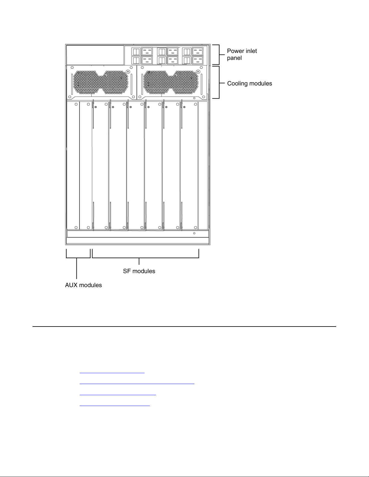
The front of the Virtual Services Platform 9000 chassis has ten slots for interface modules and
two slots for Control Processor (CP) modules. Slots are numbered from top to bottom. The
front of the Virtual Services Platform 9000 chassis also has two bays for cooling modules and
six bays for power supplies. The following figure shows the front view of the chassis.
Installation — Chassis October 2011 9
Page 10

9012 chassis installation fundamentals
Figure 1: Virtual Services Platform 9000 chassis front view
In the rear, the chassis has six slots for Switch Fabric (SF) modules and two auxiliary slots for
future use. Rear slots are numbered from right to left. The rear also has two bays for cooling
modules. There are six separate IEC 60320-C20 AC power inlets and six power switches which
connect the main AC power to their corresponding power supply bays. The following figure
shows the rear view of the chassis. The ground bonding location is located in the bottom right
part of the chassis.
10 Installation — Chassis October 2011
Comments? infodev@avaya.com
Page 11
Power supplies
Figure 2: Virtual Services Platform 9000 chassis rear view
Power supplies
This section describes the 9006 AC power supply, the power inlets and how to plan for feed
and power supply redundancy.
9006AC power supply on page 12
•
• Power supply and power inlet locations on page 12
• Power supply redundancy on page 12
Power feed redundancy on page 13
•
Installation — Chassis October 2011 11
Page 12

9012 chassis installation fundamentals
9006AC power supply
The Avaya Virtual Services Platform 9000 chassis has six bays for AC power supply
installation. Install the power supplies in the front of the chassis and plug the power plugs in
the corresponding power inlets at the back of the chassis.
To configure a Avaya Virtual Services Platform 9000 system, consider the total power
consumption to ensure proper system performance. The total input power consumption of the
components (modules and cooling modules) must not exceed the output power rating of the
power supply. For more information about the power consumption of each module, see
Component input power on page 42.
When the A vaya V irtual Services Platform 9000 operates in a redundant power configuration,
you can upgrade or replace power supplies while the chassis remains in operation.
For more information about power supply installation and electrical specifications, see Avaya
Virtual Services Platform 9000 Installation — AC Power Supply, NN46250-303.
Power supply and power inlet locations
In the front of the chassis, the power supply bays are numbered from left to right, so 1, 2, and
3 on the first row, and 4, 5, and 6 on the second row.
The power inlets in the back of chassis are numbered from left to right, so 3, 2, and 1 on the
first row, and 6, 5, and 4 on the second row (as viewed from the back).
For more information about grounding the Virtual Services Platform 9000 and related
precautions, see
Grounding the chassis on page 30.
Power supply redundancy
This section uses "n" to represent the number of power supplies required to operate the power
system without redundancy, and "m" to represent the number of redundant power supplies
required to improve the system availability. You can configure the Virtual Services Platform
9000 for n + n redundancy by means of distributing an "A" power feed to the "A" power shelf
(which comprises of AC power supplies 1, 2, and 3), and a "B" power feed to the "B" power
shelf (which comprises of AC power supplies 4, 5, and 6). Apply this power configuration
protection against simultaneous power supply and individual power feed failure. Use n + m
redundancy to ensure internal redundancy in the event of a power supply failure. Install an
additional power supply (additional to what you require to power your hardware configuration)
to provide n + m redundancy. If two separate power feeds are not available at the site power
distribution, you can only configure the system for n + m redundancy.
Use n + n redundancy to ensure redundancy in the event that an external failure occurs (for
example, an entire power feed within the building fails). To ensure n + n redundancy, you must
install power supplies to provide twice the power requirements of your hardware
configuration.
Important:
The system reserves the following power requirements:
• 80 Watts (W) each for the primary and secondary Control Processor (CP) modules
• 70 W each for the Switch Fabric (SF) modules located in slots 1 and 4
12 Installation — Chassis October 2011
Comments? infodev@avaya.com
Page 13

• 150 W each for the two IO fan trays
• 65 W each for the two SF fan trays
Cooling modules
Refer to
Component input power on page 42 for information on power consumption.
Power feed redundancy
Avaya recommends that you use two separate power feeds to plug the AC power supplies.
The power supplies in the 9012 chassis are divided in two shelves. The top shelf (shelf "A")
consists of power supplies 1, 2, and 3, while the bottom shelf (shelf "B") consists of power
supplies 4, 5, and 6. If you use n + n redundancy and plug the power supplies from the top
shelf in power feed "A", and the power supplies from the bottom shelf in power feed "B", this
gives you power feed redundancy. Each shelf can provide 3600 W or 6000 W, depending if
you use 100-120 V AC or 200-240 V AC. Ensure that each power supply connects to a
dedicated breaker.
Cooling modules
The Avaya Virtual Services Platform 9000 chassis uses four cooling modules. Two cooling
modules at the front of the chassis cool the CP and interface modules. Two cooling modules
at the back of the chassis cool the SF modules.
You install the cooling modules for the interface and CP modules at the front of the chassis.
The cooling modules plug into the midplane. The cooling air flows from left to right, as viewed
from the front. A green LED indicates correct fan operation.
You install the cooling modules for the SF modules at the back of the chassis. The cooling air
flows from front to back to cool the SF and auxiliary modules.
See Avaya Virtual Services Platform 9000 Installation — Cooling Modules, NN46250-302 for
information about installing cooling modules.
Switch Fabric module
With Release 3.1, you must install a minimum of three SF modules in the chassis. Avaya
recommends that you install a minimum of four SF modules for redundancy. You must install
an SF module in slots SF1 and SF4; install a third SF module in one of the remaining slots.
Each SF module connects to the ten different interface module slots and the two CP module
slots simultaneously. You can install a maximum of six SF modules in each chassis in a 5 + 1
redundancy configuration.
The SF module slot numbers increment from right to left when you view the chassis from the
rear. The slot location determines the module function. Slots 1 and 4 provide the arbitration
and scheduling for traffic (and therefore, bandwidth management) from the interface modules
Installation — Chassis October 2011 13
Page 14

9012 chassis installation fundamentals
and provide redundancy when both slots are populated. The other slots provide additional
bandwidth.
Important:
Avaya recommends that you install SF modules in both Slot 1 and Slot 4 (to provide
redundancy). Y ou must have a functioning SF module in at least one of those slots for proper
operation of the interface modules.
Bandwidth is dependent on your hardware configuration.
Control Processor module
The 9080CP module performs the following tasks:
• runs all high level protocols, for example Border Gateway Protocol (BGP) and Open
Shortest Path First (OSPF)
• distributes the routing update
• manages and configures the interface and SF modules
• maintains and monitors the health of the chassis
• displays the status of the modules installed at the back of the chassis using LEDs
Important:
Y ou need to ensure that the external Compact Flash card is installed in the CP module before
you power on the chassis or enable the CP module.
See Avaya Virtual Services Platform 9000 Installation — Modules, NN46250-301 for
information about installing CP modules.
Site requirements
Ensure that the installation site meets the space requirements described in this section. For
more information about environmental and electrical requirements, see Technical
specifications on page 41.
The installation site must provide sufficient free space around the chassis to ensure proper
ventilation and service access.
You can install up to three Avaya Virtual Services Platform 9000 chassis in a single rack.
Although there are no space requirement between units, leave enough room between units to
remove and replace modules.
14 Installation — Chassis October 2011
Comments? infodev@avaya.com
Page 15

Hardware requirements
Important:
Chassis units should be installed from the bottom up to ensure racks do not become top
heavy and fall over.
Plan ahead to have three people present to lift the chassis. The chassis weighs in excess of
160 lb (73 kg) and requires a minimum of three people to lift. A mechanical lift should always
be used when one is available.
Use the following guidelines to plan front and rear access:
• For proper ventilation, Avaya recommends 36 inches (in.) (91 centimeters [cm]) of free
space in both the front and the back of the machine, and also 6 in. (15.2 cm) on each
side.
• Air inlet temperature to each chassis must be within the specified range.
Important:
To ensure efficient cooling, both the air intake (left side of the chassis) and air exhaust (right
side of the chassis) require a minimum of 6 in. (152.4 mm) of distance from any adjacent
equipment which would either obstruct air flow or provide preheated air to the intake side.
Each power supply must operate from a dedicated branch circuit. For n + n redundancy, you
must connect half the branch circuits on one power feed, and the other half of the branch
circuits on a separate power feed. On top of power supply redundancy , this also provides power
feed redundancy.
Hardware requirements
This section includes information about the hardware shipped with the A vaya V irtual Services
Platform 9000 chassis.
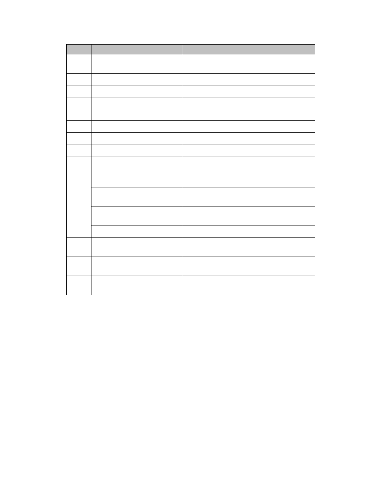
Shipped Assembly 9012 12 Slot Chassis hardware
In addition to the Avaya Virtual Services Platform 9000 chassis, your shipping container
contains several hardware accessories. Verify that the items in the shipping container match
those on the shipment packing list.
Use the following table as a checklist when you verify the contents of the shipping container.
Part numbers on page 39 for information about ordering replacement parts.
See
Table 1: 9012 chassis shipping accessories
Check
Accessory Usage
9012 chassis
Ten interface and Control
Processor (CP) filler panels
Installation — Chassis October 2011 15
Filler panels must be installed in unused slots.
Page 16
9012 chassis installation fundamentals
Check Accessory Usage
Four Switch Fabric (SF) filler
Filler panels must be installed in unused slots.
panels
Two Auxiliary card filler panels Filler panels must be installed in unused slots.
Regulatory label
Two SF fan trays
Two IO fan trays
One DB9 to DB9 connector
One accessory kit
One cable manager assembly
One generic label accessory kit
Screws and hardware: The hardware required to mount the chassis in
a rack depends on your rack type.
12 Phillips-head screws
12 clip nuts
4 Phillips-head screws
4 hex nuts
Mount the chassis to a rack rail.
Use the clip nuts, if necessary.
Mount the installation shelf to a rack rail.
Mount the installation shelf to a rack rail.
4 pan-head screws Install the cable management bracket.
Installation shelf Mount the Virtual Services Platform 9000
chassis in an equipment rack.
One left front cable
Manage network interface cables.
management bracket
Grounding kit hardware Connects the chassis to the ground of the
rack.
The following figure illustrates the accessories in the chassis shipping container.
16 Installation — Chassis October 2011
Comments? infodev@avaya.com
Page 17

Hardware requirements
Figure 3: Accessories of the chassis shipping container
Other equipment
You will require items not included in the Virtual Services Platform 9000 chassis accessory
package. The following sections describe these items. Before you install the Virtual Services
Platform 9000 hardware, ensure that you obtain all the cables, tools, and other equipment you
need.
To configure startup options and to monitor the results of startup diagnostics, you can attach
a PC, laptop, VT100 console or equivalent, such as a PC terminal emulator.
The hardware required to mount the Avaya Virtual Services Platform 9000 chassis in an
equipment rack depends on your equipment rack type.
You need a Phillips screwdriver to install the Virtual Services Platform 9000 chassis in a
standard rail-type equipment rack if using Avaya-supplied screws.
Install the device in standard EIA-310D 19-inch (in.) racks and ETSI 600-millimeter (mm) racks.
The chassis fits a standard 19-in. rack using the mounting brackets that ship with the unit. To
install the chassis in an ETSI 600-mm rack, you must provide mounting brackets to adapt the
chassis to the rack.
If the rack does not use threaded rail holes, you must use the supplied clip nuts with the clip
nut screws.
Avaya does not include the cables required for your network configuration in the Virtual
Services Platform 9000 chassis accessory package.
Installation — Chassis October 2011 17
Page 18
9012 chassis installation fundamentals
Successful installation verification
In a normal power-up sequence, the LEDs light as follows:
• After you apply power to the switch, the corresponding power supply AC power LEDs and
cooling module LED lights, and the Online LED for each interface module lights amber.
• Each interface module initiates a self-test during which the port and module LEDs display
various patterns to indicate the progress of the self-test.
• Upon successful completion of the self-test (within 5 to 15 minutes after you apply power,
depending on the module type), the interface module Online LED transitions from amber
to green.
If the LEDs on the modules light in this sequence, your installation is successful. Contact your
network administrator to verify that the Avaya Virtual Services Platform 9000 connects to the
network.
If the LEDs do not light in this sequence, contact your local Avaya Technical Solutions
Center.
Chassis installation time requirements
The following table lists the procedures you perform to install the Virtual Services Platform
9000 chassis and the estimated time you need to complete each procedure. Not all procedures
are required for every Virtual Services Platform 9000 system.
Table 2: Installation procedures and time requirements
Procedure Time requirement
Reducing the chassis weight 5 minutes
Attaching the mounting brackets 5 minutes
Mounting the chassis in a two-post rack 12–30 minutes
Installing the cable management brackets 5 minutes
Grounding the chassis 12 minutes
18 Installation — Chassis October 2011
Comments? infodev@avaya.com
Page 19

Chapter 4: 9012 chassis installation
About this task
This section describes how to install the Avaya Virtual Services Platform 9000 chassis.
Before you begin the installation of the Avaya Virtual Services Platform 9000 chassis, ensure you have
completed the following actions:
• Inspect all items for shipping damage. If you find items that are damaged, do not install the chassis.
Call the Avaya Technical Solutions Center in your area.
• Verify that the items in the shipping container match those on the shipment packing list.
• Verify that you have all other required hardware.
Warning:
The procedures in this task flow should be performed by trained service personnel only.
The following task flow shows you the sequence of procedures you perform to install the chassis. To link
to any procedure, select the procedure name in the list that follows the taskflow.
Installation — Chassis October 2011 19
Page 20

9012 chassis installation
Figure 4: 9012 chassis installation procedures
20 Installation — Chassis October 2011
Comments? infodev@avaya.com
Page 21

• Reduce the chassis weight on page 24
• Secure the chassis on page 27
• Assemble and install cable management brackets on page 28
Grounding the chassis on page 30
•
• Determining the minimum number of AC power supplies on page 35
Unpack the installation kit
Unpack the installation kit and remove the included equipment.
Unpack the installation kit
Note:
Extra screws and bolts are included to support a variety of installation options. You may not
need to use all of the hardware provided.
If the installation kit does not contain the above components, contact Avaya Support.
Installation — Chassis October 2011 21
Page 22

9012 chassis installation
Install the installation shelf
About this task
The installation shelf is an optional item used for installation of the chassis in a rack. You can
mount a chassis on top of another Virtual Services Platform 9000 chassis instead of using the
installation shelf.
Procedure
1. Use the rail guides provided at the top and bottom of the installation poster to identify
where you want the chassis bottom to rest, then mark that location and the location
of the rail guide holes on the front of the rack. Start at the bottom of the rack and
install subsequent chassis above it.
Note:
Folding or trimming off the margins of the poster will help with marking the
rack.
2. If the holes in the vertical supports require clip nuts, insert a clip nut in each of the
14 locations where you marked the holes. Clip nuts are included. If necessary , use
the clip nuts for your specific rack model.
22 Installation — Chassis October 2011
Comments? infodev@avaya.com
Page 23

Install the installation shelf
3. Place the installation shelf at the mark on the rack, inside the rails. Hold the
installation shelf in position, and then align the mounting rail with the two holes on
each side of the vertical rack support.
4. Insert a Phillips screw through each installation shelf mounting hole and into the
corresponding hole in the rack.
5. If using hex nuts, add a nut to each screw and tighten using a hex wrench.
6. Tighten each screw with a Phillips screwdriver.
Installation — Chassis October 2011 23
Page 24

9012 chassis installation
Reduce the chassis weight
About this task
Reduce the chassis weight to make the chassis easier to lift and to reduce the risk of personal
injury or equipment damage.
Procedure
1. Remove the 10 I/O filler modules from the front of the chassis.
2. Remove the 2 cooling modules from the front of the chassis.
24 Installation — Chassis October 2011
Comments? infodev@avaya.com
Page 25

Reduce the chassis weight
3. Unseat the I/O filler module by loosening the 2 captive screws, grasping the two
handles, and gently pulling the module out and away from the chassis.
4. Remove the cooling modules by pulling the retaining pin that holds it in place while
gently pulling the module’s handle to move it out and away from the chassis.
Installation — Chassis October 2011 25
Page 26

9012 chassis installation
Do not install additional components before mounting the chassis in the rack.
All unused slots should contain filler modules. Ensure filler modules removed to
reduce the chassis weight are reinstalled after chassis installation.
Lift the chassis
About this task
The chassis weighs in excess of 160 lb (73 kg) and requires a minimum of three people to lift.
Always use a mechanical lift when one is available.
Important:
Important:
26 Installation — Chassis October 2011
Comments? infodev@avaya.com
Page 27

Secure the chassis
Use the recessed handles at the top and bottom of the chassis sides to lift the chassis. From
the rear: Lift the chassis from the bottom only.
Important:
Reduce the weight of the chassis as much as possible before you lift it. Always use a
mechanical lift when one is available. Ensure you have at least three people to lift the
chassis. Use a third person to support the chassis from behind the rack, as you position the
chassis on the shelf and hold it in place. Take care to lift the chassis from the bottom.
Secure the chassis
About this task
Mount the Avaya Virtual Services Platform 9000 chassis in a standard two-post or four-post
equipment rack.
Procedure
1. Hold the Virtual Services Platform 9000 chassis in position and align the flanged
end of the chassis mounting bracket with the holes on either side of the vertical rack
support.
2. Ensure that the 7 hole pairs on either side of the rack vertical supports match
horizontally.
3. Insert 4 phillips screws through each hole on the mounting bracket in the 7 screw
positions in the flange and rack. If you‘ll be installing the optional I/O cable bracket
Installation — Chassis October 2011 27
Page 28

9012 chassis installation
4. Tighten each screw with a Phillips screwdriver.
then don’t insert screws into the top (1st), middle (4th) and bottom (7th) screw
positions of the left side flange and rack.
Assemble and install cable management brackets
About this task
This procedure is used to install the I/O and power cable brackets. Use these brackets to keep
cable clusters fastened and out of the way but still accessible for maintenance.
Important:
Do not attach any cables until after the bracket installation.
Procedure
1. Attach the three Z brackets to the vertical cable bracket as shown below using 6 of
the screws provided. Nuts are not required since the Z brackets are already
threaded on one side for connection to the I/O cable bracket using screws alone.
28 Installation — Chassis October 2011
Comments? infodev@avaya.com
Page 29

Assemble and install cable management brackets
2. Use 3 Phillips screws to fasten the I/O cable management assembly to the top,
middle and bottom screw positions of the left flange and rail.
3. Remove the two upper screws from the power cable receptacle panel on the rear
of the chassis.
4. Position the power cable bracket notches over the chassis positioning studs and
reuse the two screws you removed to fasten the power cable bracket as shown. Do
not attach any cables until after the bracket installation.
Installation — Chassis October 2011 29
Page 30

9012 chassis installation
Grounding the chassis
Before you begin
• Ensure you have a two-hole cable lug that fits over the grounding studs.
• Ensure you have a nut and a locking washer for the grounding stud.
• Ensure you have a 6-AWG green and yellow grounding wire long enough to connect to
the ground point.
• Ensure you have a 6 mm socket or nut driver.
About this task
Avaya recommends that you ground the A vaya V irtual Services Platform 9000 chassis before
you install power supplies or connect power and network cables to the system.
Procedure
1. Crimp the two hole lug onto the ground wire.
2. Attach the chassis ground cable to the grounding studs on the chassis. As shown
in the following figure, the studs are located on the bottom right part of the back of
the chassis.
30 Installation — Chassis October 2011
Comments? infodev@avaya.com
Page 31

Grounding the chassis
Job aid
3. Bond the chassis ground cable to the single point ground window.
The following figure shows an example of how to attach the chassis ground cable to the rack
grounding strip.
Installation — Chassis October 2011 31
Page 32

9012 chassis installation
Figure 5: Rack grounding strip example
32 Installation — Chassis October 2011
Comments? infodev@avaya.com
Page 33

Grounding the chassis
The following figure shows the ESD ground strap input location on the front of the chassis.
There are also two ESD ground strap input sites on the rear of the chassis.
Installation — Chassis October 2011 33
Page 34

9012 chassis installation
34 Installation — Chassis October 2011
Comments? infodev@avaya.com
Page 35

Chapter 5: Chassis operations
About this task
This section describes some of the routine tasks you perform to operate the Avaya Virtual Services
Platform 9000.
Determining the minimum number of AC power supplies on page 35
•
• Powering up the system on page 36
• Resetting the Avaya Virtual Services Platform 9000 on page 37
Determining the minimum number of AC power supplies
Before you begin
For more information about the power requirements for each module, see Component input
power on page 42.
Important:
The system reserves the following power requirements:
• 80 Watts (W) each for the primary and secondary Control Processor (CP) modules
• 70 W each for the Switch Fabric (SF) modules located in slots 1 and 4
• 150 W each for the two IO fan trays
• 65 W each for the two SF fan trays
•
About this task
Determine the minimum number of power supplies required to ensure there is enough power
to operate the installed components. You can install a maximum of six 9006AC power
supplies.
Procedure
1. Add the total input power consumption for all components (modules and cooling
modules assemblies).
2. Refer to the output power rating of the power supply based on the input
connection.
Installation — Chassis October 2011 35
Page 36

Chassis operations
Important:
If either the individual or the combined power requirements for the components
exceed the power supply rating, you need to add at least one additional power
supply to your configuration.
3. Consider your redundant power supply needs.
Powering up the system
Before you begin
• For more information about installing a 9006AC power supply , see Avaya Virtual Services
Platform 9000 Installation — Power Supply, NN46250-303.
• For more information about the power supply LEDs, see Avaya Virtual Services Platform
9000 Installation — Power Supply, NN46250-303.
Caution:
The AC power switches are double pole. The 9006AC power supply incorporates double
pole and neutral fusing.
About this task
Connect the power supplies and power up the system to start up the Avaya Virtual Services
Platform 9000.
Procedure
1. Determine power subsystem operating configuration based on module load
requirements and power redundancy needs.
2. Install the required power supplies in the power shelf bays.
3. Ensure the AC power switches are in the off position.
4. Determine the appropriate power cord based on the power supply operating power
and site requirements.
5. Connect the AC power cords to the AC power inlets and the power outlets.
6. For each power supply, turn on the corresponding power switch to the on
position.
If your chassis contains multiple power supplies, you can turn on the power supplies
simultaneously or one at a time. If you wait too long to turn on the additional power
supplies, one or more of the power supplies could stay or enter current limit based
on the system load condition until you power on a sufficient number of power
supplies to guarantee the system powers on.
36 Installation — Chassis October 2011
Comments? infodev@avaya.com
Page 37

Resetting the Avaya Virtual Services Platform 9000
7. Verify the AC power LEDs on each power supply illuminates green, and that the
service and fault LEDs are not illuminated.
8. Verify the cooling module LED on the CP modules illuminate green.
9. Verify that air flows from the cooling modules out through the vents of the chassis,
and that the power supply fans are operational.
The cooling module LED can illuminate red while the fans power to operational
speed.
10. If the power supply AC LEDs remain off indicating loss of AC power, the service or
fault LEDs are illuminated and you cannot feel air flow from the chassis vents, or
from each power supply, turn the power switch to the off position to diagnose the
problem or replace the failed power supply.
If the problem persists, contact the Avaya Technical Solutions Center.
Resetting the Avaya Virtual Services Platform 9000
About this task
Reset the Avaya Virtual Services Platform 9000 to restart the hardware without cycling
power.
Procedure
On the CP module, press Reset.
The following figure shows the location of the recessed Reset button.
Installation — Chassis October 2011 37
Page 38

Chassis operations
38 Installation — Chassis October 2011
Comments? infodev@avaya.com
Page 39

Chapter 6: Part numbers
The following table lists the Avaya Virtual Services Platform 9000 part numbers associated with the
hardware.
Products can be ordered with European Union Environmental Directive (EUED) Restriction of Hazardous
Substances (RoHS) (EUED RoHS) compliancy. EUED RoHS compliant products are designated with E5 or -E6 (for example EC1405A01-E6).
Table 3: Part numbers
Part number Item
EC1402001-E6 Shipped Assembly 9012 12 Slot Chassis
EC1405A01-E6 9006AC Power Supply
EC1404007-E6 9080CP CPU Module
EC1404001-E6 9024XL 24 SFP+ Module
EC1404002-E6 9048GB 48 SFP Module
EC1404003-E6 9048GT 48 10/100/1000 Module
EC1411001-E6 9012SC Side Fan Tray
EC1411002-E6 9012FC Fabric Fan Tray
EC1404006-E6 9090SF Switch fabric module
EC1411006-E6 Spare Front Module Filler Panel for 9012 12-Slot Chassis
EC1411007-E6 Spare Switch Fabric Filler Panel for 9012 12-Slot Chassis
EC1411008-E6 Spare Power Supply Filler Panel for 9012 12-Slot Chassis
EC1411009-E6 Spare Auxiliary Module Filler Panel for 9012 12-Slot Chassis
EC1411010-E6 2GB Compact Flash Memory Card for 9080CP Module
Installation — Chassis October 2011 39
Page 40

Part numbers
40 Installation — Chassis October 2011
Comments? infodev@avaya.com
Page 41

Chapter 7: Technical specifications
This section details the specifications for the Avaya Virtual Services Platform 9000.
• Chassis weight on page 41
• AC power supply on page 41
Component input power on page 42
•
• Power supply selection on page 43
• Virtual Services Platform 9000 chassis specifications on page 44
Chassis weight
The following table provides the chassis weight with each component.
Table 4: Chassis weight including components and cables
Chassis and components
Chassis and midplane 160 lb (73 kg)
Chassis, midplane, and cooling modules 183 lb (83 kg)
Chassis midplane, cooling modules, and full
length filler modules
AC power supply
This section provides power ratings for the AC power supply.
The following table lists the input power specifications.
Table 5: AC input power specifications
Parameter
Input current 13.3 A (100 V AC) - 11.2 A
288 lb (131 kg)
Specification at input
voltage 100-120 V AC
(120 V AC)
Weight
Specification at input
voltage 200-240 V AC
11.8 A (200 V AC) – 9.9 A
(240 V AC)
Operating frequency range 47–63 Hz 47-63 Hz
Installation — Chassis October 2011 41
Page 42

Technical specifications
Parameter Specification at input
voltage 100-120 V AC
Input volt-ampere (VA) 1445 VA 2325 VA
Efficiency 85% minimum, 90% typical 88% minimum, 93% typical
Input power consumption 1416 W 2277 W
Heat dissipation (thermal
output)
Hold-up time (See note 1.) 25 ms 20 ms
Note 1: Measurementstarts at zero crossing of the AC voltage. Measurement made at
fullload and voltage is allowed to decay to 44 VDC.
724 British Thermal Unit
(BTU)/hour
Specification at input
voltage 200-240 V AC
933 BTU/hour
The following table lists the DC output power specifications.
Table 6: DC output power specifications
Parameter Specification at input voltage
100–120 V AC
Maximum main output power 1200 W 2000 W
Maximum main output current 22 A 37 A
Specification at
input voltage 200–
240 V AC
Auxiliary output voltage / power 5 V DC / 3.75 W 5 V DC / 3.75 W
Output voltage set-point 54 V DC 54 V DC
Mean time between failures (See
note 1.)
Note 1:Per telcordia SR-332, 25 C, full load, method 1, case III
Component input power
The following table provides input power specifications for the Virtual Services Platform 9000
components.
Important:
The system reserves the following power requirements:
• 80 Watts (W) each for the primary and secondary Control Processor (CP) modules
• 70 W each for the Switch Fabric (SF) modules located in slots 1 and 4
• 150 W each for the two IO fan trays
400 000 hours 400 000 hours
42 Installation — Chassis October 2011
Comments? infodev@avaya.com
Page 43

• 65 W each for the two SF fan trays
•
Table 7: Component input power
Component Total input power (watts) Thermal output rating (BTU/
Rack mount
hour)
9080CP Central
Processor Module
9090SF Switch Fabric
Module, slots 1 and 4.
9090SF Switch Fabric
Module, slots 2, 3, 5, and
6.
9012FC Fabric Fan Tray
(Maximum fan speed)
9012SC Side Fan Tray
(Maximum fan speed)
9048GT interface module 350 1194
9048GB interface module 340 1160
9024XL interface module 575 1962
Rack mount
80 273
70 239
50 170
65 222
150 512
Y ou can install a maximum of three Avaya Virtual Services Platform 9000 chassis in a standard
19 in. wide 7 ft. tall rack.
Important:
Chassis units should be installed from the bottom up to ensure racks do not become top
heavy and fall over.
Power supply selection
Power management identifies the available power in the chassis, called the power budget, and
determines if enough power is available to operate the installed components. For more
information about the power management feature and configuration instructions, see Avaya
Virtual Services Platform 9000 Administration, NN46250-600
Installation — Chassis October 2011 43
Page 44

Technical specifications
Virtual Services Platform 9000 chassis specifications
This section provides physical, environmental, and electrical specifications for the Avaya
Virtual Services Platform 9000 chassis and includes the following topics:
Physical specifications on page 44
•
• Network Equipment Building Standard on page 44
Environmental specifications on page 44
•
• Maximum airflow on page 45
International regulatory requirements on page 45
•
Physical specifications
The following physical specifications apply to the Avaya Virtual Services Platform 9000
chassis.
Table 8: 9012 chassis physical specifications
Parameter Specification
Height 24.375 in. (61.91 cm)
Rack units (RU) 14
Width 17.5 in. (44.45 cm)
Depth 32.5 in. (82.55 cm) plus cable
management system
Weight Chassis and midplane 160 lb (73 kg)
Chassis and midplane, and cooling
modules
Chassis and midplane, cooling modules,
and full length filler modules
183 lb (83 kg)
288 lb (131 kg)
Network Equipment Building Standard
The Virtual Services Platform 9000 chassis does not comply with Network Equipment Building
Standard (NEBS) Level 3 as specified in SR3580.
Environmental specifications
The following environmental specifications apply to the Virtual Services Platform 9000
chassis.
44 Installation — Chassis October 2011
Comments? infodev@avaya.com
Page 45

Virtual Services Platform 9000 chassis specifications
Table 9: 9012 chassis environmental specifications
Parameter Specification
Operating temperature 0C to 40C (32F to 104F)
Storage temperature – 25C to 70C (– 13F to 158F)
Operating humidity 10% to 90%
Storage humidity 0 to 90%
Operating altitude 0 ft to 10 000 ft
Storage altitude 0 ft to 10 000 ft
Maximum airflow
The maximum airflow specification for the Virtual Services Platform 9000 chassis is 500
linear ft/min for side-to-side airflow in the front of the chassis, and 350 linear ft/min for front-toback airflow for modules installed at the rear of the chassis.
International regulatory requirements
The Virtual Services Platform 9000 chassis conforms to the following international regulatory
requirements:
Electromagnetic emissions on page 45
•
Electromagnetic immunity on page 45
•
• Safety agency certification on page 46
Electromagnetic emissions
The Virtual Services Platform 9000 chassis conforms to the following electromagnetic
emissions standards.
Table 10: 9012 chassis electromagnetic emissions
Parameter
United States FCC CFR47 Part 15, Subpart B, Class A
Canada ICES-003, Issue-4, Class A
Europe EN 55022:2006/ A1:2007 Class A; EN
61000-3-2/A14, EN 300 386 v1.3.3,
EN55024:1998/A1:2001/A2:2003, EN
61000-3-3:1995:A1:2001/A2:2005
Australia/New Zealand AS/NZS CISPR 22:2006, Class A
Japan VCCI-V3/97.04, Class A
Specification
Electromagnetic immunity
The Virtual Services Platform 9000 chassis conforms to the following electromagnetic immunity
standards.
Installation — Chassis October 2011 45
Page 46

Technical specifications
Table 11: 9012 chassis electromagnetic immunity
Global basis for certification CISPR 24:1997
Europe EN 55024:1998
Safety agency certification
The Virtual Services Platform 9000 chassis conforms to the following safety agency
standards.
Table 12: 9012 chassis safety agency certification
Global basis for certification IEC 60950-1 current edition with all CB member
US ULIEC 60950-1
Canada CSA 22.2 No. IEC 60950-1
Parameter Specification
Parameter Specification
deviations
Europe ENIEC 60950-1 (CE Marking)
Australia/New Zealand AS/NZS IEC 60950-1
46 Installation — Chassis October 2011
Comments? infodev@avaya.com
Page 47

Chapter 8: Regulatory Information and
Safety Precautions
Read the information in this section to learn about regulatory conformities and compliances.
International Regulatory Statements of Conformity
This is to certify that the Avaya Virtual Services Platform 9000 chassis and components
installed within the chassis were evaluated to the international regulatory standards for
electromagnetic compliance (EMC) and safety and were found to have met the requirements
for the following international standards:
• EMC—Electromagnetic Emissions—CISPR 22, Class A
• EMC—Electromagnetic Immunity—CISPR 24
• Electrical Safety—IEC 60950, with CB member national deviations
Further, the equipment has been certified as compliant with the national standards as detailed
in the following sections.
National Electromagnetic Compliance (EMC) Statements of Compliance
FCC Statement (USA only)
This equipment has been tested and found to comply with the limits for a Class A digital device,
pursuant to Part 15 of the Federal Communications Commission (FCC) rules. These limits are
designed to provide reasonable protection against harmful interference when the equipment
is operated in a commercial environment. This equipment generates, uses, and can radiate
radio frequency energy . If it is not installed and used in accordance with the instruction manual,
it may cause harmful interference to radio communications. Operation of this equipment in a
residential area is likely to cause harmful interference, in which case users will be required to
take whatever measures may be necessary to correct the interference at their own expense.
Installation — Chassis October 2011 47
Page 48

Regulatory Information and Safety Precautions
ICES Statement (Canada only)
Canadian Department of Communications Radio Interference Regulations
This digital apparatus (Virtual Services Platform 9000 chassis and installed components) does
not exceed the Class A limits for radio-noise emissions from digital apparatus as set out in the
Radio Interference Regulations of the Canadian Department of Communications.
Règlement sur le brouillage radioélectrique du ministère des Communications
Cet appareil numérique (Virtual Services Platform 9000 chassis) respecte les limites de bruits
radioélectriques visant les appareils numériques de classe A prescrites dans le Règlement sur
le brouillage radioélectrique du ministère des Communications du Canada.
CE Marking Statement (Europe only)
EN 55 022 Statements
This is to certify that the Virtual Services Platform 9000 chassis and components installed
within the chassis are shielded against the generation of radio interference in accordance with
the application of Council Directive 2004/108/EC. Conformity is declared by the application of
EN 55 022 Class A (CISPR 22).
Caution:
This device is a Class A product. Operation of this equipment in a residential area is likely
to cause harmful interference, in which case users are required to take appropriate
measures necessary to correct the interference at their own expense.
EN 55 024 Statement
This is to certify that the Virtual Services Platform 9000 chassis is shielded against the
susceptibility to radio interference in accordance with the application of Council Directive
2004/108/EC. Conformity is declared by the application of EN 55 024 (CISPR 24).
EN 300386 Statement
The Virtual Services Platform 9000 chassis complies with the requirements of EN 300386
V1.3.3 for emissions and for immunity for a Class A device intended for use in either
Telecommunications centre or locations other than telecommunications centres given the
performance criteria as specified by the manufacturer.
EC Declaration of Conformity
This product conforms to the provisions of the R&TTE Directive 1999/5/EC.
European Union and European Free Trade Association (EFTA) Notice
All products labeled with the CE marking comply with R&TTE Directive (1999/5/
EEC) which includes the Electromagnetic Compliance (EMC) Directive
(2004/108/EC) and the Low Voltage Directive (2006/95/EC) issued by the
Commission of the European Community.
48 Installation — Chassis October 2011
Comments? infodev@avaya.com
Page 49

National Safety Statements of Compliance
Compliance with these directives implies conformity to the following European Norms (ENs).
The equivalent international standards are listed in parenthesis.
• EN 55022 (CISPR 22)–Electromagnetic Interference
• EN 55024 (IEC 61000-4-2, -3, -4, -5, -6, -8, -11)–Electromagnetic Immunity
• EN 61000-3-2 (IEC 610000-3-2)–Power Line Harmonics
• EN 61000-3-3 (IEC 610000-3-3)–Power Line Flicker
VCCI Statement (Japan/Nippon only)
This is a Class A product based on the standard of the Voluntary Control Council for
Interference (VCCI) for information technology equipment. If this equipment is used in a
domestic environment, radio disturbance may arise. When such trouble occurs, the user may
be required to take corrective actions.
National Safety Statements of Compliance
CE Marking Statement (Europe only)
EN 60 950 Statement
This is to certify that the Virtual Services Platform 9000 chassis and components installed
within the chassis are in compliance with the requirements of EN 60 950 in accordance with
the Low Voltage Directive. Additional national differences for all European Union countries
have been evaluated for compliance. Some components installed within the Virtual Services
Platform 9000 chassis may use a nickel-metal hydride (NiMH) and/or lithium-ion battery. The
NiMH and lithium-ion batteries are long-life batteries, and it is very possible that you will never
need to replace them. However, should you need to replace them, refer to the individual
component manual for directions on replacement and disposal of the battery.
Installation — Chassis October 2011 49
Page 50

Regulatory Information and Safety Precautions
Denan Statement (Japan/Nippon only)
Safety Messages
This section describes the different precautionary notices used in this document. This section
also contains precautionary notices that you must read for safe operation of the A vaya V irtual
Services Platform 9000.
Notices
Notice paragraphs alert you about issues that require your attention. The following sections
describe the types of notices. For a list of safety messages used in this guide and their
translations, see the Translations of safety messages chapter.
Attention Notice
Important:
An attention notice provides important information regarding the installation and operation
of Avaya products.
Caution ESD Notice
Electrostatic alert:
ESD
ESD notices provide information about how to avoid discharge of static electricity and
subsequent damage to Avaya products.
Electrostatic alert:
ESD (décharge électrostatique)
La mention ESD fournit des informations sur les moyens de prévenir une décharge
électrostatique et d'éviter d'endommager les produits Avaya.
50 Installation — Chassis October 2011
Comments? infodev@avaya.com
Page 51

Safety Messages
Electrostatic alert:
ACHTUNG ESD
ESD-Hinweise bieten Information dazu, wie man die Entladung von statischer Elektrizität
und Folgeschäden an Avaya-Produkten verhindert.
Electrostatic alert:
PRECAUCIÓN ESD (Descarga electrostática)
El aviso de ESD brinda información acerca de cómo evitar una descarga de electricidad
estática y el daño posterior a los productos Avaya.
Electrostatic alert:
CUIDADO ESD
Os avisos do ESD oferecem informações sobre como evitar descarga de eletricidade
estática e os conseqüentes danos aos produtos da Avaya.
Electrostatic alert:
ATTENZIONE ESD
Le indicazioni ESD forniscono informazioni per evitare scariche di elettricità statica e i danni
correlati per i prodotti Avaya.
Caution Notice
Caution:
Caution notices provide information about how to avoid possible service disruption or
damage to Avaya products.
Caution:
ATTENTION
La mention Attention fournit des informations sur les moyens de prévenir une perturbation
possible du service et d'éviter d'endommager les produits Avaya.
Caution:
ACHTUNG
Achtungshinweise bieten Informationen dazu, wie man mögliche Dienstunterbrechungen
oder Schäden an Avaya-Produkten verhindert.
Caution:
PRECAUCIÓN
Los avisos de Precaución brindan información acerca de cómo evitar posibles
interrupciones del servicio o el daño a los productos Avaya.
Installation — Chassis October 2011 51
Page 52

Regulatory Information and Safety Precautions
Caution:
CUIDADO
Os avisos de cuidado oferecem informações sobre como evitar possíveis interrupções do
serviço ou danos aos produtos da Avaya.
Caution:
ATTENZIONE
Le indicazioni di attenzione forniscono informazioni per evitare possibili interruzioni del
servizio o danni ai prodotti Avaya.
Warning Notice
Warning:
Warning notices provide information about how to avoid personal injury when working with
Avaya products.
Warning:
AVERTISSEMENT
La mention Avertissement fournit des informations sur les moyens de prévenir les risques
de blessure lors de la manipulation de produits Avaya.
Warning:
WARNUNG
Warnhinweise bieten Informationen dazu, wie man Personenschäden bei der Arbeit mit
Avaya-Produkten verhindert.
Warning:
ADVERTENCIA
Los avisos de Advertencia brindan información acerca de cómo prevenir las lesiones a
personas al trabajar con productos Avaya.
Warning:
AVISO
Os avisos oferecem informações sobre como evitar ferimentos ao trabalhar com os produtos
da Avaya.
Warning:
AVVISO
Le indicazioni di avviso forniscono informazioni per evitare danni alle persone durante
l'utilizzo dei prodotti Avaya.
52 Installation — Chassis October 2011
Comments? infodev@avaya.com
Page 53

Safety Messages
Danger High Voltage Notice
Voltage:
Danger—High Voltage notices provide information about how to avoid a situation or
condition that can cause serious personal injury or death from high voltage or electric
shock.
Voltage:
La mention Danger—Tension élevée fournit des informations sur les moyens de prévenir
une situation ou une condition qui pourrait entraîner un risque de blessure grave ou mortelle
à la suite d'une tension élevée ou d'un choc électrique.
Voltage:
GEFAHR
Hinweise mit „Vorsicht – Hochspannung“ bieten Informationen dazu, wie man Situationen
oder Umstände verhindert, die zu schweren Personenschäden oder Tod durch
Hochspannung oder Stromschlag führen können.
Voltage:
PELIGRO
Los avisos de Peligro-Alto voltaje brindan información acerca de cómo evitar una situación
o condición que cause graves lesiones a personas o la muerte, a causa de una electrocución
o de una descarga de alto voltaje.
Voltage:
PERIGO
Avisos de Perigo—Alta Tensão oferecem informações sobre como evitar uma situação ou
condição que possa causar graves ferimentos ou morte devido a alta tensão ou choques
elétricos.
Voltage:
PERICOLO
Le indicazioni Pericolo—Alta tensione forniscono informazioni per evitare situazioni o
condizioni che potrebbero causare gravi danni alle persone o il decesso a causa dell'alta
tensione o di scosse elettriche.
Danger Notice
Danger:
Danger notices provide information about how to avoid a situation or condition that can
cause serious personal injury or death.
Installation — Chassis October 2011 53
Page 54

Regulatory Information and Safety Precautions
Danger:
La mention Danger fournit des informations sur les moyens de prévenir une situation ou une
condition qui pourrait entraîner un risque de blessure grave ou mortelle.
Danger:
GEFAHR
Gefahrenhinweise stellen Informationen darüber bereit, wie man Situationen oder
Umständen verhindert, die zu schweren Personenschäden oder Tod führen können.
Danger:
PELIGRO
Los avisos de Peligro brindan información acerca de cómo evitar una situación o condición
que pueda causar lesiones personales graves o la muerte.
Danger:
PERIGO
Avisos de perigo oferecem informações sobre como evitar uma situação ou condição que
possa causar graves ferimentos ou morte.
Danger:
PERICOLO
Le indicazioni di pericolo forniscono informazioni per evitare situazioni o condizioni che
potrebbero causare gravi danni alle persone o il decesso.
54 Installation — Chassis October 2011
Comments? infodev@avaya.com
Page 55

Chapter 9: T ranslations of safety messages
This section contains translations of precautionary notices that you must read and follow for safe operation
of the Avaya Virtual Services Platform 9000.
Class A device caution statement
Caution:
This device is a Class A product. Operation of this equipment in a residential area is likely to cause
harmful interference, in which case users are required to take appropriate measures necessary to
correct the interference at their own expense.
Caution:
ATTENTION
Le périphérique est un produit de Classe A. Le fonctionnement de cet équipement dans une zone
résidentielle risque de causer des interférences nuisibles, auquel cas l'utilisateur devra y remédier à
ses propres frais.
Caution:
ACHTUNG
Dies ist ein Gerät der Klasse A. Bei Einsatz des Geräts in W ohngebieten kann es Störungen des Radiound Fernsehempfangs verursachen. In diesem Fall muss der Benutzer alle notwendigen Maßnahmen
ergreifen, die möglicherweise nötig sind, um die Störungen auf eigene Rechnung zu beheben.
Caution:
PRECAUCIÓN
Este es un producto clase A. El uso de este equipo en áreas residenciales puede causar interferencias
nocivas, en cuyo caso, se requerirá que los usuarios tomen cualquier medida necesaria para corregir
la interferencia por cuenta propia.
Caution:
CUIDADO
Este dispositivo é um produto Classe A. Operar este equipamento em uma área residencial
provavelmente causará interferência prejudicial; neste caso, espera-se que os usuários tomem as
medidas necessárias para corrigir a interferência por sua própria conta.
Caution:
ATTENZIONE
Installation — Chassis October 2011 55
Page 56

Translations of safety messages
Questo dispositivo è un prodotto di Classe A. Il funzionamento di questo apparecchio in aree
residenziali potrebbe causare interferenze dannose, nel cui caso agli utenti verrà richiesto di adottare
tutte le misure necessarie per porre rimedio alle interferenze a proprie spese.
Electrostatic discharge caution statement
Electrostatic alert:
ESD
To prevent damage from electrostatic discharge, always wear an antistatic wrist strap connected to an
electrostatic discharge (ESD) jack when performing maintenance on this product. Ensure that the wrist
strap makes contact with your skin.
Electrostatic alert:
ATTENTION ESD (décharge électrostatique)
Pour prévenir tout dommage dû à une décharge électrostatique, vous devez toujours porter un un
bracelet antistatique connecté à une prise pour décharge électrostatique (ESD) lors de l'exécution
d'opérations de maintenance sur ce produit. Assurez-vous que le bracelet antistatique est en contact
avec votre peau.
Electrostatic alert:
ACHTUNG ESD
Um Schäden durch elektrostatische Entladung zu verhindern, tragen Sie bei der Instandhaltung dieses
Produkts immer ein antistatisches Band am Handgelenk, das mit einer ESD-Buchse verbunden ist.
Stellen Sie sicher, dass das Band am Handgelenk Kontakt zur Haut hat.
Electrostatic alert:
PRECAUCIÓN ESD (Descarga electrostática)
Para prevenir el daño producido por una descarga electrostática, use siempre una pulsera antiestática
conectada a un enchufe de descarga electrostática (ESD) al realizar el mantenimiento de este
producto. Asegúrese de que la pulsera antiestática haga contacto con su piel.
Electrostatic alert:
CUIDADO ESD
Para evitar danos com descarga eletrostática, sempre use uma pulseira antiestática que esteja
conectada a uma tomada de descarga eletrostática (ESD) quando estiver realizando a manutenção
deste produto. Certifique-se de que a pulseira esteja em contato com sua pele.
Electrostatic alert:
ATTENZIONE ESD
Per evitare danni derivanti da scariche elettrostatiche, indossare sempre un polsino antistatico collegato
a una presa di scarico elettrostatico (ESD) durante la manutenzione del prodotto. Accertarsi che il
polsino sia a contatto con la pelle.
56 Installation — Chassis October 2011
Comments? infodev@avaya.com
Page 57

Laser fiber optic warning statement
Warning:
Risk of eye injury by laser
Fiber optic equipment can emit laser or infrared light that can injure your eyes. Never look into an optical
fiber or connector port. Always assume that fiber optic cables are connected to a light source.
Warning:
AVERTISSEMENT
Risques de blessure oculaire par lumière laser
L'équipement de fibres optiques peut émettre une lumière laser ou infrarouge nuisible à vos yeux. Ne
regardez jamais en direction de fibres optiques ou d'un port connecteur. Supposez toujours que les
câbles de fibres optiques sont connectés à une source de lumière.
Warning:
WARNUNG
Risiko einer Augenverletzung durch Laser
Glasfasergeräte können Laserstrahlen oder ultraviolettes Licht aussenden, das Ihre Augen verletzen
kann. Schauen Sie nie direkt in einen Glasfaserleiter oder Verbindungsanschluss. Gehen Sie immer
davon aus, dass Glasfaserkabel mit einer Lichtquelle verbunden sind.
Warning:
ADVERTENCIA
Riesgo de lesión en los ojos por láser
El equipo de fibra óptica puede emitir una luz láser o infrarroja que dañe sus ojos. Nunca mire un puerto
de fibra óptica o conector. Siempre asuma que los cables de fibra óptica están conectados a una fuente
de luz.
Warning:
AVISO
O laser pode causar ferimentos no olho
O equipamento de fibra ótica pode emitir laser ou luz infravermelha que pode causar danos a sua vista.
Nunca olhe para dentro da fibra ótica ou da porta do conector. Tenha sempre em mente que os cabos
de fibra ótica estão ligados a uma fonte de luz.
Warning:
AVVISO
Rischio di ustioni agli occhi dovute al laser
Installation — Chassis October 2011 57
Page 58

Translations of safety messages
Le apparecchiature con fibre ottiche possono emettere raggi laser o infrarossi in grado di provocare
ferite agli occhi. Non guardare mai all'interno di una porta di connessione o una fibra ottica. Tenere
sempre presente che i cavi a fibra ottica sono collegati a una sorgente luminosa.
Lifting 9012 chassis warning statement
Warning:
Risk of personal injury
It requires three people to lift the Virtual Services Platform 9000 chassis. To make the chassis lighter,
remove the modules and power supplies before you lift it.
Warning:
AVERTISSEMENT
Risques de blessure corporelle
Trois personnes sont nécessaires pour soulever le châssis VSP. Pour alléger le châssis, retirez les
modules et les alimentations avant de le soulever.
Warning:
WARNUNG
Verletzungsrisiko
Es sind 3 Personen notwendig, um das Chassis des VSP anzuheben. Entfernen Sie vor dem Anheben
die Module und die Netzteile, um so das Gewicht des Chassis zu reduzieren.
Warning:
ADVERTENCIA
Riesgo de lesiones
Se necesitan tres personas para levantar el chasis de VSP. Para alivianar el peso, retire los módulos
y las fuentes de alimentación antes de levantarlo.
Warning:
AVISO
Risco de ferimento
Para erguer o chassi VSP, são necessárias três pessoas. Para erguer o chassi, remova os módulos e
as fontes de alimentação antes de erguê-lo.
Warning:
AVVISO
Rischio di lesioni personali
Per sollevare lo chassis VSP, sono necessarie tre persone. Per alleggerire lo chassis, rimuovere i
moduli e gli alimentatori prima di sollevarlo.
58 Installation — Chassis October 2011
Comments? infodev@avaya.com
Page 59

Chapter 10: Customer service
Visit the Avaya Web site to access the complete range of services and support that Avaya provides. Go
to www.avaya.com or go to one of the pages listed in the following sections.
Navigation
• Getting technical documentation on page 59
• Getting product training on page 59
• Getting help from a distributor or reseller on page 59
Getting technical support from the Avaya Web site on page 60
•
Getting technical documentation
To download and print selected technical publications and release notes directly from the
Internet, go to
www.avaya.com/support.
Getting product training
Ongoing product training is available. For more information or to register, you can access the
Web site at
link on the left-hand navigation pane.
www.avaya.com/support. From this W eb site, you can locate the T raining contacts
Getting help from a distributor or reseller
If you purchased a service contract for your Avaya product from a distributor or authorized
reseller, contact the technical support staff for that distributor or reseller for assistance.
Installation — Chassis October 2011 59
Page 60

Customer service
Getting technical support from the Avaya Web site
The easiest and most effective way to get technical support for Avaya products is from the
Avaya Technical Support Web site at
www.avaya.com/support.
60 Installation — Chassis October 2011
Comments? infodev@avaya.com
Page 61

Index
Numerics
9012 Chassis ...............................................................9
9080CP ......................................................................14
9090SF module ..........................................................13
I
Installing the installation shelf .....................................22
A
AC power supplies .....................................................36
Assemble and install cable management brackets .... 28
Avaya Virtual Services Platform 9000 chassis ..
grounding .............................................................30
installing ...............................................................19
9, 19, 30
C
chassis ............................................................18, 19, 35
installing ...............................................................19
operating ..............................................................35
verifying a successful installation .........................18
customer service ........................................................59
D
distributor ....................................................................59
documentation ............................................................59
F
fan trays and cooling modules ....................................13
H
hardware ....................................................................15
L
LEDs ...........................................................................18
Lift the chassis ............................................................26
P
power supplies ............................................................11
power-up sequence ....................................................18
R
redundancy .................................................................11
power feed ...........................................................11
power supply ........................................................11
reseller ........................................................................59
S
shipment contents ......................................................15
verifying ................................................................15
shipped with the 9012 chassis ...................................15
site requirements ........................................................14
statements of compliance .....................................47, 49
statements of conformity ............................................47
T
training ........................................................................59
troubleshooting ...........................................................18
power-up sequence .............................................18
U
Unpack the installation kit ...........................................21
Installation — Chassis October 2011 61
Page 62

 Loading...