

Page 1

Avaya Call Management System
Sun Fire V880 Computer
Hardware Installation, Maintenance, and
Troubleshooting
585-215-116
Issue 2.0
June 2004
Page 2

© 2004 Avaya Inc.
All Rights Reserved.
Notice
While reasonable efforts were made to ensure that the information in this
document was complete and accurate at the time of printing, Avaya Inc.
can assume no liability for any errors. Changes and corrections to the
information in this document may be incorporated in future releases.
Documentation disclaimer
Avaya Inc. is not responsible for any modifications, additions, or deletions
to the original published version of this documentation unless such
modifications, additions, or deletions were performed by Avaya.
Customer and/or End User agree to indemnify and hold harmless Avaya,
Avaya's agents, servants and employees against all claims, lawsuits,
demands and judgments arising out of, or in connection with, subsequent
modifications, additions or deletions to this documentation to the extent
made by the Customer or End User.
Link disclaimer
Avaya Inc. is not responsible for the contents or reliability of any linked
Web sites and does not necessarily endorse the products, services, or
information described or offered within them. We cannot guarantee that
these links will work all of the time and we have no control over the
availability of the linked pages.
Warr ant y
Avaya Inc. provides a limited warranty on this product. Refer to your
sales agreement to establish the terms of the limited warranty. In
addition, Avaya’s standard warranty language, as well as information
regarding support for this product, while under warranty, is available
through the following Web site:
http://www.avaya.com/support
Preventing toll fraud
"Toll fraud" is the unauthorized use of your telecommunications system
by an unauthorized party (for example, anyone who is not a corporate
employee, agent, subcontractor, or person working on your company's
behalf). Be aware that there may be a risk of toll fraud associated with
your system and that, if toll fraud occurs, it can result in substantial
additional charges for your telecommunications services.
Avaya fraud intervention
If you suspect that you are being victimized by toll fraud and you need
technical assistance or support, call Technical Service Center Toll Fraud
Intervention Hotline at +1-800-643-2353 for the United States and
Canada. For additional support telephone numbers, see the Avaya Web
site:
http://www.avaya.com/support
Providing telecommunications security
Telecommunications security (of voice, data, and video communications)
is the prevention of any type of intrusion to (that is, either unauthorized or
malicious access to or use of) your company's telecommunications
equipment by some party.
Your company's "telecommunications equipment" includes both this
Avaya product and any other voice/data/video equipment that could be
accessed via this Avaya product (that is, "networked equipment").
An "outside party" is anyone who is not a corporate employee, agent,
subcontractor, or person working on your company's behalf. Whereas, a
"malicious party" is anyone (including someone who may be otherwise
authorized) who accesses your telecommunications equipment with
either malicious or mischievous intent.
Such intrusions may be either to/through synchronous (time-multiplexed
and/or circuit-based) or asynchronous (character-, message-, or
packet-based) equipment or interfaces for reasons of:
• Use (of capabilities special to the accessed equipment)
• Theft (such as, of intellectual property, financial assets, or
toll-facility access)
• Eavesdropping (privacy invasions to humans)
• Mischief (troubling, but apparently innocuous, tampering)
• Harm (such as harmful tampering, data loss or alteration,
regardless of motive or intent)
Be aware that there may be a risk of unauthorized intrusions associated
with your system and/or its networked equipment. Also realize that, if
such an intrusion should occur, it could result in a variety of losses to your
company (including, but not limited to, human and data privacy,
intellectual property, material assets, financial resources, labor costs, and
legal costs).
Your responsibility for your company's telecommunications
security
The final responsibility for securing both this system and its networked
equipment rests with you, an Avaya customer's system administrator,
your telecommunications peers, and your managers. Base the fulfillment
of your responsibility on acquired knowledge and resources from a
variety of sources, including, but not limited to:
• Installation documents
• System administration documents
• Security documents
• Hardware-/software-based security tools
• Shared information between you and your peers
• Telecommunications security experts
To prevent intrusions to your telecommunications equipment, you and
your peers should carefully program and configure:
• Your Avaya-provided telecommunications systems and their
interfaces
• Your Avaya-provided software applications, as well as their
underlying hardware/software platforms and interfaces
• Any other equipment networked to your Avaya products.
Trademarks
Avaya is a trademark of Avaya Inc.
All non-Avaya trademarks are the property of their respective owners.
Document ordering information:
Avaya Publications Center
Voi ce: +1-207-866-6701
Fax: +1-207-626-7269
Write: Globalware Solutions
Web: http://www.avaya.com/support
E-mail: totalware@gwsmail.com
Order: Document No. 585-215-116, Issue 2.0
For the most current versions of documentation, go to the Avaya support
Web site:
http://www.avaya.com/support
COMPAS
This document is also available from the COMPAS database. The
COMPAS ID for this document is 91851.
Avaya support
Avaya provides a telephone number for you to use to report problems or
to ask questions about your contact center. The support telephone
number is 1-800-242-2121 in the United States. For additional support
telephone numbers, see the Avaya Web site:
http://www.avaya.com/support
1-800-457-1764 (Toll-free, U.S. and Canada only)
1-800-457-1764 (Toll-free, U.S. and Canada only)
200 Ward Hill Avenue
Haverhill, MA 01835 USA
Attention: Avaya Account Manager
June 2004
Page 3

Avaya Call Management System
Sun Fire V880 Computer
Hardware Installation, Maintenance, and Troubleshooting
Contents
Preface . . . . . . . . . . . . . . . . . . . . . . . . . . . . . . . . . . . . . . . . 7
Reasons for reissue . . . . . . . . . . . . . . . . . . . . . . . . . . . . . . . . . . 7
Organization . . . . . . . . . . . . . . . . . . . . . . . . . . . . . . . . . . . . . . 8
Availability . . . . . . . . . . . . . . . . . . . . . . . . . . . . . . . . . . . . . . . 9
Related documentation . . . . . . . . . . . . . . . . . . . . . . . . . . . . . . . . . 10
Change description . . . . . . . . . . . . . . . . . . . . . . . . . . . . . . . . . . 10
Software documents . . . . . . . . . . . . . . . . . . . . . . . . . . . . . . . . . 10
Administration documents . . . . . . . . . . . . . . . . . . . . . . . . . . . . . . . 11
Avaya CMS upgrade documents . . . . . . . . . . . . . . . . . . . . . . . . . . . . 11
Base load upgrades . . . . . . . . . . . . . . . . . . . . . . . . . . . . . . . . 11
Platform upgrades and data migration . . . . . . . . . . . . . . . . . . . . . . . . 12
Avaya Call Management System Upgrade Express (CUE) . . . . . . . . . . . . . . 12
Hardware documents . . . . . . . . . . . . . . . . . . . . . . . . . . . . . . . . . 13
Communication Manager documents. . . . . . . . . . . . . . . . . . . . . . . . . . 13
Documentation Web sites . . . . . . . . . . . . . . . . . . . . . . . . . . . . . . . 14
Support . . . . . . . . . . . . . . . . . . . . . . . . . . . . . . . . . . . . . . . . 15
Installation . . . . . . . . . . . . . . . . . . . . . . . . . . . . . . . . . . . . . . . . 17
Preparing for installation . . . . . . . . . . . . . . . . . . . . . . . . . . . . . . . . 18
Safety precautions . . . . . . . . . . . . . . . . . . . . . . . . . . . . . . . . . . 18
System precautions . . . . . . . . . . . . . . . . . . . . . . . . . . . . . . . . . . 19
Required tools . . . . . . . . . . . . . . . . . . . . . . . . . . . . . . . . . . . . 19
Electrical specifications . . . . . . . . . . . . . . . . . . . . . . . . . . . . . . . . 20
Physical specifications . . . . . . . . . . . . . . . . . . . . . . . . . . . . . . . . 20
Service access specifications . . . . . . . . . . . . . . . . . . . . . . . . . . . . . 21
Environmental specifications. . . . . . . . . . . . . . . . . . . . . . . . . . . . . . 21
Unpacking and inventorying the equipment . . . . . . . . . . . . . . . . . . . . . . . 22
Parts list . . . . . . . . . . . . . . . . . . . . . . . . . . . . . . . . . . . . . . . 23
Computer layout . . . . . . . . . . . . . . . . . . . . . . . . . . . . . . . . . . . 24
Front panel. . . . . . . . . . . . . . . . . . . . . . . . . . . . . . . . . . . . . 25
Back panel . . . . . . . . . . . . . . . . . . . . . . . . . . . . . . . . . . . . . 26
Hardware options . . . . . . . . . . . . . . . . . . . . . . . . . . . . . . . . . . . 27
Rack mounting . . . . . . . . . . . . . . . . . . . . . . . . . . . . . . . . . . . . 27
Setting up power . . . . . . . . . . . . . . . . . . . . . . . . . . . . . . . . . . . . 28
Peripheral connectivity . . . . . . . . . . . . . . . . . . . . . . . . . . . . . . . . . 29
Parts list . . . . . . . . . . . . . . . . . . . . . . . . . . . . . . . . . . . . . . . . 30
Connecting the monitor, keyboard, and mouse . . . . . . . . . . . . . . . . . . . . . . 31
Issue 2.0 June 2004 3
Page 4

Contents
Connecting the remote console modem . . . . . . . . . . . . . . . . . . . . . . . . . 32
Connecting the RSC for remote access (optional) . . . . . . . . . . . . . . . . . . . . 33
Connecting the switch link . . . . . . . . . . . . . . . . . . . . . . . . . . . . . . . 34
Turning on the system and verifying POST . . . . . . . . . . . . . . . . . . . . . . . 35
Identifying installed PCI cards. . . . . . . . . . . . . . . . . . . . . . . . . . . . . . 39
Setting the remote console modem options . . . . . . . . . . . . . . . . . . . . . . . 41
Sportster 33.6 faxmodem options . . . . . . . . . . . . . . . . . . . . . . . . . . . 41
Paradyne Comsphere 3910 modem options . . . . . . . . . . . . . . . . . . . . . . 43
Recommended options . . . . . . . . . . . . . . . . . . . . . . . . . . . . . . . 43
Option buttons . . . . . . . . . . . . . . . . . . . . . . . . . . . . . . . . . . . 43
Setting the options . . . . . . . . . . . . . . . . . . . . . . . . . . . . . . . . . 44
Turning the system over for provisioning. . . . . . . . . . . . . . . . . . . . . . . . . 48
Maintenance . . . . . . . . . . . . . . . . . . . . . . . . . . . . . . . . . . . . . . . . 49
Precautions . . . . . . . . . . . . . . . . . . . . . . . . . . . . . . . . . . . . . . 50
Computer layout . . . . . . . . . . . . . . . . . . . . . . . . . . . . . . . . . . . . 51
Front panel . . . . . . . . . . . . . . . . . . . . . . . . . . . . . . . . . . . . . . 51
Rear panel . . . . . . . . . . . . . . . . . . . . . . . . . . . . . . . . . . . . . . 52
Turning the computer off and on. . . . . . . . . . . . . . . . . . . . . . . . . . . . . 53
Accessing components inside the computer . . . . . . . . . . . . . . . . . . . . . . . 55
Opening and removing a side door. . . . . . . . . . . . . . . . . . . . . . . . . . . 55
Replacing and closing a side door . . . . . . . . . . . . . . . . . . . . . . . . . . . 57
Using an ESD wrist strap . . . . . . . . . . . . . . . . . . . . . . . . . . . . . . . . 58
Maintaining PCI cards . . . . . . . . . . . . . . . . . . . . . . . . . . . . . . . . . 59
Required references . . . . . . . . . . . . . . . . . . . . . . . . . . . . . . . . . 59
Precautions. . . . . . . . . . . . . . . . . . . . . . . . . . . . . . . . . . . . . . 60
PCI card configuration. . . . . . . . . . . . . . . . . . . . . . . . . . . . . . . . . 61
Maintaining hot-plug PCI cards . . . . . . . . . . . . . . . . . . . . . . . . . . . . 62
PCI slot LEDs for hot-plug operation. . . . . . . . . . . . . . . . . . . . . . . . . 63
Preparing a hot-plug card for removal . . . . . . . . . . . . . . . . . . . . . . . . 64
Removing a hot-plug PCI card . . . . . . . . . . . . . . . . . . . . . . . . . . . 65
Installing a hot-plug PCI card . . . . . . . . . . . . . . . . . . . . . . . . . . . . 68
Configuring the new or replacement card . . . . . . . . . . . . . . . . . . . . . . 70
Replacing the graphics card . . . . . . . . . . . . . . . . . . . . . . . . . . . . . . 71
Installing the XVR-100 software packages . . . . . . . . . . . . . . . . . . . . . . . 75
Replacing older Dual Ethernet and Dual SCSI cards . . . . . . . . . . . . . . . . . . 76
Maintaining HSI/P cards. . . . . . . . . . . . . . . . . . . . . . . . . . . . . . . . 80
Replacing an HSI/P card . . . . . . . . . . . . . . . . . . . . . . . . . . . . . . 80
Installing the first HSI/P card or a pair of HSI/P cards. . . . . . . . . . . . . . . . . 85
Installing HSI/P software and patches . . . . . . . . . . . . . . . . . . . . . . . . 88
Setting up the switch link for each ACD . . . . . . . . . . . . . . . . . . . . . . . 88
Adding a second HSI/P card . . . . . . . . . . . . . . . . . . . . . . . . . . . . 90
Replacing the RSC card . . . . . . . . . . . . . . . . . . . . . . . . . . . . . . . . 94
Required references . . . . . . . . . . . . . . . . . . . . . . . . . . . . . . . . . 94
Replacing the RSC card. . . . . . . . . . . . . . . . . . . . . . . . . . . . . . . . 94
Maintaining disk drives . . . . . . . . . . . . . . . . . . . . . . . . . . . . . . . . . 99
Disk drive compatibility with CMS loads . . . . . . . . . . . . . . . . . . . . . . . . 99
4 Avaya CMS Sun Fire V880 Computer Hardware Installation, Maintenance, and Troubleshooting
Page 5

Prerequisites . . . . . . . . . . . . . . . . . . . . . . . . . . . . . . . . . . . . . 99
Disk drive configurations . . . . . . . . . . . . . . . . . . . . . . . . . . . . . . . 100
Required references . . . . . . . . . . . . . . . . . . . . . . . . . . . . . . . . . 101
Replacing disk drives . . . . . . . . . . . . . . . . . . . . . . . . . . . . . . . . . 101
Replacing a single boot disk or replacing data disks . . . . . . . . . . . . . . . . . 101
Replacing both boot disks. . . . . . . . . . . . . . . . . . . . . . . . . . . . . . 108
Setting up replacement disk drives . . . . . . . . . . . . . . . . . . . . . . . . . 112
Partitioning replacement disk drives . . . . . . . . . . . . . . . . . . . . . . . . . 113
Adding disk drives (optional) . . . . . . . . . . . . . . . . . . . . . . . . . . . . . . 119
Replacing the DVD-ROM drive . . . . . . . . . . . . . . . . . . . . . . . . . . . . . 122
Maintaining tape drives . . . . . . . . . . . . . . . . . . . . . . . . . . . . . . . . . 126
Tape drive compatibility . . . . . . . . . . . . . . . . . . . . . . . . . . . . . . . . 126
Ordering tapes . . . . . . . . . . . . . . . . . . . . . . . . . . . . . . . . . . . . 126
Cleaning the tape drive . . . . . . . . . . . . . . . . . . . . . . . . . . . . . . . . 127
Replacing the internal tape drive . . . . . . . . . . . . . . . . . . . . . . . . . . . . 128
Adding and removing an external tape drive for data migration. . . . . . . . . . . . . . 131
Maintaining CPU/Memory boards . . . . . . . . . . . . . . . . . . . . . . . . . . . . 136
CPU and memory configurations. . . . . . . . . . . . . . . . . . . . . . . . . . . . 136
Checking the current memory and CPU configuration . . . . . . . . . . . . . . . . . . 137
Shutting down the system . . . . . . . . . . . . . . . . . . . . . . . . . . . . . . . 138
Removing a CPU/Memory board. . . . . . . . . . . . . . . . . . . . . . . . . . . . 139
Replacing memory . . . . . . . . . . . . . . . . . . . . . . . . . . . . . . . . . . 140
Installing a CPU/Memory board . . . . . . . . . . . . . . . . . . . . . . . . . . . . 142
Restarting the system . . . . . . . . . . . . . . . . . . . . . . . . . . . . . . . . . 145
Replacing a power supply. . . . . . . . . . . . . . . . . . . . . . . . . . . . . . . . 147
Contents
Troubleshooting . . . . . . . . . . . . . . . . . . . . . . . . . . . . . . . . . . . . . . 151
Using the remote console . . . . . . . . . . . . . . . . . . . . . . . . . . . . . . . . 152
Redirecting the console using Solaris . . . . . . . . . . . . . . . . . . . . . . . . . 152
Redirecting the local console to the remote console . . . . . . . . . . . . . . . . . 152
Redirecting the remote console back to the local console . . . . . . . . . . . . . . . 154
Redirecting the console using OpenBoot mode . . . . . . . . . . . . . . . . . . . . . 155
Redirecting the local console to the remote console . . . . . . . . . . . . . . . . . 155
Redirecting the remote console back to the local console . . . . . . . . . . . . . . . 156
Using the RSC . . . . . . . . . . . . . . . . . . . . . . . . . . . . . . . . . . . . . 159
Redirecting the local console to the RSC . . . . . . . . . . . . . . . . . . . . . . . . 159
Redirecting the RSC to the local console . . . . . . . . . . . . . . . . . . . . . . . . 160
To ol s . . . . . . . . . . . . . . . . . . . . . . . . . . . . . . . . . . . . . . . . . 161
Using the prtdiag command . . . . . . . . . . . . . . . . . . . . . . . . . . . . . . 162
Using the cfgadm command . . . . . . . . . . . . . . . . . . . . . . . . . . . . . . 165
System messages . . . . . . . . . . . . . . . . . . . . . . . . . . . . . . . . . . 166
OpenBoot PROM firmware tests . . . . . . . . . . . . . . . . . . . . . . . . . . . . 167
Using the OpenBoot PROM tests . . . . . . . . . . . . . . . . . . . . . . . . . . 167
Test descriptions . . . . . . . . . . . . . . . . . . . . . . . . . . . . . . . . . . 168
Probing disk drives . . . . . . . . . . . . . . . . . . . . . . . . . . . . . . . . . 169
Probing all media devices. . . . . . . . . . . . . . . . . . . . . . . . . . . . . . 170
OpenBoot diagnostic tests . . . . . . . . . . . . . . . . . . . . . . . . . . . . . . . 172
POST diagnostic messages . . . . . . . . . . . . . . . . . . . . . . . . . . . . . . 175
Issue 2.0 June 2004 5
Page 6

Contents
Troubleshooting disk drives and DVD-ROM drives . . . . . . . . . . . . . . . . . . . . 186
Troubleshooting tape drives. . . . . . . . . . . . . . . . . . . . . . . . . . . . . . . 189
Recovery procedures . . . . . . . . . . . . . . . . . . . . . . . . . . . . . . . . . . 192
Memory failure . . . . . . . . . . . . . . . . . . . . . . . . . . . . . . . . . . . 175
OpenBoot initialization commands . . . . . . . . . . . . . . . . . . . . . . . . . . . 176
Diagnosing LED patterns . . . . . . . . . . . . . . . . . . . . . . . . . . . . . . . 177
Front panel LEDs. . . . . . . . . . . . . . . . . . . . . . . . . . . . . . . . . . 177
PCI slot LEDs . . . . . . . . . . . . . . . . . . . . . . . . . . . . . . . . . . . 179
Power supply LEDs . . . . . . . . . . . . . . . . . . . . . . . . . . . . . . . . 181
Disk drive LEDs . . . . . . . . . . . . . . . . . . . . . . . . . . . . . . . . . . 182
Tape drive LEDs . . . . . . . . . . . . . . . . . . . . . . . . . . . . . . . . . . 184
Sun Validation Test Suite (VTS) . . . . . . . . . . . . . . . . . . . . . . . . . . . . 185
Prerequisites. . . . . . . . . . . . . . . . . . . . . . . . . . . . . . . . . . . . 185
Using SunVTS . . . . . . . . . . . . . . . . . . . . . . . . . . . . . . . . . . . 185
Checking tape status . . . . . . . . . . . . . . . . . . . . . . . . . . . . . . . . . 189
Reassigning device instance numbers for tape devices . . . . . . . . . . . . . . . . . 191
Preserving data after a system failure . . . . . . . . . . . . . . . . . . . . . . . . . 192
Loss of power. . . . . . . . . . . . . . . . . . . . . . . . . . . . . . . . . . . . . 193
Probe command warnings. . . . . . . . . . . . . . . . . . . . . . . . . . . . . . . 195
Reseating HSI/P cards . . . . . . . . . . . . . . . . . . . . . . . . . . . . . . . . 196
Resetting a device alias . . . . . . . . . . . . . . . . . . . . . . . . . . . . . . . . 198
Remote console port problems . . . . . . . . . . . . . . . . . . . . . . . . . . . . 200
Glossary . . . . . . . . . . . . . . . . . . . . . . . . . . . . . . . . . . . . . . . . 203
Index . . . . . . . . . . . . . . . . . . . . . . . . . . . . . . . . . . . . . . . . 205
6 Avaya CMS Sun Fire V880 Computer Hardware Installation, Maintenance, and Troubleshooting
Page 7

Preface
Avaya Call Management System Sun Fire V880 Computer Hardware Installation,
Maintenance, and Troubleshooting is written for technicians who install and maintain call
center applications such as Avaya Call Management System (CMS).
Note:
Note: The Sun Fire V880 computer is compatible with CMS R3V11 and later.
Reasons for reissue
Issue 2.0 of this document was changed for the following reasons:
● To add information about the new DAT 72 tape drive.
● To note that CMS R12 does not support X.25 switch links (see Connecting the switch
link on page 34).
● To update information that the newer Dual FastEthernet and Dual SCSI card supports
hot plug operation (see Maintaining hot-plug PCI cards
● To update the tape ordering procedures (see Ordering tapes on page 126).
● To make general wording and format corrections.
on page 62).
Issue 1.1 of this document was changed for the following reasons:
● To add information about the new Dual FastEthernet and Dual SCSI card. This card is
replacing the SunSwift card. See the following sections for more information:
- Computer layout
- Peripheral connectivity
- Parts list
on page 30
- Computer layout
- PCI card configuration
● To update the remote console setup procedure (see Setting the remote console modem
on page 24
on page 29
on page 51
on page 61
options on page 41).
Issue 2.0 June 2004 7
Page 8

Preface
● To add a procedure for installing the XVR-100 graphic accelerator card software (see
Installing the XVR-100 software packages
● To update the tape ordering procedures (see Ordering tapes on page 126).
● To make general wording and format corrections.
Organization
This document is organized as follows:
● Installation on page 17 - Describes how to assemble the computer, connect external
devices, and turn on the computer.
● Maintenance on page 49 - Describes how to maintain the computer.
● Troubleshooting on page 145 - Describes how to troubleshoot the computer.
● Glossary on page 199
on page 75).
● Index on page 201
8 Avaya CMS Sun Fire V880 Computer Hardware Installation, Maintenance, and Troubleshooting
Page 9

Availability
Copies of this document are available from one or both of the following sources:
Note:
Note: Although there is no charge to download documents through the Avaya Web
● The Avaya online support Web site, http://www.avayadocs.com
● The Avaya Publications Center, which you can contact by:
Voice:
+1-207-866-6701
+1-800-457-1764 (Toll-free, U.S. and Canada only)
Fax:
+1-207-626-7269
+1-800-457-1764 (Toll-free, U.S. and Canada only)
Availability
site, documents ordered from the Avaya Publications Center must be
purchased.
Mail:
GlobalWare Solutions
200 Ward Hill Avenue
Haverhill, MA 01835 USA
Attention: Avaya Account Manager
E-mail:
totalware@gwsmail.com
Issue 2.0 June 2004 9
Page 10

Preface
Related documentation
You might find the following Avaya CMS documentation useful. This section includes the
following topics:
● Change description on page 10
● Software documents on page 10
● Administration documents on page 11
● Avaya CMS upgrade documents on page 11
● Hardware documents on page 13
● Communication Manager documents on page 13
● Documentation Web sites on page 14
Change description
For information about the changes made in Avaya CMS R12, see:
● Avaya Call Center 2.1 and CMS Release 12 Change Description, 07-300197
Software documents
For more information about Avaya CMS software, see:
● Avaya Call Management System Release 12 Software Installation, Maintenance, and
Troubleshooting Guide, 585-215-117
● Avaya CMS Open Database Connectivity, 585-780-701
● Avaya Call Management System Release 12 LAN Backup User Guide, 585-215-721
● Avaya Call Management System Release 12 External Call History Interface, 07-300064
● Avaya CMS Custom Reports, 585-215-822
● Avaya CMS Forecast, 585-215-825
● Avaya Visual Vectors Release 12 Installation and Getting Started, 07-300069
● Avaya Visual Vectors Release 12 User Guide, 07-300200
● Avaya Business Advocate Release 12 User Guide, 07-300063
● Avaya CMS Release 12 Report Designer User Guide, 07-300068
10 Avaya CMS Sun Fire V880 Computer Hardware Installation, Maintenance, and Troubleshooting
Page 11

Administration documents
For more information about Avaya CMS administration, see:
● Avaya Call Management System Release 12 Administration, 07-300062
● Avaya Call Management System Database Items and Calculations, 07-300011
● Avaya CMS Supervisor Release 12 Reports, 07-300012
● Avaya CMS Supervisor Release 12 Installation and Getting Started, 07-300009
● Avaya Call Management System High Availability User Guide, 07-300065
● Avaya Call Management System High Availability Connectivity, Upgrade and
Administration, 07-300065
Avaya CMS upgrade documents
There are several upgrade paths supported with Avaya CMS. There is a document
designed to support each upgrade. None of the following upgrade documents are available
from the publications center.
Related documentation
This section includes the following topics:
● Base load upgrades on page 11
● Platform upgrades and data migration on page 12
● Avaya Call Management System Upgrade Express (CUE) on page 12
Base load upgrades
Use a base load upgrade when upgrading CMS to the latest load of the same version (for
example, R3V9 ak.g to R3V9 al.k). A specific set of instructions is written for the upgrade
and is shipped to the customer site with the CMS software CD-ROM as part of a Quality
Protection Plan Change Notice (QPPCN).
For more information about base load upgrades, see:
● Avaya CMS R12 Base Load Upgrades
Issue 2.0 June 2004 11
Page 12

Preface
Platform upgrades and data migration
Use a platform upgrade when upgrading to a new hardware platform (for example,
upgrading from a SPARCserver 5 to a Sun Blade 150). The new hardware platform is
shipped from the Avaya factory with the latest CMS load. Therefore, as part of the upgrade
you will have the latest CMS load (for example, R3V9 to R12 or the latest load of the same
CMS version). For R12, a specific set of instructions is written for the upgrade and is
shipped to the customer site with the new hardware.
For more information about platform upgrades and data migration, see:
● Avaya Call Management System Release 12 Platform Upgrade and Data Migration,
07-300067
Avaya Call Management System Upgrade Express (CUE)
Use CUE in the following conditions:
● CMS is being upgraded from an earlier version (for example R3V6) to the latest version
(for example, R12).
● The hardware platform is not changing.
A specific set of upgrade instructions is written for the upgrade and is shipped to the
customer site with the CUE kit.
For more information about CUE upgrades, see:
● Avaya Call Management System (CMS) Release 12 CMS Upgrade Express (CUE)
Customer Requirements, 07-300010
● Avaya Call Management System Release 12 Sun Blade 100 Workstation CMS Upgrade
Express
● Avaya Call Management System Release 12 Sun Blade 100 Workstation Mirrored
System CMS Upgrade Express
● Avaya Call Management System Release 12 Sun Enterprise 3500 Computer CMS
Upgrade Express
● Avaya Call Management System Release 12 Sun Enterprise 3500 Computer Mirrored
System CMS Upgrade Express
● Avaya Call Management System Release 12 Sun Fire V880 Computer CMS Upgrade
Express
12 Avaya CMS Sun Fire V880 Computer Hardware Installation, Maintenance, and Troubleshooting
Page 13

Hardware documents
For more information about Avaya CMS hardware, see:
● Avaya Call Management System Sun Fire V880 Computer Hardware Installation,
Maintenance, and Troubleshooting, 585-215-116
● Avaya Call Management System Sun Fire V880 Computer Connectivity Diagram,
585-215-612
● Avaya Call Management System Sun Blade 100/150 Computer Hardware Installation,
Maintenance, and Troubleshooting, 585-310-783
● Call Management System Sun Blade 100/150 Computer Connectivity Diagram,
585-310-782
● Avaya Call Management System Sun Enterprise 3500 Computer Hardware Installation,
Maintenance, and Troubleshooting, 585-215-873
● Call Management System Sun Enterprise 3500 Computer Connectivity Diagram,
585-215-877
Related documentation
● Avaya Call Management System Terminals, Printers, and Modems, 585-215-874
Communication Manager documents
For more information about Avaya CMS communication servers, see:
● Avaya Call Management System Switch Connections, Administration, and
Troubleshooting, 585-215-876
● Avaya Communication Manager Call Center Software - Call Vectoring and Expert Agent
Selection (EAS) Guide, 07-300186
● Avaya Communication Manager Call Center Software - Automatic Call Distribution
(ACD) Guide, 07-300185
● Avaya Communication Manager Call Center Software - Basic Call Management System
(BCMS) Operations, 07-300061
Issue 2.0 June 2004 13
Page 14

Preface
Documentation Web sites
For product documentation for all Avaya products and related documentation, go to http://
www.avayadocs.com. Additional information about new software or hardware updates will
be contained in future issues of this book. New issues of this book will be placed on the
Web site when available.
Use the following Web sites to view related support documentation:
● Information about Avaya products and service
http://www.avaya.com
● Sun hardware documentation
http://docs.sun.com
● Okidata printer documentation
http://www.okidata.com
● Informix documentation
http://www.informix.com
● Tivoli Storage Manager documentation
http://www.tivoli.com
14 Avaya CMS Sun Fire V880 Computer Hardware Installation, Maintenance, and Troubleshooting
Page 15

Support
Contacting Avaya technical support
Avaya provides support telephone numbers for you to report problems or ask questions
about your product.
For United States support:
1- 800- 242-2121
For international support:
Support
See the 1-800 Support Directory
listings on the Avaya Web site.
Escalating a technical support issue
Avaya Global Services Escalation Management provides the means to escalate urgent
service issues. For more information, see the Escalation Management
Avaya Web site.
listings on the
Issue 2.0 June 2004 15
Page 16

Preface
16 Avaya CMS Sun Fire V880 Computer Hardware Installation, Maintenance, and Troubleshooting
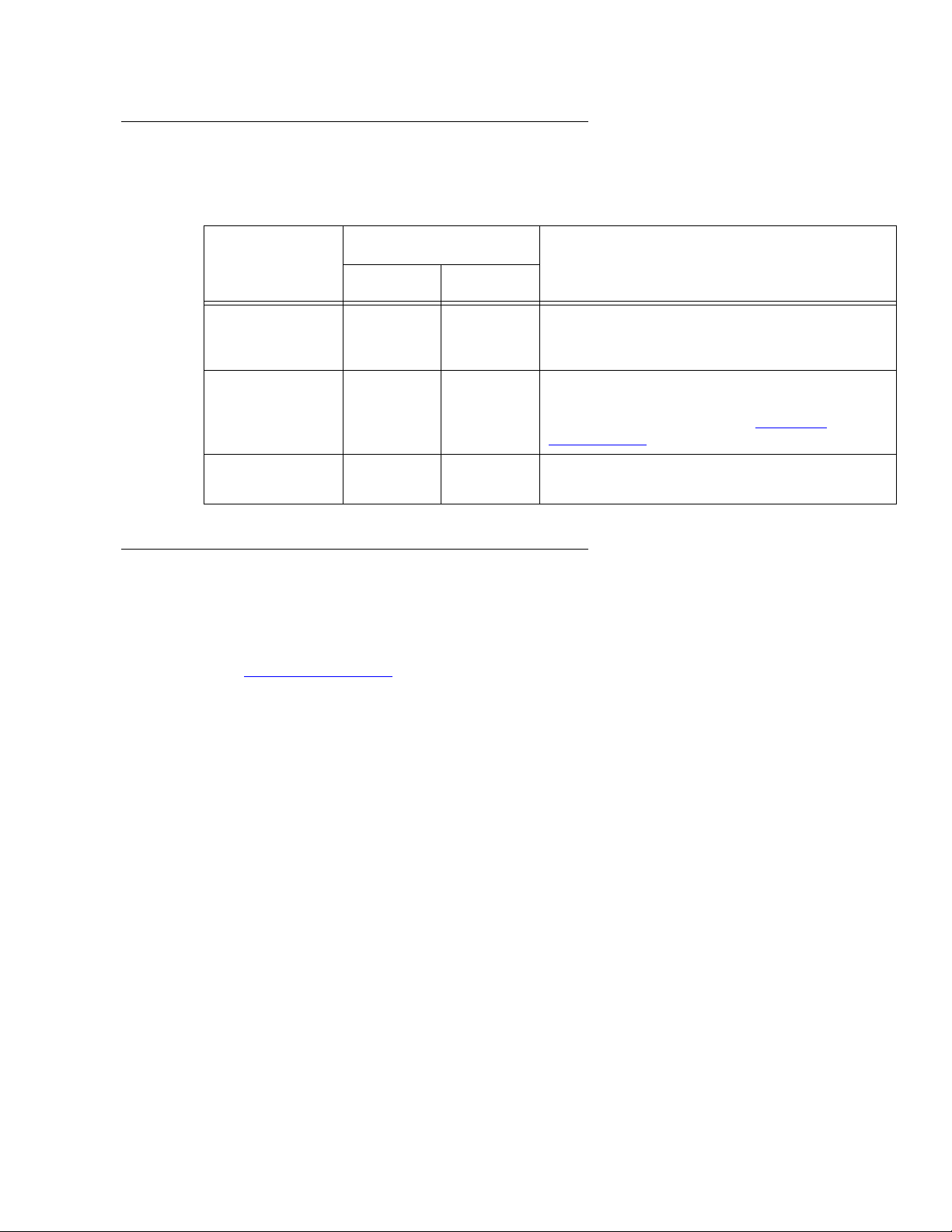
Page 17
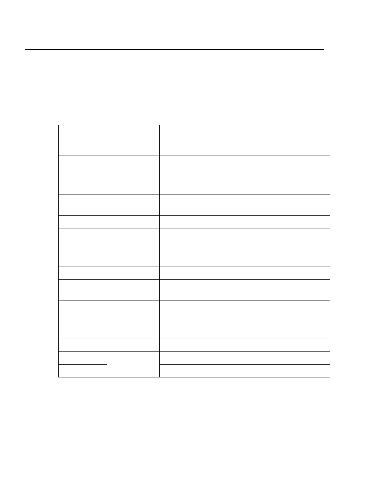
Installation
This section describes how to install the computer and related peripheral equipment. Use
the following table to check off each required procedure after completion.
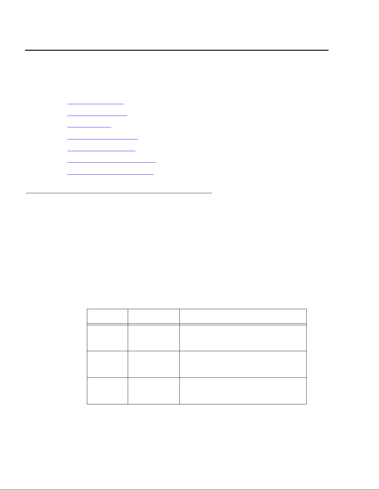
Procedure Completed
Preparing for installation
Unpacking and inventorying the equipment
Setting up power
Peripheral connectivity
Connecting the monitor, keyboard, and mouse
Connecting the remote console modem
Connecting the RSC for remote access (optional)
Connecting the switch link
Turning on the system and verifying POST
Identifying installed PCI cards
Setting the remote console modem options
Turning the system over for provisioning
on page 28
on page 18
on page 22
on page 29
on page 31
on page 32
on page 34
on page 35
on page 39
on page 41
on page 48
on page 33
Issue 2.0 June 2004 17
Page 18
Installation
Preparing for installation
This section contains the following information that will help you prepare for the computer
installation:
● Safety precautions on page 18
● System precautions on page 19
● Required tools on page 19
● Electrical specifications on page 20
● Physical specifications on page 20
● Service access specifications on page 21
● Environmental specifications on page 21
Safety precautions
For your protection, observe the following safety precautions when setting up your
equipment:
● Follow all cautions, warnings, and instructions that are marked on the equipment.
● Never push objects of any kind through openings in the equipment. Objects could touch
dangerous voltage points or short out components, resulting in fire or electric shock.
● When moving the computer, be careful not to unplug any power or data cables.
● Refer servicing of equipment to qualified personnel.
● To protect both yourself and the equipment, observe the following precautions.
Item Problem Precaution
Wrist or
foot strap
ESD Wear a conductive wrist strap or foot
strap when handling printed circuit
boards.
Cover
panels
Card slot
filler
panels
System
damage and
overheating
System
damage and
overheating
Reinstall all cabinet cover panels after
you perform any service work on the
system.
Make sure that a filler panel is installed
on all empty card slots.
18 Avaya CMS Sun Fire V880 Computer Hardware Installation, Maintenance, and Troubleshooting
Page 19

System precautions
Ensure that the voltage and frequency of the power outlet that is used matches the
electrical rating labels on the equipment.
Wear antistatic wrist straps when handling any magnetic storage devices, CPU/Memory
boards, or other printed circuit boards.
The computer has three autoranging power supplies that use nominal input voltages
of 100 to 240 V AC at 47 to 63 Hz. Sun products are designed to work with single-phase
power systems with a grounded neutral conductor. To reduce the risk of electric shock, do
not plug Sun products into another type of power source. Contact your facilities manager
or qualified electrician if you are unsure of what type of power is supplied to your building.
Avaya recommends that you use one of the following power schemes:
● Connect the computer using two (2) 2KVA Uninterruptible Power Supplies (UPS) (or
equivalent), each powered by a nonswitched, dedicated, 15-amp circuit. Connect two of
the power supplies to one UPS, and the third power supply to the second UPS. The
monitor and external peripherals can also be connected to the second UPS.
Preparing for installation
● If not using a UPS, each power supply should be connected to a nonswitched,
dedicated, 15-amp circuit. The monitor and external peripherals should be connected to
a separate circuit.
Each of the following items require a separate power cord:
● Power supplies in the computer (3 power cords)
● External peripherals
● Monitor
!
WARNING:
WARNING: Do not make mechanical or electrical modifications to the cabinet. Sun
Microsystems is not responsible for regulatory compliance of modified
cabinets.
Required tools
You need the following tools to do the installation:
● Phillips #2 screwdriver
● Needle-nose pliers
● ESD grounding wrist strap
● Antistatic mat
Issue 2.0 June 2004 19
Page 20
Installation
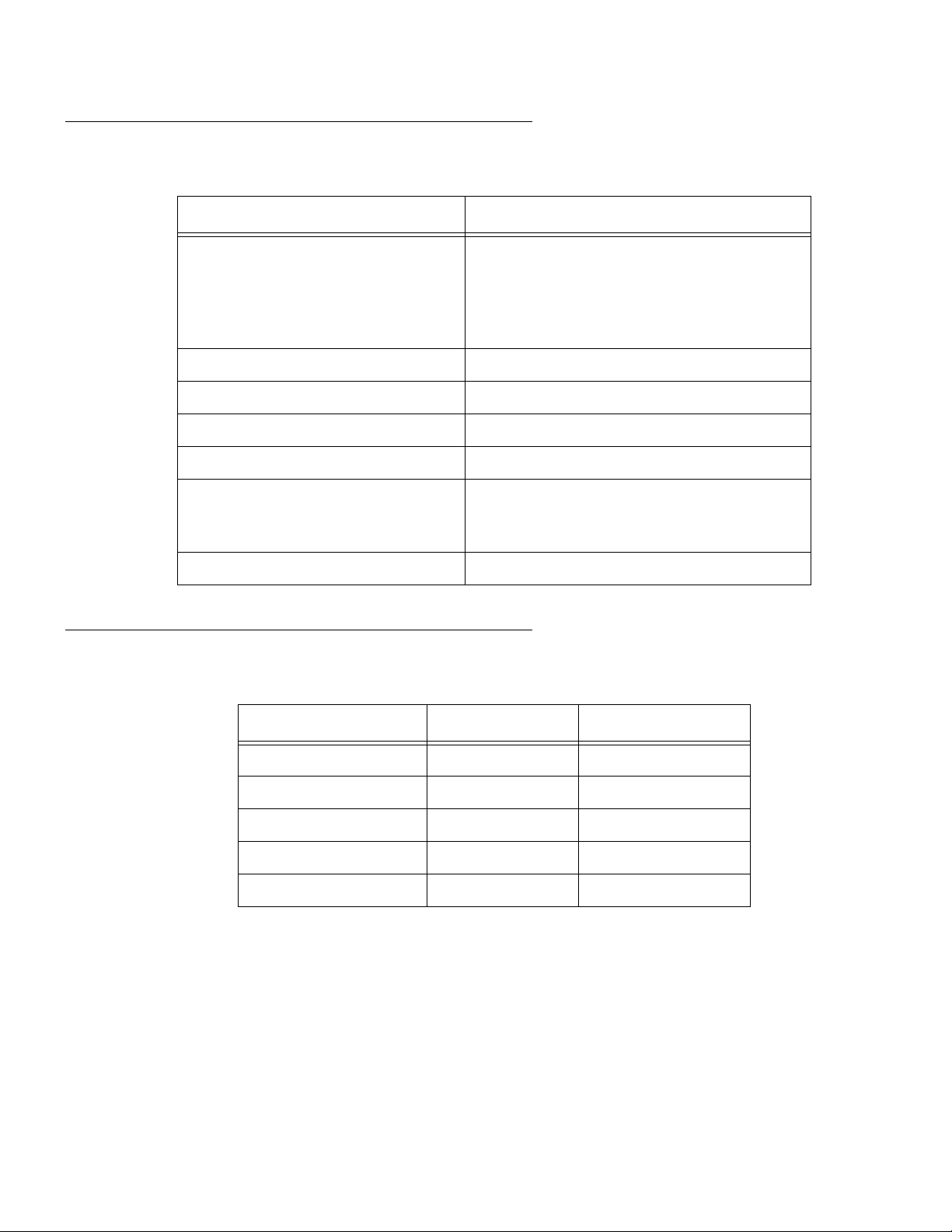
Electrical specifications
Parameter Value
Input
● Nominal voltage range
● Maximum current AC RMS
● AC operating range
● Nominal frequencies
Maximum DC power output 2240 W
Maximum AC power consumption 3000 W
Maximum heat dissipation 10308 BTU/hr
Volt-ampere rating 1515 VA with 1120 Watt load (PF=0.99)
Wall plug type
● United States
● Non-United States
● 100-240 V AC, autoranging
● 15.0 A @100 VAC (each power supply)
● 90-264 V rms, 47-63Hz
● 50 Hz or 60 Hz
● NEMA 5-15P
● Power cords must be obtained locally
CPU plug type IEC 320
Physical specifications
Parameter English value Metric value
Height (with casters) 28.1 inches 71.4 centimeters
Width 18.9 inches 48.0 centimeters
Depth 32.9 inches 83.6 centimeters
Weight (min-max)
Power cords 8.2 feet 2.5 meters
1. The actual weight depends on the installed options.
1
194-288 pounds 88-130.6 kilograms
20 Avaya CMS Sun Fire V880 Computer Hardware Installation, Maintenance, and Troubleshooting
Page 21
Service access specifications
Parameter English value Metric value
Front 36 inches 91 centimeters
Rear 36 inches 91 centimeters
Left 36 inches 91 centimeters
Right 36 inches 91 centimeters
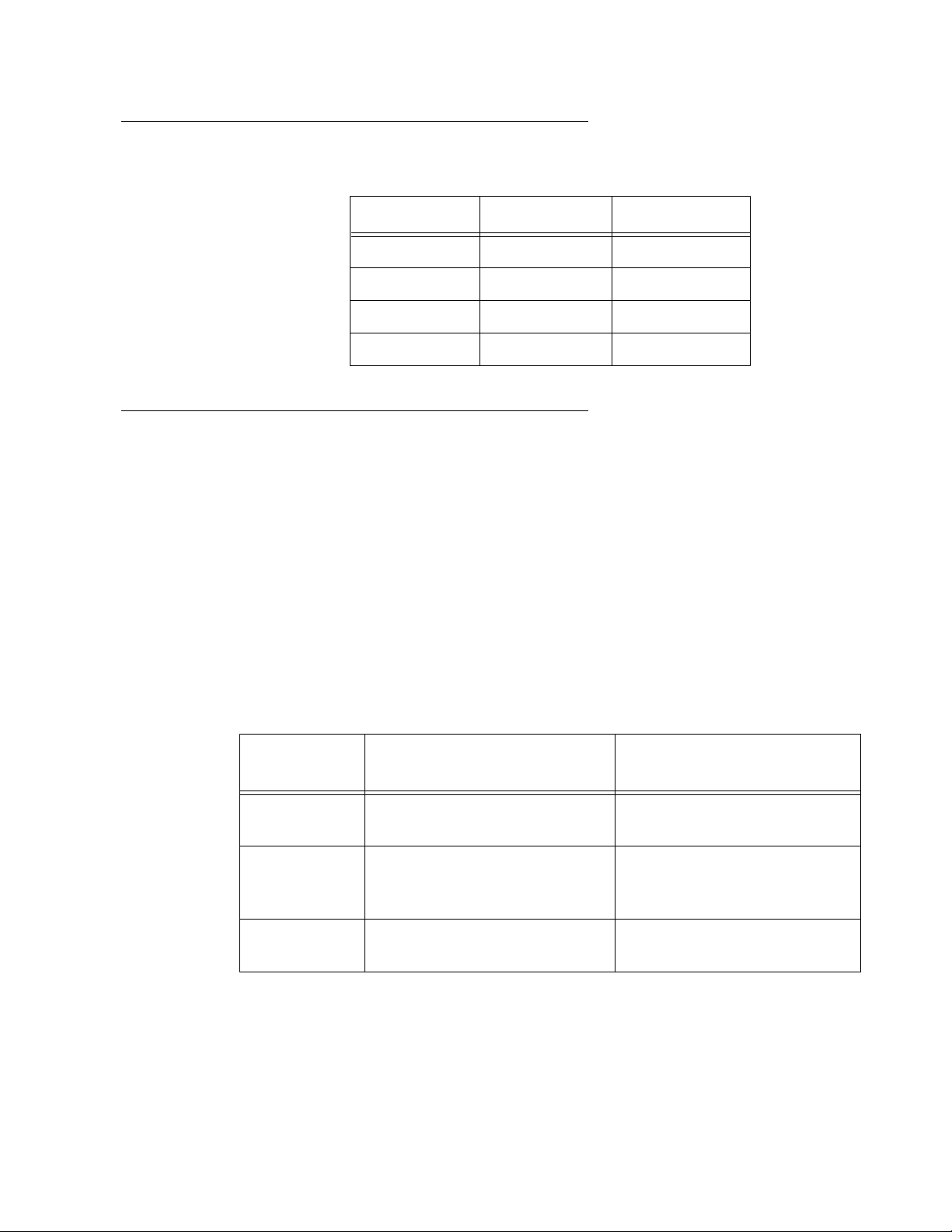
Environmental specifications
For the most reliable system operation:
● The room must have sufficient air conditioning capacity to support the cooling needs of
the entire system.
Preparing for installation
● The air conditioning system must have controls that prevent excessive temperature
changes.
● Do not turn on the computer until it has acclimated to the room temperature for at
least 24 hours.
Follow the guidelines in the table below for temperature, humidity, and altitude limits for
units in operation and for units that are not in operation (that is, units that are in transit or in
storage).
Parameter
Operating
(in service)
Temperature 41°F to 95°F (5°C to 35°C)
IEC 68-2-1, 68-2-2
Humidity
(max)
20% to 80% RH
noncondensing; 27°C max wb
IEC 68-2-2, 68-2-3
Altitude (max) 10,000 feet (3 kilometers)
IEC 68-2-40, 68-2-41
-4°F to 140°F (-20°C to 60°C)
IEC 68-2-1, 68-2-2
93% RH
noncondensing at 40°C
IEC 68-2-2, 68-2-3
40,000 feet (12 kilometers)
IEC 68-2-40, 68-2-41
Nonoperating
(not in service)
Issue 2.0 June 2004 21
Page 22
Installation
Unpacking and inventorying the equipment
!
WARNING:
WARNING: Never move the system when the power is on. Excessive movement can
cause catastrophic disk drive failure. Always turn the power off before
moving cabinets.
!
WARNING:
WARNING: Always wear an electrostatic discharge (ESD) wrist strap when handling
internal components.
!
CAUTION:
CAUTION: Always have up-to-date system backups before turning the computer off and
moving the computer.
Inspect all shipping cartons for evidence of physical damage. If a shipping carton is
damaged, request that the carrier representative be present before the carton is opened.
Unpack the computer and the associated peripheral equipment. Compare the contents of
the carton to the shipping inventory list to verify that all equipment was delivered.
In the United States, contact Avaya technical support if any parts are defective on arrival.
Contact Avaya customer service if any parts are missing.
Outside of the United States, contact your Avaya representative or distributor if any parts
are missing or defective.
This section includes the following topics:
● Parts list on page 23
● Computer layout on page 24
● Hardware options on page 27
● Rack mounting on page 27
22 Avaya CMS Sun Fire V880 Computer Hardware Installation, Maintenance, and Troubleshooting
Page 23

Parts list
Verify that you have the following components before you begin the installation:
Important: DO NOT install internal hardware shipped loose with the Sun machine at
● Sun Fire V880 cabinet (including installed cards and disk drives)
● Computer power supply AC power cords (3)
● Monitor, cable, and monitor AC power cord
● USB keyboard and cable
● USB mouse and cable
● A package of blank tapes for backups
● One tape that contains the Avaya factory configuration CMSADM filesystem backup
Unpacking and inventorying the equipment
!
!
Important:
Important:
this time. This will be done under the direction of the CMS Provisioning
Engineer at a scheduled appointment time.
● Category 5 LAN cable
● Modem and cables
● Keys
● Sun and CMS software
Note:
Note: Starting around June, 2004, CMS servers will no longer ship with tape drive
cleaning tapes. Avaya recommends that customers purchase at least one
cleaning tape as soon as the server is installed and in service.
Issue 2.0 June 2004 23
Page 24

Installation
Computer layout
Familiarize yourself with the layout of the computer. The minimum configuration for the
computer is as follows:
● One CPU/Memory board (with two UltraSPARC lIl processors and 4-GB memory)
● Four disk drives, mirrored two plus two
● One built-in ethernet port
● One graphics PCI card installed in slot 7
● Either:
- One SunSwift PCI card installed in slot 0, or
- One Dual FastEthernet and Dual SCSI card installed in slot 0
● Three power supplies and power cords
● One DVD-ROM drive
● One tape drive
● Two USB ports
● One serial port
24 Avaya CMS Sun Fire V880 Computer Hardware Installation, Maintenance, and Troubleshooting
Page 25
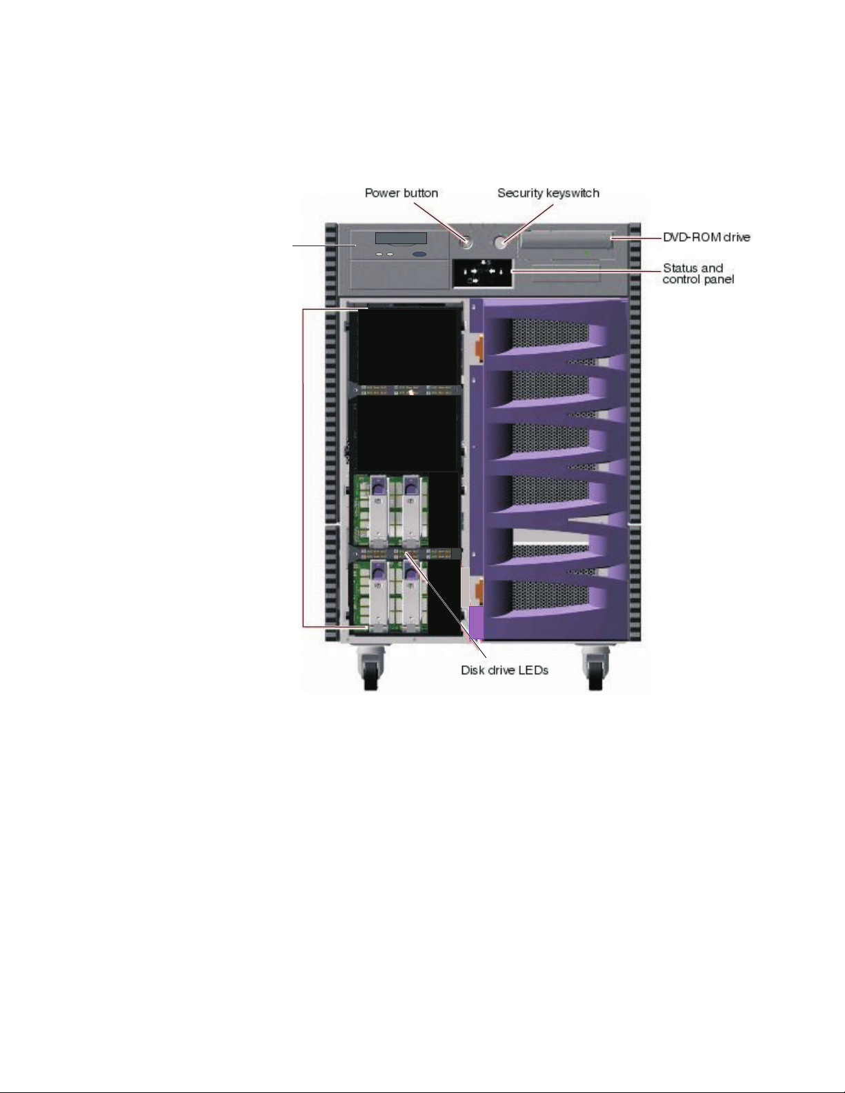
Front panel
The following figure shows the front of the computer with the disk drive door open.
Unpacking and inventorying the equipment
Tape drive
Disk drive
slots
v880_front.cdr
Issue 2.0 June 2004 25
Page 26
Installation
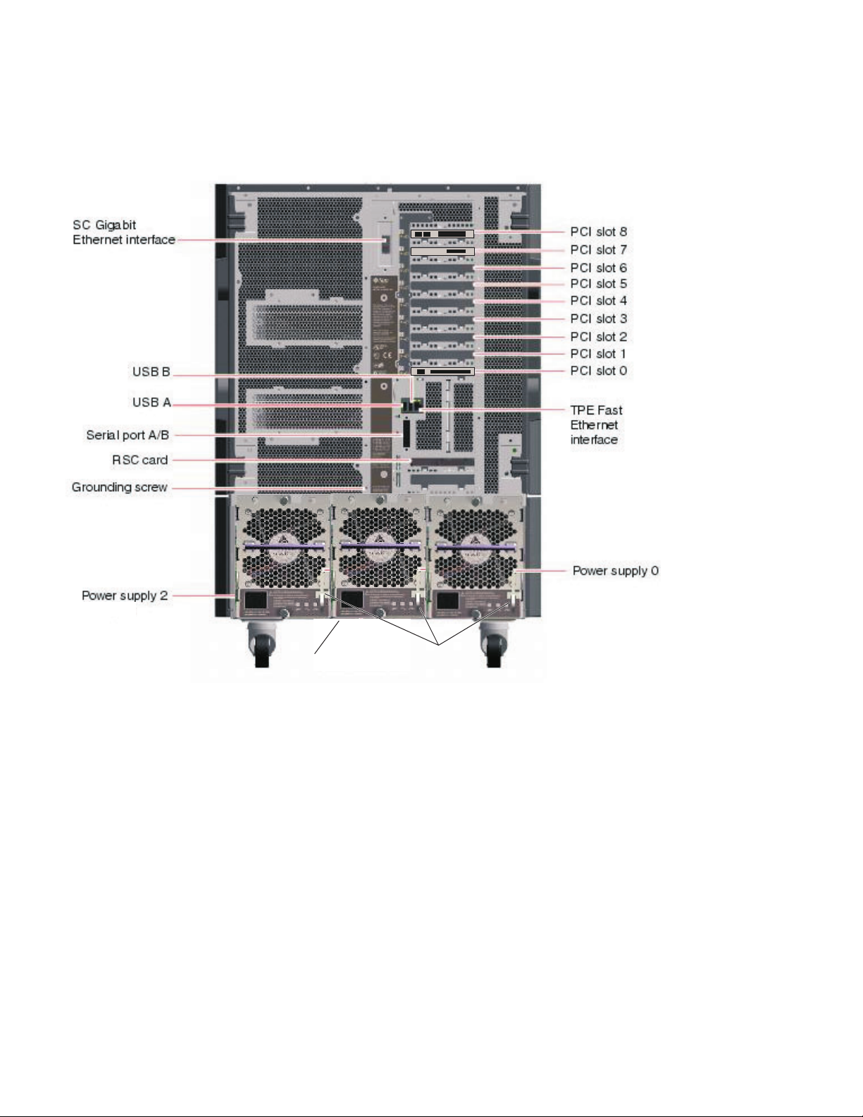
Back panel
The following figure shows the back panel of the computer.
(not used)
Power supply 1
Power cord
strain relief ties
v880_rear.cdr
(Graphics card)
(SunSwift card, or
Dual FastEthernet
and Dual SCSI card
)
26 Avaya CMS Sun Fire V880 Computer Hardware Installation, Maintenance, and Troubleshooting
Page 27
Hardware options
The following table lists the hardware options for the computer.
.
Option Quantity Comments
Unpacking and inventorying the equipment
Minimum Maximum
CPU/Memory
boards
PCI I/O cards 2 7 There are nine slots, but only seven slots
Disk drives 4 6 A pair of data disks can be added to the
Rack mounting
The computer can be rack mounted. For information about rack mounting, see Sun
Fire 880 Server Rackmounting Guide at the Sun documentation Web site:
http://docs.sun.com
Note:
Note: When rack mounting the computer, the technician must remove all CPU/
Memory boards, all power supplies, all CPU fan trays, and all I/O fan trays,
as described in the rack mounting guide.
1 4 The minimum configuration is one CPU/
Memory board. Each board has two CPU
modules and 4-GB memory.
may be used. For a listing of where the PCI
cards can be installed, see PCI card
configuration on page 58.
system. This will be offered in the future.
Issue 2.0 June 2004 27
Page 28
Installation
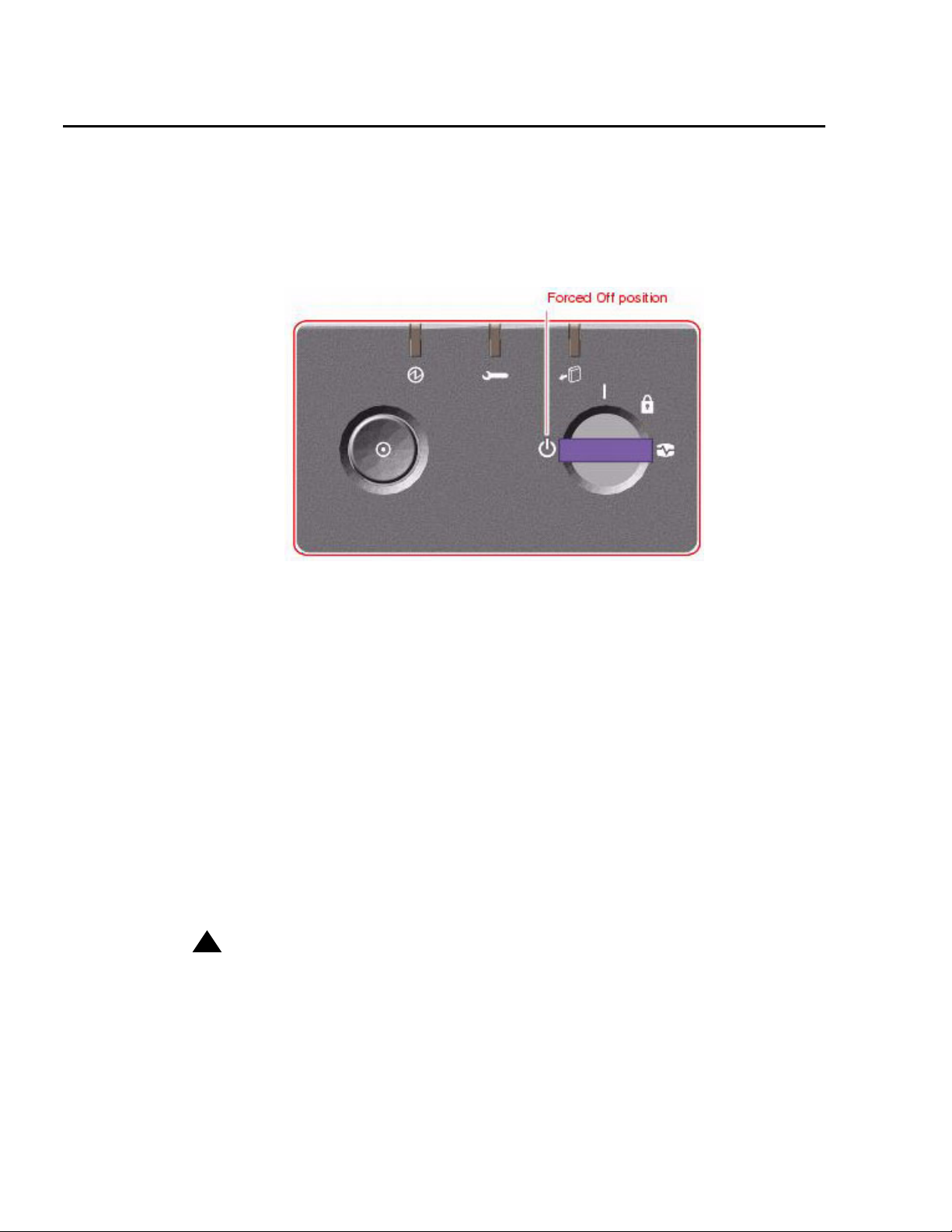
Setting up power
To set up the AC power:
1. Locate the key switch, insert the key, and turn the key switch to the Forced Off position.
See the following figure.
2. Connect the IEC 320 end of each power cord to the AC connector of each power
supply.
For installations outside of the United States and Canada, obtain three power cords for
your local configuration.
3. Route the power cord through the strain-relief tie-wrap loop located to the right of the
supply. Tighten the tie-wrap to secure the connection.
4. Plug the power cords from the computer using one of the following schemes:
● Connect the computer using two (2) 2KVA Uninterruptible Power Supplies (UPS) (or
equivalent), each powered by a nonswitched, dedicated, 15-amp circuit. Connect
two of the power supplies to one UPS, and the third power supply to the second
UPS. The monitor and external peripherals can also be connected to the second
UPS.
● If not using a UPS, each power supply should be connected to a nonswitched,
dedicated, 15-amp circuit. The monitor and external peripherals should be
connected to a separate circuit.
!
!
Important:
Important:
Important: Do not turn on power at this time.
28 Avaya CMS Sun Fire V880 Computer Hardware Installation, Maintenance, and Troubleshooting
Page 29
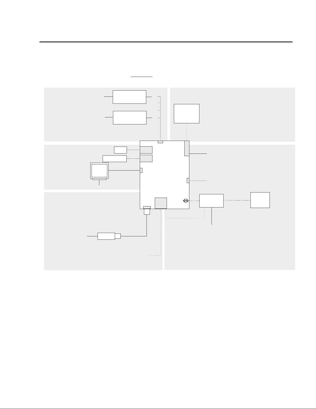
Peripheral connectivity
The following figure shows in general how equipment is connected to the computer. The
callouts are described in Parts list
Peripheral connectivity
on page 30.
X.25 switch links
One HSI/P card is used
for up to four ACDs.
A second HSI/P card is
needed for five to eight ACDs.
For detailed switch link connectivity, see
CMS Switch Connections, Administration,
and Troubleshooting
, 585-215-876
System console
Keyboard
O
Monitor
M
N
AC power
Required telephone
line to remote
maintenance center
J
Modem
Remote console
Black Box
RS-449 - RS-232
interface converter
Black Box
RS-449 - RS-232
interface converter
Mouse
P
I
Optional telephone
line to remote
maintenance center
KL
C
C
USB
port
USB
port
Graphics
card
Serial
Port A
H
B
A
HSI/P
card
Dual FastEthernet
and Dual SCSI card
RSC
card
S
M
E
e
o
t
r
d
h
G
External SCSI
tape drive
for data
migration only
SunSwift
card, or
FastEthernet
card
Built-in
TPE Fast
Ethernet
Interface
Optional
ethernet
link for
services
access
SCSI port
D
Ethernet
E
F
Ethernet port for switch link, R7 and later
port
F
(supports up to eight ACDs)
For detailed switch link connectivity, see
CMS Switch Connections, Administration,
and Troubleshooting
Optional ethernet port (two cards maximum)
Network
hub
To customer
network for
CMS Supervisor,
network printers,
and LAN backup
External SCSI devices
, 585-215-876
NTS
To serial
terminals, printers,
and modems
For detailed network hub and NTS
connectivity, see
Printers, and Modems
CMS Terminals,
, 585-215-874
Ethernet LAN connections
sunfire880conn.cdr
Issue 2.0 June 2004 29
Page 30
Installation
Parts list
The following table lists the parts that are required to connect most of the external devices
to the computer. For information about connecting terminals, printers, and modems to the
computer, see Avaya CMS Terminals, Printers, and Modems. For information about switch
connections for CMS, see Avaya Call Management System Switch Connections,
Administration, and Troubleshooting.
Connectivity
diagram call
out
1
A
1
B
Comcode or
Description
part of
comcode
408128288 HSI/P card (up to two may be installed)
HSI/P quad cable (1 per HSI/P card)
C 407086818 RS-449 cable (10 feet, 3 meters)
DN/A
2
SunSwift card, or
Dual FastEthernet and Dual SCSI card
1
E
700230105 FastEthernet 10/100 Mbps card
F 407086826 Category 5 UTP cable (10 feet, 3 meters)
G 846362754 DB25-to-RJ45 ACU modem adapter
H 846983039 10-wire modular cord (10 feet, 3 meters)
I 846362770 RJ45-to-DB25 remote console adapter
J 407633999
Varie s
K
L
M
N
O
P
1
1
1
1
1
1
N/A
N/A
N/A
N/A
N/A
2
2
2
2
2
Sportster Model 839 33.6 remote console modem
Comsphere 3910 remote console modem
Graphics card
Monitor cable
Monitor
Monitor AC power cord
USB keyboard with cable
USB mouse with cable
1. Sun Microsystems provides maintenance sparing for these parts.
2. The comcode for this bundle changes regularly and may not be ordered for maintenance spares, so
it is not listed in the table. This bundle includes the processor, peripherals, and other equipment.
30 Avaya CMS Sun Fire V880 Computer Hardware Installation, Maintenance, and Troubleshooting
Page 31

Connecting the monitor, keyboard, and mouse
Connecting the monitor, keyboard, and mouse
To connect the monitor, keyboard, and mouse to the computer:
1. Attach the monitor video cable to the graphics card, which is installed in slot 7. Tighten
the thumbscrews to secure the connection. See the following figure.
2. Connect the monitor power cord to an approved AC power outlet.
3. Attach the USB keyboard cable to one of the USB ports.
4. Attach the USB mouse cable to the other USB port.
Issue 2.0 June 2004 31
Page 32

Installation
Connecting the remote console modem
The remote console modem allows personnel at a remote support center to dial in and
perform maintenance on the computer. The modem is a U.S. Robotics Sportster 33.6
Faxmodem, a Paradyne Comsphere 3910 modem, or a modem provided locally.
The following figure shows remote console modem connectivity.
.
Telephone line
to remote
maintenance center
Modem
C
B
A
Serial
port
Key:
A = DB25-RJ45 ACU modem adapter
B = 10-wire modular cord
C = RJ45-DB25 remote console adapter
remote_console.cdr
To connect the remote console modem:
1. Connect the DB25-to-RJ45 ACU modem adapter (A) to the serial port on the back of
the computer.
2. Connect the 10-wire modular cord (B) to the modular end of the ACU modem
adapter (A).
3. Connect the other end of the 10-wire modular cord (B) to the modular end of the
RJ45-to-DB25 remote console adapter (C).
4. Connect the remote console adapter (C) to the RS-232C port on the modem. The
RS-232C port on the Comsphere 3910 is labeled "DTE1."
5. Connect the telephone line to the jack labeled "LINE" on the Sportster modem, or
labeled "DIAL" on the Comsphere 3910 modem.
6. Connect the power cable to the modem and plug it into a socket.
Do not turn on the power yet. Instructions for turning on the modem are given in Setting the
remote console modem options on page 41.
32 Avaya CMS Sun Fire V880 Computer Hardware Installation, Maintenance, and Troubleshooting
Page 33

Connecting the RSC for remote access (optional)
Connecting the RSC for remote access (optional)
The RSC card provides the following optional connections:
● An ethernet connection to the customer network that allows personnel to telnet into
the RSC to perform provisioning, maintenance, and troubleshooting. This connection
can also be used to set up e-mail alerts for system problems. For more information
about e-mail alerts, see Sun Remote System Control (RSC) User’s Guide at the Sun
documentation Web site, http://docs.sun.com
● A built-in modem that allows personnel to dial in to the RSC and perform provisioning,
maintenance, and troubleshooting. This connection can also be used to set up pager
alerts for system problems. For more information about pager alerts, see Sun Remote
System Control (RSC) User’s Guide at the Sun documentation Web site, http://
docs.sun.com.
Note:
Note: The serial port on the RSC is not used for CMS.
The following figure shows the connections to the RSC card.
.
Customer
network
Hub
Category 5 RJ45
RSC
LAN
port
modular cord
rsc_connect.cdr
RSC
modem
port
RJ11 analog
phone cord
Telephone line
to remote
maintenance center
Issue 2.0 June 2004 33
Page 34

Installation
Connecting the switch link
Use either of the following two ways to connect the CMS computer to a switch:
● TCP/IP over a local area network (LAN)
● X.25 protocol over a hard-wired or switched link (not supported for CMS R12 and later)
One CMS computer can collect data from several switches. To the CMS computer, each
switch represents one ACD. You can have all switches connected using TCP/IP, all
switches connected using X.25 protocol (not supported for CMS R12 and later), or some
combination of the two protocols.
For detailed information about how to connect and administer the switch link, see Avaya
Call Management System Switch Connections, Administration, and Troubleshooting.
34 Avaya CMS Sun Fire V880 Computer Hardware Installation, Maintenance, and Troubleshooting
Page 35

Turning on the system and verifying POST
Turning on the system and verifying POST
Once you assemble the system, including the loose hardware that is shipped with the
system that you installed with help from CMS Provisioning, turn on the system and verify
the results of the Power-On Self Test (POST).
To turn on the system and verify POST:
1. Verify that the key switch is in the Forced Off position. See the following figure.
2. If using one or more UPSs, plug the power cord of each UPS into a dedicated circuit. If
not using a UPS, plug the power cords for each power supply into an outlet on a
dedicated 15-amp circuit.
3. Turn on the power to the UPS units, if UPS units are installed.
4. Turn on the system monitor.
Issue 2.0 June 2004 35
Page 36

Installation
5. Turn the key switch to the normal On position. See the following figure.
6. Press and release the power button to the left of the key switch to turn on the system.
Note:
Note: The POST diagnostics occurs each time that you turn on the system. The
POST tests the basic system components. This may take several minutes.
As the system powers up, the power LED on the monitor flashes.
7. Press Stop+A simultaneously as soon as the monitor power LED lights steadily and
the Sun logo is displayed on the monitor.
The ok prompt is displayed.
8. Enter the following commands:
setenv auto-boot? false
reset-all
The system resets to the ok prompt.
36 Avaya CMS Sun Fire V880 Computer Hardware Installation, Maintenance, and Troubleshooting
Page 37

Turning on the system and verifying POST
9. Enter:
probe-scsi-all
This verifies that the system sees the disk drives and backplane, the tape drive, and
the DVD-ROM drive. A message that is similar to the following is displayed:
/pci@8,600000/SUNW,qlc@2
LiD HA LUN --- Port WWN --- -----Disk description -----
0 0 0 21000004cf72f08f SEAGATE ST373405FSUN3660438
1 1 0 21000004cf721553 SEAGATE ST373405FSUN3660438
6 6 0 508002000016b5b1 SUNW SUNWGS INT FCBPL9224
3 3 0 21000004cf72114b SEAGATE ST373405FSUN3660438
4 4 0 21000004cf7211ae SEAGATE ST373405FSUN3660438
/pci@8,700000/scsi@1
Target 5
Unit 0 Removeable Tape HP C5683A C005
Target 6
Unit 0 Removeable Read Only device TOSHIBA DVD-ROM SD-M14011009
/pci@8,700000/pci@5/SUNW,1sptwo@4
10. Verify that all of the devices are recognized. If the devices are not recognized, see
Troubleshooting disk drives and DVD-ROM drives
on page 180 for more information.
11. When you have verified that the system recognizes all of its devices, enter the
following commands:
!
CAUTION:
CAUTION: If you fail to reset the auto-boot option, any reboots that you do in the future
will stop at the boot prompt instead of proceeding through the normal
boot-up process.
setenv auto-boot? true
boot
The system reboots.
Issue 2.0 June 2004 37
Page 38

Installation
12. Turn the key switch to the Locked position. This prevents anyone from accidentally
turning off the system. See the following figure.
38 Avaya CMS Sun Fire V880 Computer Hardware Installation, Maintenance, and Troubleshooting
Page 39

Identifying installed PCI cards
Identifying installed PCI cards
If there are problems with the PCI cards, do the following to troubleshoot the problem. If all
PCI cards are operational, you can skip this procedure.
At the command prompt, enter:
/usr/platform/‘uname -m‘/sbin/prtdiag -v | pg
In the section IO Cards, there is a listing of the PCI cards. The following are examples of
some of the entries you may see. The display you see depends on your specific
configuration.
.
.
========================= IO Cards =========================
Bus Max
IO Port Bus Freq Bus Dev,
Brd Type ID Side Slot MHz Freq Func State Name
Model
---- ---- ---- ---- ---- ---- ---- ---- ----- ------------------------------------------------------
I/O PCI 8 B 3 33 33 2,0 ok pci1214,334-pci1214,334.10
I/O PCI 8 B 1 33 33 4,0 ok pci108e,1000-pci108e,1000.1
I/O PCI 8 B 1 33 33 4,1 ok SUNW,hme-pci108e,1001 SUNW,qsi-cheerio
I/O PCI 9 B 0 33 33 3,0 ok pci-pci8086,b154.0/network (netw+PCI-BRIDGE
I/O PCI 9 B 0 33 33 0,0 ok network-pci100b,35.30 SUNW,pci-ce/pci-bridge
I/O PCI 9 B 0 33 33 1,0 ok network-pci100b,35.30 SUNW,pci-ce/pci-bridge
I/O PCI 9 B 0 33 33 2,0 ok scsi-pci1000,b.7/disk (block) device on pci-bridge
I/O PCI 9 B 0 33 33 2,1 ok scsi-pci1000,b.7/disk (block) device on pci-bridge
I/O PCI 9 A 7 66 66 2,0 ok SUNW,XVR-100 SUNW,375-3181
.
.
In this example:
● Slot 0 has a Dual FastEthernet and Dual SCSI card. There is more than one entry for a
this card because the card has two SCSI ports and two Ethernet ports.
● Slot 1 has a FastEthernet card. There is more than one entry for the FastEthernet card
because the card has the ethernet port and a Media Independent Interface (MII) port
(not used with CMS).
● Slot 3 has an HSI/P card.
● Slot 7 has a graphics card.
Issue 2.0 June 2004 39
Page 40

Installation
Ap_Id Type Receptacle Occupant Condition
pcisch0:hpc1_slot0 pci-pci/hp connected configured ok
pcisch0:hpc1_slot1 bridge/hp connected configured ok
pcisch0:hpc1_slot2 unknown empty unconfigured unknown
pcisch0:hpc1_slot3 unknown/hp connected configured ok
pcisch2:hpc2_slot4 unknown empty unconfigured unknown
pcisch2:hpc2_slot5 unknown empty unconfigured unknown
pcisch2:hpc2_slot6 unknown empty unconfigured unknown
pcisch3:hpc0_slot7 vgs8514/hp connected configured ok
pcisch3:hpc0_slot8 unknown empty unconfigured unknown
You can also use the cfgadm command to display the following information about the
cards in the PCI slots:
.
.
.
.
In the above example:
● Slot 0 has a Dual FastEthernet and Dual SCSI card.
● Slot 1 has a FastEthernet card.
● Slot 3 has an HSI/P card.
● Slot 7 has a graphics card.
40 Avaya CMS Sun Fire V880 Computer Hardware Installation, Maintenance, and Troubleshooting
Page 41

Setting the remote console modem options
Setting the remote console modem options
The computer uses the U.S. Robotics Sportster 33.6 Faxmodem or the Paradyne
Comsphere 3910 modem for remote console access. The options for any other modems
must be set based on local instructions.
For instructions for connecting the modem, see Connecting the remote console modem
page 32.
This section includes the following topics:
● Sportster 33.6 faxmodem options on page 41
● Paradyne Comsphere 3910 modem options on page 43
Sportster 33.6 faxmodem options
To set the options on the Sportster 33.6 faxmodem:
1. Set DIP switches 1, 3, 7, and 8 on the back panel of the Sportster modem to the down
(ON) position, and switches 2, 4, 5, and 6 to the up (OFF) position.
2. Turn on the remote console modem.
3. At the system console, log in as root.
4. Enter:
/cms/install/bin/abcadm -r ttya
The following message is displayed:
on
ttya is currently set to be incoming
Are you sure you want to change it? [y,n,?]
5. Enter: y
The following message is displayed:
ttya administration removed
The port monitor turns off.
Issue 2.0 June 2004 41
Page 42

Installation
6. Enter:
cu -s 9600 -b 8 -l cua/a
The following message is displayed:
Connected
7. Enter the following commands:
at&f1 (loads the factory default configuration into active memory)
at&w0 (writes the current configuration to NVRAM template Y0)
Note:
Note: Use numerical ones and zeros when entering the options.
8. After you enter the options, disconnect from the modem by entering a tilde and a
period (~.).
9. Set DIP switches 4 and 8 on the back panel of the Sportster modem to the down (ON)
position. Set all other DIP switches to the up (OFF) position.
10. Reset the modem by turning the power off and back on.
11. Enter:
/cms/install/bin/abcadm -i -b 9600 ttya
The Terminal Ready (TR) LED lights on the modem and the following message is
displayed:
ttya set to incoming port 9600 baud
12. If the TR LED is not lit, enter:
ps -ef | grep sac
A message similar to the following should be displayed:
root 377 1 0 14:39:30 ? 0:00 /usr/lib/saf/sac -t 300
root 9723 9666 0 09:16:26 pts/9 0:00 grep sac
Additional references - For additional information, see the U.S. Robotics Sportster
Modems Users Guide.
42 Avaya CMS Sun Fire V880 Computer Hardware Installation, Maintenance, and Troubleshooting
Page 43

Setting the remote console modem options
Paradyne Comsphere 3910 modem options
The Paradyne Comsphere 3910 modem is used for many locations outside of the United
States.
This section includes the following topics:
● Recommended options on page 43
● Option buttons on page 43
● Setting the options on page 44
Recommended options
The recommended options for the Comsphere 3910 modem include selecting the
factory-preset defaults for "UNIX_Dial" with the following two changes:
● Change Asynchronous DTE Rate to 9600
● Change Dial Line Rate to 9600 (V32b)
Option buttons
The seven buttons that are used to set the modem options are:
● Single up arrow - Move up one level in the menu tree.
● Double up arrow - Move to the top-level menu.
● Left arrow - Move to the previous choice for the current level in the menu tree.
● Right arrow - Move to subsequent choice for the current level in the menu tree.
● Function 1 (F1) - Select the choice, if any, that is currently displayed above F1.
● Function 2 (F2) - Select the choice, if any, that is currently displayed above F2.
Issue 2.0 June 2004 43
Page 44

Installation
p
● Function 3 (F3) - Select the choice, if any, that is currently displayed above F3.
Setting the options
Single up
arrow
Left
arrow
Display
Function keys
Double u
arrow
Right
arrow
3910.cdr
To set the options on the Comsphere 3910, use the following procedures:
Configuring Factory/Async_Dial
1. Press F2 to select "Configure."
"Ld EditArea frm" is displayed.
2. Press the Right Arrow four times.
"Factory" is displayed.
3. Press F1 to select "Factory."
"Ld Fact Preset:" is displayed.
4. Press Right Arrow four times.
5. Press F1 to select "UNIX_Dial."
6. Press F3 to select "Save."
"Sav EditArea to" is displayed.
7. Press F1 to save to "Active(Saved)."
Since you are changing the active area to a new set of options (that is, "Factory/
Async_Dial"), the modem automatically performs another Power-On-Self-Test (POST).
Since the new options match the way the modem is connected, the ALRM LED does
not turn red. "Idle: 19.2" and "Status Configure" are displayed. To return to the top-level
menu, press the Double Up Arrow.
44 Avaya CMS Sun Fire V880 Computer Hardware Installation, Maintenance, and Troubleshooting
Page 45

Setting the remote console modem options
Setting the data rate
1. Press F2 to select "Configure."
"Ld EditArea frm" is displayed.
2. Press the Right Arrow once.
"Active(Saved)" is displayed.
3. Press F1.
"Choose Function" is displayed.
4. Press F1 to select "Edit."
"Edit StrapGroup" is displayed.
5. Press F1 to select "DTE_Interface."
"Async/Sync Mode" is displayed.
6. Press F1 to select "Nxt."
"Async DTE Rate" is displayed.
7. Press the Right Arrow five times to display "9600."
8. Press F2 to select "9600."
Setting the handshake options
1. Press F1 for "Nxt."
"Asyn #Data Bits (8)" is displayed.
2. Press F1 for "Nxt."
"Asyn Parity Bit (None)" is displayed.
3. Press F1 for "Nxt."
"Asyn #Stop Bits (1)" is displayed.
4. Press F1 for "Nxt."
"DTR Action (Ignore)" is displayed.
5. Press F1 for "Nxt."
"DSR Control (Forced_On)" is displayed.
6. Press F1 for "Nxt."
"RTS Action (Ignore)" is displayed.
7. Press F1 for "Nxt."
"CTS Control (WinkWhenDisc)" is displayed.
8. Press F1 for "Nxt."
"RTS/CTS Delay (0 msec)" is displayed.
Issue 2.0 June 2004 45
Page 46

Installation
9. Press F1 for "Nxt."
"LSD Control (WinkWhenDisc)" is displayed.
10. Press F1 for "Nxt."
"CT111_Rate Cntl (Disable)" is displayed.
11. Press F1 for "Nxt."
"DTE_Rate=VF (Disable)" is displayed.
12. Press F1 for "Nxt."
"Extend Main Ch. (Disable)" is displayed.
13. Press F1 for "End."
"Edit StrapGroup" is displayed.
Setting the Dial_Line strap group
1. Press the Right Arrow three times to get to the "Dial_Line" strap group. Nothing needs
to be changed for CMS in the "DTE_Dialer" or "Line_Dialer" strap groups, so you can
skip them.
2. Press F1 to edit the "Dial_Line" strap group.
"Dial Line Rate" is displayed.
3. Press the Right Arrow four times for "9600(V32b)."
4. Press F2 to select "9600(V32b)."
5. Press F1 for "Nxt."
"V32bis Automode (Enable)" is displayed.
6. Press F1 for "Nxt."
"V32bis Autorate (Enable)" is displayed.
7. Press F1 for "Nxt."
"Dial Tx Level (Permissv (-9))" is displayed.
8. Press F1 for "Nxt."
"V22b Guard Tone (Disable)" is displayed.
9. Press F1 for "Nxt."
"V32bis Train (Long)" is displayed.
10. Press F1 for "End."
"Edit StrapGroup" is displayed. Do not change he other strap groups ("V42/MNP/
Buffer," "Test," "Misc," and "Security") for CMS.
46 Avaya CMS Sun Fire V880 Computer Hardware Installation, Maintenance, and Troubleshooting
Page 47

Setting the remote console modem options
Saving your settings
1. Press the Single Up Arrow to display "Choose Function" and "Edit Save."
2. Press F3 to select "Save."
"Save EditArea to" is displayed.
3. Press F1 to select "Active(Saved)."
"Command Complete" is displayed.
4. Press the Single Up Arrow again to display "Save EditArea to."
5. Press the Right Arrow once to select "Customer 1."
6. Press F1 to save to "Customer 1."
"Command Complete" is displayed.
7. Press the Double Up Arrow.
"Idle: 9600" and "Status Configure" are displayed. If the modem is turned off, it should
return to this state when it is turned on.
8. To check the status of the Comsphere 3910 modem, use the "Status" choice in the
top-level menu, or use the Right and Left Arrow buttons to view other top-level menu
choices.
Issue 2.0 June 2004 47
Page 48

Installation
Turning the system over for provisioning
After completing the physical installation of the system, the installation continues with
software provisioning. This is often done with the support of the Avaya CMS Provisioning
group. Provisioning the system consists of the following:
● Setting up CMS
● Authorizing features
● Setting up the RSC (optional)
● Adding logins and passwords
● Testing the software
To continue with provisioning, see the chapter "Turning the system over to the customer" in
the CMS software installation, maintenance, and troubleshooting document for your CMS
release.
48 Avaya CMS Sun Fire V880 Computer Hardware Installation, Maintenance, and Troubleshooting
Page 49

Maintenance
This section describes the following maintenance procedures:
● Precautions on page 50
● Computer layout on page 51
● Turning the computer off and on on page 53
● Accessing components inside the computer on page 55
● Using an ESD wrist strap on page 58
● Maintaining PCI cards on page 59
● Replacing the RSC card on page 94
● Maintaining disk drives on page 99
● Replacing the DVD-ROM drive on page 122
● Maintaining tape drives on page 126
● Maintaining CPU/Memory boards on page 136
● Replacing a power supply on page 147
Issue 2.0 June 2004 49
Page 50

Maintenance
Precautions
!
DANGER
DANGER: Hazardous energy levels are present inside the system when the system
:
remains connected to a power source, regardless of the key switch position.
Also, hazardous energy levels are present in the system's batteries even
when all AC power cords are disconnected. Be sure to follow the safety
procedures in the owner's guide or service manual.
!
WARNING:
WARNING: The graphics card, older Dual FastEthernet and Dual SCSI cards,
High-Speed Serial Interface/PCI (HSI/P) card, and RSC card are not
hot-pluggable cards. Before replacing these cards, you must turn off the
computer and, in the case of the RSC card, disconnect all AC power cords.
!
CAUTION:
CAUTION: Printed circuit boards and hard disk drives contain electronic components
that are extremely sensitive to static electricity. Ordinary amounts of static
from your clothes or the work environment can destroy components. Do not
touch the components or any metal parts without taking proper antistatic
precautions. See Using an ESD wrist strap
!
CAUTION:
CAUTION: Avoid keeping doors open for extended periods of time while the system is
on page 58 for more information.
operating. All doors must be closed to prevent automatic thermal shutdown.
50 Avaya CMS Sun Fire V880 Computer Hardware Installation, Maintenance, and Troubleshooting
Page 51

Computer layout
The following figures identify the basic hardware components of the computer:
● Front panel on page 51
● Rear panel on page 52
Front panel
The following figure shows the front of the computer with the disk drive door open.
Tape drive
Computer layout
Disk drive
slots
v880_front.cdr
Issue 2.0 June 2004 51
Page 52

Maintenance
Rear panel
The following figure shows the back panel of the computer.
(not used)
(Reserved for future use)
(Graphics card)
(Not used)
(Not used)
(Second HSI/P card, optional)
(First HSI/P card, optional)
(Second FastEthernet card, optional)
(First FastEthernet card, optional)
(SunSwift card, or)Dual FastEthernet
and Dual SCSI card
v880_rear_cards.cdr
Power supply 1
Power cord
strain relief ties
52 Avaya CMS Sun Fire V880 Computer Hardware Installation, Maintenance, and Troubleshooting
Page 53

Turning the computer off and on
Use the following procedures to turn the computer off and on.
Turning off the computer
1. Log in to the system as root.
2. Enter:
/usr/sbin/shutdown -y -i0 -g0
This shuts down the system. The ok prompt is displayed at the local console.
3. Press and release the front panel power button to turn off the system.
Wait for the front panel Power/OK LED to turn off.
4. Turn the key switch to the Forced Off position. See the following figure.
Turning the computer off and on
!
DANGER
DANGER: Be sure to turn the key switch to the Forced Off position before handling any
internal components. Otherwise, it is possible for a user to restart the
system remotely while you are working inside it. The Forced Off position is
the only key switch position that prevents a Remote System Control (RSC)
user from restarting the system.
5. Turn off the system monitor.
6. Turn off any external SCSI devices, starting with the device that is closest to the
system and working toward the farthest device.
:
Issue 2.0 June 2004 53
Page 54

Maintenance
Turning on the computer
1. Turn on any external SCSI devices, starting with the device that is farthest from the
system and working toward the system.
2. Turn on the system monitor.
3. Turn the key switch to the normal On position. See the following figure.
4. Press and release the power button to the left of the key switch to turn on the system.
Note:
Note: The POST diagnostics occurs each time that you turn on the system. The
POST tests the basic system components. This may take several minutes.
If the system is operating properly, a banner screen is displayed, as shown below, up
to 3 minutes after it is turned on.
|------| Sun Fire 880, Keyboard Present
| | Copyright 1998-2001 Sun Microsystems, Inc. All rights reserved.
| | OpenBoot 4.4, XXX MB memory installed, Serial #XXXXXXXXX
|------| Ethernet address X:X:XX:XX:XX:XX, Host ID: XXXXXXXX
5. Log in to the system as root.
54 Avaya CMS Sun Fire V880 Computer Hardware Installation, Maintenance, and Troubleshooting
Page 55

Accessing components inside the computer
Accessing components inside the computer
For most of the maintenance procedures, you must open the side doors and, in some
cases, remove the side doors.
This section includes the following topics:
● Opening and removing a side door on page 55
● Replacing and closing a side door on page 57
Opening and removing a side door
!
CAUTION:
CAUTION: Avoid keeping doors open for extended periods of time while the system is
operating. All doors must be closed to prevent automatic thermal shutdown.
To open and remove a side door:
1. Unlock the side door of the computer using the system key.
2. Swing the side door open.
Issue 2.0 June 2004 55
Page 56

Maintenance
3. Open the door 90 degrees and pull it up until the mounting pins clear the brackets on
the rear panel. See the following figure.
4. Set the door in a safe place.
56 Avaya CMS Sun Fire V880 Computer Hardware Installation, Maintenance, and Troubleshooting
Page 57

Replacing and closing a side door
To replace and close a side door:
1. Position the side door mounting pins over the corresponding holes in the chassis rear
panel and lower the side door into place. See the following figure.
Accessing components inside the computer
2. Close the side door.
3. Lock the side door of the computer using the system key.
4. Replace the system key to the key switch.
Issue 2.0 June 2004 57
Page 58

Maintenance
Using an ESD wrist strap
Before you work on components inside the computer:
1. Unless otherwise instructed, make sure that the computer is plugged in to AC power.
2. Unless hot-plugging a device, make sure that the power is off.
3. Attach the ESD wrist strap to the chassis frame and to your wrist. See the following
figure.
58 Avaya CMS Sun Fire V880 Computer Hardware Installation, Maintenance, and Troubleshooting
Page 59

Maintaining PCI cards
This section includes the following topics:
● Required references on page 59
● Precautions on page 60
● PCI card configuration on page 61
● Maintaining hot-plug PCI cards on page 62
● Replacing the graphics card on page 71
● Installing the XVR-100 software packages on page 75
● Replacing older Dual Ethernet and Dual SCSI cards on page 76
● Maintaining HSI/P cards on page 80
!
WARNING:
WARNING: The graphics card, Dual FastEthernet and Dual SCSI card, High-Speed
Serial Interface/PCI (HSI/P) card, and RSC card are not hot-pluggable
cards. Before replacing these cards, you must turn off the computer and, in
the case of the RSC card, disconnect all AC power cords. For information on
how to replace the graphics card, see Replacing the graphics card
page 71. For information on how to replace the older Dual Ethernet and
Dual SCSI card that does not support hot-plug operation, see Replacing
older Dual Ethernet and Dual SCSI cards on page 76. For information on
how to install HSI/P cards, see Maintaining HSI/P cards
information on how to replace an RSC card, see Replacing the RSC card
page 94.
Maintaining PCI cards
on
on page 80. For
on
Required references
You need access to the following documents:
● Sun Fire 880 Server Service Manual at the Sun documentation Web site:
h
ttp://docs.sun.com
● The CMS software installation, maintenance, and troubleshooting document for your
CMS release
● Avaya Call Management System Switch Connections, Administration, and
Troubleshooting
Issue 2.0 June 2004 59
Page 60

Maintenance
Precautions
WARNING: The graphics card, Dual FastEthernet and Dual SCSI card, High-Speed
CAUTION: Printed circuit boards and hard disk drives contain electronic components
!
WARNING:
Serial Interface/PCI (HSI/P) card, and RSC card are not hot-pluggable
cards. Before replacing these cards, you must turn off the computer and, in
the case of the RSC card, disconnect all AC power cords. For information on
how to replace the graphics card, see Replacing the graphics card
on
page 71. For information on how to replace the older Dual Ethernet and
Dual SCSI card that does not support hot-plug operation, see Replacing
older Dual Ethernet and Dual SCSI cards on page 76. For information on
how to install HSI/P cards, see Maintaining HSI/P cards
on page 80. For
information on how to replace an RSC card, see Replacing the RSC card
page 94.
!
CAUTION:
that are extremely sensitive to static electricity. Ordinary amounts of static
from your clothes or the work environment can destroy components. Do not
touch the components or any metal parts without taking proper antistatic
precautions. See Using an ESD wrist strap
on page 58 for more information.
on
60 Avaya CMS Sun Fire V880 Computer Hardware Installation, Maintenance, and Troubleshooting
Page 61

PCI card configuration
The cards are installed in the slots shown in the following table. The minimum configuration
has the graphics card in slot 7 and either a SunSwift card in slot 0 or a Dual FastEthernet
and Dual SCSI card in Slot 8.
Slot Card
Maintaining PCI cards
Number Type Name Supports
hot-plug?
1
8 33/66MHz, 3.3V Reserved for future use N/A N/A
7 33/66MHz, 3.3V Graphics (required) No N/A
6 33MHz, 5V Empty N/A N/A
5 33MHz, 5V Empty N/A N/A
2
4 33MHz, 5V Second HSI/P
3 33MHz, 5V First HSI/P
2 33MHz, 5V Second FastEthernet
1 33MHz, 5V First FastEthernet
(optional) No N/A
2
(optional) No N/A
3
(optional) Yes ce1
3
(optional) Yes ce0
0 33MHz, 5V SunSwift (required), or Yes eri0
Dual FastEthernet and Dual SCSI (required) Yes
1. Hot-plug operation for a PCI card requires that the card have detach-safe drivers. If the card does not have
detach-safe drivers, the system must be shut down to add, remove, or replace the card.
2. The computer supports a maximum of two HSI/P cards for CMS. The first card must be in Slot 3. CMS R12 and later
do not support HSI/P cards and X.25.
4
Device
name
eri0
3. The computer supports a maximum of two FastEthernet cards for CMS. The first card must be in Slot 1.
4. The older Dual FastEthernet and Dual SCSI cards do not support hot-plug operation.
Issue 2.0 June 2004 61
Page 62

Maintenance
Maintaining hot-plug PCI cards
Some of the PCI cards used with the computer can be added, removed, or replaced
without shutting down the computer. This procedure is called "hot-plugging" and uses a
feature called "Dynamic Reconfiguration" that enables you to reconfigure system hardware
while the system is running. The procedures in this section describe how to add and
remove PCI cards that support hot-plug operation.
The following PCI cards support hot-plug operation:
● SunSwift
● FastEthernet
● Dual FastEthernet and Dual SCSI (newer versions)
Tip:
Tip: The hot-plug procedures are summarized on the inside panel of the left
door.
This section includes the following topics:
● PCI slot LEDs for hot-plug operation on page 63
● Preparing a hot-plug card for removal on page 64
● Removing a hot-plug PCI card on page 65
● Installing a hot-plug PCI card on page 68
● Configuring the new or replacement card on page 70
62 Avaya CMS Sun Fire V880 Computer Hardware Installation, Maintenance, and Troubleshooting
Page 63

PCI slot LEDs for hot-plug operation
The PCI slot LEDs are located on the vertical bracket on the right side of the PCI slots and
are visible when the left door is open. There is a hot-plug button and three LEDs for each
PCI slot, as shown below.
Hot-plug
buttons
Maintaining PCI cards
The PCI slot LEDs are defined as follows:
Icon Name LED function
Power on Lights when the slot is receiving power.
Fault Blinks while the card is being tested, when a hot-plug
operation is in progress, or when the card is turned on
but logically detached from the operating system.
Stays lit if the card encounters a fault.
OK-to-Remove Lights when it is safe to remove the card.
!
!
Important:
Important:
Important: If this LED stays lit after inserting a card,
you must shut down the system, reinsert
the card, and reboot the system. Consult
the customer before you shut down the
system.
Issue 2.0 June 2004 63
Page 64

Maintenance
The following table shows how to interpret the PCI slot LED patterns.
Icon Interpretation
Off Off Off The slot power is off. A card can be safely
inserted to start a hot-plug operation.
On Blinking Off The installed card is being tested,
configured, or unconfigured, or the card is
turned on but logically detached from the
operating system.
On Off Off The slot power is on and the card is
operating normally.
Off On On The PCI card has encountered a fault. The
card can be safely removed.
Off Off On The card can be safely removed.
Preparing a hot-plug card for removal
Before you remove a hot-plug card, you must verify that the devices residing on the card
are not currently in use. In most cases, the card you are removing is faulty and not
operating, but you must still first check to make sure the card is not in use by the operating
system. With the SunSwift or Dual FastEthernet and Dual SCSI card, do not use the
external tape drive, if installed, when removing the card. Make sure the tape drive does not
have a tape installed.
To prepare a hot-plug card for removal:
1. Enter:
cfgadm
This displays the PCI card configuration before you remove a card. Check the
Condition column for cards that are displaying failed, failing, or unusable
status.
64 Avaya CMS Sun Fire V880 Computer Hardware Installation, Maintenance, and Troubleshooting
Page 65

Maintaining PCI cards
2. Enter:
ifconfig -a
Information similar to the following is displayed:
lo0: flags=1000849<UP,LOOPBACK,RUNNING,MULTICAST,IPv4> mtu 8232 index 1
inet 127.0.0.1 netmask ff000000
eri0: flags=1000843<UP,BROADCAST,RUNNING,MULTICAST,IPv4> mtu 1500 index 2
inet 135.9.88.83 netmask ffffff00 broadcast 135.9.88.255
ether 0:3:ba:a:fe:85
hme0: flags=1000843<UP,BROADCAST,RUNNING,MULTICAST,IPv4> mtu 1500 index 5
inet 135.9.88.63 netmask ffffff00 broadcast 135.9.88.255
ether 0:3:ba:3:e6:18
The example above shows two administrable ethernet devices. Device hme0
represents the built-in ethernet port and eri0 represents the ethernet port on a
SunSwift or Dual FastEthernet and Dual SCSI card. Any additional ethernet interfaces
will be labeled eri1 or eri2.
3. When you determine which device you are removing, enter the following commands:
ifconfig <device> down
ifconfig <device> unplumb
Where <device> is the device displayed with ifconfig -a.
4. If you are removing a SunSwift or Dual Ethernet and Dual SCSI card, enter the
following command to verify that the external tape drive, if attached, is not being used:
mt -f /dev/rmt/1 status
If the device is busy, wait until all backups or restores running on the tape drive are
completed before removing the card.
5. Continue with Removing a hot-plug PCI card
Removing a hot-plug PCI card
To remove a card:
1. Make sure that the front panel key switch is not in the locked position. If it is, move the
key switch to the diagnostic or normal position.
2. Open the left door.
3. Attach one end of an ESD antistatic wrist strap to the system chassis sheet metal and
attach the other end to your wrist. See Using an ESD wrist strap
information.
on page 65.
on page 58 for more
4. Identify which card you want to remove.
5. Disconnect the external cables connected to the card.
Issue 2.0 June 2004 65
Page 66

Maintenance
6. Press the hot-plug button for the card you are removing.
The Fault LED for the slot blinks while the card is being unconfigured.
7. When the OK-to-Remove LED lights, the card can be removed from the computer.
!
CAUTION:
CAUTION: Do not remove the card until the OK-to-Remove LED lights. If you remove
the card when the OK-to-Remove LED is off, the system will fail.
8. Pinch the purple PCI card retaining clip until it releases from the back of the card and
rotate the clip outward. See the following figure.
66 Avaya CMS Sun Fire V880 Computer Hardware Installation, Maintenance, and Troubleshooting
Page 67

Maintaining PCI cards
9. Carefully pull the card from the I/O board. See the following figure.
10. A message similar to the following is displayed in the console window:
Jun 6 12:55:24 sys_name picld[98]: Device PCI1_CARD removed
11. Place the card on an antistatic mat or in an antistatic bag.
12. Do one of the following:
● If you are replacing the card, continue with Installing a hot-plug PCI card on
page 68.
● If you are not replacing the card, install a filler panel into the system rear panel,
rotate the purple PCI retaining clip over the back of the filler panel until it snaps into
place, remove the ESD wrist strap, close the side door, and return the key switch to
its original position.
Issue 2.0 June 2004 67
Page 68

Maintenance
Installing a hot-plug PCI card
To install a card:
1. Enter:
cfgadm
This displays the PCI card configuration before you add a card. Make sure the slot is
available for a new card. Recheck the configuration after you have added the card.
2. Make sure that the front panel key switch is not in the locked position. If it is, move the
key switch to the diagnostic or normal position.
3. Open the left door.
4. Attach one end of an ESD antistatic wrist strap to the system chassis sheet metal and
attach the other end to your wrist. See Using an ESD wrist strap
information.
5. Identify the slot in which you want to install a card.
6. If not already done, pinch the purple PCI card retaining clip until it releases from the
back of the card and rotate the clip outward. See the following figure.
on page 58 for more
7. If not already done, remove the filler panel from the slot.
8. Confirm that all three LEDs for the slot are off.
68 Avaya CMS Sun Fire V880 Computer Hardware Installation, Maintenance, and Troubleshooting
Page 69

Maintaining PCI cards
9. Insert the PCI card into the slot on the I/O board. Make sure that the card is fully
seated. See the following figure.
When the card is inserted, the amber OK-to-Remove LED lights and a message similar
to the following is displayed on the console window:
Jun 6 12:55:24 sys_name picld[98]: Device PCI1_CARD inserted
10. Rotate the purple PCI retaining clip over the back of the card faceplate until it snaps
into place.
11. Press the hot-plug button for the card you are installing.
After the button is pressed, the following should occur:
● The amber Fault LED for the slot may blink briefly and then turn off.
● The green Power LED lights.
● A message similar to the following is displayed on the console window:
Jun 6 12:57:11 sys_name pcihp: NOTICE: pcihp (pcisch0): card is
powered on in the slot hpc1_slotX
!
!
Important:
Important:
Important: If the Fault LED remains off or stays lit after inserting a card, you must shut
down the system, reinsert the card, and reboot the system.
Issue 2.0 June 2004 69
Page 70

Maintenance
12. Connect the external cables to the card.
13. Remove the ESD wrist strap.
14. Return the key switch to its original position.
15. Close the side door.
Configuring the new or replacement card
After you install a new or replacement card, do the following to configure the card:
1. Enter:
cfgadm
This displays the PCI card configuration after you add a card. Make sure the new card
is displayed.
2. Set up the network interface using the procedures in "Setting up LAN connections" in
the software installation chapter of the CMS software installation, maintenance, and
troubleshooting document for your CMS release.
3. Enter the following commands:
ifconfig <device> plumb
ifconfig <device> inet <IP_address> netmask 255.255.255.0
broadcast + up
Where:
● <device> is the device name
● <IP_address> is the IP address being assigned to the card
4. Perform a CMSADM file system backup to back up the updated system configuration.
See your CMS software installation, maintenance, and troubleshooting document for
details.
70 Avaya CMS Sun Fire V880 Computer Hardware Installation, Maintenance, and Troubleshooting
Page 71

Replacing the graphics card
The graphics card provides an interface for the local monitor.
!
!
Important:
Important:
Important: The graphics card does not support hot-plug operation. You must shut down
the system and turn off power before installing or replacing a card.
To replace a graphics card:
1. Log in to the system as root.
2. Enter:
cfgadm
This displays the PCI card configuration before you replace a card. Recheck the
configuration after you have replaced the card.
3. Enter:
/usr/sbin/shutdown -y -i0 -g0
Maintaining PCI cards
This shuts down the system.
4. Press and release the front panel power button to turn off the system.
Wait for the front panel Power/OK LED to turn off.
5. Turn the key switch to the Forced Off position. See the following figure.
Issue 2.0 June 2004 71
Page 72

Maintenance
!
DANGER
DANGER: Be sure to turn the key switch to the Forced Off position before handling any
:
internal components. Otherwise, it is possible for a user to restart the
system remotely while you are working inside it. The Forced Off position is
the only key switch position that prevents an RSC user from restarting the
system.
6. Open the left door.
7. Attach one end of an ESD antistatic wrist strap to the system chassis sheet metal and
attach the other end to your wrist. See Using an ESD wrist strap
on page 58 for more
information.
8. Disconnect the monitor cable connected to the card. The graphics card is installed in
slot 7.
9. Pinch the purple PCI card retaining clip until it releases from the back of the card and
rotate the clip outward. See the following figure.
72 Avaya CMS Sun Fire V880 Computer Hardware Installation, Maintenance, and Troubleshooting
Page 73

Maintaining PCI cards
10. Carefully pull the card from the I/O board. See the following figure.
11. Place the card on an antistatic mat or in an antistatic bag.
Issue 2.0 June 2004 73
Page 74

Maintenance
12. Insert the new graphics card into the slot on the I/O board. Make sure that the card is
fully seated. See the following figure.
13. Rotate the purple PCI retaining clip over the back of the card faceplate until it snaps
into place.
14. Connect the monitor cable to the card.
15. Remove the ESD wrist strap.
16. Close the left door.
17. Reattach the monitor cable.
18. Turn on any external SCSI devices, starting with the device that is farthest from the
system and working toward the system.
19. Turn on the system monitor.
Turn on the system.
20. When the system comes back up, log in as root.
21. Enter:
cfgadm
This displays the PCI card configuration after you replace the card. Make sure that the
new card is displayed.
22. If you just installed an XVR-100 graphics accelerator card, continue with Installing the
XVR-100 software packages on page 75.
74 Avaya CMS Sun Fire V880 Computer Hardware Installation, Maintenance, and Troubleshooting
Page 75

Installing the XVR-100 software packages
The XVR-100 software packages must be installed after you install a new XVR-100
graphics accelerator card. If you are replacing an existing XVR-100 graphics accelerator
card, you do not have to reinstall this software.
To install the XVR-100 software packages on a Sun Fire V880 system:
1. Verify that your CMS system is running CMS R3V11 by entering:
pkginfo -x cms
Note:
Note: Do not perform this procedure if your CMS system is running a later load of
CMS. The software packages were installed with the Solaris operating
system.
2. Verify that the XVR-100 graphics accelerator card is installed.
Note:
Note: For information on how to install the XVR-100 graphics accelerator card, see
the Sun documentation that was shipped with the card.
Maintaining PCI cards
3. Load the CD-ROM, Sun XVR-100 FCS into the CD-ROM drive.
4. Enter:
cd /cdrom/cdrom0
5. Enter:
./install
The system installs the SUNWpfbx.u, SUNWpfbcf, SUNWpfbw, and SUNWpfbmn
packages.
6. Enter:
/usr/sbin/shutdown -y -i0 -g0
The system shuts down and displays the ok prompt.
7. Enter:
boot -r
8. Log into the system as root.
The system reboots and displays the # prompt.
9. Enter:
eject cdrom
Issue 2.0 June 2004 75
Page 76

Maintenance
Replacing older Dual Ethernet and Dual SCSI cards
A Dual Ethernet and Dual SCSI card supports ethernet and SCSI connections.
Note:
Note: The older versions of the Dual Ethernet and Dual SCSI cards do not support
hot-plug operation. You must shut down the system and turn off power
before installing or replacing a card. If you are replacing a newer card that
does support hot-plug operation, see Maintaining hot-plug PCI cards
page 62.
To replace older Dual Ethernet and Dual SCSI cards:
1. Log in to the system as root.
2. Enter:
cfgadm
This displays the PCI card configuration before you replace a card. Recheck the
configuration after you have replaced the card.
on
3. Enter:
/usr/sbin/shutdown -y -i0 -g0
This shuts down the system.
4. Press and release the front panel power button to turn off the system.
Wait for the front panel Power/OK LED to turn off.
5. Turn the key switch to the Forced Off position. See the following figure.
76 Avaya CMS Sun Fire V880 Computer Hardware Installation, Maintenance, and Troubleshooting
Page 77

Maintaining PCI cards
!
DANGER
DANGER: Be sure to turn the key switch to the Forced Off position before handling any
:
internal components. Otherwise, it is possible for a user to restart the
system remotely while you are working inside it. The Forced Off position is
the only key switch position that prevents an RSC user from restarting the
system.
6. Open the left door.
7. Attach one end of an ESD antistatic wrist strap to the system chassis sheet metal and
attach the other end to your wrist. See Using an ESD wrist strap
on page 58 for more
information.
8. Identify which card you want to remove.
9. Disconnect and label the cables connected to the card.
10. Pinch the purple PCI card retaining clip until it releases from the back of the card and
rotate the clip outward. See the following figure.
Issue 2.0 June 2004 77
Page 78

Maintenance
11. Carefully pull the card from the I/O board. See the following figure.
12. Place the card on an antistatic mat or in an antistatic bag.
78 Avaya CMS Sun Fire V880 Computer Hardware Installation, Maintenance, and Troubleshooting
Page 79

Maintaining PCI cards
13. Insert the new Dual Ethernet and Dual SCSI card into the slot on the I/O board. Make
sure that the card is fully seated. See the following figure.
14. Rotate the purple PCI retaining clip over the back of the card faceplate until it snaps
into place.
15. Remove the ESD wrist strap.
16. Close the left door.
17. Reattach the cables.
18. Turn on any external SCSI devices, starting with the device that is farthest from the
system and working toward the system.
19. Turn on the system monitor.
20. Turn on the system.
21. When the system comes back up, log in as root.
22. Enter:
cfgadm
This displays the PCI card configuration after you replace the card. Make sure that the
new card is displayed.
Issue 2.0 June 2004 79
Page 80

Maintenance
Maintaining HSI/P cards
An HSI/P card supports X.25 switch links. For eight links, two HSI/P cards and two quad
cables are needed. If the system uses TCP/IP signaling for all links, HSI/P cards are not
needed. HSI/P cards are not supported beginning with CMS R12.
!
!
Important:
Important:
Important: The HSI/P card does not support hot-plug operation. You must shut down
the system and turn off power before installing or replacing a card.
This section includes the following topics:
● Replacing an HSI/P card on page 80
● Installing the first HSI/P card or a pair of HSI/P cards on page 85
● Installing HSI/P software and patches on page 88
● Setting up the switch link for each ACD on page 88
● Adding a second HSI/P card on page 90
If you are replacing a defective HSI/P card, see Replacing an HSI/P card
this is the initial installation of one or two HSI/P cards, start with Installing the first HSI/P
card or a pair of HSI/P cards on page 85. If a second HSI/P card is being added to a
system already in operation, see Adding a second HSI/P card
Replacing an HSI/P card
To replace an HSI/P card:
1. Log in to the system as root.
2. Enter:
cfgadm
This displays the PCI card configuration before you replace a card. Recheck the
configuration after you have replaced the card.
3. Enter:
/usr/sbin/shutdown -y -i0 -g0
This shuts down the system.
4. Press and release the front panel power button to turn off the system.
Wait for the front panel Power/OK LED to turn off.
on page 80. If
on page 90.
80 Avaya CMS Sun Fire V880 Computer Hardware Installation, Maintenance, and Troubleshooting
Page 81

Maintaining PCI cards
5. Turn the key switch to the Forced Off position. See the following figure.
!
DANGER
DANGER: Be sure to turn the key switch to the Forced Off position before handling any
:
internal components. Otherwise, it is possible for a user to restart the
system remotely while you are working inside it. The Forced Off position is
the only key switch position that prevents an RSC user from restarting the
system.
6. Open the left door.
7. Attach one end of an ESD antistatic wrist strap to the system chassis sheet metal and
attach the other end to your wrist. See Using an ESD wrist strap
on page 58 for more
information.
8. Identify which card you want to remove.
9. Disconnect the HSI/P quad cable connected to the card.
Issue 2.0 June 2004 81
Page 82

Maintenance
10. Pinch the purple PCI card retaining clip until it releases from the back of the card and
rotate the clip outward. See the following figure.
82 Avaya CMS Sun Fire V880 Computer Hardware Installation, Maintenance, and Troubleshooting
Page 83

Maintaining PCI cards
11. Carefully pull the card from the I/O board. See the following figure.
12. Place the card on an antistatic mat or in an antistatic bag.
Issue 2.0 June 2004 83
Page 84

Maintenance
13. Insert the new HSI/P card into the slot on the I/O board. Make sure that the card is fully
seated. See the following figure.
14. Rotate the purple PCI retaining clip over the back of the card faceplate until it snaps
into place.
15. Remove the ESD wrist strap.
16. Close the left door.
17. Reattach the HSI/P quad cable.
18. Turn on any external SCSI devices, starting with the device that is farthest from the
system and working toward the system.
19. Turn on the system monitor.
20. Turn on the system.
21. When the system comes back up, log in as root.
22. Enter:
cfgadm
This displays the PCI card configuration after you replace the card. Make sure that the
new card is displayed.
84 Avaya CMS Sun Fire V880 Computer Hardware Installation, Maintenance, and Troubleshooting
Page 85

Installing the first HSI/P card or a pair of HSI/P cards
To install the first HSI/P card or a pair of HSI/P cards:
1. Verify that you have a recent CMSADM file system backup before you change card
configurations.
2. Log in to the system as root.
3. Enter:
cfgadm
This displays the PCI card configuration before you add a card. Recheck the
configuration after you have added the card.
4. Enter:
/usr/sbin/shutdown -y -i0 -g0
This shuts down the system.
5. Press and release the front panel power button to turn off the system.
Wait for the front panel Power/OK LED to turn off.
Maintaining PCI cards
6. Turn the key switch to the Forced Off position. See the following figure.
!
DANGER
DANGER: Be sure to turn the key switch to the Forced Off position before handling any
:
internal components. Otherwise, it is possible for a user to restart the
system remotely while you are working inside it. The Forced Off position is
the only key switch position that prevents an RSC user from restarting the
system.
7. Turn off the system monitor.
8. Turn off any external SCSI devices, starting with the device that is closest to the
system and working toward the farthest device.
Issue 2.0 June 2004 85
Page 86

Maintenance
9. Open the left door.
10. Attach one end of an ESD antistatic wrist strap to the system chassis sheet metal and
attach the other end to your wrist. See Using an ESD wrist strap
on page 58 for more
information.
11. Identify the slot in which you want to install the HSI/P cards. Slot 3 is recommended for
the first HSI/P card and slot 4 is recommended for the second HSI/P card.
12. Pinch the purple PCI card retaining clip until it releases from the back of the card and
rotate the clip outward. See the following figure.
13. Remove the filler panel from the slot.
86 Avaya CMS Sun Fire V880 Computer Hardware Installation, Maintenance, and Troubleshooting
Page 87

Maintaining PCI cards
14. Insert the first HSI/P card into slot 3 on the I/O board. Make sure that the card is fully
seated. See the following figure.
15. Rotate the purple PCI retaining clip over the back of the card faceplate until it snaps
into place.
16. If installing a second HSI/P card in slot 4, repeat Steps 12 through 15.
17. Remove the ESD wrist strap.
18. Close the left door.
19. Attach the HSI/P quad cables, and connect the switch links to the quad cables by
following the instructions described in Avaya Call Management System Switch
Connections, Administration, and Troubleshooting.
20. Turn on any external SCSI devices, starting with the device that is farthest from the
system and working toward the system.
21. Turn on the system monitor.
22. Turn on the system. Do not put the keyswitch in the locked position.
As the system powers up, the power LED on the monitor flashes.
23. Press Stop+A simultaneously as soon as the monitor power LED lights steadily and
the Sun logo is displayed on the monitor.
The ok prompt is displayed.
Issue 2.0 June 2004 87
Page 88

Maintenance
24. Enter:
boot -r
This reboots the system so that it recognizes the new HSI/P cards.
Note:
Note: Sometimes the system fails to recognize a newly installed HSI card. If this
happens, the command show-devs does not show the HSI card and /
var/adm/messages fails to recognize the card upon bootup. See the
troubleshooting chapter of Avaya Call Management System Switch
Connections, Administration, and Troubleshooting for information about
troubleshooting HSI/P cards.
25. When the system comes back up, log in as root.
26. Enter:
cfgadm
This displays the PCI card configuration after you add the card. Make sure that the
new card is displayed.
27. Continue with Installing HSI/P software and patches
Installing HSI/P software and patches
Use the following procedures in the CMS software installation, maintenance, and
troubleshooting document to:
● Install the HSI/P software
● Reinstall the Solaris patches
After installing the software and patches, continue with Setting up the switch link for each
ACD on page 88
Setting up the switch link for each ACD
To change the switch link administration for each ACD:
1. Enter:
cmssvc
The CMS Services menu is displayed.
2. Select the run_cms option.
3. Turn off CMS.
on page 88.
4. Enter:
cmssvc
The CMS Services menu is displayed.
88 Avaya CMS Sun Fire V880 Computer Hardware Installation, Maintenance, and Troubleshooting
Page 89

Maintaining PCI cards
5. Select the swsetup option.
6. Select the ACD that you want to set up.
7. Accept the existing defaults for the following:
● Switch name
● Switch model (release)
● Vectoring
● Expert agent
● Central office disconnect supervision
● Local port
● Remote port
8. Select "X.25" and a specific link number when prompted for the link information.
9. Repeat Steps 4 through 8 for each ACD that will use the HSI card.
10. Enter:
cmssvc
The CMS Services menu is displayed.
11. Select the run_cms option.
12. Turn on CMS.
13. Test and troubleshoot each switch connection using the procedures in Avaya Call
Management System Switch Connections, Administration, and Troubleshooting.
14. Perform a CMSADM file system backup to back up the updated system configuration.
See your CMS software installation, maintenance, and troubleshooting document for
details.
Issue 2.0 June 2004 89
Page 90

Maintenance
Adding a second HSI/P card
Use the following procedure to add a second HSI/P card to a system that is already in
operation.
To add a second HSI/P card:
1. Verify that you have a recent CMSADM file system backup before you change card
configurations.
2. Log in to the system as root.
3. Enter:
cfgadm
This displays the PCI card configuration before you add a card. Recheck the
configuration after you have added the card.
4. Enter:
/usr/sbin/shutdown -y -i0 -g0
This shuts down the system.
5. Press and release the front panel power switch to turn off the system.
Wait for the front panel Power/OK LED to turn off.
6. Turn the key switch to the Forced Off position. See the following figure.
!
DANGER
DANGER: Be sure to turn the key switch to the Forced Off position before handling any
:
internal components. Otherwise, it is possible for a user to restart the
system remotely while you are working inside it. The Forced Off position is
the only key switch position that prevents an RSC user from restarting the
system.
7. Turn off the system monitor.
90 Avaya CMS Sun Fire V880 Computer Hardware Installation, Maintenance, and Troubleshooting
Page 91

Maintaining PCI cards
8. Turn off any external SCSI devices, starting with the device that is closest to the
system and working toward the farthest device.
9. Open the left door.
10. Attach one end of an ESD antistatic wrist strap to the system chassis sheet metal and
attach the other end to your wrist. See Using an ESD wrist strap
on page 58 for more
information.
11. Identify the slot in which you want to install the HSI/P card. Slot 4 is recommended for
the second HSI/P card.
12. Pinch the purple PCI card retaining clip until it releases from the back of the card and
rotate the clip outward. See the following figure.
13. If not already done, remove the filler panel from the slot.
Issue 2.0 June 2004 91
Page 92

Maintenance
14. Insert the HSI/P card into slot 4 on the I/O board. Make sure that the card is fully
seated. See the following figure.
15. Rotate the purple PCI retaining clip over the back of the card faceplate until it snaps
into place.
16. Remove the ESD wrist strap.
17. Close the left door.
18. Attach the HSI/P quad cable, and connect the switch links to the quad cable by
following the instructions described in Avaya Call Management System Switch
Connections, Administration, and Troubleshooting.
19. Turn on any external SCSI devices, starting with the device that is farthest from the
system and working toward the system.
20. Turn on the system monitor.
21. Turn on the system. Do not put the keyswitch in the locked position.
As the system powers up, the power LED on the monitor flashes.
22. Press Stop+A simultaneously as soon as the monitor power LED lights steadily and
the Sun logo is displayed on the monitor.
The ok prompt is displayed.
92 Avaya CMS Sun Fire V880 Computer Hardware Installation, Maintenance, and Troubleshooting
Page 93

Maintaining PCI cards
23. Enter:
boot -r
This reboots the system so that it recognizes the new HSI/P card.
Note:
Note: Sometimes the system fails to recognize a newly installed HSI card. If this
happens, the command show-devs does not show the HSI card and /
var/adm/messages fails to recognize the card upon bootup. See the
troubleshooting chapter of Avaya Call Management System Switch
Connections, Administration, and Troubleshooting for information about
troubleshooting HSI/P cards.
24. When the system comes back up, log in as root.
25. Enter:
cfgadm
This displays the PCI card configuration after you add the card. Make sure that the
new card is displayed.
26. Administer the switch links as shown in Setting up the switch link for each ACD
page 88.
on
Issue 2.0 June 2004 93
Page 94

Maintenance
Replacing the RSC card
This section shows how to replace an RSC card. The RSC card is located below the nine
PCI card slots on the I/O board. It is labeled "RSC" on the rear panel of the computer.
!
DANGER
DANGER: The system supplies hazardous voltage to the RSC card even when the
system is turned off. To avoid personal injury or damage to the RSC card,
you must disconnect the AC power cords before servicing the RSC card.
This section includes the following topics:
● Required references on page 94
● Replacing the RSC card on page 94
:
Required references
For additional information about replacing the RSC card, see Sun Fire 880 Server Service
Manual at the Sun documentation Web site:
ttp://docs.sun.com
h
Replacing the RSC card
To replace the RSC card:
1. Log in to the system as root.
2. Enter:
/usr/sbin/shutdown -y -i0 -g0
This shuts down the system.
3. Press and release the front panel power button to turn off the system.
Wait for the front panel Power/OK LED to turn off.
94 Avaya CMS Sun Fire V880 Computer Hardware Installation, Maintenance, and Troubleshooting
Page 95

Replacing the RSC card
4. Turn the key switch to the Forced Off position. See the following figure.
!
DANGER
DANGER: Be sure to turn the key switch to the Forced Off position before handling any
:
internal components. Otherwise, it is possible for a user to restart the
system remotely while you are working inside it. The Forced Off position is
the only key switch position that prevents an RSC user from restarting the
system.
5. Turn off the system monitor.
6. Turn off any external SCSI devices, starting with the device that is closest to the
system and working toward the farthest device.
7. Disconnect the AC power cords from all power supplies.
8. Open the left door.
9. Attach one end of an ESD antistatic wrist strap to the system chassis sheet metal and
attach the other end to your wrist. See Using an ESD wrist strap
on page 58 for more
information.
10. Disconnect any external cables connected to the RSC card.
11. Using a Phillips No. 1 screwdriver, remove the screw that secures the card to the
system rear panel.
Issue 2.0 June 2004 95
Page 96

Maintenance
12. Remove the RSC card from the slot. See the following figure.
13. Place the RSC card on an antistatic mat or in an antistatic bag.
96 Avaya CMS Sun Fire V880 Computer Hardware Installation, Maintenance, and Troubleshooting
Page 97

Replacing the RSC card
14. Insert the faceplate end of the new RSC card into the appropriate opening in the rear
panel.
See the following figure.
15. Insert the opposite end of the card into the appropriate card guide so that the RSC
card is aligned evenly with the connectors on the I/O board.
16. Push the card into the connectors on the system I/O board, applying even pressure
along the edge of the card.
17. Secure the RSC card faceplate to the rear panel with the Phillips screw.
18. Connect the Ethernet, serial, and modem cables to the appropriate connector on the
RSC card.
19. Reconnect the AC power cords to the power supplies.
20. Remove the ESD wrist strap.
21. Close the side door.
Issue 2.0 June 2004 97
Page 98

Maintenance
22. Turn on any external SCSI devices, starting with the device that is farthest from the
system and working toward the system.
23. Turn on the system monitor.
24. Turn on the system.
25. When the system comes back up, log in as root.
After replacing the RSC card, you must restore the RSC configuration settings. These
procedures are described in the following sections of the CMS software installation,
maintenance, and troubleshooting document for your CMS release:
● "Customizing Sun Remote System Control" and "Testing Sun Remote System Control"
in the chapter "Turning the system over to the customer"
● "Backing up and restoring the RSC card configuration" in the chapter "Maintaining the
Avaya CMS software"
In addition, the replacement card has a new Ethernet MAC address, which may
necessitate configuration changes to other network devices. To determine the Ethernet
MAC address for the new RSC card, use the RSC command shownetwork. For more
information, see the Sun Remote System Control User's Guide at the Sun documentation
Web site:
h
ttp://docs.sun.com
98 Avaya CMS Sun Fire V880 Computer Hardware Installation, Maintenance, and Troubleshooting
Page 99

Maintaining disk drives
This section includes the following topics:
● Disk drive compatibility with CMS loads on page 99
● Prerequisites on page 99
● Disk drive configurations on page 100
● Required references on page 101
● Replacing disk drives on page 101
● Adding disk drives (optional) on page 119
Disk drive compatibility with CMS loads
When a new or replacement disk drive is installed in an older system, the CMS load may
not be compatible with the disk drive if the CMS configuration files have not been updated.
Two configuration files (/olds/disk.conf and /olds/olds-funcs) must be edited or
replaced with the correct information. Contact the Avaya technical support organization for
assistance.
Maintaining disk drives
Prerequisites
If possible, do a CMSADM backup before you add or replace a disk drive. See your CMS
software installation, maintenance, and troubleshooting document for this procedure.
Before you attempt to replace defective data (nonboot) disks, try to print the current setup
for all ACDs. This information must be readministered after you install replacement disks.
Issue 2.0 June 2004 99
Page 100

Maintenance
Disk drive configurations
The computer supports a four-disk mirrored configuration that can be expanded to six
disks with a field upgrade.
The following diagram shows a six-disk configuration:
Tape drive
Disk drive
slots
3
The disks are mirrored as follows:
Boot disk pair Slot 0 Slot 3
First data disk pair Slot 1 Slot 4
Second data disk pair (optional) Slot 2 Slot 5
5
4
1
20
six_disk_layout.cdr
Primary Mirror
!
!
Important:
Important:
Important: Each pair of disks must be the same size. For example, if the disk in slot 0
is 73-GB, the disk in slot 3 must also be 73-GB.
100 Avaya CMS Sun Fire V880 Computer Hardware Installation, Maintenance, and Troubleshooting
 Loading...